Microplasma Array Patterning of Reactive Oxygen and Nitrogen Species onto Polystyrene
 Endre J. Szili1*† James Dedrick2,3†
  Jun-Seok Oh4 James W. Bradley5 Roderick W. Boswell2
  Christine Charles2 Robert D. Short6 Sameer A. Al-Bataineh1*
- 1Future Industries Institute, University of South Australia, Adelaide, SA, Australia
- 2Space Plasma, Power and Propulsion Laboratory, Research School of Physics and Engineering, The Australian National University, Canberra, ACT, Australia
- 3York Plasma Institute, Department of Physics, University of York, York, UK
- 4Department of Electrical and Electronic Engineering, Meijo University, Nagoya, Japan
- 5Department of Electrical Engineering and Electronics, University of Liverpool, Liverpool, UK
- 6Department of Chemistry, Materials Science Institute, The University of Lancaster, Lancaster, UK
We investigate an approach for the patterning of reactive oxygen and nitrogen species (RONS) onto polystyrene using atmospheric-pressure microplasma arrays. The spectrally integrated and time-resolved optical emission from the array is characterized with respect to the applied voltage, applied-voltage frequency and pressure; and the array is used to achieve spatially resolved modification of polystyrene at three pressures: 500, 760, and 1000 Torr. As determined by time-of-flight secondary ion mass spectrometry (ToF-SIMS), regions over which surface modification occurs are clearly restricted to areas that are exposed to individual microplasma cavities. Analysis of the negative-ion ToF-SIMS mass spectra from the center of the modified microspots shows that the level of oxidation is dependent on the operating pressure, and closely correlated with the spatial distribution of the optical emission. The functional groups that are generated by the microplasma array on the polystyrene surface are shown to readily participate in an oxidative reaction in phosphate buffered saline solution (pH 7.4). Patterns of oxidized and chemically reactive functionalities could potentially be applied to the future development of biomaterial surfaces, where spatial control over biomolecule or cell function is needed.
Introduction
Non-thermal microplasmas at atmospheric pressure, which are geometrically confined to small dimensions ranging from micrometers to a few millimeters, have gained significant traction in a wide range of technological applications over the past 20 years, including light sources, photonic devices and sensors [1–4]. Details on the characteristics of microplasma sources, their designs, modes of operation and potential applications have been discussed in the following review articles [1, 5–8]. Non-thermal microplasmas are rich sources of reactive ions, metastables, radicals and photons, and are particularly useful for the surface treatment of heat-sensitive materials such as polymers without altering the beneficial bulk properties of the material such as structural integrity or flexibility [9, 10]. Of particular interest is the application of microplasmas for the fabrication of arrayed chemical features with dimensions in the range of micrometers to several hundred micrometers. For example, the micro-patterning of material surfaces is a common element in the development of arrays of biomolecules and cells for high-content screening and biosensors [11, 12]. Current methods for surface patterning, including those utilizing low-pressure plasmas [13–15] and chemical vapor deposition [16], usually require the use of physical masks [17, 18]. Alternatively, microplasmas can be used for localized surface modification using a method known as “plasma printing” [19–25]. Here, spatially resolved modification of surface chemistry is achieved through the contact between the substrate and the plasma stamp. Bryant et al. have previously demonstrated that microplasma arrays can be used for the localized surface oxidation of polymers without physical masks or intimate contact of the microplasma array device with the target substrate [26]. In this study, the microplasma array consisted of 2500 cavities with a spacing of 50 μm center-to-center. Although individual plasma discharges were generated inside each cavity, the treatment of the polymer surface was invariably larger than the cavity footprint. Therefore, spatially homogenous surface treatment was obtained within the region exposed to the entire microplasma array. This was attributed to the diffusion of reactive plasma species across the substrate surface and to the close spatial proximity of adjacent cavities.
To further increase the spatial resolution of maskless surface treatment, a prototype microplasma device with a single cavity of 400 μm was developed and was used to demonstrate the localized surface modification on sub-millimeter scales [27]. This design underpinned the development of a new microplasma array consisting of 49 circular cavities. Each cavity has a diameter of 250 μm and separated (edge-to-edge) by a distance of 500 μm [9]. Each cavity ignites discretely and the relatively large distance between the cavities affords an array of spatially separated microspots for the heterogeneous chemical modification of surfaces. The microplasma array was successfully applied to the chemical micro-patterning of polymeric surfaces and to the fabrication of arrays for protein and cell-based assays [9, 11].
Polymers are a useful bulk material in the development of new technological platforms for protein and cell assays because they are fabricated on a commercial scale, can be formed into different shapes and are relatively inexpensive to manufacture. For example, polyethyleneglycol diacrylate hydrogel and poly(dimethylsiloxane) (PDMS) polymers have been utilized in the development of protein, enzyme and cell assays [11, 28, 29]. In another example, a handheld biosensor was developed by Gallegos et al. [30]. The biosensor consisted of a photonic crystal on a flexible polymer backing connected to a microscope slide. Shifts in the resonant wavelength of the photonic crystal upon protein or antibody binding were monitored using a smartphone for point-of-care sensing.
However, the hydrophobic surfaces of many polymers, such as polystyrene (PS) and PDMS, are not compatible with biomolecules and cells. Therefore, a chemical surface modification step is needed prior to their application. Conventionally, this can be achieved using low-pressure plasmas, where arrays of treatment features are obtained with the aid of physicals masks or lithography [15, 31, 32]. Microplasma arrays operated at atmospheric pressure are an attractive alternative to low-pressure treatment since they can be fabricated at low cost, may not require vacuum equipment, and could potentially provide a robust, high-throughput route to patterned surface modification [20].
Due to their small dimensions, the physical characterisation of microplasma arrays and analysis of their interactions with surfaces is challenging. Computational simulations are often employed to complement experiments. For example, a combined experimental and simulation approach has previously shown that discharges ignited in silicon microcavities with an inverted-square-pyramid geometry can be confined at relatively high pressures including atmospheric [33, 34].
The interaction between low-pressure plasmas operated using noble gases and polymer surfaces have been studied extensively [35–37]. From these studies it is understood that the plasma treatment process is dependent on multiple parameters including pressure, plasma power, gas type and the polymeric material [35]. The interaction of atmospheric-pressure plasmas with traces of air and/or water vapor can generate reactive oxygen and nitrogen species (RONS) in the gas phase [38]. Previously we have shown that atmospheric pressure plasmas can be used to locally oxygenate hydrophobic polymers [9–11, 26, 27, 39]; however, there is limited experimental evidence to show that RONS are generated on polymer surfaces by atmospheric-pressure plasma treatment. Surfaces modified with RONS, e.g., generated by non-thermal, atmospheric-pressure microplasmas, can potentially be used to induce changes in proteins [40], DNA [41–45] and amino acids [46], as well as influence changes in cellular processes [47].
In contrast to low-pressure plasmas, there are a limited number of systematic studies investigating the fundamental interaction of atmospheric-pressure microplasmas with the surface of materials [10, 26, 39]. Despite the growing use of miniaturized plasma sources for surface treatment, most studies of the interaction between plasmas and organic surfaces have focussed on microplasma jets [10, 26, 48–50]. Therefore, we conducted a systematic study to determine the optical characteristics of a microplasma array source, designed for spatially localized surface modification [9], with respect to voltage, frequency and pressure. The electrical characteristic of a microplasma array has been described in a previous publication [26]. The discharge power in that microplasma array was typically below 1 W with less than 0.4 mW consumed by each microplasma discharge. Presumably due to the low power consumption by each microplasma discharge, deviations in the discharge current could not be detected by variation of the external operational parameters. This array consisted of 2500 cavities with geometry of 50 × 50 μm, whereas the microplasma array in this study consisted of 49 cavities with geometry of 250 μm diameter. The smaller number of cavities covering a smaller surface area of 38% compared to the previous microplasma array made it even more difficult to measure differences in discharge power with variations in pressure. Therefore, rather than examining the influence of discharge power, we examined how changes in the optical emission of the microplasma array can influence the spatial distribution and degree of microscale modification of PS. Here, we gain further insight into the formation and behavior of the RONS generated at the plasma-surface interface through detailed analysis of the PS surface chemistry following microplasma array treatment. In addition, we investigated the degree to which RONS generated on the PS surface were reactive in solution. This type of insight could be useful for tailoring microplasma array sources for targeted surface modification, increasing reliability, and enhancing process control for applications in biomaterials science.
Experimental
Microplasma Array
The microplasma array consisted of a dielectric barrier (SU8-50 photoresist, MicroChem Corp.) sandwiched between two gold electrodes. A 7 × 7 array of 250 μm diameter cavities with a depth of 55 nm and a separation distance (edge-to-edge) of 500 μm was patterned into the top gold layer using standard photolithography. A detailed description of the microplasma array fabrication and operation is provided elsewhere [9]. The power supply consisted of an oscillator (Agilent Technologies, DS06034A), an audio amplifier (AMPRO, XA1400) and a step-up transformer (Southern Electronic Services), which was used to power the microplasma array with sinusoidal AC excitation.
Microplasma Array Optical Imaging
The spectrally integrated and spatially resolved optical emission from the microplasma array was investigated using a combination of time-averaged and time-resolved optical imaging. Images were acquired using an intensified charged coupled device camera (ICCD, DH520-18F-01), combined with a 30 mm-extension and macro-lens (V6 × 16, Canon) to yield spatial resolution of 75 μm/pixel. For time-averaged measurements, the exposure time was 5 s. For time-resolved measurements, a digital delay generator (DG645, Stanford Research Systems) was used to trigger image acquisition with an optical gate width of 1 μs, synchronized with respect to the phase of the applied voltage.
Microplasma Array Treatment
Microplasma array treatment was performed inside a custom-built reactor [27], inside which the microplasma array was mounted upside down to the top flange. PS substrates (GoodFellow, UK) were placed face-up on an insulated sample stage for surface treatment with the microplasma array. The chamber was initially pumped down to a base pressure of less than 5 × 10⁻² Torr. Prior to treatment, the chamber was filled with high purity helium (99.99%, BOC). Potential impurities in the helium gas supply include moisture on oxygen at less than 15 and 10 ppm, respectively. A computerized stage was used to precisely control the distance between substrate and microplasma array. The applied voltage, frequency, treatment time and array-sample separation distance were kept constant at 800 Vpk−pk (peak-to-peak), 10 kHz, 10 s, and 150 μm respectively, while the operating pressure varied. Three operating pressures were tested: 500, 760, and 1000 Torr. The treatment time was fixed at 30 s unless stated otherwise. A schematic and photographs of the microplasma reactor and the micropasma array ignited in helium are shown in Figure 1.
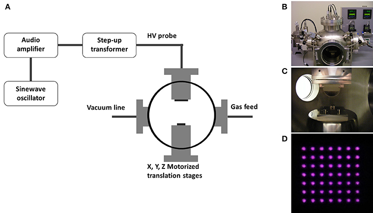
Figure 1. (A) Schematic diagram of the microplasma reactor showing the X–Y–Z translation sample stage, top flange for mounting the microplasma source, helium gas feed and vacuum line ports and the power supply system. Photographs are shown of the (B) microplasma reactor, (C) sample stage and microplasma source, and (D) the microplasma array ignited in helium.
Time-of-Flight Secondary ion Mass Spectrometry (ToF-SIMS)
ToF-SIMS analyses were performed using a PHI TRIFT V nanoToF (Physical Electronics Inc.) equipped with a pulsed liquid metal 79Au+ primary ion gun (LMIG), operating at 30 kV. The extractor current of the ion source was maintained at 3 μA. Surface analyses were performed using “bunched” Au1 beam settings.
Mosaic images were acquired over 3 × 3 mm2 area with a 300 μm raster size. Four mass spectra were collected in negative SIMS mode from region of interest (RoI) at the center of randomly selected treated spots within the array. Mass calibration of the spectra was undertaken using CH−, C2H−, and Cl− ions. Experiments were performed in “static mode” at a pressure ≤ 3.8 × 10⁻⁸ Torr to mitigate the effects of sample damage.
Measurement of RONS in Solution
The dye 2,7-dichlorodihydrofluorescein (DCFH) diacetate (DCFH-DA, Sigma) was used to measure the presence of RONS in solution. The dye is sensitive to a range of RONS including H2O2, OH• and ROO• [51] and NO• and ONOO− [52], and its relative reactivity with RONS has been measured [53]. A stock solution was prepared by dissolving the DCFH-DA powder in ethanol to a concentration of 2 mM. The stock was stored at −20°C until use. DCFH-DA was deacetylated by adding 500 μl of the stock to 2 ml of 10 mM NaOH and incubating for 30 min at 25°C in the dark. The deacetylated DCFH solution was then neutralized by adding 10 ml of phosphate buffered saline (PBS, pH 7.4). The solution was stored in the dark at 4°C until use and discarded if not used within 1 day. Within 1 min after the microplasma array treatment, 100 μl of DCFH was incubated over the area of the PS surface that was exposed to the microplasma array. The solution was incubated in the dark at −25°C for 30 min in a custom-built humidified chamber to prevent evaporation. Afterwards, the solution was transferred to a 96-well multi-well plate and the fluorescence was recorded on a microplate reader (Labtech Fluostar Omega, BMG) at λexcitation = 485 nm and λemission = 520 nm for the oxidized DCFH product (2,7-dichlorofluorescein, DCF). The control was DCFH incubated over the untreated PS under the same conditions as described above. The normalized fluorescence was calculated according to the following equation:
Normalized fluorescence = (fluorescence of test solution/fluorescence control solution) – 1
Results and Discussion
Characterization of the Optical Emission
An example of the spectrally integrated optical emission from the microplasma array is shown in Figure 2 for a pressure of 760 Torr, applied-voltage frequency of 10 kHz (period 100 μs) and applied voltages over the range 600–800 Vpk−pk. The discharge is observed to ignite in every cavity and the intensity is distributed relatively evenly over the whole array as shown in Figure 2A. The intensity of the optical emission is observed to be slightly larger toward the top of the array, and this could be due to the relative proximity of the powered electrode. However, the spatial uniformity of the emission is dependent upon the applied voltage, as shown in Figure 2B, where the spatial uniformity is higher for smaller amplitudes of the applied voltage.
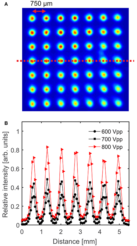
Figure 2. (A) Image of the microplasma array for an applied voltage of 800 Vpk−pk, pressure of 760 Torr and an applied-voltage frequency of 10 kHz, where the relative intensity is shown by the colors, and (B) relative intensity of the optical emission for 600–800 Vpk−pk, as measured along the line-of-sight shown by the dashed line in (A). The solid lines are included as a visual guide.
The spatially averaged and spectrally integrated intensity of the optical emission was measured for varying driving-voltage amplitude and frequency, and with respect to the ambient pressure. From the nominal conditions of 800 Vpk−pk, 10 kHz (period 100 μs) and 760 Torr, the optical emission intensity is shown in Figure 3 for varying Figure 3A applied voltage, Figure 3B applied-voltage frequency and Figure 3C pressure. Figure 3 shows that elevated optical emission is detected for increasing applied voltage, increasing applied-voltage frequency and decreasing pressure. As shown in Figure 3A, although the increase in array-averaged optical emission shows an approximately linear dependence with applied voltage, there is a relatively step increase in the intensity over the range 750–800 Vpk−pk, as is consistent with the spatial distributions shown in Figure 2B. As shown in Figure 3B, the spatially averaged optical emission is observed to increase with respect to the frequency of the applied voltage. However, an investigation of the influence of the applied-voltage frequency on the number of discharge pulses per voltage half-cycle, the frequency-averaged optical emission, and the power dissipated in each microplasma cavity remains the subject of future work. In contrast to the applied voltage and applied-voltage frequency, increases in the operating pressure are correlated with decreases in the intensity of spatially averaged optical emission as shown in Figure 3C. This is consistent with an increased discharge confinement, previously observed for increasing pressure in inverted square pyramid silicon microplasma arrays [34].
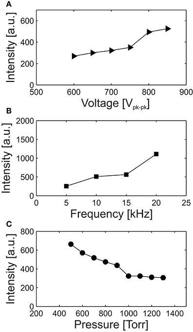
Figure 3. Variation in the intensity of the optical-emission, spatially averaged over the microplasma array, with respect to the (A) applied voltage, (B) applied-voltage frequency, and (C) pressure. For all cases, the conditions apart from the varied parameter are 800 Vpk−pk, 10 kHz, and 760 Torr. The solid lines are included as a visual guide.
To investigate the time-resolved optical emission, images with an acquisition time of 1 μs were acquired at regular intervals throughout the voltage period as shown in Figure 4 for an applied-voltage frequency of 10 kHz. To obtain the image sequence, the ICCD was gated with respect to the applied voltage and one image was obtained per voltage cycle, i.e., the image series was obtained over several voltage cycles.
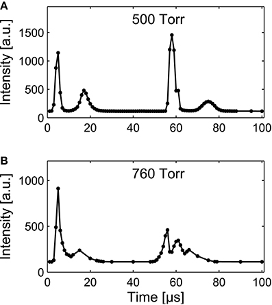
Figure 4. Variation of the optical emission intensity, spatially averaged over the microplasma array, with respect to time within the applied-voltage cycle at 10 kHz (period 100 μs), 800 Vpk−pk, and pressures of (A) 500 Torr and (B) 760 Torr. The solid lines are included as a visual guide.
For pressures of 500 and 760 Torr, shown in Figures 4A,B, respectively, the discharge is observed to ignite in two bursts per voltage cycle with one burst of discharge activity per half-cycle. As described in previous imaging studies of microplasma arrays [54, 55], within each half-cycle of the applied voltage (50 μs duration) the plasma activates in a series of pulses, the first of which exhibits the largest optical-emission intensity and occurs when the electric field between the electrodes becomes sufficiently large to generate an electron avalanche and Townsend discharge. For both pressure cases, following the first activation in each half-cycle the plasma extinguishes when the accumulation of surface charge on the dielectric causes a sufficient reduction of the electric field. However, as the amplitude of the applied voltage continues to increase, it is possible for a subsequent discharge to form during the same half-cycle. Here, the required increase in the strength of the electric field can depend upon the presence of helium metastables that are present following the previous activation [55]. Similar behavior has previously been observed in kilohertz-driven atmospheric-pressure barrier discharges [56, 57].
ToF-SIMS Analysis of Microplasma Patterned Polystyrene
Pressure-Dependent Microplasma Array Treatment
To investigate the hypothesis that changing the microplasma array operating parameters produces measurable changes in the subsequent microscale surface modification, a PS polymer was chosen as a model biomaterial. PS is an ideal material for this study because it is widely utilized in cell culture where it is commonly referred to as tissue culture PS (TCPS). The surface of TCPS is usually treated by a low-pressure plasma that chemically modifies (oxidizes) the surface and improves its characteristics for protein adsorption and cell attachment.
We first analyzed the intensity of the various fragments created in the PS surface following microplasma array treatment. Figure 5 presents negative-ion mass spectra over the mass range 0–100 (m/z) acquired from the RoI of a microplasma-patterned PS at an operating pressure of 500 Torr and from the control sample, i.e., untreated PS. Comparing the mass spectra of the two surfaces, we found that the mass spectra of the untreated PS have high intensity hydrocarbon peaks that are consistent with the chemical structure of PS. However, after plasma treatment a substantial increase in the intensity of peaks assigned to (O−) and (OH−) fragments were observed, together with the emergence of oxygen-, nitrogen- and oxygen/nitrogen-containing fragments. In addition, we observed the presence of oxygen and nitrogen moieties on the surface, which may be the precursors of RONS. All these different fragments are highlighted in the negative-ion survey mass spectra of Figure 5. As seen in Figure 5B, and were also detected on PS after microplasma array treatment. Currently, we do not know the source of sulfur. Although great care was taken handling the samples, the experiments were not performed under cleanroom conditions. Therefore, it is possible that sulfur-containing molecules in the ambient environment also reacted with the highly-reactive surface during transfer of the samples from the microplasma reactor to the ToF-SIMS instrument. We also examined the high-resolution spectra of representative negative-ion fragments, as shown in Figures 6A–E. Figure 6A shows the presence of small intensity peaks representing O− and OH− fragments in the surface of untreated PS, which indicates minor surface oxidation (perhaps due to manufacturing and aging processes). The intensity of these fragments increased substantially after plasma treatment. Analysis of the region between 23.5 and 26.5 m/z (Figure 6B) in the mass spectra revealed a decline in the intensity of hydrocarbon fragments—, C2H−, and C2 and the emergence of a new peak assigned to CN− at m/z 26.00. High-resolution spectra presented in Figures 6C–E show the appearance of new peaks assigned to CNO−(m/z 41.997), (m/z 44.997), and (m/z 45.991), respectively, on the PS surface that was treated with the microplasma array.
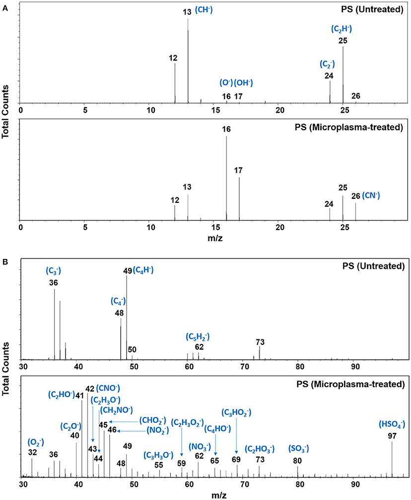
Figure 5. Negative-ion ToF-SIMS mass spectra of untreated and microplasma array treated polystyrene, over the mass range 0–30 m/z (A) and 30–100 m/z (B). Microplasma array treatment was performed at 500 Torr.
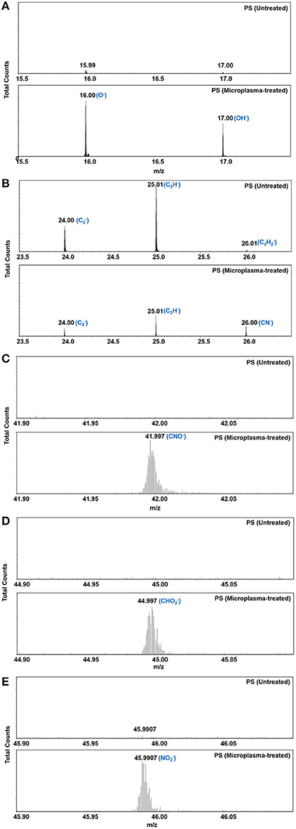
Figure 6. High-resolution negative-ion ToF-SMS mass spectra (A–E) for representative negative-ion fragments on polystyrene before and after microplasma array treatment. Microplasma array treatment was performed at 500 Torr.
We also examined how the operating pressure of the microplasma array affects the size, fidelity and surface chemistry of the microspots (all other parameters were kept constant). For this purpose, mosaic negative-ion ToF-SIMS images (3 × 3 mm2) were acquired on the microplasma array patterned PS substrates at operating pressures of 500, 760, and 1000 Torr. Figure 7 shows the normalized images of the negative-ion fragments (O−) and (C2H−). High-fidelity in the microspot size was achieved within each microarray with smaller spot sizes obtained at 1000 Torr compared to 500 and 760 Torr. A relatively high number of counts for O−, indicating a high level of oxygen, was achieved within the regions exposed to the microdischarges as a result of post-treatment oxidation. The introduction of oxygen to the surface of regions exposed to the individual microplasma discharges, led to a reduction in the intensity of hydrocarbon fragments, as demonstrated by the decline in the intensity of the negative-ion fragment (C2H−) within the treated spots compared to the background area. Although the chemistry was generally homogeneous within the treatment area, the oxygen distribution on some of the samples formed a (slight) ring-shaped pattern; e.g., see the images for O− for the sample treated at 760 Torr in Figure 7. A helium microplasma jet was also shown to deliver RONS onto surfaces in a ring-shaped pattern. The ring-shaped distribution of RONS is thought to arise from the generation of ground state atomic oxygen within the tube of a helium plasma jet [58]. The helium gas flow is thought to displace the atomic oxygen in the tube, effectively “pushing” the atomic oxygen to the walls of the tube [59]. Although the microplasma array treatment was performed under static flow conditions, it is possible that ion momentum transfer to the neutral helium gas created local convection currents that “pushed” the reactive species outwards from the center of the microplasma discharge [59, 60], leading to the ring-shaped distribution of RONS generated on some of the samples. Further detailed analysis will be required to test this conjecture.
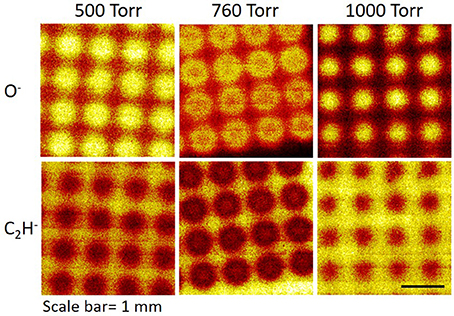
Figure 7. Mosaic negative-ion ToF-SIMS images (3 × 3 mm2) on microplasma-patterned polystyrene substrates for microplasma array treatments undertaken at 500, 760, and 1000 Torr. The brighter regions indicate higher counts for the selected fragment.
To assess how the operating pressure affects the surface chemistry of the microspots, RoI negative mass spectra were acquired from a random selection of four spots within the array of each microplasma array-treated sample and the normalized intensities of the selected fragments (O−) and (C2H−) were plotted in Figure 8 for comparison. The normalized intensity of O− was observed to reduce slightly when the operating pressure was increased from 500 to 760 Torr. However, the reduction was more significant when the operating pressure increased to 1000 Torr. The opposite trend was observed for the hydrocarbon fragment C2H−. We expect that at the lowest operating pressure (500 Torr), the microplasma discharges extend further out of the cavities, and this could result in a higher flux of reactive species reaching the PS surface. However, when the operating pressure increases to 760 and 1000 Torr, the microplasmas become more confined (a reduction in discharge size) within the cavities, resulting in a lower level of treatment. We based our interpretation on the findings by Ostrom and Eden [34], who investigated the dependence of plume contour with respect to the operating pressure of the array. In the present work, we determined that the surface analysis results are consistent with the optical emission as shown in Figure 3.
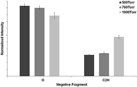
Figure 8. Normalized intensities of the ToF-SIMS negative-ion fragments (O−) and (C2H−) from the microplasma-patterned polystyrene samples at 500, 760, and 1000 Torr.
Detection of Reactive Oxygen and Nitrogen Species (RONS)
Here, we have probed for moieties in the surface of modified PS that may be the precursors of RONS (described in Section: Detection of RONS in Solution). It is difficult to analyse the chemistry on the microplasma array treated PS surfaces, given the microscopic treatment dimensions of the chemical features. X-ray photoelectron spectroscopy could not be used to analyse the surface chemistry because the technique was not sensitive enough to detect the relatively small concentrations of chemical functional groups (especially N- and O-containing functional groups) generated by the microplasma array treatment. This is exacerbated by a smaller aperture needed for small-spot RoI analysis that further reduces the signal leading to a low signal-to-noise ratio. Longer spectral collection times can improve this; however, this also leads to potential damage to the surface. Therefore, ToF-SIMS was used to probe for the possible RONS precursors based upon a knowledge of RONS that are commonly generated by atmospheric-pressure plasmas [61]. The RONS investigated were: O− (oxygen, m/z 15.996), OH− (hydroxyl, m/z 17.004), NO− (nitric oxide, m/z 30.001), (superoxide, m/z 31.991), O2H− (peroxide, m/z 32.997), (nitrite, m/z 45.997), (nitrate, m/z 61.988), and ONOO− (peroxynitrite, m/z 61.998). The selected RONS are important in the emerging field of “plasma medicine” due to their potential therapeutic benefits [62]. Figure 9 presents the normalized intensity of a range of RONS compared to the untreated PS (control). The control sample shows a low level of surface oxidation with O− and OH− as the main fragments. After microplasma array treatment, the PS surface became enriched with RONS, and their surface intensities vary in the following order: O− > OH− > > > > O2H− > NO−. It is interesting to observe that the intensities of these fragments change as a function of pressure. For example, the intensity of O− and decreased when the operating pressure was increased from 500 to 1000 Torr. However, the intensities of and showed the opposite trend, i.e., increasing over the same pressure range. The intensity of NO− and O2H− fragments remained unchanged with respect to varying pressure; however, the peak intensities of these RONS were much lower compared to the other RONS, indicating that they were not efficiently generated on the PS during microplasma array treatment. There are two possible explanations for the decrease in O− and compared to the increase in and with increasing pressure. At lower pressures, the spatially averaged optical emission from the discharge is more intense as shown in Figure 3C, which is consistent with a larger degree of surface modification as shown in Figure 7. Under these conditions, the microplasma discharge can also induce more bond-breaking on the PS leading to the generation of lower molecular weight fragments such as O− and as shown in Figure 8. Conversely, at higher pressures the collision frequency increases and this favors the formation of higher molecular weight molecules such as and . The surface area for which treatment occurs decreases with increasing pressure, and this appears to correlate with the decrease in spatially averaged optical emission intensity observed in Figure 3C. If the peak optical emission intensity remains constant and the coverage increases, it could indicate that the discharge power is increasing and this would be consistent with an increase in the intensity of the spatially averaged optical emission, degree of dissociation and production of RONS. Overall, these results suggest that the generation of RONS on the PS surface can potentially be controlled by varying the pressure during microplasma array treatment.
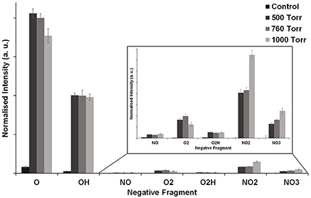
Figure 9. Normalized intensities from negative-ion ToF-SIMS mass spectra of RONS detected on microplasma-patterned polystyrene surfaces at 500, 760, and 1000 Torr. Investigated RONS moieties include O−, OH−, NO−, , O2H−, , and . The control sample was untreated polystyrene.
Detection of RONS in Solution
In addition to ToF-SIMS, a fluorescence based assay using the chemical reporter DCFH was used to detect RONS on PS surfaces after microplasma array treatment using the procedure established in reference [59]. RONS were generated on the PS surface during and/or after completion of the microplasma array treatment following subsequent exposure to the ambient air. RONS were readily detected on the surface after treatment as shown in Figure 10. In general, the reactivity of the PS surface following exposure to the microplasma array was higher for lower pressures (500 and 760 Torr) compared to the higher pressure case of 1000 Torr. This result is consistent with the increased intensity of the optical emission (Figure 3C) and increased degree of surface modification (Figure 8) that was observed for the lower-pressure cases.
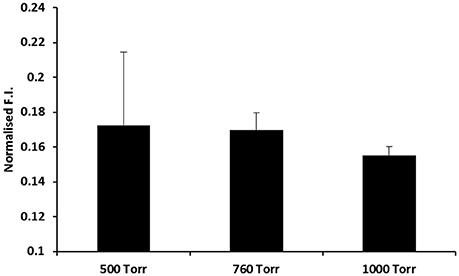
Figure 10. Detection of RONS on polystyrene after microplasma array treatment using a chemical reporter method. The polystyrene surfaces were probed with the broad range DCFH RONS reporter after microplasma array treatment for 60 s at 500, 760, and 1000 Torr. Normalized fluorescence intensity (F.I.) is shown on the y-axis.
The detection of potential RONS precursors on the treated PS surface could be useful as it provides information on the type of RONS that can be generated by microplasma arrays. This information is also useful if microplasma arrays are used in the treatment of solutions or biological material. For examples, microplasma arrays are currently being evaluated in the sterilization of surfaces [63, 64], the decontamination of water [65] and in the stimulation of wound healing through the plasma-induced modification of biomolecules [39, 66].
Future Directions in the Use of Microplasma Arrays to Functionalize Surfaces with RONS
RONS are important signaling molecules in the regulation of cellular and physiological processes and are vital to life [67]. Atmospheric-pressure plasmas interacting with air and/or water vapor provide a rich source of RONS [62], and could play an important role in oxidation-reduction biology and medicine as previously reviewed [47]. It has been experimentally shown how RONS might intervene in cellular signaling processes to target the destruction of bacteria and or cancerous cells [68–72]. It is now widely accepted that atmospheric-pressure plasmas can be used to deliver RONS into solution or onto a soft medium (e.g., on an agar plate or on living tissue) to regulate cellular functions.
Apart from using atmospheric-pressure plasmas to deliver RONS into solutions or onto surfaces, it may also be advantageous to generate a reservoir of RONS in surfaces for subsequent biological reactions in solution. Achieving this on the microscale level through microplasma array technologies could support the development of substrate platforms for biosensing or biomaterial applications. For example, the development of arrays of RONS such as nitric oxide or hydrogen peroxide could be used in the development of biomaterials that target signaling mechanisms in bacteria to prevent biofilm formation. Both nitric oxide and hydrogen peroxide are thought to be important signaling molecules in the dispersion of biofilms [73, 74]. In this paper, we have demonstrated that it is possible to functionalize a substrate with RONS and that the RONS can be subsequently participate in a molecular specific reaction in solution. Future research in this area might enable the development of microplasma technologies for the patterning of substrate surfaces with reservoirs of specific types of RONS for use in biology and medicine.
Conclusions
Using a microplasma array, a straightforward and versatile approach was presented for micro-patterning reactive chemical features onto temperature-sensitive material surfaces. The time-averaged and time-resolved optical emission from the microplasma array was characterized with respect to the applied voltage, applied-voltage frequency, and the operating pressure. The intensity of the optical emission from individual discharge cavities within the microplasma array increased as the applied voltage and frequency were increased, but decreased for increasing pressure. The utility of the microplasma array was demonstrated in the localized microscale surface treatment of a polystyrene substrate. The surfaces were characterized by ToF-SIMS imaging combined with small-spot RoI analysis. The concentration of oxygen incorporated into the surface was observed to be influenced by the pressure, and these results are consistent with measurements of the optical emission. Apart from oxygen, the microplasma array treatment was shown to generate a highly reactive surface consisting of RONS, which can potentially be used in the development of new biomaterial surfaces. It is reasonable to suggest that these RONS could come from the moieties observed in SIMS; however, work is ongoing to better understand the underlying mechanisms.
We anticipate that precise spatial control over reactive chemical surface modifications will enable the chemistry of surfaces to be tailored for a range of applications, including high-throughput screening and cell-biomolecule-biomaterial interactions.
Author Contributions
ES, JD, JO, and SA designed and performed experiments, and wrote the paper. JB, RB, CC, and RS designed experiments and wrote the paper.
Conflict of Interest Statement
The authors declare that the research was conducted in the absence of any commercial or financial relationships that could be construed as a potential conflict of interest.
References
1. Schoenbach KH, Becker K. 20 years of microplasma research: a status report. Eur Phys J D (2016) 70:29. doi: 10.1140/epjd/e2015-60618-1
2. Eden JG, Park SJ, Cho JH, Kim MH, Houlahan TJ, Li B, et al. Plasma science and technology in the limit of the small: microcavity plasmas and emerging applications. IEEE Trans Plasma Sci. (2013) 41:661–75. doi: 10.1109/TPS.2013.2253132
3. Eun CK, Gianchandani YB. Microdischarge-based sensors and actuators for portable microsystems: selected examples. IEEE J Quantum Electron. (2012) 48:814–26. doi: 10.1109/JQE.2012.2189199
4. Schoenbach KH, Zhu W. High-pressure microdischarges: sources of ultraviolet radiation. IEEE J Quantum Electron. (2012) 48:768-82. doi: 10.1109/JQE.2012.2185686
5. Becker KH, Schoenbach KH, Eden JG. Microplasmas and applications. J Phys D Appl Phys. (2006) 39:R55. doi: 10.1088/0022-3727/39/3/R01
6. Eden JG, Park SJ, Kim KS. Arrays of nonequilibrium plasmas confined to microcavities: an emerging frontier in plasma science and its applications. Plasma Sources Sci Technol. (2006) 15:S67. doi: 10.1088/0963-0252/15/2/S09
7. Foest R, Schmidt M, Becker K. Microplasmas, an emerging field of low-temperature plasma science and technology. Int J Mass Spectrom. (2006) 248:87–102. doi: 10.1016/j.ijms.2005.11.010
8. Iza F, Kim GJ, Lee SM, Lee JK, Walsh JL, Zhang YT, et al. Microplasmas: sources, particle kinetics, and biomedical applications. Plasma Process Polym. (2008) 5:322–44. doi: 10.1002/ppap.200700162
9. Al-Bataineh SA, Szili EJ, Gruner PJ, Priest C, Griesser HJ, Voelcker NH, et al. Fabrication and operation of a microcavity plasma array device for microscale surface modification. Plasma Process Polym. (2012) 9:638–46. doi: 10.1002/ppap.201100166
10. Szili EJ, Al-Bataineh SA, Bryant PM, Short RD, Bradley JW, Steele DA. Controlling the spatial distribution of polymer surface treatment using atmospheric-pressure microplasma jets. Plasma Process Polym. (2011) 8:38–50. doi: 10.1002/ppap.201000082
11. Szili EJ, Al-Bataineh SA, Ruschitzka P, Desmet G, Priest C, Griesser HJ, et al. Microplasma arrays: a new approach for maskless and localized patterning of materials surfaces. RSC Adv. (2012) 2:12007–10. doi: 10.1039/c2ra21504g
12. Szili E, Thissen H, Hayes JP, Voelcker N. A biochip platform for cell transfection assays. Biosens Bioelectron. (2004) 19:1395-400. doi: 10.1016/j.bios.2003.12.019
13. Goessl A, Golledge S, Hoffman AS. Plasma lithography—thin-film patterning of polymers by RF plasma polymerization II: study of differential binding using adsorption probes. J Biomater Sci Polymer Edn. (2001) 12:739–53. doi: 10.1163/156856201750411639
14. Menzies DJ, Cowie B, Fong C, Forsythe JS, Gengenbach TR, McLean KM, et al. One-step method for generating PEG-like plasma polymer gradients: chemical characterization and analysis of protein interactions. Langmuir (2010) 26:13987–94. doi: 10.1021/la102033d
15. Dai L, Griesser HJ, Mau AWH. Surface modification by plasma etching and plasma patterning. J Phys Chem B (1997) 101:9548–54. doi: 10.1021/jp970562d
16. Chen HY, Lahann J. Vapor-assisted micropatterning in replica structures: a solventless approach towards topologically and chemically designable surfaces. Adv Mater. (2007) 19:3801–8. doi: 10.1002/adma.200602830
17. Barbulovic-Nad I, Lucente M, Yu S, Mingjun Z, Wheeler AR, Bussmann M. Bio-microarray fabrication techniques - a review. Crit Rev Biotechnol. (2006) 26:237–59. doi: 10.1080/07388550600978358
18. Hook AL, Voelcker NH, Thissen H. Patterned and switchable surfaces for biomolecular manipulation. Acta Biomater. (2009) 5:2350–70. doi: 10.1016/j.actbio.2009.03.040
19. Klages C-P, Hinze A, Lachmann K, Berger C, Borris J, Eichler M, et al. Surface technology with cold microplasmas. Plasma Process Polym. (2007) 4:208–18. doi: 10.1002/ppap.200600116
20. Uwe S, Antje D, Paul H, Michael T, Klaus K, Claus-Peter K, et al. Multilayer photoresist stamps for selective plasma treatment in micrometer scales. Plasma Process Polym. (2009) 6:228–33. doi: 10.1002/ppap.200800217
21. Penache C, Gessner C, Betker T, Bartels V, Hollaender A, Klages CP. Plasma printing: patterned surface functionalisation and coating at atmospheric pressure. IEE Proc Nanobiotechnol. (2004) 151:139. doi: 10.1049/ip-nbt:20040836
22. Uwe S, Antje D, Paul H, Andreas G, Michael T, Claus-Peter K, et al. Porous photoresist stamps for selective plasma treatment. Plasma Process Polym. (2010) 7:9–15. doi: 10.1002/ppap.200900063
23. Möbius A, Elbick D, Weidlich E-R, Feldmann K, Schüßler F, Borris J, et al. Plasma-printing and galvanic metallization hand in hand - a new technology for the cost-efficient manufacture of flexible printed circuits. Electrochim Acta (2009) 54:2473–7. doi: 10.1016/j.electacta.2008.08.050
24. Hinze A, Klages C-P, Zänker A, Thomas M, Wirth T, Unger WES. ToF-SIMS Imaging of DBD-Plasma-Printed Microspots on BOPP Substrates. Plasma Process Polym. (2008) 5:460–70. doi: 10.1002/ppap.200700138
25. Klages C-P, Berger C, Eichler M, Thomas M. Microplasma-based treatment of inner surfaces in microfluidic devices. Contrib Plasma Phys. (2007) 47:49–56. doi: 10.1002/ctpp.200710008
26. Bryant PM, Szili EJ, Whittle T, Park S-J, Eden JG, Al-Bataineh S, et al. The use of a micro-cavity discharge array at atmospheric pressure to investigate the spatial modification of polymer surfaces. Surf. Coat. Technol. (2010) 204:2279–88. doi: 10.1016/j.surfcoat.2009.12.020
27. Al-Bataineh SA, Szili EJ, Mishra A, Park S-J, Eden JG, Griesser HJ, et al. Design of a microplasma device for spatially localised plasma polymerisation. Plasma Process Polym. (2011) 8:695–700. doi: 10.1002/ppap.201000176
28. Puchberger-Enengl D, Krutzler C, Keplinger F, Vellekoop MJ. Single-step design of hydrogel-based microfluidic assays for rapid diagnostics. Lab Chip. (2014) 14:378–83. doi: 10.1039/C3LC50944C
29. Priest C, Gruner PJ, Szili EJ, Al-Bataineh SA, Bradley JW, Ralston J, et al. Microplasma patterning of bonded microchannels using high-precision “injected” electrodes. Lab Chip (2010) 11:541–4. doi: 10.1039/C0LC00339E
30. Gallegos D, Long KD, Yu H, Clark PP, Lin Y, George S, et al. Label-free biodetection using a smartphone. Lab Chip (2013) 13:2124–32. doi: 10.1039/c3lc40991k
31. Muir BW, Fairbrother A, Gengenbach TR, Rovere F, Abdo MA, McLean KM, et al. Scanning probe nanolithography and protein patterning of low-fouling plasma polymer multilayer films. Adv Mater. (2006) 18:3079–82. doi: 10.1002/adma.200600343
32. Shah SS, Howland MC, Chen L, Silangcruz J, Verkhoturov SV, Schweikert EA, et al. Micropatterning of proteins and mammalian cells on indium tin oxide. ACS Appl Mater Interfaces (2009) 1:2592–601. doi: 10.1021/am900508m
33. Kushner MJ. Modeling of microdischarge devices: pyramidal structures. J Appl Phys. (2004) 95:846. doi: 10.1063/1.1636251
34. Ostrom NP, Eden JG. Visible emission contours for neon plasmas in silicon microcavity discharge devices: pressure dependence of spatially resolved fluorescence above the anode plane. IEEE Trans Plasma Sci. (2005) 33:576–7. doi: 10.1109/TPS.2005.845289
35. France RM, Short RD. Effects of energy transfer from an argon plasma on the surface chemistry of poly(styrene), low density poly(ethylene), poly(propylene) and poly(ethylene terephthalate). J Chem Soc Faraday Trans. (1997) 93:3173–8. doi: 10.1039/a702311a
36. Gomathi N, Sureshkumar A, Neogi S. RF plasma-treated polymers for biomedical applications. Curr Sci. (2008) 94:1478. Available online at: http://www.currentscience.ac.in/Downloads/article_id_094_11_1478_1486_0.pdf
37. Park YW, Inagaki N. A new approach for selective surface modification of fluoropolymers by remote plasmas. J Appl Polym Sci. (2004) 93:1012–20. doi: 10.1002/app.20553
38. Stoffels E, Gonzalvo YA, Whitmore TD, Seymour DL, Rees JA. Mass spectrometric detection of short-living radicals produced by a plasma needle. Plasma Sources Sci Technol. (2007) 16:549. doi: 10.1088/0963-0252/16/3/014
39. Desmet G, Michelmore A, Szili EJ, Park S-J, Eden JG, Short RD, et al. On the effects of atmospheric-pressure microplasma array treatment on polymer and biological materials. RSC Adv. (2013) 3:13437–45. doi: 10.1039/c3ra42025f
40. Attri P, Kumar N, Park JH, Yadav DK, Choi S, Uhm HS, et al. Influence of reactive species on the modification of biomolecules generated from the soft plasma. Sci Rep. (2015) 5:8221. doi: 10.1038/srep08221
41. Antoniu A, Nakajima T, Kurita H, Mizuno A. Safety evaluation of nonthermal atmospheric pressure plasma liquid treatment: single DNA molecule-based method. J Electrostat. (2014) 72:210–7. doi: 10.1016/j.elstat.2014.02.004
42. Kurita H, Miyachika S, Yasuda H, Takashima K, Mizuno A. Use of molecular beacons for the rapid analysis of DNA damage induced by exposure to an atmospheric pressure plasma jet. Appl Phys Lett. (2015) 107:263702. doi: 10.1063/1.4939044
43. Tanaka Y, Yasuda H, Kurita H, Takashima K, Mizuno A. Analysis of the inactivation mechanism of bacteriophage ΦX174 by atmospheric pressure discharge plasma. IEEE Trans Ind Appl. (2014) 50:1397–401. doi: 10.1109/TIA.2013.2274260
44. Yasuda H, Hashimoto M, Rahman MM, Takashima K, Mizuno A. States of biological components in bacteria and bacteriophages during inactivation by atmospheric dielectric barrier discharges. Plasma Process Polym. (2008) 5:615–21. doi: 10.1002/ppap.200800036
45. Yasuda H, Miura T, Kurita H, Takashima K, Mizuno A. Biological evaluation of DNA damage in bacteriophages inactivated by atmospheric pressure cold plasma. Plasma Process Polym. (2010) 7:301–08. doi: 10.1002/ppap.200900088
46. Takai E, Kitamura T, Kuwabara J, Ikawa S, Yoshizawa S, Shiraki K, et al. Chemical modification of amino acids by atmospheric-pressure cold plasma in aqueous solution. J Phys D Appl Phys. (2014) 47:285403. doi: 10.1088/0022-3727/47/28/285403
47. Graves DB. The emerging role of reactive oxygen and nitrogen species in redox biology and some implications for plasma applications to medicine and biology. J Phys D Appl Phys. (2012) 45:263001. doi: 10.1088/0022-3727/45/26/263001
48. Ideno T, Ichiki T. Hydrophilic patterning of polymer surfaces using a scanning microplasma jet source. J Photopolym Sci Technol. (2004) 17:173–6. doi: 10.2494/photopolymer.17.173
49. West J, Michels A, Kittel S, Jacob P, Franzke J. Microplasma writing for surface-directed millifluidics. Lab Chip (2007) 7:981–83. doi: 10.1039/b706788g
50. Olabanji OT, Bradley JW. Side-on surface modification of polystyrene with an atmospheric pressure microplasma jet. Plasma Process Polym. (2012) 9:929–36. doi: 10.1002/ppap.201200011
51. Gomes A, Fernandes E, Lima JLFC. Fluorescence probes used for detection of reactive oxygen species. J Biochem Biophys Methods (2005) 65:45–80. doi: 10.1016/j.jbbm.2005.10.003
52. Gomes A, Fernandes E, Lima JFC. Use of fluorescence probes for detection of reactive nitrogen species: a review. J Fluoresc. (2006) 16:119–39. doi: 10.1007/s10895-005-0030-3
53. Setsukinai K-I, Urano Y, Kakinuma K, Majima HJ, Nagano T. Development of novel fluorescence probes that can reliably detect reactive oxygen species and distinguish specific species. J Biol Chem. (2003) 278:3170–5. doi: 10.1074/jbc.M209264200
54. Boettner H, Waskoenig J, O'Connell D, Kim TL, Tchertchian PA, Winter J, et al. Excitation dynamics of micro-structured atmospheric pressure plasma arrays. J Phys D Appl Phys. (2010) 43:124010. doi: 10.1088/0022-3727/43/12/124010
55. Waskoenig J, O'Connell D, von der Gathen VS, Winter J, Park SJ, Eden JG. Spatial dynamics of the light emission from a microplasma array. Appl Phys Lett. (2008) 92:101503. doi: 10.1063/1.2894227
56. Golubovskii YB, Maiorov VA, Behnke J, Behnke JF. Modelling of the homogeneous barrier discharge in helium at atmospheric pressure. J Phys D Appl Phys. (2003) 36:39. doi: 10.1088/0022-3727/36/1/306
57. Radu I, Bartnikas R, Czeremuszkin G, Wertheimer MR. Diagnostics of dielectric barrier discharges in noble gases: atmospheric pressure glow and pseudoglow discharges and spatio-temporal patterns. IEEE Trans Plasma Sci. (2003) 31:411–21. doi: 10.1109/TPS.2003.811647
58. Sakiyama Y, Knake N, Schröder D, Winter J, Schulz-von der Gathen V, Graves DB. Gas flow dependence of ground state atomic oxygen in plasma needle discharge at atmospheric pressure. Appl Phys Lett. (2010) 97:151501. doi: 10.1063/1.3496041
59. Szili EJ, Bradley JW, Short RD. A “tissue model” to study the plasma delivery of reactive oxygen species. J Phys D Appl Phys. (2014) 47:152002.
60. Marshall SE, Jenkins ATA, Al-Bataineh SA, Short RD, Hong S-H, Thet NT, et al. Studying the cytolytic activity of gas plasma with self-signalling phospholipid vesicles dispersed within a gelatin matrix. J Phys D Appl Phys. (2013) 46:185401. doi: 10.1088/0022-3727/46/18/185401
61. Liu D-X, Rong M-Z, Wang X-H, Iza F, Kong MG, Bruggeman P. Main species and physicochemical processes in cold atmospheric-pressure He + O2 Plasmas. Plasma Process Polym. (2010) 7:846–65. doi: 10.1002/ppap.201000049
62. Kong MG, Kroesen G, Morfill G, Nosenko T, Shimizu T, Dijk JV, et al. Plasma medicine: an introductory review. New J Phys. (2009) 11:115012. doi: 10.1088/1367-2630/11/11/115012
63. Moreau M, Orange N, Feuilloley MGJ. Non-thermal plasma technologies: new tools for bio-decontamination. Biotechnol Adv. (2008) 26:610–7. doi: 10.1016/j.biotechadv.2008.08.001
64. Graves DB. Low temperature plasma biomedicine: a tutorial review. Phys Plasmas (2014) 21:080901. doi: 10.1063/1.4892534
65. Traylor MJ, Pavlovich MJ, Karim S, Hait P, Sakiyama Y, Clark DS, et al. Long-term antibacterial efficacy of air plasma-activated water. J Phys D Appl Phys. (2011) 44:472001. doi: 10.1088/0022-3727/44/47/472001
66. Park CH, Lee JS, Kim JH, Kim D-K, Lee OJ, Ju HW, et al. Wound healing with nonthermal microplasma jets generated in arrays of hourglass microcavity devices. J Phys D Appl Phys. (2014) 47:435402. doi: 10.1088/0022-3727/47/43/435402
67. Halliwell B, Gutteridge JMC. Free Radicals in Biology and Medicine. 4th ed. Oxford: Oxford Univeristy Press (2007).
68. Laroussi M. From killing bacteria to destroying cancer cells: 20 years of plasma medicine. Plasma Process Polym. (2014) 11:1138–41. doi: 10.1002/ppap.201400152
69. Ratovitski EA, Cheng X, Yan D, Sherman JH, Canady J, Trink B, et al. Anti-cancer therapies of 21st century: novel approach to treat human cancers using cold atmospheric plasma. Plasma Process Polym. (2014) 11:1128–37. doi: 10.1002/ppap.201400071
70. Attri P, Kim YH, Park DH, Park JH, Hong YJ, Uhm HS, et al. Generation mechanism of hydroxyl radical species and its lifetime prediction during the plasma-initiated ultraviolet (UV) photolysis. Sci Rep. (2015) 5:9332. doi: 10.1038/srep09332
71. Keidar M. Plasma for cancer treatment. Plasma Sources Sci Technol. (2015) 24:033001. doi: 10.1088/0963-0252/24/3/033001
72. Goree J, Bin L, Drake D, Stoffels E. Killing of S. mutans bacteria using a plasma needle at atmospheric pressure. IEEE Trans Plasma Sci. (2006) 34:1317–24. doi: 10.1109/TPS.2006.878431
73. Jolivet-Gougeon A, Bonnaure-Mallet M. Biofilms as a mechanism of bacterial resistance. Drug Disc Today Technol. (2014) 11:49–56. doi: 10.1016/j.ddtec.2014.02.003
Keywords: microplasma array, reactive oxygen species, reactive nitrogen species, microarray, biomaterials, surface patterning, polystyrene
Citation: Szili EJ, Dedrick J, Oh J-S, Bradley JW, Boswell RW, Charles C, Short RD and Al-Bataineh SA (2017) Microplasma Array Patterning of Reactive Oxygen and Nitrogen Species onto Polystyrene. Front. Phys. 5:1. doi: 10.3389/fphy.2017.00001
Received: 23 November 2016; Accepted: 09 January 2017;
Published: 03 February 2017.
Edited by:
Satoshi Hamaguchi, Osaka University, JapanReviewed by:
Masaaki Nagatsu, Shizuoka University, JapanFumiyoshi Tochikubo, Tokyo Metropolitan University, Japan
Copyright © 2017 Szili, Dedrick, Oh, Bradley, Boswell, Charles, Short and Al-Bataineh. This is an open-access article distributed under the terms of the Creative Commons Attribution License (CC BY). The use, distribution or reproduction in other forums is permitted, provided the original author(s) or licensor are credited and that the original publication in this journal is cited, in accordance with accepted academic practice. No use, distribution or reproduction is permitted which does not comply with these terms.
*Correspondence: Endre J. Szili, endre.szili@unisa.edu.au
Sameer A. Al-Bataineh, sameer.al-bataineh@unisa.edu.au
†Co-first authors.