Quantitative coarse graining of laminar fluid flow penetration in rough boundaries
 Akankshya Majhi
 Lars Kool
 Jasper van der Gucht
 Joshua A. Dijksman
- 1Physical Chemistry and Soft Matter, Wageningen University and Research, Wageningen, Netherlands
- 2Laboratoire de Physique et Mécanique des Milieux Hétérogènes, École Supérieure de Physique et de Chimie Industrielles de la Ville de Paris, Paris, France
- 3Van der Waals-Zeeman Institute, Institute of Physics, University of Amsterdam, Amsterdam, Netherlands
The interaction between a fluid and a wall is described with a certain boundary condition for the fluid velocity at the wall. To understand how fluids behave near a rough wall in a completely laminar flow regime, the fluid velocity at every point on the rough surface may be provided. This approach requires detailed knowledge of, and likely depends strongly on the roughness. Another approach of modelling the boundary conditions of a rough wall is to coarse grain and extract a penetration depth over which on average the fluid penetrates into the roughness. In this work, we examine the impact of well-defined patterned surfaces on the fluid flow behaviour. We considered two extreme cases: one with horizontal ridges and another with vertical ridges on the wall and an intermediate case with ridges at an angle on the wall. We show that for a broad range of periodic roughness patterns and relative flow velocities, a universal penetration depth function can be obtained. We obtain these results with experiments and complementary numerical simulations. We evaluate how this penetration depth depends on the various roughness parameters such as ridge depth, ridge spacing and ridge angle. Our results present a novel approach to investigating wall roughness boundary conditions by considering the penetration depth δ that captures the spatially averaged behaviour of the decaying velocity profile between the asperities. We find that this penetration depth δ can be rescaled into a simple exponential master curve δ = δ∞(1 − e−kD/S) for horizontal ridges with varying depth D and spacing S. A similar variation of δ with D and S is observed for vertical ridges, but with a smaller magnitude δ∞, while for ridges at an angle, the penetration depth lies between the two extreme cases.
1 Introduction
The interaction of a fluid with a wall can be extremely complex, especially when the wall possesses small-scale features [1]. Typically, complexities arise in the form of slip layers [2, 3] and other complicated boundary conditions [4–6]. Slip layers are observed when the fluid, at the fluid-wall interface, flows at a different velocity than the wall itself [6]. These wall-fluid interactions can, however, be tuned to control the fluid flow behaviour further away from the wall. The wall-fluid interactions can be modified in different ways. One approach involves altering the walls of the flow geometry. Such modifications create complex boundary conditions at the wall, which can be introduced either by adding certain geometrical features on the wall [7–11] or by modifying the wetting properties of the wall itself (liquid infused surfaces [12, 13], hydrophobic surfaces [14–17], bubbles [18]). Here, we focus solely on the effects of geometrically altered surfaces.
Geometrical alterations to the walls in the form of well-defined geometrical length scales such as riblets or grooves introduce roughness into the wall. These features can then be systematically varied to understand the influence of roughness on the fluid flow behaviour near the wall. The study on explicitly patterned ribbed surfaces came to prominence around 40 years ago, with inspiration from nature [1, 19–21]. Sharks have denticles on their skin which reduces drag and allows for more efficient swimming. To understand the effect of drag reduction in animals, work has been done on simplified model systems with various designs for ridges such as L-shaped, V-shaped and U-shaped [7, 10, 22]. These studies primarily deal with variations in ridge dimensions such as ridge depth, ridge spacing, ridge width and angle of ridge orientation and in particular, their effect on the performance of the ridged surfaces [10, 22–24]. Since then, several studies have been carried out on engineered patterned ribbed geometries in parallel plate and concentric cylindrical systems. These patterned geometries have been studied in the context of reducing viscous (friction) drag [10, 11, 15, 21, 25–31] or suppressing wall slip [2, 32, 33]. Most of these studies have investigated the viscous drag reduction in the viscous sublayer in turbulent flows. It is to be noted that the viscous drag reduction in turbulent flows is governed by considerably different factors compared to that in laminar flows. Previous studies have examined only the flow within the viscous sublayer in turbulent fluid flow, and considered that the convective terms in the Navier-Stokes equations are negligible compared to the viscous terms, and therefore the flow was studied in the much simpler framework of the Stokes equations [34]. Walsh [26] indicated that microsurface geometry variations change the near-wall structure of the turbulent flow boundary layer, and making them effective in reducing (viscous) drag. Bechert et al. [19, 35] carried out an extensive parametric study on surfaces with longitudinal ribs, where they argued that the velocity profile in between the ridges penetrates to a distance below the ridge tips which they refer to as “protrusion height”. This protrusion height depended on the ridge dimensions and was indicative of the drag reduction. All these studies referred to a single protrusion height for the parallel flow. Later studies by Luchini [34] and Bechert [20, 29, 36] demonstrated the existence of two protrusion heights corresponding to the parallel and cross flow, respectively. Their findings also indicated that the parallel flow protrusion height is always larger than the cross flow one. Despite showing interesting results, their geometries posed a problem in terms of manufacturing and durability. Davies et al. [15] numerically studied the effect of patterned channel walls with alternating microribs and cavities. They investigated the influence of the vapour cavity depth in the entire laminar flow regime and showed significant reduction in the frictional resistance in laminar fluid flow. Their experimental studies were documented in [37]. Djenidi et al. [7, 9] showed that riblets cause a reduction in frictional drag in laminar flows. These drag reducing techniques find applications in the aerospace industry for saving fuel costs [25–28] and also serve as a non-additive drag reduction technology in pipe flow.
Experimental data on the performance of riblets in a laminar flow regime are scarce. Measuring the drag reduction achieved by riblets becomes much more challenging when transitioning from turbulent to laminar boundary layers, primarily due to the relatively lower skin frictions and forces encountered in laminar flow [28]. Several factors contribute to this increased challenge in measuring drag reduction in laminar flow. First, the interaction between the riblets and the wall, which is crucial for drag reduction, mainly occurs in the near-wall region known as the boundary layer. Laminar boundary layers are typically thinner than turbulent boundary layers, which creates difficulties in accurately measuring drag reduction effects near the wall. Second, the reduction in drag in laminar flow is usually smaller, around 10% [28], compared to turbulent flow, because of lower skin frictions and forces. This diminished reduction makes it more challenging to precisely measure such small drag reduction effects in laminar flow. Third, laminar flow features a uniform flow profile, which makes it more difficult to identify subtle changes in the flow behaviour that could indicate drag reduction. Additionally, the classical theory suggests that the roughness does not affect the laminar fluid flow [8, 38]. However, substantial deviations from this theory have been found in subsequent studies [15, 16, 39–42]. For instance, Jung and Bhushan [39] demonstrated that wall roughness reduced the pressure drop up to 30% in a closed channel flow. All these investigations indicate that surface roughness reduces the flow resistance in the laminar flow regime. Such studies still remain an active area of research. For example, recently, McKinley and co-workers [11] used different surface microtextures to study the drag reducing effect on the fluid flow over a range of flow speeds. They examined the interaction of Taylor vortices with the riblets in case of Newtonian fluids. Nickerson and Kornfield [32] have shown that cleated surfaces on parallel plate geometry can be used to suppress wall slip. Although much previous work has established that rough surfaces can be used to prevent wall slip, for instance in rheological measurements, the effect of wall roughness on the laminar flow of the fluid near the wall, specifically, the introduction of secondary flows or the penetration of the fluid flow into the gaps between the ridges on the wall, has not been extensively studied. Additionally, riblets used are complex in structure and the associated flow fields in such geometries are challenging to systematically investigate. Such complexities make the interpretation of stress-based measurements on the effect of rough walls difficult. Therefore, we focus on studying the effect of surface roughness using well-defined riblets in a completely laminar fluid flow regime.
In the present paper, we show that the role of the wall roughness on the boundary layer of a laminar fluid flow can be effectively quantified by a penetration depth for a range of different roughness conditions that sets a decaying velocity profile between the protrusions. The penetration has a similar interpretation as the Navier slip length used in the case of partial wall slip or the protrusion height introduced by Bechert et al. [19, 35]. Our work highlights that a rough surface boundary condition reduces to that of a flat wall at a different geometric location. We confirm this perspective with stress-based measurements. We use simple 3D printed ridged concentric cylinder geometries with ridges of different depth, spacing and orientation. This way of creating rough surfaces gives the ability to systematically investigate the role of a ridge in fluid flow, to demonstrate how the flow penetrates between the ridges and to examine whether there are effects of secondary flows, orthogonal to the primary flow direction. Figure 1A shows examples of patterned geometries. D, S and W are the ridge depth, ridge spacing, and ridge width, respectively. L is the length of the ridged geometry. The ridge angle θ can be varied with respect to the vertical axis. A helical wall patterning for angles between 0° and 90°, will induce secondary flows at all flow rates, leading to the formation of vortices, which are usually only observed at high rotation rates [43].
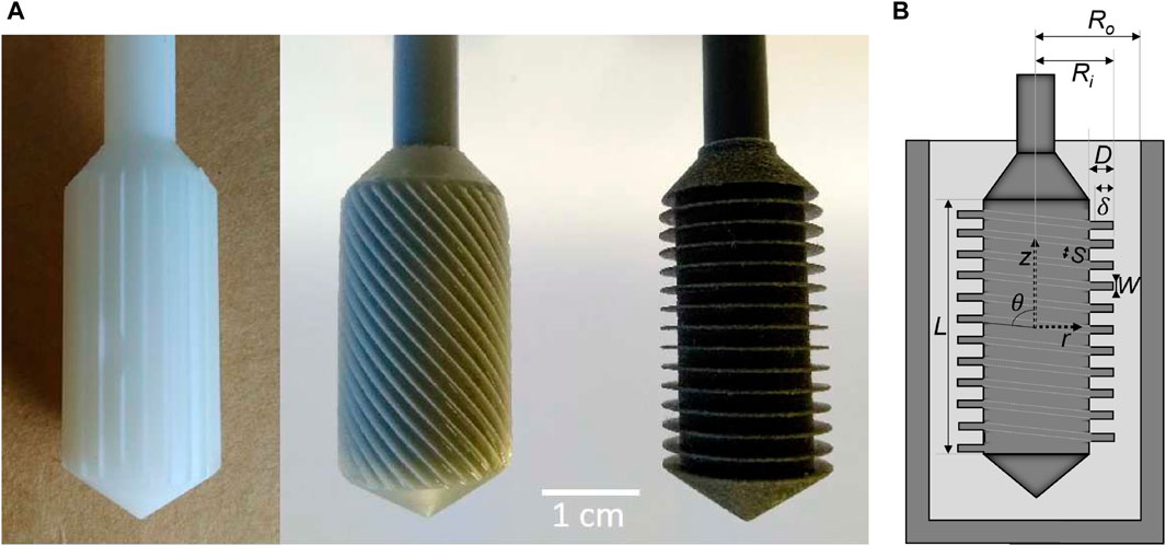
FIGURE 1. (A) 3D printed geometries with patterned surfaces: vertical ridges (left), angled ridges (centre) and horizontal ridges (right). (B) Schematic representation of a concentric cylinder (CC) geometry with angled ridges. Ri and Ro are the radii of the inner and outer cylinder of the ridged geometry, respectively and L is the length of the ridged geometry. Here the inner radius Ri corresponds to the distance from the centre of the coordinate system to the farthest point on the ridges. D is the ridge depth, S is spacing between the ridges, W is the ridge width and δ is the penetration depth.
In this work, we investigate the influence of 3D printed ridged geometries on the flow of a Newtonian fluid at a low Reynolds number using standard concentric cylinder rheology. In Section 2, we first describe the materials, and the experimental and the numerical methods used for the determination of protrusion height. Later in Section 3, we first briefly discuss the numerical results of the flow profile penetration, in order to build the framework for rationalising our experimental findings that are discussed later in this section. We present the simulated flow profiles in different ridged geometries. Subsequently, we explore the flow profile penetration, both experimentally and numerically, for two limiting cases of horizontal and vertical ridges, and then discuss the angled ridge case.
2 Materials and methods
2.1 Design and fabrication of ridged geometries
Custom 3D printed ridged geometries were fabricated on a Stratasys Objet30 Scholar (Stratasys, Ltd.) and a Formlabs 2 SLA (Formlabs, Inc.) printer to fit the Anton Paar rheometer shaft for disposable geometries.
Patterning with 3D printing allows to create well-defined geometries with good control to produce fine features with a dimensional accuracy of ∼100 μm. The benefit of using the 3D printed ridged geometries is that they can be easily incorporated into a flow imaging technique such as MRI [44, 45], which allows to fully quantify the flow profiles and extract the wall stresses present within the system.
The geometries with ridges perpendicular to the rotational axis were designed by making cutouts of various spacings (0.5–3 mm) and depths (0.5–3 mm) from the standard CC17 geometry with constant Ri = 8.5 mm and Ro = 9 mm. They were printed on the Stratasys Objet30 Scholar, using the Vero Black photopolymer (Stratasys, Ltd.) with water-soluble supports. The geometries were printed vertically with a layer thickness of 16 μm.
The geometries with ridges at an angle with respect to the rotational axis were designed with the angle ranging from 10° to 60° with 10° intervals. Geometries with ridge angles between 70° and 90° could not be printed due to limitations of the printing technique. The geometries were designed such that the shortest distance (spacing) between the ridges was 2 mm, with a ridge depth of 1 mm and ridge thickness of 0.3 mm. This was achieved by changing the width and the number of cutouts. The width and the number of cutouts were calculated using a Python script with the length and the diameter of the ridged geometry, ridge angle and shortest distance between the ridges as input. These geometries with angled ridges were fabricated on a Formlabs 2 SLA printer, using the glass reinforced Rigid resin (Formlabs, Inc.) with a layer height of 50 μm and xy-resolution of 140 μm. The support needed for the printing was only attached to the shaft and the top chamber to prevent the introduction of artefacts coming from small residuals of the support material.
The printed geometries were washed twice for 10–15 min in 95% isopropanol. After drying, the geometries were post-cured under a 366 nm lamp for 1.5–2 h. The geometries were rotated 180° halfway through to cure evenly. The support material was removed manually using flush side-clippers after curing. The shaft of all geometries was printed with a diameter of 8 mm and milled down on a lathe to 6.95 mm to fit the Anton Paar shaft for disposable geometries. We determined that this lathe post-processing ensured the best concentricity of the geometry with the Anton Paar rheometer shaft and cup.
2.2 Rheological experiments
Rheological experiments were performed on Anton Paar MCR 300 and MCR 501 rheometers, using the custom geometries in standard cups and cup holders (Anton Paar CC17). The experiments were performed at 20.5°C, using either a Peltier heat exchange element and waterbath at 20°C as a heat sink (for MCR 501) or a high flowrate waterbath at 20.5°C (for MCR 300). All the printed geometries were tested on a Newtonian fluid. We used castor oil as a Newtonian fluid, due to its high viscosity (∼1 Pa s at 20°C compared to 50 mPa s for most oils) and its stability against oxidation and high temperatures for an extended period of time. Therefore, its viscosity as a function of time at a given temperature can be considered constant. Unlike other viscous fluids such as glycerol, castor oil is non-hygroscopic and does not evaporate at room temperature, does not degrade over time, and does not swell nor degrade the 3D printed geometries, which sets it apart from most organic solvents.
Before each measurement, the geometry was placed in a container with the test fluid to eliminate air bubbles between the ridges. The geometries were then visually inspected for the presence of air bubbles, which, if present, were removed by rubbing the geometry against the cup while it was submerged in the fluid.
We performed steady shear measurements with average shear rates ranging from
2.3 Numerical calculations
Finite Element calculations were done using COMSOL Multiphysics® [46] to complement the experiments. Performing numerical calculations in addition to experiments was necessary given the limitations inherent in the printing technique, as it was not feasible to fabricate all the different types of custom geometries and to experimentally vary all the geometric parameters. To simplify the calculations, the ridged geometries were approximated as infinitely large parallel plate geometries. A depiction of the computational domain is shown in Supplementary Figure S1 in Supplementary Material. We also performed mesh independence tests, see e.g. results in Supplementary Table S1. We performed simulations for varying S, D, and θ, while keeping the gap size Rgap,0 (i.e., the distance between the outer wall and the tip of the ridges) and ridge width W constant and equal to the experimentally used values. We then impose a constant velocity difference Δv between the inner and outer wall, and solve the Stokes equation (hence, ignoring inertial effects) numerically using quadratic quadrilateral elements for the velocity components and linear elements for the pressure. Since the flat plate limit does not account for the finite curvature of the actual CC geometry, we performed additional simulations for curved geometries with horizontal and vertical ridges to quantify the effects of curvature (see Supplementary Figures S2, S3). These simulations show that for the horizontal ridges, the effects of curvature are negligible for the used gap size, while curvature effects for the vertical ridges become significant at ridge depths D > 1 mm, and at larger ridge spacings, as depicted in Supplementary Figure S3. We expect that curvature effect for the angled ridges can be interpolated between these two limiting cases. In the current study, all the angled ridged geometries have a ridge depth D = 1 mm, which is sufficiently small to neglect curvature effects.
2.4 Determination of penetration depth
When a Newtonian fluid is sheared between two surfaces at a certain average shear rate
Adhering to Feynman’s approach [47–49] for deriving the final expression for torque in a concentric cylinder configuration, the torque M acting across the cylindrical surface is given by Eq. 1, where ωi is the angular velocity in rad s−1.
The shear force in the azimuthal direction Fshear induced by the fluid can be expressed as the ratio of M and the radius of the inner cylinder Ri. Thus, the shear stress in the azimuthal direction σ can be expressed as Fshear divided by the surface area of the inner cylinder Ai (Eq. 2).
When roughness is introduced into the CC geometry in the form of ridges (as shown in Figure 1B), both the gap size and shear rate within the gap are not constant. Additionally, the flow profiles penetrate in the space between the ridges. We now make the step to quantify this flow profile penetration not via the flow field, but via the effect it has on the effective stress on the wall. We denote the extent of this penetration by a parameter called the penetration depth δ, similar to the protrusion height as mentioned in previous studies [19, 29, 34, 35, 50, 51]. Typically, the penetration depth is determined by inducing fluid flow over a flat surface with ridges on it. In their theoretical investigation, Bechert and coworkers [19] simulated velocity distributions for various ridge configurations and found that the apparent origin of the velocity profile in between the ridges lies in the gap between the inner flat surface and the tip of the ridge. Lee and Lee [51] experimentally investigated the flow structures inside the semi-circular ridges. They referred to the distance between this origin and the ridge tip as the protrusion height. Another equivalent way to determine penetration depth is to create ridges on a concentric cylinder geometry and introduce continuous flow by rotating the ridged geometry with respect to the fluid. We use the second method to generate different flow patterns. Due to the introduction of the ridged geometries, the effective gap size Rgap changes as a function of the ridge spacing S and the ridge depth D, as denoted in Eq. 3.
where Ri is assumed to be identical to the radius of the inner cylinder without the cutouts. Due to the penetration of the flow in between the ridges, the effective gap size increases. The ridged geometry can thus be considered similar to the standard solid CC geometry with an effective inner radius Ri,eff = Ri − δ (a similar equivalence was reported by Luchini et al. [34] for a flat corrugated wall).
For every geometry with a particular ridge spacing S and ridge depth D, the penetration depth δ can be measured from standard rheological experiments. Rewriting the torque-rotation rate conversion equation (Eq. 1), we get
In this equation, Ri, Ro, L are known from the geometry and Ωi, M were measured from the rheological experiments. η was determined by fitting the flow curves in a non-ridged (solid) CC geometry with
From the simulations in the flat plate limit, the penetration depth was calculated from the average shear stress on the outer wall using
3 Penetration of the flow profiles between the ridges
We investigated the effect of different ridged geometries on the flow behaviour of a Newtonian fluid. We numerically predicted the flow profiles for the three cases of ridged geometries: horizontal, vertical and angled ridges using Finite Element simulations. In the horizontal ridge case, the imposed flow direction is parallel to the ridges and the flow is purely in the azimuthal direction (i.e., ϕ-direction) while in the vertical ridge case, the azimuthal flow is perturbed by the ridges, and the flow includes a radial velocity component. Finally, in the angled ridge case, the ridges exert an axial force on the fluid, therefore, there is also an axial velocity component (Figure 2C).
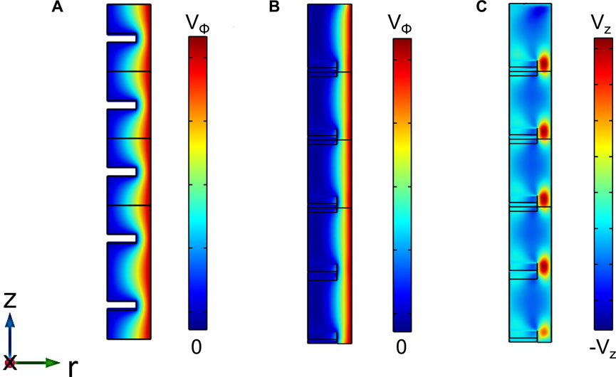
FIGURE 2. Simulated flow profiles of a Newtonian fluid in different ridged geometries: (A) horizontal (B, C) angled ridges with θ = 45°. Colourbar shows the velocity in the respective directions indicated by the subscript (ϕ for azimuthal and z for axial). Here the azimuthal and axial velocities are of the order of ∼ 10–3 and 10–4 in m s−1, respectively. The axial velocities in (C) are negative within the ridges and are positive outside the ridges, indicating that the net flux is zero. For all these calculations, the curved geometries were approximated as flat (infinite radius) parallel plate geometries.
From the azimuthal velocity profiles in horizontal ridged geometry (Figure 2A) and angled ridged geometry (Figure 2B), we observed that the fluid flow profile penetrates into the gap between the ridges up to a certain extent. The extent of this penetration is denoted by a parameter that we call the penetration depth δ. This flow profile penetration influences the torque measured on the rheometer, thus, by measuring the torque, we can quantify the penetration depth as described in Section 2.4. We then characterised the penetration depth for different ridge spacing, ridge depth and ridge angles.
In the following subsections, we first evaluated the penetration depth for the two limiting cases of horizontal and vertical ridges, i.e., with ridges that are at 90° and 0° angles with respect to the vertical axis, respectively, both from experiments and numerical simulations. In the last subsection, we investigated the effect of different ridge angles on the penetration depth in the case of angled ridges.
3.1 Limiting case I: horizontal ridges
We measured the flow curves from the rotational tests on multiple horizontal ridged geometries. On a log-log scale, the torque M increased linearly with the rotation rate Ω for over four orders of magnitude in rotation rate (Figure 3A), indicating that the presence of ridges did not change the Newtonian shear rate dependence of the flow. To investigate the variations due to the different roughness parameters, we looked more closely on a linear scale (Figure 3B) and found that the measured torque decreases with increasing ridge depths D for a given ridge spacing S. This is due to the influence of the flow profile penetration on the measured torque, i.e., the penetration depth δ increases with ridge depth, leading to an increase in the effective gap size (per Eq. 3) and a decrease in the measured torque. It should be noted that in all these experiments, the rotation rates were low enough to avoid Taylor vortices.
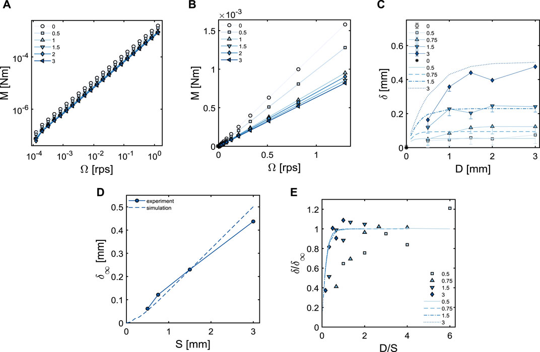
FIGURE 3. Experimental flow curves in (A) double logarithmic scale and (B) linear scale of castor oil measured in different horizontal ridged geometries. For all geometries, S = 3 mm and D is indicated in the legend. (C) Variation of δ in a horizontal ridged geometry with ridge depth for different ridge spacing (legend); experiments: symbols + lines, simulations: lines. (D) Plateau value of δ as a function of ridge spacing. A linear fit through the origin gives a slope of 0.17. (E) Master curve showing the collapse of the curves onto one exponential function (Eq. 5) when plotted as normalised δ versus normalised ridge depth; ridge spacing is indicated in the legend; experiments: symbols, simulations: lines.
Figure 3C shows the penetration depth, obtained from the measured torques using Eq. 4, as a function of D for various ridge spacings S. We see that δ first increases with D, but then levels off to a plateau that depends on the value of S. Hence, the flow can penetrate between the ridges only up to a certain maximum depth, δ∞, which increases approximately linearly with the ridge spacing S (Figure 3D).
To complement the experiments and to gain more insight into the flow profile penetration, Finite Element simulations were performed. The geometries were recreated as described in Section 2.3, and the curvature of the geometry was neglected. For this geometry, the only non-zero velocity component is in the azimuthal (ϕ) direction, while all gradients in the ϕ-direction are zero. The pressure was also constant in this case. The simulated penetration depths as a function of different ridge depths and ridge spacings are plotted in Figure 3C as dashed lines. The experimental and simulation results match quite well, especially at larger D. Similar to the experiments, the δ values plateau after a certain ridge depth; and the plateau value δ∞ exhibits a linear increase with S, see Figure 3D.
For a solid cylinder case (S = 0), δ∞ must be zero as the fluid cannot penetrate into a solid cylinder, and therefore, we would normally expect δ∞ to scale linearly with the ridge spacing and the linear plot (dashed line in Figure 3D) to extrapolate to the origin. However, this is not observed and δ∞ seems to deviate from the linear dependence on S at small ridge spacings below 0.5 mm. This is because in this small S limit, the ridge spacing becomes comparable to the ridge width, which also starts to play a role in determining the penetration depth. Strikingly, the normalised penetration depth δ/δ∞ for different ratios of D/S collapses onto a master curve (Figure 3E). The collapse to the master curve is observed to be satisfactory for the numerical data, whereas it is poor in case of the experimental data, particularly in the small D limit. The underlying reasons behind this observation are discussed in the subsequent paragraph. This master curve can be described by a simple exponential function:
The initial part of this master curve, corresponding to small D or large S, can be linearized to give δ/δ∞ ≈ kD/S. It is expected that δ → D in this regime, so that we expect k = 1/k2, with k2 being the slope of the curve of δ∞ versus S. We find 1/k2 ≈ 5.88 from Figure 3D, which is indeed close to the value found for k. This can also be understood as follows: a static boundary layer is created due to the presence of the small ridges. The thickness of this static boundary layer is D − δ and it goes to zero as the spacing between the ridges becomes extremely large. The prefactor k takes into account the other geometric effects, most likely the effect from the other length scale, i.e., the ridge width W. At a constant ridge spacing S, the thicker the ridges, the lower will be the flow penetration, hence, δ will be smaller. We expect that as the ridge width increases, δ will be small and hence, δ∞ will also drop. If the normalised penetration depth δ/δ∞ decreases, then k increases. But if both δ and δ∞ decrease by the same factor, then δ/δ∞ will not change, hence, k will not change. Therefore, k can be written as a function of normalized W as: k = f (W/S).
The deviations of the experimental results from that of simulations are more pronounced at smaller D, and this is a consistent deviation for all ridge spacings. In order to understand these deviations, we explored different possible sources of error. First, we tried to reduce the end effects from the top and bottom conical parts of the geometry. Their contribution to the torque was calibrated on a solid cylindrical geometry and the torques for the ridged geometries were corrected for these end effects. However, deviations were still observed, suggesting the presence of additional sources of error. For instance, small inaccuracies during the fabrication of the geometries have a bigger influence at smaller cutouts. Likewise, the measurement of the actual dimensions of the 3D printed geometries such as the inner and the outer radii, as well as the length of the geometries is challenging due to the small size of the geometries. Additionally, boundary conditions like wall slip are uncontrolled in the experiments, especially for large S and small D, which may further contribute to small errors. Another possibility is that small air bubbles may be trapped between the ridges, especially for small ridge spacings, and can lead to occasional deviations in the results. Finally, we want to highlight the additional physics that can come into play at ridge spacing below 0.5 mm (small S limit), where the ridge spacing becomes comparable to the ridge width. The ridge width is another important length scale that is relevant in case of ridges with small spacings. However, the analysis of the effect of different ridge width is beyond the scope of the present work. Due to these reasons, we took the plateau value of delta (δ∞) in experimental results as the average of the last three δ values. By linking the experiments and the simulations, it is possible to determine how changing the D and S of the ridges changes the penetration depth δ.
3.2 Limiting case II: vertical ridges
The second limiting case for patterned walls is a cylindrical geometry with vertical ridges. Here, we show only the numerical results in the limit where the curvature can be neglected (i.e., for large cylinder radii), see Section 2.3. In this case, the fluid velocity has components both in the ϕ and the r-directions, and gradients in the z-direction are zero.
The penetration depth for vertical ridges with different ridge depths and ridge spacings were calculated as described in Section 2.4 and plotted in Figure 4A. The flow profiles penetrate more deeply in between the ridges with increasing ridge depth and spacing, therefore, δ increases. This behaviour is similar to what was observed in the case of horizontal ridges, however, the penetration depth values in vertical ridges are smaller than for the horizontal ridge case because the main flow direction is perpendicular to the ridges while for the horizontal ridges, the flow is along the ridges. In contrast to the horizontal ridge case, we see two (quasi-)plateau values of δ as a function of D: the first plateau value is at around D = 0.5 mm, where the ridge depth is close to the ridge width and most likely, the plateau value is attributed to the influence of the ridge width. The second plateau value is at large ridge depths similar to what was observed in the case of horizontal ridges. We consider the second plateau value to be δ∞.
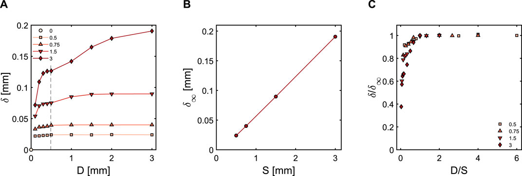
FIGURE 4. (A) Variation of simulated δ in a vertical ridged geometry (considered as flat plate) with ridge depth and different ridge spacing (legend). Here we see a first plateau at the dashed line, followed by a second plateau at large ridge depths. (B) Plateau value of δ as a function of ridge spacing (slope = 0.065). (C) Normalised δ as a function of normalised ridge depth; ridge spacing is indicated in the legend.
δ∞ increases linearly with the ridge spacing S (Figure 4B), but the slope is about 2.5 times smaller in comparison to the horizontal ridge case. Additionally, the linear plot of δ∞ against S does not precisely extrapolate to the origin and there seems to be non-linear dependence at small ridge spacings below 0.5 mm.
The normalised penetration depth δ/δ∞ for different ratios of D/S collapses onto a master curve (Figure 4C). However, a single exponential fit does not work so well compared to what was seen in the horizontal ridge case, suggesting a two-step function fit. This is most likely due to the presence of two plateaus in the δ vs. D variation (Figure 4A). For S ≫ D, i.e., for small values of D/S, we expect δ → D; the plot of δ/δ∞ against D/S is linear in this region and the slope of this plot is inversely related to the slope of the variation of δ∞ with S.
Finally, it is worth noting that the relationship between δ∞ and S could potentially depend on the ridge width W and the gap size Ro − Ri. These are a few additional length scales to explore, which may give different regimes (for example: two plateau values in δ vs. D plot). The current plots shown are for S ≫ W. This is a substantially general rescaling that to our knowledge has not been reported in the literature, and it is helpful to get a better understanding of the angled ridge case, as discussed below.
3.3 Angled ridge case
Having studied the two limiting cases, we now investigate the influence of geometries with ridges at finite angles on the flow behaviour of a Newtonian fluid. All the angled geometries have the same ridge spacing and ridge depth, and the ridge angles vary from 0° to 60° with 10° intervals. For different angles, the torque required to sustain a certain Ω shows a linear dependence on the rotation rate even at higher rotation rates, indicating that the angled ridges do not affect the Newtonian shear rate dependence of the flow (Figure 5A). However, the slope of the torque versus rotation rate changes as a function of ridge angle (Figure 5B), indicating that the extent of flow profile penetration into the gap between the ridges changes with the angle. To examine the effect of different angles, we calculated the penetration depths from the M vs. Ω relationship as previously done for the limiting cases.
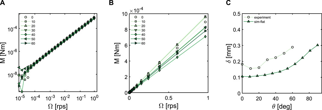
FIGURE 5. Experimental flow curves in (A) double logarithmic scale and (B) linear scale of castor oil measured in angled ridged geometries with ridges at various θ (indicated in the legend) with respect to the vertical axis. For all geometries, ridge spacing S = 2 mm and ridge depth D = 1 mm. (C) Variation of δ as a function of the ridge angle. All the simulation predictions are for a flat geometry corresponding to large cylinder radii, and with S = 2 mm and D = 1 mm.
Interestingly, δ shows a monotonic dependence on the ridge angle (Figure 5C) and increases as θ increases, with the largest δ for the horizontal ridges (θ = 90°). There are a few outliers at smaller ridge angles. One of the plausible reasons is δ is derived from the assumption that there is a shear stress only in the azimuthal direction. In reality, there is a normal force (and hence, a shear stress in the axial direction) and it is not clear whether the normal force is completely decoupled from the azimuthal shear stress.
We compare our experimental findings with numerical results. In the case of angled ridges, the velocity has non-zero components in the ϕ, r, and z-directions, and also the velocity gradients in all three directions are non-zero, so, a full 3D calculation is necessary. As we restrict ourselves to a flat geometry (corresponding to large cylinder radii), we can make use of symmetries to limit the computational domain. In particular, we model a domain with five ridges (see Supplementary Figure S1A) and impose a zero-outflow condition at the bottom and top of the domain, and periodic boundary conditions along the azimuthal directions. To reduce the influence of end effects, we exclude the top and bottom regions when calculating the average shear stress on the wall.
As shown in Figure 5C, the simulated δ values for angled ridges in the flat plate regime exhibit a similar trend as the experimental values, with δ monotonically increasing as the angle increases from 0° (vertical) to 90° (horizontal). However, the experimental values are systematically higher than the simulated ones, with an offset of ∼ 0.1 mm. It is not clear what determines this offset; potential factors include partial wall slip (which would reduce the measured torque) or curvature effects. Although we have previously seen that the effect of curvature is negligible in horizontal and vertical ridges, it is highly unlikely that the curvature will have an effect in the case of angled ridges (refer to Section 2.3 for details). Likewise, the presence of even a small amount of wall slip suppresses the shear rate because in such a slip situation, there would be a large effective gap size which lowers the torque. A lower torque would then result in higher penetration depth, as observed in the case of experiments. It is important to note that the flows in two directions (azimuthal and axial) are independent of each other; the superimposition of an axial flow along the symmetry axis of the rotating inner cylinder would not change the expression for the torque M. Such axial flow components cannot be the source of the discrepancy either.
4 Conclusion
Our work presents a novel approach to investigate wall roughness boundary conditions by considering a penetration depth δ. We have introduced rough textured surfaces in the form of ridged geometries that can be readily fabricated using 3D printing technique. This way of patterning offers the freedom to explore a wide range of wall roughness features that can be easily characterised to study their influence on the fluid flow behaviour.
We have considered three types of ridged geometries: one featuring horizontal ridges, another with vertical ridges and a third with angled ridges on the wall of the geometry. These ridged geometries introduce (an anisotropic) wall roughness, leading to non-trivial boundary conditions for the fluid flow. We have demonstrated that this roughness has an influence on the flow behaviour in case of simple Newtonian fluids even at a low Reynolds number. More specifically, due to the presence of ridges, the flow profiles penetrate in between the ridges and the extent of this penetration can be captured as penetration depth δ. The penetration depth captures the effective behaviour of the decaying fluid velocity profile into the roughness. We have measured the dependence of this penetration depth on various roughness parameters such as D, S, and θ by using standard rheological measurements on Newtonian fluids. For horizontal ridges with varying depth and spacing, we show that the penetration depth collapses onto a simple exponential master curve δ = δ∞(1 − e−kD/S). A similar variation is observed for vertical ridges, but the magnitude of the penetration depth is smaller than for the horizontal ridges. The penetration depth for angled ridges is found to lie quantitatively between that of horizontal and vertical ridges. In the context of a concentric cylinder geometry, our work indicates that the wall roughness can be effectively modelled by a simpler no-slip wall condition at a different effective radius. Numerical simulations support our experimental observations.
As a follow-up work, we intend to use these ridged geometries in a rheo-MRI setup to measure fluid velocity profiles, with a particular emphasis on non-Newtonian fluids. This study will enable us to delve deeper into understanding the relationship between different velocity profiles in diverse fluids and their consequent effects on the overall fluid flow.
Data availability statement
The raw data supporting the conclusion of this article will be made available by the authors, without undue reservation.
Author contributions
AM: Methodology, Formal Analysis, Investigation, Software, Visualization, Validation, Data curation, Writing–original draft, Writing–review and editing. LK: Formal Analysis, Investigation, Methodology, Software, Writing–review and editing. JvG: Formal Analysis, Investigation, Methodology, Software, Resources, Writing–review and editing, Conceptualization, Funding acquisition, Project administration, Supervision. JD: Conceptualization, Funding acquisition, Methodology, Project administration, Resources, Supervision, Writing–review and editing.
Funding
The author(s) declare that financial support was received for the research, authorship, and/or publication of this article. This work is a part of the Industrial Partnership Programme Controlling Multiphase Flow (Project No. 680-91-012) that is carried out under an agreement between Shell, Unilever Research and Development B.V., Evodos and the Netherlands Organisation for Scientific Research (NWO). This project is co-funded by NWO and TKI-E&I with the supplementary grant “TKI-Toeslag” for Top Consortia for Knowledge and Innovation (TKI’s) of the Ministry of Economic Affairs and Climate Policy. This work is within the framework of the Institute of Sustainable Process Technology.
Acknowledgments
The authors thank all the industrial partners and collaborators for their useful comments. We thank Bob Mulder for introducing 3D printing in rheology to us.
Conflict of interest
The authors declare that the research was conducted in the absence of any commercial or financial relationships that could be construed as a potential conflict of interest.
The author(s) declared that they were an editorial board member of Frontiers, at the time of submission. This had no impact on the peer review process and the final decision.
Publisher’s note
All claims expressed in this article are solely those of the authors and do not necessarily represent those of their affiliated organizations, or those of the publisher, the editors and the reviewers. Any product that may be evaluated in this article, or claim that may be made by its manufacturer, is not guaranteed or endorsed by the publisher.
Supplementary material
The Supplementary Material for this article can be found online at: https://www.frontiersin.org/articles/10.3389/fphy.2024.1347878/full#supplementary-material
References
1. Bottaro A. Flow over natural or engineered surfaces: an adjoint homogenization perspective. J Fluid Mech (2019) 877:1–91. doi:10.1017/jfm.2019.607
2. Chen Y, Zhang C, Shi M, Peterson GP. Slip boundary for fluid flow at rough solid surfaces. Appl Phys Lett (2012) 100:0741021–0741024. doi:10.1063/1.3685490
3. Gao W, Zhang X, Han X, Shen C. Role of solid wall properties in the interface slip of liquid in nanochannels. Micromachines (2018) 9:6631–66311. doi:10.3390/mi9120663
4. Achdou Y, Pironneau O, Valentin F. Effective boundary conditions for laminar flows over periodic rough boundaries. J Comput Phys (1998) 147:187–218. doi:10.1006/jcph.1998.6088
5. Zampogna GA, Magnaudet J, Bottaro A. Generalized slip condition over rough surfaces. J Fluid Mech (2019) 858:407–36. doi:10.1017/jfm.2018.780
6. Zampogna GA, Naqvi SB, Magnaudet J, Bottaro A. Compliant riblets: Problem formulation and effective macrostructural properties. J Fluids Structures (2019) 91:1027081–10270814. doi:10.1016/j.jfluidstructs.2019.102708
7. Djenidi L, Liandrat J, Anselmet F, Fulachier L. Numerical and experimental investigation of the laminar boundary layer over riblets. Appl Scientific Res (1989) 46:263–270. doi:10.1007/bf00404823
8. Choi H, Moin P, Kim J. On the effect of riblets in fully developed laminar channel flows. Phys Fluids A: Fluid Dyn (1991) 3:1892–1896. doi:10.1063/1.857918
9. Djenidi L, Anselmet F, Liandrat J, Fulachier L. Laminar boundary layer over riblets. Phys Fluids (1994) 6:2993–2999. doi:10.1063/1.868429
10. Raayai-Ardakani S, McKinley GH. Geometric optimization of riblet-textured surfaces for drag reduction in laminar boundary layer flows. Phys Fluids (2019) 31:053601–0536017. doi:10.1063/1.5090881
11. Raayai-Ardakani S, McKinley GH. Geometry mediated friction reduction in Taylor-Couette flow. Phys Rev Fluids (2020) 5:1241021–12410225. doi:10.1103/physrevfluids.5.124102
12. Rosenberg BJ, Van Buren T, Fu MK, Smits AJ. Turbulent drag reduction over air- and liquid-impregnated surfaces. Phys Fluids (2016) 28:0151031–0151038. doi:10.1063/1.4939272
13. Sundin J, Zaleski S, Bagheri S. Roughness on liquid-infused surfaces induced by capillary waves. J Fluid Mech (2021) 915:R61–R612. doi:10.1017/jfm.2021.241
14. Maynes D, Jeffs K, Woolford B, Webb BW. Laminar flow in a microchannel with hydrophobic surface patterned microribs oriented parallel to the flow direction. Phys Fluids (2007) 19:0936031–09360312. doi:10.1063/1.2772880
15. Davies J, Maynes D, Webb BW, Woolford B. Laminar flow in a microchannel with superhydrophobic walls exhibiting transverse ribs. Phys Fluids (2006) 18:0871101–08711011. doi:10.1063/1.2336453
16. Ou J, Perot B, Rothstein JP. Laminar drag reduction in microchannels using ultrahydrophobic surfaces. Phys Fluids (2004) 16:4635–4643. doi:10.1063/1.1812011
17. Watanabe K, Udagawa Y, Udagawa H. Drag reduction of Newtonian fluid in a circular pipe with a highly water-repellent wall. J Fluid Mech (1999) 381:225–238. doi:10.1017/s0022112098003747
18. van den Berg TH, Luther S, Lathrop DP, Lohse D. Drag reduction in bubbly Taylor-Couette turbulence. Phys Rev Lett (2005) 94:044501–044504. doi:10.1103/physrevlett.94.044501
19. Bechert DW, Bartenwerfer M. The viscous flow on surfaces with longitudinal ribs. J Fluid Mech (1989) 206:105–129. doi:10.1017/s0022112089002247
20. Bechert DW, Bruse M, Hage W, Meyer R. Fluid mechanics of biological surfaces and their technological application. Naturwissenschaften (2000) 87:157–171. doi:10.1007/s001140050696
21. Bixler GD, Bhushan B. Fluid drag reduction with shark-skin riblet inspired microstructured surfaces. Adv Funct Mater (2013) 23:4507–4528. doi:10.1002/adfm.201203683
22. Abdulbari HA, Yunus R. M., Abdurahman N. H., Charles A. Going against the flow—a review of non-additive means of drag reduction. J Ind Eng Chem (2013) 19:27–36. doi:10.1016/j.jiec.2012.07.023
23. Soleimani S, Eckels S. A review of drag reduction and heat transfer enhancement by riblet surfaces in closed and open channel flow. Int J Thermofluids (2021) 9:1000531–10005315. doi:10.1016/j.ijft.2020.100053
24. Cafiero G, Iuso G. Drag reduction in a turbulent boundary layer with sinusoidal riblets. Exp Therm Fluid Sci (2022) 139:1107231–11072315. doi:10.1016/j.expthermflusci.2022.110723
25. Walsh MJ. Turbulent boundary layer drag reduction using riblets (1982). AIAA Paper No. 82–0169. doi:10.2514/6.1982-169
26. Walsh MJ. Riblets as a viscous drag reduction technique. AIAA J (1983) 21:485–486. doi:10.2514/3.60126
27. Walsh MJ, Lindemann AM. Optimization and application of riblets for turbulent drag reduction (1984). AIAA Paper No.84–0347. doi:10.2514/6.1984-347
28. Walsh MJ, Walsh MJ. Viscous Drag Reduction in Boundary Layers. SAIAA, 123 (1990), 203–261. doi:10.2514/5.9781600865978.0203.0261
29. Bechert DW, Bruse M, Hage W, van der Hoeven JGT, Hoppe G. Experiments on drag-reducing surfaces and their optimization with an adjustable geometry. J Fluid Mech (1997) 338:59–87. doi:10.1017/s0022112096004673
30. Grüneberger R, Hage W. Drag characteristics of longitudinal and transverse riblets at low dimensionless spacings. Exp. in Fluids (2011) 50:363–373. doi:10.1007/s00348-010-0936-7
31. Raayai-Ardakani S, McKinley GH. Drag reduction using wrinkled surfaces in high Reynolds number laminar boundary layer flows. Phys Fluids (2017) 29:0936051–09360516. doi:10.1063/1.4995566
32. Nickerson CS, Kornfield JA. A “cleat” geometry for suppressing wall slip. J Rheol. (2005) 49:865–874. doi:10.1122/1.1917846
33. Owens CE, Hart AJ, McKinley GH. Improved rheometry of yield stress fluids using bespoke fractal 3D printed vanes. J Rheol. (2020) 64:643–662. doi:10.1122/1.5132340
34. Luchini P, Manzo F, Pozzi A. Resistance of a grooved surface to parallel flow and cross-flow. J Fluid Mech (1991) 228:87–109. doi:10.1017/s0022112091002641
35. Bechert DW, Bartenwerfer M, Hoppe G, Reif WE. Drag reduction mechanisms derived from shark skin. Proceedings ICAS (1986) 2:1044–1068.
36. Bechert DW, Bartenwerfer M, Hoppe G. Turbulent drag reduction by nonplanar surfaces – a survey on the research at TU/DLR Berlin. ed. Gyr A, In: Proceedings IUTAM Symposium, editor. Structure of turbulence and drag reduction. Berlin, Heidelberg: Springer-Verlag (1989). p. 525–543.
37. Woolford B, Maynes D, Webb BW. Liquid flow through microchannels with grooved walls under wetting and superhydrophobic conditions. Microfluid Nanofluid (2009) 7:121–135. doi:10.1007/s10404-008-0365-6
38. Launder BE, Li S. A numerical study of riblet effects on laminar flow through a plane channel. Appl Scientific Res (1989) 46:271–279. doi:10.1007/bf00404824
39. Jung YC, Bhushan B. Biomimetic structures for fluid drag reduction in laminar and turbulent flows. J Phys: Condens Matter (2009) 22:0351041–0351049. doi:10.1088/0953-8984/22/3/035104
40. Mohammadi A, Floryan JM. Groove optimization for drag reduction. Phys Fluids (2013) 25:113601 1–25. doi:10.1063/1.4826983
41. Mohammadi A, Floryan JM. Pressure losses in grooved channels. J Fluid Mech (2013) 725:23–54. doi:10.1017/jfm.2013.184
42. Liu Y, Li J, Smits AJ. Roughness effects in laminar channel flow. J Fluid Mech (2019) 876:1129–1145. doi:10.1017/jfm.2019.603
44. Callaghan PT. Rheo-NMR: nuclear magnetic resonance and the rheology of complex fluids. Rep Prog Phys (1999) 62:599–670. doi:10.1088/0034-4885/62/4/003
45. Coussot P. Progress in rheology and hydrodynamics allowed by nmr or mri techniques. Exp. in Fluids (2020) 61:2071–20720. doi:10.1007/s00348-020-03037-y
46. COMSOL Multiphysics® version 5.6. Stockholm, Sweden: COMSOL AB (2023). Available at: http://www.comsol.com.
47. Feynman RP, Leighton RB, Sands M. The Feynman Lectures on physics, vol. II: mainly electromagnetism and matter. edn. The New Millennium: Basic Books (2011).
48. Landau LD, Lifshitz EM. Fluid mechanics. 2nd edn. Pergamon press (1987). p. 44–94. Chapter ii - viscous fluids.
50. Dean B, Bhushan B. Shark-skin surfaces for fluid-drag reduction in turbulent flow: a review. Phil Trans R Soc A: Math Phys Eng Sci (2010) 368:4775–4806. doi:10.1098/rsta.2010.0201
Keywords: rough boundaries, wall effects, patterned geometries, periodic roughness patterns, fluid flow penetration, complex flow profiles, stress-based measurements
Citation: Majhi A, Kool L, van der Gucht J and Dijksman JA (2024) Quantitative coarse graining of laminar fluid flow penetration in rough boundaries. Front. Phys. 12:1347878. doi: 10.3389/fphy.2024.1347878
Received: 01 December 2023; Accepted: 26 February 2024;
Published: 14 March 2024.
Edited by:
Felix Sharipov, Federal University of Paraná, BrazilReviewed by:
Guoxiang Hou, Huazhong University of Science and Technology, ChinaEngin Gedik, Karabük University, Türkiye
Badr Kaoui, University of Technology Compiegne, France
Jian Wu, Harbin Institute of Technology, China
Copyright © 2024 Majhi, Kool, van der Gucht and Dijksman. This is an open-access article distributed under the terms of the Creative Commons Attribution License (CC BY). The use, distribution or reproduction in other forums is permitted, provided the original author(s) and the copyright owner(s) are credited and that the original publication in this journal is cited, in accordance with accepted academic practice. No use, distribution or reproduction is permitted which does not comply with these terms.
*Correspondence: Joshua A. Dijksman, j.a.dijksman@uva.nl