 Dongsheng Zheng
 Yuli Yang
- 1School of Electronics, Peking University, Beijing, China
- 2School of Engineering, University of Lincoln, Lincoln, United Kingdom
In this work, a novel scheme is proposed to enhance the self-interference (SI) cancellation in full-duplex communications. Beyond conventional SI cancellation schemes that rely on the SI suppression, our proposed scheme exploits periodic antenna switching to generate the pseudo-Doppler effect, thus completely removing the SI at the fundamental frequency. In this way, the desired signal is readily obtained through a low-pass filter. For the purpose of performance evaluation, the SI cancellation capability is defined as the difference between the output signal-to-interference-plus-noise ratio (SINR) and the input SINR. Theoretical formulations and numerical results validate that our pseudo-Doppler aided scheme has higher SI cancellation capability than the conventional SI suppression schemes. Moreover, the impact of the SI suppression achieved by conventional schemes and the influence of antenna switching timing difference on the practical implementation of the proposed scheme are investigated, to further substantiate the validity of our pseudo-Doppler aided SI cancellation.
1 Introduction
In wireless communications, the Doppler spread, resulting from a relative motion between a pair of transmitter and receiver, is deemed to be a destructive component if the relative motion is very fast, as it is likely to cause frequency dispersion and inter-carrier interference, which will result in poor communication performance (Wang et al., 2006). However, the pseudo-Doppler effect, generated through a change in the wavelength or frequency of a signal received at the observer who is in pseudo motion relative to the signal source, has been favourably exploited by radar and ultrasonic systems in the applications of direction finding, navigation, velocity measurement and vibration assessment (Won et al., 2019).
Motivated by this, we propose a pseudo-Doppler aided scheme to cancel the self-interference (SI) in full-duplex (FD) communications. Although the FD mode has been promoted as an attractive solution to double the spectral efficiency of wireless communications, the inherent SI at FD transceivers imposes a performance bottleneck for the FD operation (Tian et al., 2017; Ma et al., 2020). In the literature, many attempts have been made to remove the obstacle imposed by the strong SI, where various analog and digital techniques have been developed. In (Zhang et al., 2019), the SI was suppressed by 83 dB, including 45 dB from antenna isolation and 38 dB from adaptive multi-tap analog cancellation. In (Chung et al., 2015), the SI was suppressed by 103 dB, where the antenna isolation, analog and digital cancellations contributed 42 dB, 18 and 43 dB, respectively. In (Anttila et al., 2021), a real-time digital cancellation of 46 dB contributed towards a SI suppression of 103 dB.
The majority of conventional SI cancellation schemes rely on the SI suppression at the receiver (Sabharwal et al., 2014; Kolodziej et al., 2019). To the best of our knowledge, none of the SI cancellation schemes that have been reported can completely remove all the SI from the desired signal. In this work, we exploit the pseudo-Doppler effect to induce controllable frequency shift and completely remove the SI from the desired signal at the fundamental frequency.
The novelty and contribution of this work are three-fold.
• Approach: A novel SI cancellation scheme is proposed on the basis of pseudo-Doppler effect.
• Evaluation: The SI cancellation capability of the proposed scheme is formulated and compared with that of conventional schemes.
• Application: The conditions that the proposed scheme is preferred to conventional ones are investigated.
In the following, the pseudo-Doppler aided SI cancellation scheme is proposed based on the principle of pseudo-Doppler shift. Subsequently, its SI cancellation capability is theoretically analysed and compared with conventional SI cancellation schemes.
2 Motivation: pseudo-doppler shift
The pseudo-Doppler shift originated in radio systems for the purpose of direction finding (Earp and Godfrey, 1947). To cause a pseudo-Doppler shift, a rapid switching between the receive antennas (RAs) of an observer is utilised to imitate the relative motion between the transmit antenna (TA) of a target source and the observer. As shown in Figure 1, the observer’s N RAs are switched sequentially and circularly to receive the signals transmitted from the target source. As long as the switching is sufficiently fast, the target source’s direction will be found through the pseudo-Doppler effect caused by the switching. We remark that, the generation of pseudo-Doppler effect does not rely on an actual relative motion between the observer and the target source. For example, given that the distance between two adjacent RAs of the observer is d and the switching between them takes time τ, the switching cycle from RA 1 to RA N is equivalent to the target source moving towards the observer at a velocity of d/τ, while the switching cycle from RA N to RA 1 is equivalent to the target source moving away from the observer at d/τ.

FIGURE 1. An illustration of the pseudo-Doppler shift.
Given that the flat-fading channel coefficients spanning from the TA to the RAs are independent of each other, the observer’s received signal, denoted by y(t), is expressed as
where h(t) is the channel response and x(t) denotes the target source’s transmitted signal. The additive white Gaussian noise (AWGN) process ω(t) has a power spectrum density N0.
At the observer, the duration of a whole switching cycle from RA 1 to RA N is Ts and, thus, the identical switching interval of each RA is τ = Ts/N. As such, the channel response h(t) is formulated by a periodic function with period Ts as
where
As revealed by (4), the lth harmonic has frequency dispersion triggered by the switching between N RAs, l ≠ 0.
Further, the Fourier transform of the observer’s received signal y(t) is obtained by
where ∗ is the convolution operator. The Fourier transforms of the channel response h(t) and the AWGN ω(t) are
In essence, the pseudo-Doppler shift is induced by the periodic variation of channel coefficients between a pair of transmitter and receiver. Therefore, a periodic antenna switching at the transmitter or at both the transmitter and the receiver can also trigger the same frequency shift as that obtained in (5). Motivated by this, we propose a novel SI cancellation scheme to enhance the FD communication performance, by the aid of a pseudo-Doppler shift, in next Section.
3 Pseudo-doppler aided SI cancellation
For the receiver to retrieve the desired signal in a FD transmission, the majority of conventional SI cancellation schemes, e.g., Zhang et al. (2019); Chung et al. (2015); Anttila et al. (2021), rely on the SI suppression, where the SI is firstly reconstructed and then subtracted from the received signal. Different from this design, we will exploit the pseudo-Doppler effect to completely remove the SI from the desired signal at the fundamental frequency.
Consider the communications between a pair of FD transceivers, Alice and Bob, as shown in Figure 2, where both Alice and Bob periodically switch their antennas to generate the pseudo-Doppler effect. A switching cycle of duration Ts is divided into two intervals: In the first half cycle, i.e., t ∈ [kTs, (k + 1/2)Ts), Antennas I and II of a transceiver is used as its TA and RA, respectively; in the second half cycle, i.e., t ∈ [(k + 1/2)Ts, (k + 1)Ts), Antennas I and II of a transceiver is used as its RA and TA, respectively,
where hDS(t) and hSI(t) are the channel responses to the desired signal, denoted by xDS(t), and the SI, denoted by xSI(t), respectively.
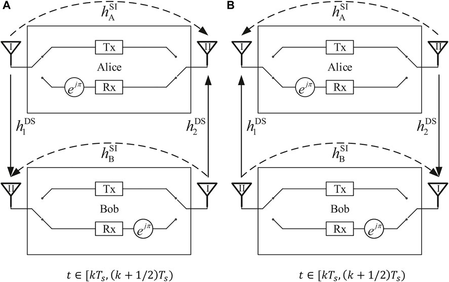
FIGURE 2. The system structure of pseudo-Doppler aided SI cancellation: (A) t ∈ [kTs (k + 1/2)Ts), (B) t ∈ [(k + 1/2)Ts (k + 1)Ts),
Next, we will focus on the SI cancellation at Bob, as the SI cancellation at Alice can be analysed in the same way. As regards the periodic antenna switching at both Alice and Bob, Bob’s channel responses to his desired signal and SI can be written as
and
respectively, where
Referring to (3) and (4), we have the coefficients for the Fourier series of hDS(t) as
Similarly, the coefficients for the Fourier series of hSI(t) are
As such, the SI channel response at the fundamental frequency,
Then, referring to (5), we obtain the frequency-domain expression of Bob’s received signal y(t) given in (6) as
where XDS(f) and XSI(f) denote the Fourier transforms of the desired signal xDS(t) and the SI xSI(t), respectively.
As shown in (11), the SI has been completely removed from the received signal at the fundamental frequency and, therefore, we may readily obtain the desired signal using a low-pass filter at the fundamental frequency. To guarantee that the desired signal is perfectly filtered from the received signal, the antenna switching cycle duration Ts should be set to Ts⩽1/(2B), i.e., the unit pseudo-Doppler shift fs⩾2B, where B is the bandwidth of the desired signal.
It is noted that the channel reciprocity is of critical importance to a complete removal of the SI at the fundamental frequency. Herein, we further validate the assumption of channel reciprocity over the SI path(s). In general, there are three types of SI-coupling path(s): the line-of-sight (LoS) path, the fixed-reflection paths, and the moving-reflection paths (Kolodziej et al., 2019). For the LoS path and the fixed-reflection paths, accurate calibration of the transceiver radio frequency chains guarantees the channel reciprocity. For the moving-reflection paths, the channel reciprocity can also be achieved within the coherence time. In practice, the efficacy of our pseudo-Doppler aided SI cancellation can be guaranteed within current frame-based wireless systems, where the frame length is determined by the coherence time.
4 Performance evaluation
In this section, the SI cancellation capability of our pseudo-Doppler aided scheme is investigated and compared with that of conventional SI cancellation schemes, based on which the conditions that our scheme is preferred to conventional ones are quantified in terms of outage probability. Herein, the block fading channel model is adopted, where the channel coefficients remain constant within a coherence time and change to an independent status in the next coherence time. This process is repeated for each coherent time and, therefore, the coherence time (i.e., the velocity of a moving terminal) is not an explicit factor in the channel model.
4.1 SI cancellation capability
The SI cancellation capability of the proposed pseudo-Doppler aided scheme is defined in dB as
where
As shown in (11), the desired signal can be filtered free of the SI at the fundamental frequency l = 0. Hence, the output SINR γPD is formulated as
where Pt is the transmit power. Herein, the channel coefficients
and
where G and ϕ are the path-loss constant and exponent, respectively. The distance between Alice and Bob is dDS. Moreover, the small-scale fading
Substituting (14) and (15) into (13), we have
which follows an exponential distribution with mean
Thus, the probability density function (pdf) of γPD is
The SINR without any SI cancellation, γin, is expressed as
where
Based on (Kwon et al., 2010, Eq. 5), the cumulative distribution function (cdf) of γin is obtained by
Then, the mean SINR without any SI cancellation is
where
As a result, the SI cancellation capability of our pseudo-Doppler aided scheme is obtained by substituting (17) and (21) into (12), which is compared with the SI cancellation capability of conventional schemes in Figure 3. The conventional SI cancellation capability is expressed in dB as
where
with η for the SI suppression factor. More specifically, the mean residual SI to noise power ratio is
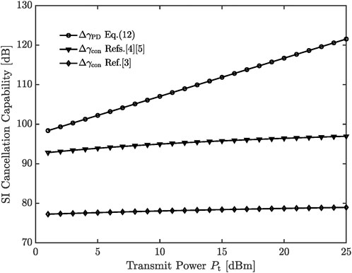
FIGURE 3. The SI cancellation capability comparisons between the pseudo-Doppler aided scheme and conventional schemes.
In Figure 3, the distance between Alice and Bob, dDS = 100 m. The distance between Antennas I and II, dSI = 0.05 m. The path-loss constant G = −31.5dB, and the path-Loss exponent ϕ = 3. The AWGN power spectral density N0 = −174 dBm/Hz, and the bandwidth B = 5 MHz. As shown in this figure, our pseudo-Doppler aided scheme has a much stronger capability in the SI cancellation than the conventional schemes that rely on the SI suppression.
4.2 Impact of SI suppression factor
With the rapid development of signal processing technologies, a growth is anticipated in the SI suppression factor of conventional schemes. Herein, the impact of the SI suppression factor on the application of our pseudo-Doppler aided scheme is investigated in terms of the output SINR outage probability.
The outage probability of output SINR is defined as the probability that the output SINR falls below a predetermined threshold γ0. Hence, the outage probability of the output SINR γPD in our pseudo-Doppler aided scheme is
where the pdf
where the cdf of γcon,
Given the threshold γ0, our pseudo-Doppler aided scheme is preferred to conventional ones in the condition that Pr (γPD⩽γ0) < Pr (γcon⩽γ0), where we have
In other words, our pseudo-Doppler aided scheme outperforms conventional ones when their SI suppression factor is lower than η0 defined in (27). The SI suppression factor η0 is plotted versus the distance between Alice and Bob, dDS, in Figure 4A, where the transmit power Pt = 15 dBm. Meanwhile, η0 is plotted versus the transmit power Pt in Figure 4B, where the distance dDS = 500 m. The other simulation parameters are set the same as those in Figure 3.
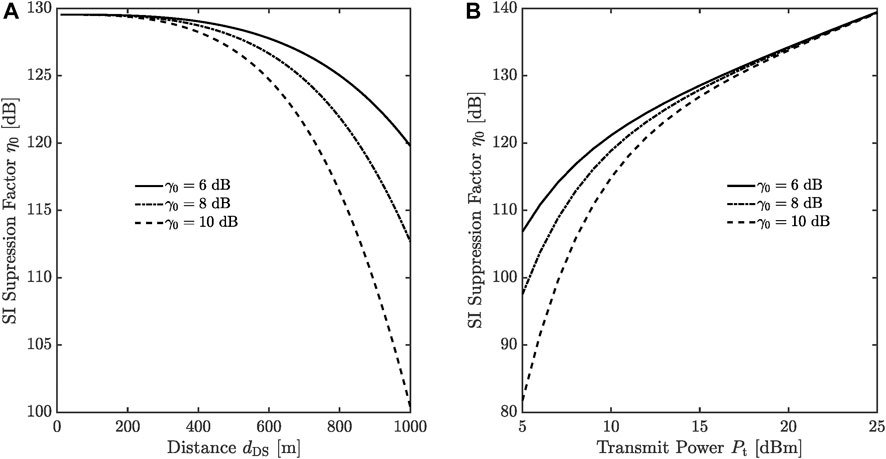
FIGURE 4. The SI suppression factor η0: (A) versus the distance dDS, (B) versus the transmit power Pt.
As shown in these figures, η0 decreases as the threshold γ0 or the distance dDS increases, which implies that conventional schemes need lower SI suppression factors to compete with the SI cancellation capability of the proposed scheme if there is a higher requirement on the output SINR or a larger distance between Alice and Bob. However, the SI suppression factors in Figure 4 are still too high for the SI cancellation schemes that have been reported to achieve.
In addition, η0 increases as the transmit power Pt increases, which can be derived from the definition of η0 in (27) as well. The main reason behind this is that our pseudo-Doppler aided scheme completely removes the SI from the desired signal at the fundamental frequency, while the residual SI in conventional cancellation schemes increases with the increase in the transmit power Pt.
4.3 Impact of antenna switching timing difference
From the design presented in Section 3, we may find that Alice and Bob need to synchronise their antenna switching timing in the pseudo-Doppler aided SI cancellation. However, due to sync error, there might be a timing difference between them in practice. Given that both Alice’s and Bob’s antenna switching cycles are Ts, the timing difference, denoted by ΔT, is illustrated in Figure 5, where hba is the channel coefficient from Alice’s Antenna a to Bob’s Antenna b, a, b ∈ {1, 2}. In this regard, Bob’s channel response to Alice’s signal is formulated as.

FIGURE 5. Alice’s and Bob’s timing sequences of antenna switching, in the presence of timing difference.
The Fourier series of
Where
On the other hand, Bob’s channel response to the SI in the presence of timing difference is the same as that without timing difference, i.e., given by (8), which indicates that the timing difference has no influence on the SI removal at the fundamental frequency l = 0.
Thus, the mean SINR at the output of the low-pass filter can be derived as
Obviously, the mean SINR
5 Discussion
In this work, a novel SI cancellation scheme, referred to as pseudo-Doppler aided cancellation, was proposed for FD communications to completely remove the SI from the desired signal and leave null residual SI at the fundamental frequency. In comparison to the conventional SI cancellation schemes that rely on the SI suppression, illustrative numerical results substantiated that the proposed scheme achieved much better performance in terms of SI cancellation capability.
Concerning the mixing of the desired signal and the SI at the pseudo-Doppler shifted frequencies, the development of advanced SI suppression technologies and the integration of our pseudo-Doppler aided SI cancellation with them are to be pursued for getting higher desired signal power at the receiver, aiming to further improve the output SINR.
Data availability statement
The raw data supporting the conclusions of this article will be made available by the authors, without undue reservation.
Author contributions
DZ and YY contributed to conception and design of the study. DZ performed the statistical analysis and wrote the first draft of the manuscript. YY revised the draft and approved the submitted version.
Conflict of interest
The authors declare that the research was conducted in the absence of any commercial or financial relationships that could be construed as a potential conflict of interest.
Publisher’s note
All claims expressed in this article are solely those of the authors and do not necessarily represent those of their affiliated organizations, or those of the publisher, the editors and the reviewers. Any product that may be evaluated in this article, or claim that may be made by its manufacturer, is not guaranteed or endorsed by the publisher.
References
Anttila, L., Lampu, V., Hassani, S., Campo, P., Korpi, D., Turunen, M., et al. (2021). Full-duplexing with sdr devices: Algorithms, fpga implementation, and real-time results. IEEE Trans. Wirel. Commun. 20, 2205–2220. doi:10.1109/TWC.2020.3040226
Chung, M., Sim, M., Kim, J., Kim, D., and Chae, C. (2015). Prototyping real-time full duplex radios. IEEE Commun. Mag. 53, 56–63. doi:10.1109/MCOM.2015.7263346
Earp, C., and Godfrey, R. (1947). Radio direction-finding by the cyclical differential measurement of phase. J. Institution Electr. Eng. 94, 705–721. doi:10.1049/ji-3a-2.1947.0091
Kolodziej, K., Perry, B., and Herd, J. (2019). In-band full-duplex technology: Techniques and systems survey. IEEE Trans. Microw. Theory Tech. 67, 3025–3041. doi:10.1109/TMTT.2019.2896561
Kwon, T., Lim, S., Choi, S., and Hong, D. (2010). Optimal duplex mode for df relay in terms of the outage probability. IEEE Trans. Veh. Technol. 59, 3628–3634. doi:10.1109/TVT.2010.2050503
Ma, M., Tian, S., Chen, Y., Wang, L., Yang, Y., Wan, L., et al. (2020). A prototype of co-frequency co-time full duplex networking. IEEE Wirel. Commun. 27, 132–139. doi:10.1109/MWC.001.1800565
Sabharwal, A., Schniter, P., Guo, D., Bliss, D., Rangarajan, S., Wichman, R., et al. (2014). In-band full-duplex wireless: Challenges and opportunities. IEEE J. Sel. Areas Commun. 32, 1637–1652. doi:10.1109/JSAC.2014.2330193
Tian, S., Ma, M., Yang, Y., and Jiao, B. (2017). Blind analog interference cancellation. IEEE Commun. Lett. 21, 1867–1870. doi:10.1109/LCOMM.2017.2694427
Wang, T., Proakis, J., Masry, E., and Zeidler, J. (2006). Performance degradation of ofdm systems due to Doppler spreading. IEEE Trans. Wirel. Commun. 5, 1422–1432. doi:10.1109/TWC.2006.1638663
Won, H., Isbel, K., Vanderburgh, L., Platt, J., Lee, W., Hong, Y., et al. (2019). Developing a direction-finding system and channel sounder using a pseudo-Doppler antenna array [education corner]. IEEE Antennas Propag. Mag. 61, 84–89. doi:10.1109/MAP.2019.2920047
Keywords: pseudo-doppler effect, self-interference cancellation, full-duplex communications, signal-to-interference-plus-noise ratio, timing sequence analysis
Citation: Zheng D and Yang Y (2022) Pseudo-doppler aided cancellation of self-interference in full-duplex communications. Front. Sig. Proc. 2:965551. doi: 10.3389/frsip.2022.965551
Received: 09 June 2022; Accepted: 30 June 2022;
Published: 16 August 2022.
Edited by:
Yonghui Li, The University of Sydney, AustraliaReviewed by:
Deshuang Zhao, University of Electronic Science and Technology of China, ChinaCopyright © 2022 Zheng and Yang. This is an open-access article distributed under the terms of the Creative Commons Attribution License (CC BY). The use, distribution or reproduction in other forums is permitted, provided the original author(s) and the copyright owner(s) are credited and that the original publication in this journal is cited, in accordance with accepted academic practice. No use, distribution or reproduction is permitted which does not comply with these terms.
*Correspondence: Yuli Yang, eXlhbmdAbGluY29sbi5hYy51aw==