Abstract
Dexterity robotic hands can (Cummings, 1996) greatly enhance the functionality of humanoid robots, but the making of such hands with not only human-like appearance but also the capability of performing the natural movement of social robots is a challenging problem. The first challenge is to create the hand’s articulated structure and the second challenge is to actuate it to move like a human hand. A robotic hand for humanoid robot should look and behave human like. At the same time, it also needs to be light and cheap for widely used purposes. We start with studying the biomechanical features of a human hand and propose a simplified mechanical model of robotic hands, which can achieve the important local motions of the hand. Then, we use 3D modeling techniques to create a single interlocked hand model that integrates pin and ball joints to our hand model. Compared to other robotic hands, our design saves the time required for assembling and adjusting, which makes our robotic hand ready-to-use right after the 3D printing is completed. Finally, the actuation of the hand is realized by cables and motors. Based on this approach, we have designed a cost-effective, 3D printable, compact, and lightweight robotic hand. Our robotic hand weighs 150 g, has 15 joints, which are similar to a real human hand, and 6 Degree of Freedom (DOFs). It is actuated by only six small size actuators. The wrist connecting part is also integrated into the hand model and could be customized for different robots such as Nadine robot (Magnenat Thalmann et al., 2017). The compact servo bed can be hidden inside the Nadine robot’s sleeve and the whole robotic hand platform will not cause extra load to her arm as the total weight (150 g robotic hand and 162 g artificial skin) is almost the same as her previous unarticulated robotic hand which is 348 g. The paper also shows our test results with and without silicon artificial hand skin, and on Nadine robot.
Introduction
The idea of automata was created very early in the human history more than 2,000 years ago. In China, Lu Ban made an artificial bird, which was able to fly with its wings (Needham, 1974). The Greek engineer, Ctesibius, applied knowledge of pneumatics and hydraulics to produce the first organ and water clocks with moving figures (Rosheim, 1994). After that, various mechanical designs were produced towards a trend of complexity and precision. “The Writer automaton” was built in the 1770s using 6,000 moving parts by Pierre Jaquet-Droz (Percy and Timbs, 1840). It can write any custom text up to 40 letters long, and text is coded on a wheel where characters are selected one by one. Actually, the writer basically fit the definition of a “Robot” from the Robot Institute of America (1979): “A reprogrammable, multifunctional manipulator designed to move materials, parts, tools, or specialized devices through various programmed motions for the performance of a variety of tasks.” However, its hands are not articulated. A human hand is the most articulated parts of the human body and grasping is one of the most common and important gestures that humans use when interacting with surrounding objects. The robotic hand is also a kind of automaton or robot. However, not much work about robotic hand can be found in the history until the first modern industrial robots “Unimates” in 1960s (Siciliano and Khatib, 2016). Since the creation of the first humanoid robot Eric (Riskin, 2016), researchers have been aiming to develop dexterity robotic hands for humanoid robots to make them grasp-like humans. Many different styles of robotic hands have been fabricated over the last 30 years. As electricity had been widely used as an easy-get and high-efficiency power resource, most of them are actuated by electrical motors or pneumatic motors (Siciliano and Khatib, 2016). It is undeniable that robotic hands have come close to replicating human hands. However, no such robotic hand works exactly like a human hand in terms of appearance and physical characteristics, which include movement and force. From the mechanical perspective, the main difficulty comes from two aspects, mechanism and actuation. First, the human hand has 15 movable joints, of which, some joints have more than one degree of freedom (DOF). These characteristics make it difficult to model and fabricate a human-like robotic hand. We also need to take into account the motion range of different joints as they have different limitations. Second, muscles and tendons drive our body motion in high efficiency (Woledge, 1998). There is currently no good solution to simulate the force with precise motions of fingers.
The state-of-the-art robotic hands usually have complex mechanical structures and control methods (Melchiorri et al., 2013) (Xu and Todorov, 2016). The development of 3D print technology, in some ways, has reduced the cost and complexity of making dexterity robotic hand. There are several robotic hands that can be 3D printed (Slade et al., 2015; ten Kate et al., 2017). However, according to their test report, the functionalities such as movable joint, DOF, and motion range, are not as good as these state-of-the-art robotic hands. Our robotic hand aims to mimic the grasping behavior of the human hand while staying simple in making and control of the robotic. With the help of Fused Deposition Modeling, 3D printed rigid endoskeleton (Tavakoli et al., 2017) and functional articulations non-assembly joint (Cali et al., 2012) are easy to apply to the robotic hand. It is also possible to integrate every joint into a single articulated hand 3D model. Human fingers have bones and tendons but do not contain muscles (Agur and Dalley, 2009). The muscles that move the finger joints are in the palm and the forearm. The muscles actuate the fingers through long elastic tendons, which are linked to the finger bones. This paper analyses the anatomy of the human hand and proposes a mechanical model of robotic hands with considerations of DOF and constraints. Further assisted by advanced geometric modeling techniques, we have created a new robotic hand 3D model. Compare to other 3D printed robotic hands; our robotic hand has a neat and efficient actuation system, which reproduced all human hand’s joints and their motion range. The fabrication of our robotic hand is simple with low cost. We also controlled the weight of our robotic hand and made it compatible with different robots. Compared to the human hand, the robotic hand has adopted similar mechanical characteristics and motion range of each joint. The cable-driven method is created to mimic this human motion system. The servo motors, cables, and 3D printed parts function like muscles, tendons, and bones, respectively. We use six servo motors to actuate the fingers in a cable-driven system. The interlocking design of fingers and thumb provide a simple and practical way to simulate human grasps. In particular, our robotic hand uses a modular design, which makes it easy to mount on the Nadine robot or other humanoid robots. The experiments show that the created robotic hand can grasp different objects using plenty of gestures, which are based on hand taxonomy.
With advancement in the development of artificial silicon skin, the latest humanoid robots look more and more human-like (Hirukawa, 2005). However, it also brings the “uncanny valley” (Mori, 1970) problem. The behaviors of the humanoid robot, like natural grasp, can help solve this issue. The artificial skin increases the force required to actuate fingers. We tested the different combination of the artificial skins and the actuators. We also specifically implemented it on Nadine robot, and our results are shown in this paper Section “Grasp experiments with artificial silicon skin.”
The rest of the paper is organized as follows. Section “Related Works” gives an overview of existing robotic hands. Section “Designs and Fabrication” details the design and fabrication. Section “Limitation of the Hardware” describes the hardware limitations. Section 5 presents our experiments of evaluating the performance of the design in terms of grasping objects, followed by the conclusion and future work in Section “Conclusion and Future Work.”
Related Works
A robotic hand can be evaluated by many criteria including DOFs, motion ranges of each joint, accuracy, speed, grasping trajectory, grasping force, weight, and appearance and so on. It is a challenge to make a robotic hand with excellent features in all areas. However, based on the pre-established purpose of a robotic hand, researchers focus on important features for certain usage. We will briefly review past works related to robotic hands in three categories based on their roles. They are Prosthetic Robotic Hand, Research Purpose Robotic Hand, and Humanoid Robot’s Robotic Hand.
Prosthetic Robotic Hand
One statistic report has concluded that low-income countries have 30 million or more people with amputation and most of them cannot afford prosthetic care (Malbran, 2011). A well-functioning prosthetic robotic hand will help them greatly improve the quality of life. For a commercial prosthetic hand designed to help people grip objects used in daily life, the ability to grasp is the first and most important function that designers need to consider. Here, the “grasp” refers to a static posture with an object held securely with one hand (Feix et al., 2009a). There are many different kinds of objects used in our daily lives. Cutkosky (1989) provided a comprehensive and detailed organization of human grasps, which include 15 different postures. Unfortunately, due to the limitation of cost, weight, and high grasping success rate, most commercial prosthetic hands are greatly simplified in design. Commercial prosthetic hands can simulate only a limited number of gestures.
The typical commercial prosthetic hands, such as Bebionic hand, i-Limb hand, are made of laser-cut metal, motors, and screws. It usually comes in the shape of a human hand but is heavier than a human hand. The most common design consists of 11 joints, 6 DOFs (the thumb has one more DOF as compared to the other fingers), and 5 or 6 actuators. The robotic hand’s hardware, motion control system, and power supply are integrated together. The grasp is robust and built to last. Bebionic hand (Medynski and Rattray, 2011) (Figure 1A) and i-Limb hand (Belter et al., 2013) (Figure 1B) are two representatives of commercial prosthetic hand. In recent years, several prosthetic hands also use 3D print technology to build the hand. The designer of the Tact hand (Figure 1C) claimed that although their robotic hand cost only US$250, its performance meets or exceeds those of current commercial prosthetic hands (Slade et al., 2015). There is another 3D printed prosthetic hand called Dextrus hand (Phillips et al., 2015) (Figure 1D), which uses the 16-joint design that comprises more joints in each finger, resulting in a more human-like grasp.
Figure 1
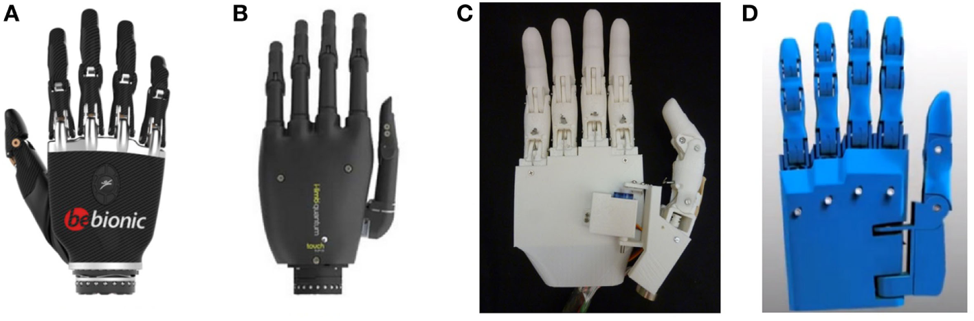
(From left to right) (A) Bebionic hand, (B) i-Limb hand, (C) Tact hand (Slade et al., 2015), and (D) Dextrus hand.
State of the Art Robotic Hand
Many researchers believe that the human hand is the perfectly engineered product of nature (Kalganova et al., 2015). They envision to build a robotic hand, which could function as close as possible to a human hand. Different from the prosthetic robotic hand, this robotic hand does not emphasize much about the weight, cost, and how it is linked to a human arm. The only aspect it focuses on is the simulation of the motion of a human hand to a robotic hand. The Stanford/JPL hand (1983) is one of the first dexterous hands to be invented (Salisbury and Roth, 1983). Most research work related to robotic hands has been conducted before 2010 by H. D. Bos.1
The Shadow Hand (Rothling et al., 2007) (Figure 2A) has 40 actuators and 20 DOFs. The UB hand IV (Melchiorri et al., 2013) (Figure 2B) is another example of a dexterous hand, which is closest to the human hand regarding functionality. Zhe Xu and his partners have made a low-cost modular, 20-DOF anthropomorphic robotic hand in 2013 (Xu et al., 2013) (Figure 2C), and a highly biomimetic robotic hand in 2016 (Xu and Todorov, 2016) (Figure 2D).
Figure 2
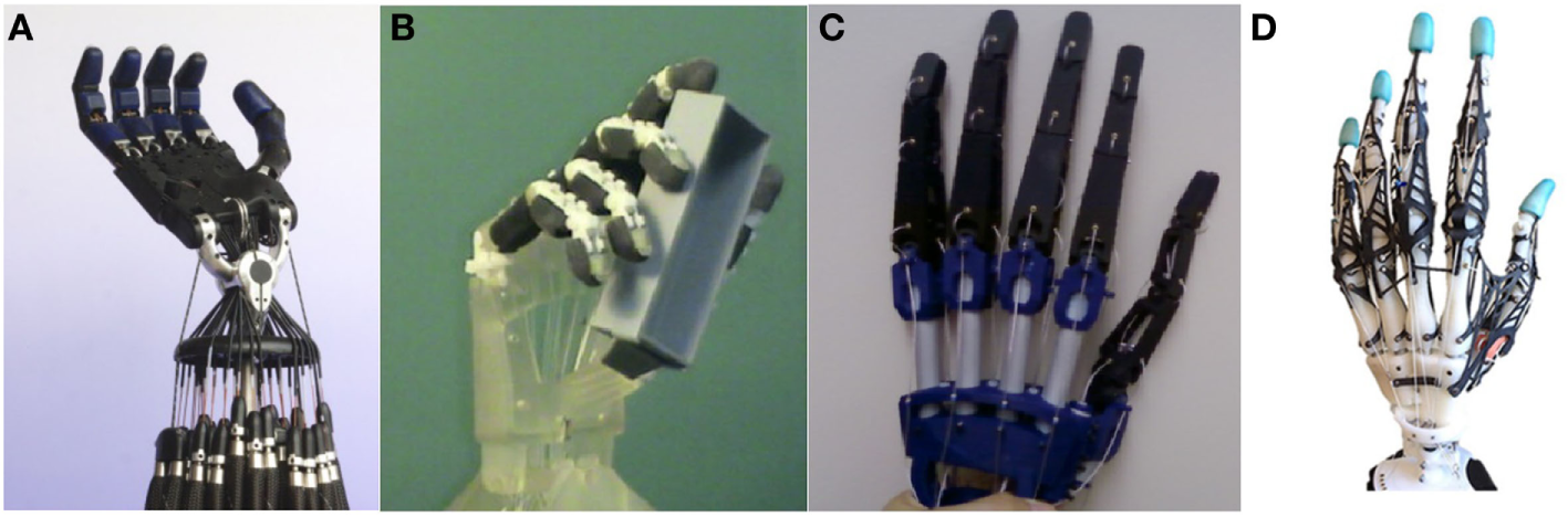
(From left to right) (A) Shadow hand (Rothling et al., 2007), (B) UB hand IV (Melchiorri et al., 2013), (C) Xu Zhe’s anthropomorphic robotic hand (Xu et al., 2013), and (D) Xu Zhe’s highly biomimetic robotic (Xu and Todorov, 2016).
Without the limitation of the number of actuators used, researchers can simulate more than 20 DOFs in a single robotic hand. Pneumatic control and electric motor control are two common solutions for the actuator of a robotic hand. Although the accuracy of the actuator improved drastically over the past decades, the size and weight of the actuator have not reduced significantly. Too many actuators will yield a big and heavy robotic hand control system. Therefore, this hinders the use of this form of robotic hand for most daily applications. “Underactuation” is a widely used concept in robotics (Birglen et al., 2007). It means having fewer actuators than the DOFs. Several robotic hands can have only one actuator. Researchers have used hardware lock way (Kontoudis et al., 2015), adaptive synergy (Catalano et al., 2014) to adjust the control of the robotic hand’s fingers. In contrast, they have more complex mechanical structure to alter the control of fingers. We will explain our design in chapter three.
Humanoid Robot’s Robotic Hand
Different humanoid robots are made based on a variety of application purposes. The Atlas robot (de Waard et al., 2013) (Figure 3A) from Boston Dynamics has been developed for outdoor search and rescue. Several diverse, powerful non-humanoid robotic hands can be linked to its arm one at a time for use in various scenarios. The ASIMO (Sakagami et al., 2002) (Figure 3B) by Honda Motor Co., Ltd. has a couple of dexterous humanoid hands, which can open the cover of a cup. Design details of these two state-of-the-art robots are still kept confidential. The i-Cub (Metta et al., 2008) (Figure 3C), which was developed by the RobotCub Consortium, has the learning ability to grasp objects. In our opinion, a possible drawback is that they look like a robot more than a human. The Inmoov (Langevin, 2014) robot’s most parts are 3D printable (Figure 3D), and its hand is one of the references to our robotic hand.
Figure 3
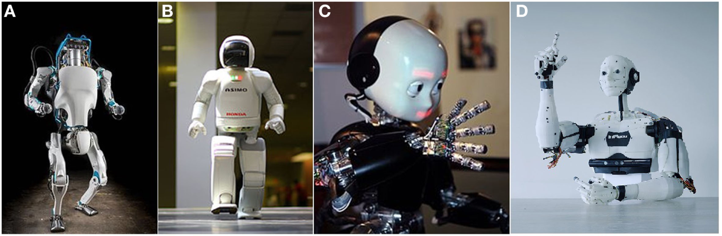
Humanoid robots (first row from left to right): (A) Atlas robot, (B) ASIMO robot, (C) i-Cub robot, and (D) InMoov Robot.
Conclusion on Robotic Hands and Design Goals
There is no robotic hand currently available that is suitable for the Nadine robot. We cannot adopt non-humanoid robotic hands for the Nadine robot as it needs a couple of humanoid robotic hands to match its physical appearance. Prosthetic robotic hands have a human-like model and robust performance. However, they are too big and heavy for the Nadine robot. Nonetheless, they showed us that fewer DOFs such as five or six could also handle many grasping jobs. The robotic hands for research purpose have superior grasping abilities, but their actuation control systems are too large and complex to be integrated into the Nadine robot.
So we need to design and make a new robotic hand for the Nadine robot, and our design goals are as follows. (1) The total weight of the robotic hand (with actuators) should be less than 300 g. From the previous test of the Nadine robot, an over-weighted robotic hand will significantly reduce her arm’s motion range. (2) The robotic hand should look like a real hand and have similar joints and motion range to mimic the human grasping gestures. (3) This robotic hand should be simple to make and easy to use.
Designs and Fabrication
In this section, we study the biomechanical features of a human hand such as the bones and joints in order to create robotic hand’s model. We apply the constraints of the human hand to simplify its motion model without significantly reducing its functionalities. Then, we design our new 3D hand model based on our understanding of hand motions.
Human Hand Features
A human hand has a total of 27 bones (Agur and Dalley, 2009). There are five bones in the palm, eight bones in the wrist, and 14 bones in five fingers (Figures 4A,B). The thumb consists of three joints named distal-interphalangeal (DIP) joint, interphalangeal joint, and trapeziometacarpal (TM) joint, whereas the other four fingers comprise three joints named DIP joint, proximal-interphalangeal (PIP) joint, and metacarpophalangeal (MCP) joint. Every normal human hand has 15 movable joints, which support the motions of the fingers.
Figure 4

Bones in human hand (A,B) (Agur and Dalley, 2009), hand’s degree of freedoms (DOF) (C) (Magnenat Thalmann et al., 2017), and mechanical model of our robotic hand (20 DOFs) (D) (Magnenat Thalmann et al., 2017).
In Figure 4C, we show a human hand with a total of 27 DOFs (Magnenat Thalmann et al., 2017). The thumb contributes five DOFs, and 16 DOFs are by four fingers. The remaining six DOFs from the wrist are called “global motion,” as they control the motion of the whole hand. All 21 DOFs from the fingers are called “local motion,” which controls the motion of the fingers.
Constraints of Human Hand
Lin et al. (
2000) give a formal representation of the constraints of human hands. There are three types of constraints:
- Type I.
Each finger has limited motion range due to the mechanical limitation of hand anatomy. For example, the motion range of the DIP joints is between 0 and 90°.
- Type II.
In each finger, DIP joint and PIP joint always move together.
- Type III.
People have a habit of making standard gestures. We usually bend all the fingers at the same time to make a fist, instead of one by one.
Simplification of the Hand Model
The five DOFs from the MCP joints, which represent fingers abduction and adduction motion, have a narrow motion range from −15 to 15° (Lin et al., 2000). The experiment from previous research on robotic hand shows that they are rarely involved in the grasping action (Xu and Todorov, 2016), so we have removed them from our robotic hand’s model. The four DOFs in the wrist come from the original mechanical design of the Nadine robot. The robotic arm will assist the robotic hand to make the global motion within the 3D working space. Figure 4D shows the mechanical model of it with a total of 20 DOFs.
3D Modeling and 3D Printing Technology
With the latest advancement in computer aided design (CAD) technology, people can create a robotic hand’s 3D model easily and quickly. The next issue to address would be how to fabricate a low-cost robotic hand within a short period. In traditional techniques of building a robot arm or a robotic hand, the parts are cut into specific shapes and linked together with glue or screws. However, with the rise of 3D printing technology (Berman, 2012), more and more robotic hands can be made using the 3D printer. 3D printing technology provides an easy way to make the conversion between 3D models to real objects using CAD software and a 3D printer. For example, we have used 3DS Max™ to make the 3D model of our robotic hand in polygons mesh. The 3D printer we utilized, uPrint™ SE Plus,2 can print out a hand-sized object within 20 h regardless of the complexity of the model. In the future, we plan to use the latest 3D printing technology to improve the quality of our robotic hand. The “Mark X Composite Printer”3 can use a new print material called carbon fiber to print. This material has some superior characteristics in comparison to aluminum. The Mark X print bed clicks into place with 10 μm accuracy.
For articulated robotic hands, the structure of the joints is one of the most critical designs that will affect the functionality. The finger joint of a good robotic hand should be able to act like a knuckle of a human hand. It not only links the two neighboring finger’s phalanges but also supports the motion of the fingers and grasping the power of the robotic hand. For commercial prosthetic hands, “linkage spanning” and “tendon linking” are two widely used joint coupling methods (Belter et al., 2013). “Linkage spanning” provides the best stability when moving the joint, while “tendon linking” gives more flexibility depending on the material used and the mechanical design. Each of the Inmoov robot’s finger, which is made from six separate parts, needs three pins and adhesive to link the parts together. In comparison, our robotic hand’s finger has adopted a new 3D model design inspired by non-assembly, articulated models (Cali et al., 2012). The new design of the joints integrates pin linkages to the fingers with an interlocking method. Figure 5A depicts the exploded view of its finger’s 3D model. The final product of the finger is shown below in blue (Figure 5B). This finger is ready to use right after the printing is completed with no additional assembly work required. The 3D model of InMoov robot’s finger is shown for comparison in Figure 5C.
Figure 5
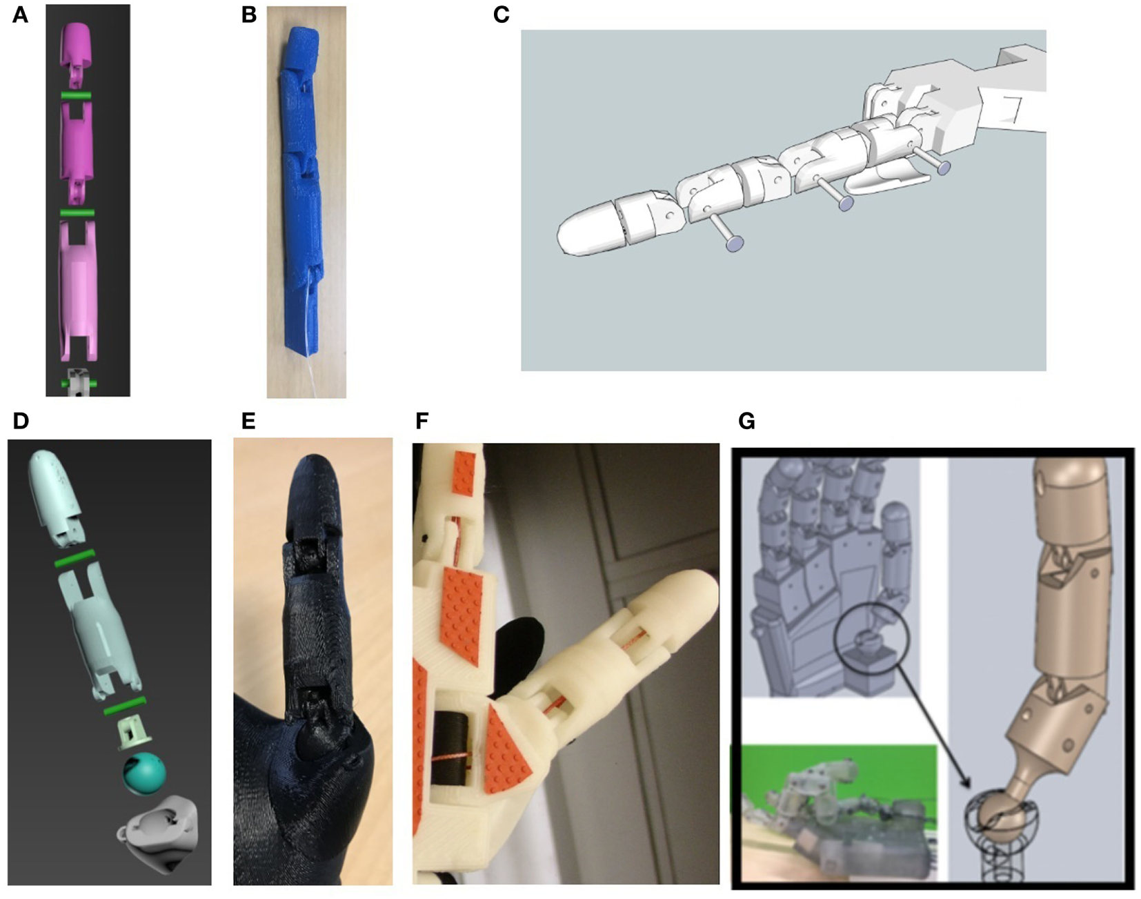
Our robotic hand finger’s 3D model (A), real finger (B), the Inmoov hand finger’s 3D model (C), our robotic hand thumb’s 3D model (D), real thumb (E), Inmoov hand thumb (F), and EthoHand’s thumb (G) (Konnaris et al., 2016).
This method can also be applied to the design of the thumb section. The thumb plays a more imperative role as compared to the other fingers in the grasping action. From our robotic hand’s DOF model, the thumb has two DOFs in the TM joint. In many other robotic hands’ 3D model, TM joint is split into two joints to represent two DOFs, for example, Inmoov hand (Figure 5F), Tact hand, and Dextrus hand. Nonetheless, this design will make the robotic hand, unlike a human hand. “Ball joints” are spherical bearings that allow a limited range of smooth movements in all directions. For robotic hands, “ball joints” can be used for simulating a joint with more than one DOF, such as a wrist’s joint or a thumb’s joint. EthoHand (Konnaris et al., 2016) has a ball-jointed thumb, which is controlled by three motors and six tendons (Figure 5G).
As part of the 3D model, our robotic hand integrates the “ball joint” mechanism to the robotic hand’s palm (Figures 5D,E). This design gives the TM joints of the robotic hand the ability to move in any direction. With the help of two cables, the thumb’s four motions, abduction/adduction, and flexion/extension can be simulated from this joint. This design improves the pinch function of the robotic hand.
These 3D printed based robotic hands greatly reduce the number of parts, time, and cost to make a copy. According to Inmoov’s website, more than 100 people have fabricated an Inmoov hand. Our robotic hand has an even more easy-to-make hand 3D model. Our robotic hand can be 3D printed in seven separate parts, including five fingers and two pieces of half palm. The seven parts can be linked together to function as a 15-joint robotic hand (Figure 6A). The posterior palm has a smooth shape, which is an improved design of the flexy hand (Burn et al., 2016), an open-sourced 3D modeled hand. After combining models of the seven parts together, it forms an entire piece of the robotic hand’s 3D model (Figure 6B). This combined 3D model can be 3D printed out as a whole (Figure 6C), thus saving assembly time and making mass production more straightforward.
Figure 6
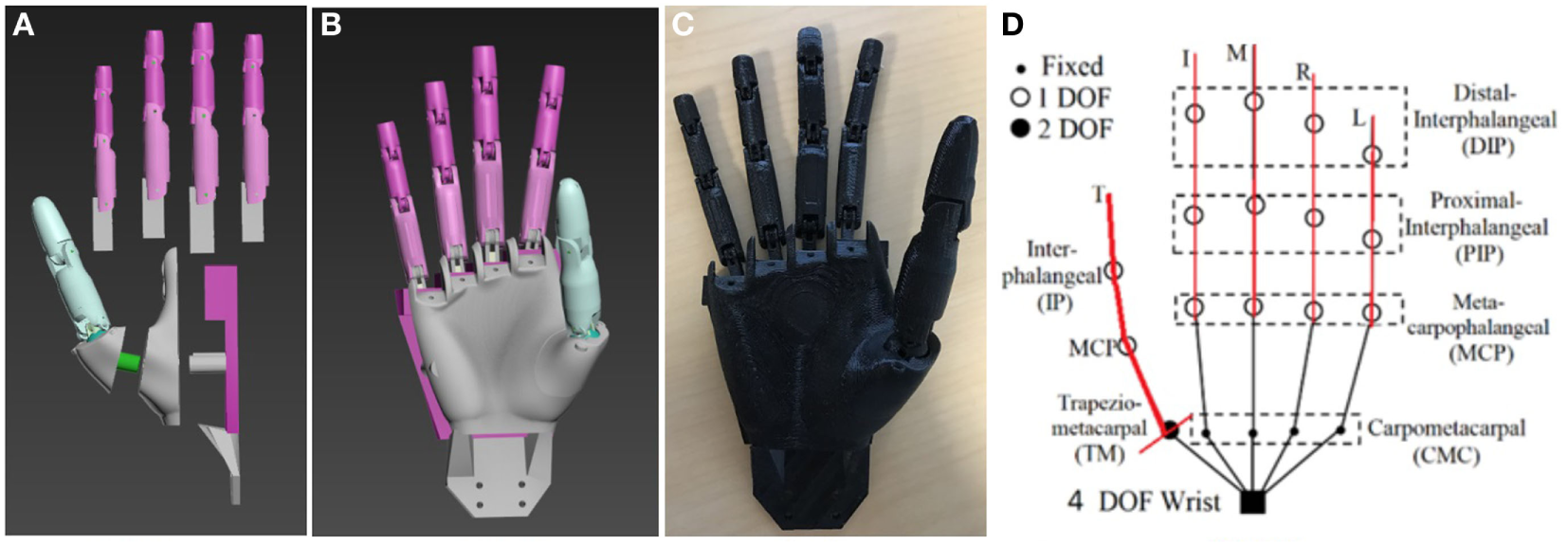
Our robotic hand’s 3D model (A,B), 3D printed out robotic hand (C), and actuated model of the robotic hand (D) [six degree of freedoms (DOFs)] (Magnenat Thalmann et al., 2017).
Finger Actuation
The simplest way to actuate the fingers is to use 16 actuators to control the 16 DOFs. Nevertheless, it will result in a heavy and complex control system. By applying the constraints of human hand Type II, we have used the cable-driven method to control it, which is similar to the Dextrus hand and the Inmoov hand. One cable actuates each finger, but the thumb has an additional cable for adduction motion (Figure 6D). Previous tests on those low DOFs robotic hands already show that six or seven DOFs are good enough for most grasping gestures (Slade et al., 2015; Konnaris et al., 2016).
Our robotic hand has six actuators to control 15 joints and six DOFs. Each finger of Nadine’s hand has three movable joints. A thread (0.5 mm diameter Nylon of 11 kg tensile strength) goes through the inner part of the whole finger to control the movement. When pulling the control thread, the finger will move starting from the DIP joint, which has the least resistance force of all finger joints. We set the motion range of the joints similar to a real hand’s by adjusting the length of the joint’s connector part. Table 1 shows our robotic hand (Robotic hand from IMI) joint moving angles as compared to the other robotic hands and human hand.
Table 1
| Robotic hand name | Metacarpo-phalangeal joints (Deg) | Proximal interphalan-geal joints (Deg) | Distal interphalan-geal joints (Deg) | Thumb flexion (Deg) | Thumb circumduc-tion (Deg) |
|---|---|---|---|---|---|
| Robotic hand from IMI (2017) | 0–90 | 0–110 | 0–90 | 0–90 | 0–90 |
| Tact (2015) (Slade et al., 2015) | 0–90 | 23–90 | 20 | 0–90 | 0–105 |
| Dextrus (2013) | 0–90 | 0–90 | 0–90 | 0–90 | 0–120 |
| i-Limb (2010) | 0–90 | 0–90 | 20 | 0–60 | 0–95 |
| Bebionic (2014) | 0–90 | 0–90 | 20 | – | 0–68 |
| Human hand (Lowe, 2006) | 90 | 100 | 90 | 70 | 70 |
Hand joint moving angle.
Motion Control System
For a cable-driven robotic hand, each finger is usually controlled by two cables and one motor. The motor uses a round or a two-arm horn to pull the two cables. The turning of the motor actuates the flexion/extension motion of the corresponding finger. Our robotic hand supports both two-cable and one-cable design. The one-cable design uses one cable to control each finger, which only actuates the flexion motion of the finger. Our robotic hand is 20% smaller than an adult human hand, thus allows the hand to be inserted into a normal-sized silicon artificial skin. The elasticity of the artificial skin will return the fingers to an extended position once the cables are relaxed. The one-cable design only requires one-arm horn of the motor which is smaller than a two-arm horn. Moreover, this design allows us to position the servo motors’ bed in steps, at the same time preventing any collision between servo motors. This results in a compact control system. The two-cable design takes up more space but enables the hand to function without artificial skin. It uses a Raspberry Pi II™ as the controller, sending pulse-width modulation signals to control the motion of each motor.
As the Nadine robot uses the pneumatic motor for its actuator and the torque force is not very strong, the weight of the new hand should be as light as possible to avoid exerting a heavy load onto the joint of the wrist. Our robotic hand weighs 150 g, which is much lighter than any of the existing hands. The three main reasons are (1) the 3D printed parts are not heavy due to the hollow design of the palm and fingers. It also saves printing materials and print time; (2) the servo motor used for the actuator of it (HITEC HS-5070MH) is only 12.7 g each; (3) it can be powered externally, doing away the need for a battery to be provisioned inside the hand. Table 2 shows the Nadine hand’s mass compared to other robotic hands.
Table 2
| Robotic hand name | Developer | Mass (g) |
|---|---|---|
| Nadine hand (2017) | NTU IMI | 150 |
| InMoov Hand (2015) | Gael Langevin | 400 |
| Tact (2015) | University of Illinois | 350 |
| Dextrus (2013) | Open Hand Project | 428 |
| Bebionic (2014) | RSL steeper | 550 |
| i-Limb (2010) | Touch Bionic | 460–465 |
| Zhe Xu hand (2016) | Zhe Xu et. al. | 942 |
Mass of the robotic hand.
Wrist Design and Servo Bed
We have two wrist designs for two robots. The robotic hand model originally has a four-hole wrist connector, which is designed to link to the wrist of Nadine robot (Figure 7B). A small servo bed for HITEC HS-5070MH has been fixed on the Nadine robot’s forearm (Figure 7C). The connector is interchangeable with another design to fit other robots. For Figure 7A, we have referenced the wrist part of Inmoov hand and made it as a part of our hand model. We also increased the size of the fingers to suit the new thin artificial hand skin. Then, we can test our robotic hand with Inmoov hand’s forearm and actuators.
Figure 7
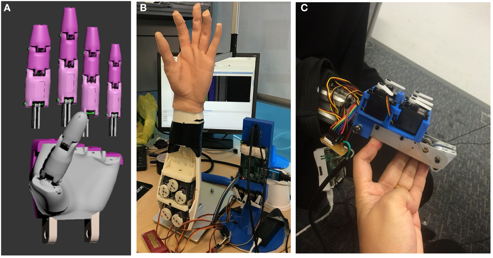
Bolt connector and thick finger 3D model (A) two test beds (B) and small test bed with Nadine robot’s forearm (C).
Silicon Artificial Skin
We purchased customize artificial hand skin from RenShan silicon rubber production company.4 The force needed to drive the finger is estimated based on the hardness and thickness of the silicon used to make the artificial skin. Based on our previous test experience, artificial skin, which is too thin (less than 2 mm) will be easily torn during the grasping tests. We tested the 5, 8, and 12° hardness silicon skin in 1.5, 3, and 5 mm conditions. We found HS-5070MH motor can only fully drive 5° hardness, 1.5 mm artificial skin, so, we have chosen this artificial skin for our later experiment.
Limitation of the Hardware
The grip strength of a male adult is generally up to 50 kg (Mathiowetz et al., 1985). It is much higher than the force that a small-sized servo motor can produce. We searched online for a small size and high torque actuator. The HITEC HS-5070MH has a dimension of 23.6 mm × 11.6 mm × 29 mm and provides a torque of 3.8 kg.cm when powered by 7.4 V. Although the grasp is contributed by five servo motors, significant torque is consumed by the cable-driven system. Thus, the grip strength is much lesser than a human hand. The heaviest object we tested is a small tin weight 200 g (Figure 8H). Our 3D print material (PLA) is also unable to withstand such high force and can easily break when its thickness is less than 1.5 mm. We tried to use a 1 mm dimension pin to link the joints of the finger, and we found it is easily to crack when the finger is driven by a 3.8 kg.cm torque servo motor. As the torque of servo motors continues to increase and the strength of 3D print materials improve constantly, these two related issues should be solved in early future. We neither calculated the efficiency of our system nor the tip force of each finger. They are not the main goal of our robotic hand. The evaluation of our robotic hand will be performed by direct grasping experiment.
Figure 8

Grasping experiment (power grasp).
Autonomous grasping requires precise motion control. For global motion control, it should move the robotic hand not only to a suitable grasping position but also in a correct orientation. For local motion, it should move each finger to form the planned grasping gestures in the correct sequence. However, due to the mechanical design and the tolerance of the actuators, which manage the Nadine robot’s arm and hand, we are unable to precisely control the grasp path of fingers. However, as compliant fingers design, this hand is still able to create all the important grasp gestures in the experiments. We are still working on the precise control with the cable-driven method.
The surface of 3D printed robotic hand is solid and smooth; it is hard to create enough friction when holding a heavy object. To solve this issue, we have added Blu Tack to the contact points so as to increase the coefficient of friction and improve the grasping force. Blu Tack is a reusable putty-like pressure-sensitive adhesive produced by Bostik, commonly used to attach lightweight objects (such as posters or sheets of paper) to walls or other dry surfaces. The Blu Tack is removed in the later experiments with the artificial skin.
Experiments
To evaluate the overall performance of our robotic hand, we have conducted grasping experiments using different objects from everyday life. After that, we test the robotic hand with and without the artificial skin. Last but not least, the grasping experiments were tested on the Nadine robot using the new robotic hand.
Grasping Experiment Based on Cutkosky’s Taxonomy
In Cutkosky’s human hand taxonomy (Cutkosky, 1989), there are 16 grasping types, which have different gestures. He divided the grasp into two major categories, power and precision. The “power grasp” emphasizes on security and stability whereas the “precision grasp” emphasizes on dexterity and sensitivity. These two categories have several subcategories based on the geometry of the target. For all grasping tests, we placed the target objects at a fixed position in front of our robotic hand, and then we sent a command to control each finger to approach the target object. A few gestures were generated only after multiple trials.
For “power grasp,” it is divided into prehensile and non-prehensile based on whether clamping is required. Non-prehensile grasping is usually used for objects bigger than the hand. Due to the mechanical limitation of our robotic hand, its thumb is unable to move to the palm’s plane. Therefore, we have used a palm and four fingers as the platform to support the target (Figure 8A).When the target must be clamped, prehensile grasping is chosen in which the fingers and palm confine the object. The basic geometric considerations of the objects are critical. If the object is thin, we use Lateral Pinch as shown in Figure 8B. In Figures 8C,D, fingers surround the object in radial symmetry when the object is compact like a CD or a ball. For a long object, fingers surround the object in wrap symmetry, as depicted in Figures 8E–I.
“Precision grasp” has two subcategories based on the target’s geometry. For a compact object, fingers support the object in the shape of a disk and a sphere, as shown in Figures 9A–C. For a long object, the thumb opposes one or several fingers (Figures 9D–G).
Figure 9
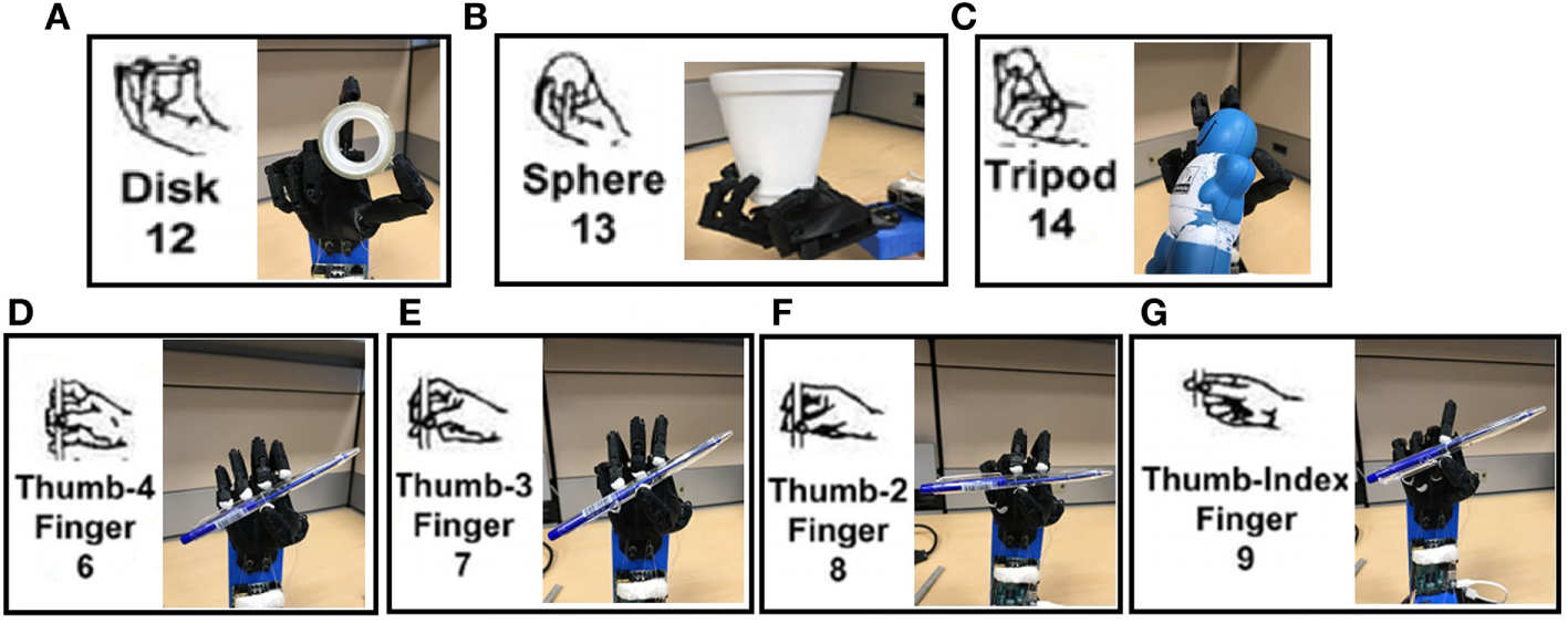
Grasping experiment (precision grasp).
Grasping analysis is dependent on several parameters such as finger force, gesture, and friction between the hand and the target object, making it difficult and complex. In these experiments, we focus on some important features of the robotic hand. In conclusion, for power grasp, our robotic hand can hold an object as heavy as 300 g and lift it up with a stable grip. Heavier objects will prevent the grasping gesture as the driven force is insufficient. That means the grasp fails and the object could slip out. For precision grasp, it can hold different objects with suitable gestures based on their shapes. We are testing our robotic hand with more grasp gestures (Feix et al., 2009b; Deimel and Brock, 2016).
Grasp Experiments with Artificial Silicon Skin
We test our robotic hand with an artificial silicon skin. The skin will limit the driven force and hence might reduce the motion range of the fingers. However, compared to the first experiment, it will make the robotic hand fit to Nadine robot and achieve a human-like grasp. We tested four different shape objects with two common grasp gestures. In the experiments, we pinched a card and a spoon. We also held a stapler and a slim cylinder. Similar to the first experiment, we manually placed the objects in front of our robotic hand and controlled the fingers to grasp (Figure 10). We are still working with our vendor for a softer and more human-like artificial skin.
Figure 10
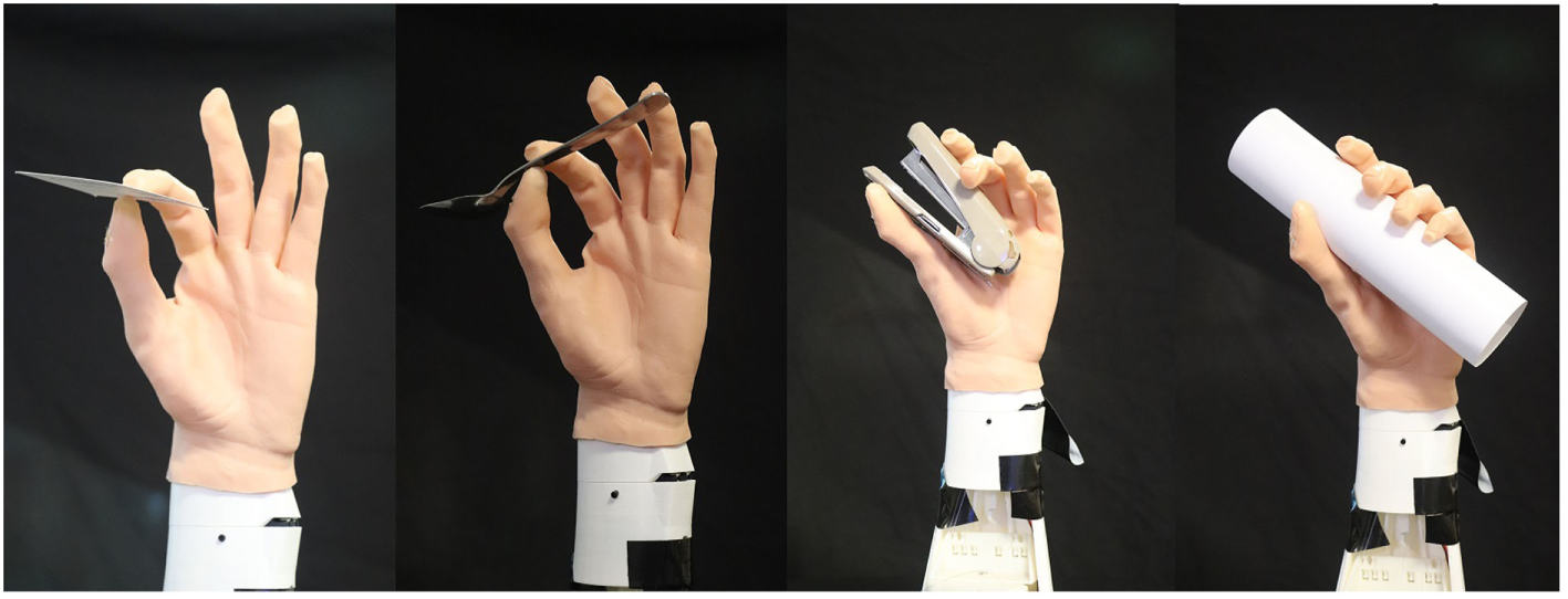
Grasping experiment with artificial skin.
We have tested our robotic hand on the Nadine robot. The test target is a small-sized toy. We used the plotted motions from the virtual Nadine in Section “Grasp Experiments with artificial silicon skin” and applied to the Nadine robot controller. The results show that the Nadine robot can grasp the object as per the plotted motions. Figure 11 provides four screenshots of the Nadine robot grasp test.
Figure 11
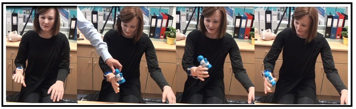
Four intermediate actions of the virtual Nadine and four screenshots of the Nadine robot grasp test (Magnenat Thalmann et al., 2017).
Conclusion and Future Work
We have described the modeling and fabrication of a new 3D printable robotic hand for the humanoid robot. We studied how a human hand functions at first, and then tried to replicate the important features on our robotic hand. The robotic hand has a simple and practical design, which successfully simulated most human hand gestures in our grasp experiment. The robotic hand weighs 150 g. The test shows that it can handle most of the important grasping configurations. This robotic hand can greatly improve the overall performance of humanoid robots.
In future, we plan to improve it in several ways:
Increasing the grasping force and reducing the motion errors;
Integrating visual recognition to its control system to achieve autonomous grasping of objects based on the visual information;
Improving the grasping manner of the Nadine robot and make it more natural human-like.
Statements
Author contributions
NT has initiated the research on Nadine’s robot hand as she is the Principal Investigator of Nadine social robot research. LT has designed and implemented Nadine’s robot hardware hand and done state of the art. All authors have discussed the research every week and have contributed to the writing and editing of the paper.
Funding
This research is supported by the BeingTogether Centre, a collaboration between Nanyang Technological University (NTU) Singapore and University of North Carolina (UNC) at Chapel Hill. The BeingTogether Centre is supported by the National Research Foundation, Prime Minister’s Office, Singapore under its International Research Centres in Singapore Funding Initiative.
Conflict of interest
The authors declare that the research was conducted in the absence of any commercial or financial relationships that could be construed as a potential conflict of interest.
Supplementary material
The Supplementary Material for this article can be found online at http://www.frontiersin.org/article/10.3389/frobt.2017.00065/full#supplementary-material.
Footnotes
1.^ Evolution of Robot Hands Author: H.D. Bos Supervisor: ir. M. Wassink: https://www.ram.ewi.utwente.nl/aigaion/attachments/single/363.
2.^ uPrint SE Plus: http://www.stratasys.com/3d-printers/idea-series/uprint-se-plus.
3.^ 3D printer mark X: http://www.chemtron.com.sg/3d-printers/mark-x-composite-printer.
References
1
Agur A. M. Dalley A. F. (2009). Grant’s Atlas of Anatomy. Lippincott Williams & Wilkins.
2
Belter J. T. Segil J. L. Dollar A. M. Weir R. F. (2013). Mechanical design and performance specifications of anthropomorphic prosthetic hands: a review. J. Rehabil. Res. Dev.50, 599–617.10.1682/Jrrd.2011.10.0188
3
Berman B. (2012). 3D printing: the new industrial revolution. Bus. Horiz.55, 155–162.10.1016/j.bushor.2011.11.003
4
Birglen L. Laliberté T. Gosselin C. M. (2007). Underactuated Robotic Hands, Vol. 40. Springer.
5
Burn M. B. Ta A. Gogola G. R. (2016). Three-dimensional printing of prosthetic hands for children. J. Hand Surg. Am.41, e103–e109.10.1016/j.jhsa.2016.02.008
6
Cali J. Calian D. A. Amati C. Kleinberger R. Steed A. Kautz J. et al (2012). 3D-printing of non-assembly, articulated models. ACM Trans. Graph.31:130.10.1145/2366145.2366149
7
Catalano M. G. Grioli G. Farnioli E. Serio A. Piazza C. Bicchi A. (2014). Adaptive synergies for the design and control of the Pisa/IIT SoftHand. Int. J. Robot. Res.33, 768–782.10.1177/0278364913518998
8
Cummings D. (1996). Prosthetics in the developing world: a review of the literature. Prosthet. Orthot. Int.20, 51–60.10.3109/03093649609164416
9
Cutkosky M. R. (1989). On grasp choice, grasp models, and the design of hands for manufacturing tasks. IEEE Trans. Robot. Autom.5, 269–279.10.1109/70.34763
10
de Waard M. Inja M. Visser A. (2013). Analysis of flat terrain for the atlas robot. Paper Presented at the AI & Robotics and 5th RoboCup Iran Open International Symposium (RIOS), 2013 3rd Joint Conference of.10.1109/RIOS.2013.6595324
11
Deimel R. Brock O. (2016). A novel type of compliant and underactuated robotic hand for dexterous grasping. Int. J. Robot. Res.35, 161–185.10.1177/0278364915592961
12
Feix T. Pawlik R. Schmiedmayer H.-B. Romero J. Kragic D. (2009a). A comprehensive grasp taxonomy. Paper Presented at the Robotics, Science and Systems: Workshop on Understanding the Human Hand for Advancing Robotic Manipulation. Available at: www.csc.kth.se/grasp/taxonomyGRASP.pdf
13
Feix T. Pawlik R. Schmiedmayer H.-B. Romero J. Kragic D. (2009b). A comprehensive grasp taxonomy. Paper Presented at the Robotics, Science and Systems: Workshop on Understanding the Human Hand for Advancing Robotic Manipulation. Available at: www.csc.kth.se/grasp/taxonomyGRASP.pdf
14
Hirukawa H. (2005). Session overview humanoids. Paper Presented at the ISRR.10.1007/978-3-540-48113-3_9
15
Kalganova T. Akyürek E. Mukhtar M. Steele L. Simko M. Nimmo A. et al (2015). A Novel Design Process of Low Cost 3D Printed Ambidextrous Finger Designed for an Ambidextrous Robotic Hand, 14:475–488.
16
Konnaris C. Gavriel C. Thomik A. A. C. Faisal A. A. (2016). “EthoHand: a dexterous robotic hand with ball-joint thumb enables complex in-hand object manipulation,” in 2016 6th IEEE International Conference on Biomedical Robotics and Biomechatronics (BioRob), 1154–1159.10.1109/BIOROB.2016.7523787
17
Kontoudis G. P. Liarokapis M. V. Zisimatos A. G. Mavrogiannis C. I. Kyriakopoulos K. J. (2015). Open-source, anthropomorphic, underactuated robot hands with a selectively lockable differential mechanism: towards affordable prostheses. Paper Presented at the Intelligent Robots and Systems (IROS), 2015 IEEE/RSJ International Conference on, 5857–5862.10.1109/IROS.2015.7354209
18
Langevin G. (2014). InMoov-Open Source 3D Printed Life-Size Robot. Available at: http://inmoov.fr/
19
Lin J. Wu Y. Huang T. S. (2000). “Modeling the constraints of human hand motion,” in Workshop on Human Motion, Proceedings (Los Alamitos, CA: IEEE), 121–126.
20
Lowe W. (2006). Orthopedic Assessment in Massage Therapy. Daviau Scott.
21
Magnenat Thalmann N. Tian L. Yao F. (2017). “Nadine: a social robot that can localize objects and grasp them in a human way,” in Front. Electron. Vol. 433, Technol. Lecture Notes in Electrical Engineering, (eds) PrabaharanS.ThalmannN.Kanchana BhaaskaranV. (Singapore: Springer) 1–23.10.1007/978-981-10-4235-5_1
22
Malbran M. D. (2011). World report on disability. J. Policy Pract. Intell. Disabil.8, 290–290.10.1111/j.1741-1130.2011.00320.x
23
Mathiowetz V. Kashman N. Volland G. Weber K. Dowe M. Rogers S. (1985). Grip and pinch strength: normative data for adults. Arch. Phys. Med. Rehabil.66, 69–74.
24
Medynski C. Rattray B. (2011). Bebionic Prosthetic Design. Proceedings of the MEC’11 Conference. UNB.
25
Melchiorri C. Palli G. Berselli G. Vassura G. (2013). Development of the UB hand IV: overview of design solutions and enabling technologies. IEEE Robot. Autom. Mag.20, 72–81.10.1109/MRA.2012.2225471
26
Metta G. Sandini G. Vernon D. Natale L. Nori F. (2008). The iCub humanoid robot: an open platform for research in embodied cognition. Paper Presented at the Proceedings of the 8th Workshop on Performance Metrics for Intelligent Systems (New York, NY: ACM), 50–56.
27
Mori M. (1970). The uncanny valley. Energy7, 33–35.
28
Needham J. (1974). Science and Civilisation in China: Historical Survey, from Cinnabar Elixirs to Synthetic Insulin, Vol. 2. Cambridge University Press.
29
Percy R. Timbs J. (1840). The Mirror of Literature, Amusement, and Instruction, Vol. 35. London: J. Limbird.
30
Phillips B. Zingalis G. Ritter S. Mehta K. (2015). A review of current upper-limb prostheses for resource constrained settings. Paper Presented at the Global Humanitarian Technology Conference (GHTC) (Seattle, WA: IEEE), 52–58.
31
Riskin J. (2016). The Restless Clock: A History of the Centuries-Long Argument Over What Makes Living Things Tick. University of Chicago Press.
32
Rosheim M. E. (1994). Robot Evolution: The Development of Anthrobotics. John Wiley & Sons.
33
Rothling F. Haschke R. Steil J. J. Ritter H. (2007). Platform portable anthropomorphic grasping with the bielefeld 20-dof shadow and 9-dof tum hand. Paper Presented at the Intelligent Robots and Systems, 2007. IROS 2007. IEEE/RSJ International Conference on, 2951–2956.10.1109/IROS.2007.4398963
34
Sakagami Y. Watanabe R. Aoyama C. Matsunaga S. Higaki N. Fujimura K. (2002). The intelligent ASIMO: system overview and integration. Paper Presented at the Intelligent Robots and Systems, 2002. IEEE/RSJ International Conference on, 2478–2483.10.1109/IRDS.2002.1041641
35
Salisbury J. K. Roth B. (1983). Kinematic and force analysis of articulated mechanical hands. J. Mech. Transm. Autom. Des.105, 35–41.10.1115/1.3267342
36
Siciliano B. Khatib O. (eds). (2016). Springer Handbook of Robotics. Springer.10.1007/978-3-540-30301-5
37
Slade P. Akhtar A. Nguyen M. Bretl T. (2015). “Tact: design and performance of an open-source, affordable, myoelectric prosthetic hand,” in 2015 IEEE International Conference on Robotics and Automation (ICRA), 6451–6456.10.1109/ICRA.2015.7140105
38
Tavakoli M. Sayuk A. Lourenço J. Neto P. (2017). Anthropomorphic finger for grasping applications: 3D printed endoskeleton in a soft skin. Int. J. Adv. Manuf. Technol.91, 2607–2620.10.1007/s00170-016-9971-8
39
ten Kate J. Smit G. Breedveld P. (2017). 3D-printed upper limb prostheses: a review. Disabil. Rehabil. Assist. Technol.12, 300–314.10.1080/17483107.2016.1253117
40
Woledge R. (1998). Possible effects of fatigue on muscle efficiency. Acta Physiol.162, 267–273.10.1046/j.1365-201X.1998.0294e.x
41
Xu Z. Kumar V. Todorov E. (2013). A low-cost and modular, 20-DOF anthropomorphic robotic hand: design, actuation and modeling. Paper Presented at the Humanoid Robots (Humanoids), 2013 13th IEEE-RAS International Conference on, 368–375.10.1109/HUMANOIDS.2013.7030001
42
Xu Z. Todorov E. (2016). “Design of a highly biomimetic anthropomorphic robotic hand towards artificial limb regeneration,” in 2016 IEEE International Conference on Robotics and Automation (ICRA), 3485–3492.10.1109/ICRA.2016.7487528
Summary
Keywords
robotic hand, modeling, 3D printing, cable-driven system, grasp planning
Citation
Tian L, Magnenat Thalmann N, Thalmann D and Zheng J (2017) The Making of a 3D-Printed, Cable-Driven, Single-Model, Lightweight Humanoid Robotic Hand. Front. Robot. AI 4:65. doi: 10.3389/frobt.2017.00065
Received
18 May 2017
Accepted
21 November 2017
Published
04 December 2017
Volume
4 - 2017
Edited by
Jörn Malzahn, Fondazione Istituto Italiano di Technologia, Italy
Reviewed by
Kensuke Harada, Osaka University, Japan; Vincent Wall, Technische Universität Berlin, Germany
Updates
Copyright
© 2017 Tian, Magnenat Thalmann, Thalmann and Zheng.
This is an open-access article distributed under the terms of the Creative Commons Attribution License (CC BY). The use, distribution or reproduction in other forums is permitted, provided the original author(s) or licensor are credited and that the original publication in this journal is cited, in accordance with accepted academic practice. No use, distribution or reproduction is permitted which does not comply with these terms.
*Correspondence: Nadia Magnenat Thalmann, nadiathalmann@ntu.edu.sg
Specialty section: This article was submitted to Humanoid Robotics, a section of the journal Frontiers in Robotics and AI
Disclaimer
All claims expressed in this article are solely those of the authors and do not necessarily represent those of their affiliated organizations, or those of the publisher, the editors and the reviewers. Any product that may be evaluated in this article or claim that may be made by its manufacturer is not guaranteed or endorsed by the publisher.