 Jekaterina Maksimcuka1
 Akiko Obata2*William W. Sampson1
 Remi Blanc3
 Chunxia Gao2
 Philip J. Withers1,4,5Olga Tsigkou1
 Toshihiro Kasuga2
 Peter D. Lee1,5
 Gowsihan Poologasundarampillai1,5*
- 1School of Materials, University of Manchester, Manchester, United Kingdom
- 2Division of Advanced Ceramics, Nagoya Institute of Technology, Nagoya, Japan
- 3Thermo Fisher Scientific, Bordeaux, France
- 4Manchester X-ray Imaging Facility, University of Manchester, Manchester, United Kingdom
- 5Research Complex at Harwell, Rutherford Appleton Laboratory, Harwell, United Kingdom
Electrospinning allows the production of fibrous networks for tissue engineering, drug delivery, and wound healing in health care. It enables the production of constructs with large surface area and a fibrous morphology that closely resembles the extracellular matrix of many tissues. A fibrous structure not only promotes cell attachment and tissue formation but could also lead to very interesting mechanical properties. Poly(3-hydroxybutyrate-co-4-hydroxybutyrate) (P(3HB-co-4HB)) is a biodegradable polyester that exhibits a large (>400%) elongation before failure. In this study, synchrotron X-ray phase contrast imaging was performed during tensile deformation to failure on a non-woven fiber mat of P(3HB-co-4HB) fibers. Significant reorientation of the fibers in the straining direction was observed, followed by localized necking and eventual failure. From an original average fiber diameter of 4.3 µm, a bimodal distribution of fiber diameter (modal diameters of 1.9 and 3.7 µm) formed after tensile deformation. Extensive localized necking (thinning) of fibers between (thicker) fiber–fiber contacts was found to be the cause for non-uniform thinning of the fibers, a phenomenon that is expected but has not been observed in 3D previously. The data presented here have implications not only in tissue regeneration but for fibrous materials in general.
Introduction
Electrospun constructs for the repair of load-bearing tissues are required to have adequate mechanical properties. However, the failure mechanisms of electrospun fibrous materials are not well understood. Existing literature focuses on failure modes of individual fibers and/or on bulk mechanical properties of whole fiber mats. In this manuscript, we investigate the tensile deformation of a biodegradable polyester, P(3HB-co-4HB), that undergoes large elongation to failure using a bespoke tensile tester (P2R) and synchrotron X-ray tomography to shed light on structure–property relationships.
Biodegradable and biocompatible polymers are in use to produce implant materials for tissue regeneration. Polyesters such as poly(l-lactic acid) (PLLA) and poly(l-glycolic acid) (PLGA) are used in several FDA-approved medical devices (Jamshidian et al., 2010; Makadia and Siegel, 2011). Poly(3-hydroxybutyrate-co-4-hydroxybutyrate) (P(3HB-co-4HB)) is a type of polyester in the family of polyhydroxyalkanoates (PHA) and is produced by microorganisms under unbalanced growth conditions (Türesin et al., 2001). PHAs are of significant interest to the biomedical community due to their biodegradability, biocompatibility, and mechanical properties (Anjum et al., 2016; Li and Loh, 2017). Physical properties of microbial polyesters can be regulated by varying the proportions of the copolymers. In the case of P(3HB-co-4HB), enzymatic degradation and mechanical properties, such as elongation and tensile strength, can be regulated by varying the 4HB content. One of the remarkable properties of P(3HB-co-4HB) is its large elongation before failure. Saito and Doi (1994) showed that the P(3HB-co-4HB) films with 82 mol% 4HB exhibit 1320% elongation before failure. These remarkable mechanical properties of P(3HB-co-4HB) are a result of a unique 4HB fraction that reduces the crystallinity of the polymer which in turn influences the mechanical properties (Saito and Doi, 1994; Türesin et al., 2001). Thus, P(3HB-co-4HB) has considerable potential for use as a biodegradable material in implants requiring large elongation.
Electrospun fibers of biodegradable polymers are excellent candidate materials for use in tissue engineering, drug delivery, and wound healing (Greiner and Wendorff, 2007; Sill and von Recum, 2008; Poologasundarampillai et al., 2011; Vigneswari et al., 2016). Electrospinning is a versatile technique to produce fibrous materials with structures ranging from randomly oriented fiber mats and aligned fiber conduits to spun knitted or twisted yarns (Teo and Ramakrishna, 2006) or cotton-wool-like structures (Poologasundarampillai et al., 2014). Continuous fibers with diameters ranging from 10s of nanometers to a few microns can be produced (Badami et al., 2006; Jose et al., 2009). The continuous ultrathin fibers have unique properties when compared to bulk materials. Interesting observations of higher elastic modulus and tensile strength compared to bulk films have been observed, although with controversy on the specific fiber diameter at which the increase starts to occur (Tan and Lim, 2004; Liu et al., 2011). Several types of electrospun P(3HB-co-4HB) fibres have been developed for use in tissue regeneration applications. Vigneswari et al. (2016) prepared electrospun P(3HB-co-4HB)/collagen peptides for wound healing and reported that cell compatibility (in vitro) and wound healing (in vivo) were improved by adding collagen peptides to P(3HB-co-4HB). Zhijiang et al. (2017) controlled mechanical properties of electrospun P(3HB-co-4HB) by blending zein, natural protein obtained from corn, and confirmed the electrospun P(3HB-co-4HB)/zein was biocompatibile in vitro. Nishizuka et al. (2014) focused on the excellent elongation property of P(3HB-co-4HB) to develop a novel fracture fixation device, intramedullary-fixation with biodegradable materials, for weakened long bones using electrospun P(3HB-co-4HB) as a bone-cement bag. All the aforementioned and future developments of electrospun P(3HB-co-4HB) materials for tissue regeneration heavily depends on an in-depth knowledge of their mechanical behavior under tensile loading and their failure modes. In this study, X-ray tomography was employed to investigate the mechanical deformation of electrospun P(3HB-co-4HB) networks over large tensile strains, and the correlation of mechanical properties to structure is investigated.
Tensile properties of electrospun fiber mats depend on several factors: the microstructure of individual fibers and macroscopic organization of the fibers, including alignment, their length, porosity, the number of fiber-fiber contacts, and the joint strength at these regions of contact (Pedicini and Farris, 2003; Rizvi et al., 2012). Further, many of the techniques for conventionally studying the micromechanics of materials are not well suited to the study of 3D fiber mats, and so their behavior is not yet well understood. Such electrospun materials have submicron features which are not easily resolved using optical techniques. Fiber mats up to 1 mm in thickness are often produced for use as membranes in tissue engineering, EM, and optical measurements which have short depth of focus are not able to capture, simultaneously, the deformation of the entire 3D fiber mats. Despite these limitations, these techniques have been successfully applied to assess the deformation of single fibers and their mechanical properties. Several authors have employed SEM in combination with AFM or optical microscopy in combination with AFM- or MEMS-based device to investigate the structure of nanofibers following tensile deformation (Yu et al., 2000; Zussman et al., 2006; Naraghi et al., 2007; Baker et al., 2016). Such investigations have revealed that the deformation of electrospun fibers is via multiple neck formation (also described as ripples) and crazing followed by rupture of multiple thin fibrils. Literature on the failure mechanisms of whole fiber mats is sparse. It is known that in the case of non-woven fiber mats the fibers first reorientate to the direction of the applied force, and this is then followed by fiber thinning and failure of individual fibers and hence the network (Lee et al., 2002; Pedicini and Farris, 2003; Kim et al., 2004; Lu et al., 2008; Cheng et al., 2011). The complex micro and macro-structures formed by electrospinning makes it a difficult task to explain failure mechanisms of entire fiber mats and then to compare it to individual fibers and bulk materials. Bulk elastomeric materials fail at high strains; molecular realignment at lower stresses leads to accommodation of large elongation and concurrent strain hardening, bulk materials therefore fracture at higher stresses and large strain (Pedicini and Farris, 2003). While, electrospun materials fail at considerably lower strains compared to their bulk counterparts. Attempts have been made in the past to explain these disparities in the failure of electrospun fiber mats to bulk materials through their differences in molecular alignments and fiber mat structure (Pedicini and Farris, 2003). Although these insights are useful, the structural correlation to deformation are derived from ex situ tensile testing and post-SEM imaging, where the fibers were allowed to relax between loads, leading to an incomplete picture of the failure mechanism. Mathematical models of random fiber mats on the other hand have come a long way in describing the micro and macro structural changes with tensile testing (Xiaofan et al., 2009; Rizvi et al., 2012; Rizvi and Pal, 2014; Mohammadzadehmoghadam et al., 2016; Zundel et al., 2017). In particular, elastic moduli, tensile strength, fiber realignment, and fiber elongation (stretch) with network connectivity can be modeled with good accuracy. However, models assume a homogeneous intra-fiber structure and hence are unable to reproduce changes in fiber diameter with strain. The assumptions of idealized inter–fiber interactions and network characteristics also produce an idealistic prediction of the structural changes.
In this study, we perform in situ 3D high resolution X-ray computed tomography (CT) measurements on tensile testing of P(3HB-co-4HB) fiber mats using synchrotron based X-rays available at the Diamond Light Source Diamond-Manchester (I13-2) beamline. We then apply sophisticated segmentation and quantification of the data to provide novel insights into the failure of P(3HB-co-4HB) non-woven fiber mats.
Materials and Methods
Preparation of P(3HB-co-4HB) Fiber Mats
Poly(3-hydroxybutyrate-co-4-hydroxybutyrate), G5, Japan) with a molecular weight of 660 kDa and containing 18 mol% 4-hydroxybutyrate (4HB) was dissolved in a mixture of chloroform and acetone (Wako Pure Chemicals Industries Ltd., Japan) with 100/0, 75/25, 65/35, 50/50, and 0/100 of the chroloform/acetone weight ratio and P(3HB-co-4HB) concentration of 8 wt%. P(3HB-co-4HB) fiber mats were fabricated with a Nanofibre Electrospinning Unit (Kato Tech Co., Japan) run at 8 kV applied to a metallic needle placed 150 mm from a grounded rotating drum collector rotating at a speed of 0.08 m s−1 (Figure 1). A solution flow rate of 1.5 µl s−1 was used.
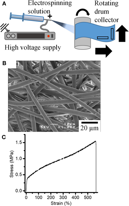
Figure 1. (A) Schematic of electrospinning setup used to produce fiber mats. (B) SEM image of the fiber mats obtained. (C) Typical stress–strain curves for the tensile deformation of the fiber mats.
Microstructural Characterization
The surface morphology and fiber diameter of the fiber mats were analyzed by scanning electron microscopy (JSM-6301F, JEOL, Japan). Prior to the SEM observation, all of the samples were coated with amorphous osmium (Neoc, Meiwafosis, Japan). The average fiber diameter was determined from 100 measurements using ImageJ software.
Tensile Tests
Rectangular P(3HB-co-4HB) fiber mats (n = 8) measuring 20 mm length, 5 mm width, and 0.1 mm thickness were cut from as-prepared samples with the longest side (20 mm) in the direction parallel or perpendicular to the spinning direction, as shown in Figure 1. Sample cross sectional area was calculated as 5 mm × 0.1 mm. Cut samples were then tested in tension along this side using Autograph (AGS-G, Shimadzu, Japan) at a rate of 0.1 mm s−1.
In Situ Synchrotron Imaging and Tensile Deformation
Tensile Testing on the P2R
Dog bone shaped fiber mats (Figure 2) were laser cut using an FB series laser cutter with a power of 5 W and 100 mm s−1 travel speed. Samples were clamped between a set of purpose-built grips and loaded onto a bespoke micro-mechanical tester (P2R) (Puncreobutr et al., 2012). Tensile deformation was performed at a rate of 0.1 mm s−1 until failure.
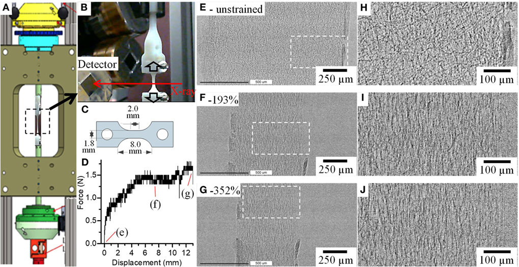
Figure 2. (A) P2R tensile tester with (B) fiber mat held together between bespoke grips on the Diamond Manchester Beamline (I13-2) at Diamond Light Source. (C) Dog-bone-shaped samples used for the tests and (D) a force vs displacement curve obtained for the P(3HB-co-4HB) fiber mat. (E–J) show radiographs and magnified images of boxed areas on (E–G), respectively, of the fiber mats before (e-unstrained), after 7 mm (f-193%) and 13 mm (g-352%) displacements.
Synchrotron Imaging
Radiographic imaging and CT were performed with tensile deformation of the P(3HB-co-4HB) fiber mats at the Diamond Manchester Branchline (I13-2) (Rau et al., 2011) Diamond Light Source. Polychromatic X-rays with energy in the range of 8–35 kV filtered with C, Al, and stainless steel were used. Radiographs of the deformation and failure of the fiber mats were captured at a rate of 67 Hz using a PCO edge camera with 2,560 × 2,160 detector array giving an effective pixel size of 0.81 µm. Radiographs centered in the middle of the dog bone sample was obtained. As the sample was strained at 0.1 mm s−1, the testing rig was lowered at half the strain rate to keep the same region of fiber mat in view.
Due to the X-ray induced damage on the samples, tomography was performed post-tensile deformation to various strains on different samples. 1,500 projections were collected from 0 to 180° with a step size of 0.12° and exposure ranging from 0.075 to 0.15 ms from the center of the dog-bone sample where maximum strain is expected. Filtered back projection was applied to reconstruct the projections using codes developed at Diamond Light Source (Atwood et al., 2015). The resulting tomographs each comprise 2,560 × 2,560 × 2,160 voxels with an effective voxel size of 0.33 µm.
Image Segmentation and Analysis
Avizo® (Thermo Fisher Scientific) and Fiji were used for data processing and visualization. Fiji was used to quantify the fiber diameter. From each dataset a 540 × 600 × 600 voxel volume was extracted and used. Images were then converted to 8 bit and smoothed using a median filter with a 10 pixel radius. Thresholding was performed using the ISO data method. Any remaining noise was removed by using the following features: despeckle, remove dark outliers with radius 4 pixels. Connected fibers were separated using an adjustable watershed plugin. To measure the diameter of fibers in 2D, ellipses were fitted onto fiber cross-sections and analyzed by “analyze particles” feature. Minor axes of ellipses were taken to represent fiber diameter which allowed accurate measure of fibers oriented at an angle to the xy plane. Mathematica (Wolfram Research, Inc., IL, USA) was used to fit Gaussian distributions and estimate mean (μ), SD (σ), and coefficient of variation (CV).
Avizo, a commercially available software package, was used for all the visualization and image analysis performed in this study and described below. The process involves readily available modules from the software, and a few custom tools developed using its python scripting interface.
Fiber Segmentation
First, an anisotropic diffusion filter was applied to all the scans. A binary mask was obtained by a simple threshold operation to segment all fibers (Figure S1B in Supplementary Material). While a simple threshold was sufficient to obtain a fairly accurate binary mask of the fibers, it was very challenging to separate and label individual fibers, due to extensive surface contact. Accordingly, a template matching stage was performed, by correlating cylindrical templates oriented along various directions sampling the orientation sphere, and various radii covering the range of values observed in the dataset. As an output of this first stage, the correlation score of the best matching template, and the corresponding orientation and radius were collected.
A fiber centerline tracing algorithm was then employed (Figure S1C in Supplementary Material), which starts by sorting the pixels by decreasing correlation values into a buffer (up to a minimum correlation value). The first pixel in the buffer was used to initiate the tracing of a fiber. This tracing was performed by iteratively searching for the next point with high correlation within a search cone oriented along the template matching orientation. Once a fiber was fully traced, all points near its centerline were removed from the buffer, and the process was repeated until the buffer emptied. The template matching and tracing algorithm are described in Weber et al. (2012) and Rigort et al. (2012). By construction, no branching can occur between the fibers.
Finally, in order to segment and label each fiber individually, a watershed algorithm was employed to grow centerlines of the markers within the bounds of the binary mask, and to make them join at low intensity regions (Figure S1D in Supplementary Material). This appeared as a reliable marker for identifying the contact areas between neighboring objects.
Fiber Thickness/Local Diameter
In order to estimate the local fiber diameter, a thickness map was computed for each fiber that reports for each voxel, the radius of the largest sphere containing the voxel and fully inside the corresponding fiber, following the definition of Hildebrand and Rüegsegger (1997). This corresponds to the shortest radius of the cross section. This value was reported on the graph representing the fiber centerlines obtained in the tracing stage (Figure S1E in Supplementary Material).
Pair Correlation Function and Aggregation of Thick Fiber Segments
In order to quantify the spatial distribution of thick segments, and their apparent tendency to remain aggregated together at higher strains, we used the pair correlation function. The pair correlation function, g(r), indicates the probability of finding a particle at a distance r from a given reference particle, normalized by the corresponding probability for a purely random (Poisson) distribution. Definition and estimators for this function can be found in Ripley (1976) and Nagel (1995). When g(r) takes values less than 1, this indicates a tendency to repulsion between particles, whereas values larger than 1 indicate aggregation. Since this function characterizes a distribution of points, we first select fiber segments that are thicker than 3.7 µm and evaluate the pair correlation function on the barycenter of these thick fiber segments.
Results and Discussion
Morphology and Tensile Properties of P(3HB-co-4HB) Fiber Mats
Fiber mats with homogenous fiber morphology were obtained for P(3HB-co-4HB) solutions prepared with chloroform/acetone ratio of 100/0, 75/25, 65/35, and 50/50 (Figure 1B; Figure S2 in Supplementary Material). The mean fiber diameter of the resulting P(3HB-co-4HB) fibers decreased from 5.4 to 1.3 µm with increasing amounts of acetone in the P(3HB-co-4HB) solution. The relative permittivity (dielectric constant) of solvents is known to have significant influence on fiber morphology, in particular on fiber diameter Sill and von Recum, 2008; Guarino et al., 2011). The relative permittivity of chloroform and acetone are 4.8 and 19.5, respectively. Increased relative permittivity of the electrospinning solution with addition of acetone increases the amount of positive charge the solution can accommodate. Thus, this solution, once electrospun will experience higher force from the electric potential present between the nozzle and collector hence its fiber diameter is observed to decrease. For 100% acetone, a fibrous structure could not be obtained using our system, which may be attributable to poor solubility of P(3HB-co-4HB) in 100% acetone. Fiber mats produced using 100% chloroform solution were chosen for further studies due to its large and homogeneous fiber diameter, to aid faithful imaging.
Figure 1C shows a typical stress-strain curve of a tensile test of P(3HB-co-4HB) fiber mat. Initial elastic response is followed by a large deformation (> 500%) before failure. This is around half the strain reported for bulk materials of similar composition (Saito and Doi, 1994; Anjum et al., 2016). This is in agreement with literature which suggests that the electrospinning leads to reduced strain before failure from a combination of lower density of the material, pre-existing molecular alignment, and higher stresses experienced by the fibers from stress concentrations and early strain hardening (Pedicini and Farris, 2003; Zussman et al., 2003).
The tensile strength of the P(3HB-co-4HB) fiber mat is three times larger than yield stress suggesting that the P(3HB-co-4HB) fiber mats also strain hardened on deformation. Rotating drum collectors are known to induce fiber alignment in the fiber mats along the spinning direction, although at extremely high velocities (> 5 m s−1) (Zussman et al., 2006). Here, a relatively slow speed of 0.08 m s−1 was used. To investigate the effect of such alignment on mechanical properties, tensile tests were performed in parallel and perpendicular directions to the electrospinning direction (Figure 1A). Results for the tensile tests on P(3HB-co-4HB) fiber mats prepared using 100% chloroform are summarized in Figure S3 in Supplementary Material. Although elongation is similar in both directions, the tensile strength in the perpendicular direction is 1.5 times higher than in the parallel direction. The opposite would be expected if the rotating drum collector was inducing alignment in the parallel direction. Fiber alignment and its influence on mechanical deformation will be discussed in detail later. Another explanation for this difference could be found in an earlier work by Zussman et al. (2003), who demonstrated that fiber collection using a rotating drum could result in necking (fiber thinning) due to cold drawing of the fibers on the rotating wheel. It is possible that in this study the rotating drum had the effect of cold drawing the fibers producing necks in the fibers along the parallel direction therefore weakening the fiber mat along this direction. Samples for in situ synchrotron testing were laser cut in the perpendicular direction.
Deformation Mechanisms under Tensile Loading
Fiber Mat Deformation
Figure 2 shows an overview of the setup used (Figures 2A–C), a typical force vs displacement curve (Figure 2D) obtained for the P(3HB-co-4HB) samples using this setup and radiographs (Figures 2E–J) of a fiber mat that was strained to failure. The radiographs (Figures 2E–J) and Figures S4 and S5 in Supplementary Material show that the fiber mat narrows with increasing strain and at strain >350% ruptures. Magnified images in Figures 2H–J show that before any deformation the fibers are randomly oriented within the fiber mat (Figure 2H); however, once deformation starts, the fibers begin to reorient and align in the direction parallel to the applied force (Figures 2I,J). Rotation and realignment of fibers along direction of the strain has previously been shown in the literature (Lee et al., 2002; Pedicini and Farris, 2003; Kim et al., 2004; Lu et al., 2008; Cheng et al., 2011; Zundel et al., 2017). Closer investigation of P(3HB-co-4HB) fibers shows that majority of fiber reorientation is complete by strain of 100% and this is then followed by fiber thinning to accommodate the large strain the material displays. The macroscale deformation of fiber mat and fibers observed here is in agreement to other studies which report similar observations of fiber reorientation (Yano et al., 2012) and thinning (Lu et al., 2008).
Microscale Fiber Deformation
High resolution 3D tomographic imaging allowed microscale deformation of the fiber mats to be studied. Figure 3 shows 3D rendering of a region of interest (350 × 550 × 700 pixels) extracted from the original CT scans after 0% strain (Figures 3A–D) and after 352% strain (Figures 3E–H). Individual fibers can be identified, in the undeformed state; they exhibit an isotropic randomly aligned fiber orientation distribution with a narrow fiber diameter range. However, after straining to 352%, the fibers are well aligned in the tensile direction, and majority of the fibers have thinned. The figures also show that the segmentation pipeline used has successfully produced a good segmentation of individual fibers (Figure 3D). Segmentation has also accurately captured the changes in the fiber diameter along the fiber length, represented with a color map in Figures 3C,G. The segmentation pipeline not only works for the undeformed fiber mat but also after deformation where the fibers have thinned unevenly (Figures 3E–G). Figure 3H shows two fibers zoomed in after a strain of 352%. The figure demonstrates that the segmentation was successful in separating fibers even when fibers are bonded to each other.
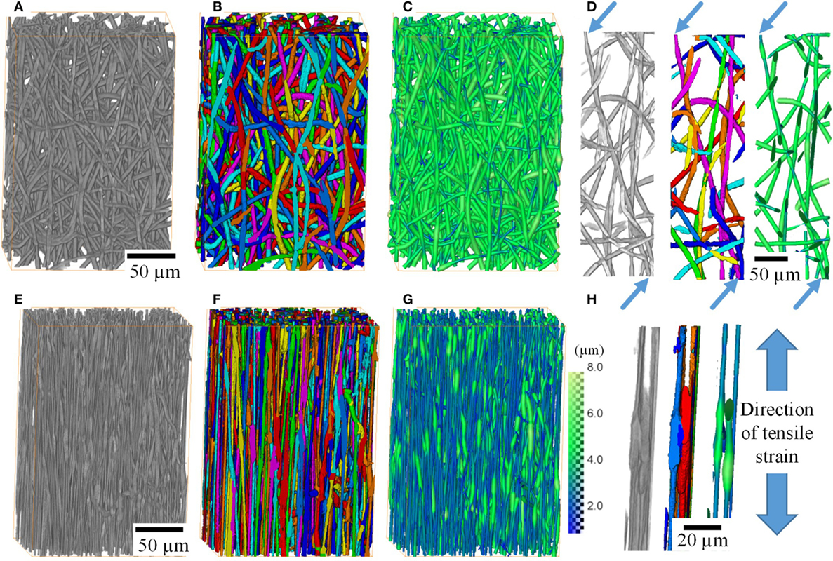
Figure 3. 3D rendering of small volumes of the P(3HB-co-4HB) fiber mats before any deformation (A––H) after application of 352% strain. Images show 3D volume rendering after filtering (A,E), segmentation of individual fibers (B,F) and with fiber thickness displayed as color intensity (C,G). Fibers can be traced and segmented accurately, enabling identification of individual fibers (D) and contact points between these (H). Scans of the fiber mats were performed unstrained and after loading. Loaded samples were left to stabilize for 5 min at constant strain before scanning in their loaded state.
Orientation of Fibers within Fiber Mat
Radiographic images and 3D rendering showed, qualitatively, fiber reorientation and alignment in the direction of the applied force. Segmentation of individual fibers on 3D tomographic data allowed orientation of each individual fiber to be quantified. Figures 4A–D show 3D images of small sections of the fiber mat with fibers colored according to their in-plane orientation (θ) from 0° (blue) to 90° (green-yellow) and scatter plot of fiber orientation on polar coordinates θ (in-plane, 0–90°) and Φ (out-of-plane, 0–360°). It is apparent that unstrained it exhibits an out-of-plane (Φ) orientation as shown in Figures 4A–D where the scatter is concentrated around 90° and 270°. This is expected as electrospinning results in continuous fibers being deposited on top of each other leading to an alignment in the out-of-plane direction, i.e., fibers lie flat on the surface of the collector therefore their long axis is aligned parallel to the surface of the collector. Although there is not a clear in-plane alignment, Figure 4A scatter plot shows that a large fraction of fibers are scattered within 45° suggesting that there is a higher number of fibers aligned in the direction perpendicular to electrospinning. This could explain the higher strength observed in the perpendicular direction compared to parallel direction (Figure 1). After 33% strain (Figure 4B), fibers do not show noticeable difference in alignment to unstrained. However, once strained to ~190% (Figure 4C) and ~350% (Figure 4D) the majority, if not all the fibers, are realigned in the 0°.
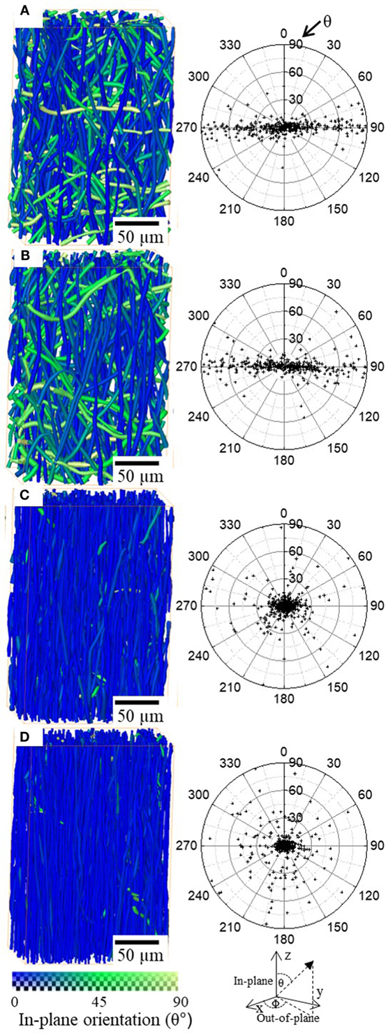
Figure 4. 3D rendering of small volumes of the P(3HB-co-4HB) fiber mats unstrained (A) 33% strain (B), 193% strain (C), and 352% strain (D). The color map at the bottom represent in-plane (θ) fiber orientation. Scatter plots of the fiber orientation is plotted with in-plane (θ) and out-of-plane (Φ) polar coordinates for all the fibers in the volumes.
Distributions of Fiber Diameter
Figures 5A–D shows a 3D rendering of the fiber mats strained to various extents. Fiber realignment and thinning are clearly visible. It also shows that all the fibers in the fiber mat thin after deformation, however, undeformed segments are still visible even at 352% deformation. Fiber diameter distributions are also plotted in Figure 5E and summarized in Table 1. Mathematica was used to fit mixed-Gaussian distributions to the fiber diameter distribution solving for Eq. 1
where μ1 and μ2 the mean, σ1 and σ2 are the standard deviations for distributions 1 and 2, respectively, α is the fraction of distribution 1, (1-α) the fraction of distribution 2.
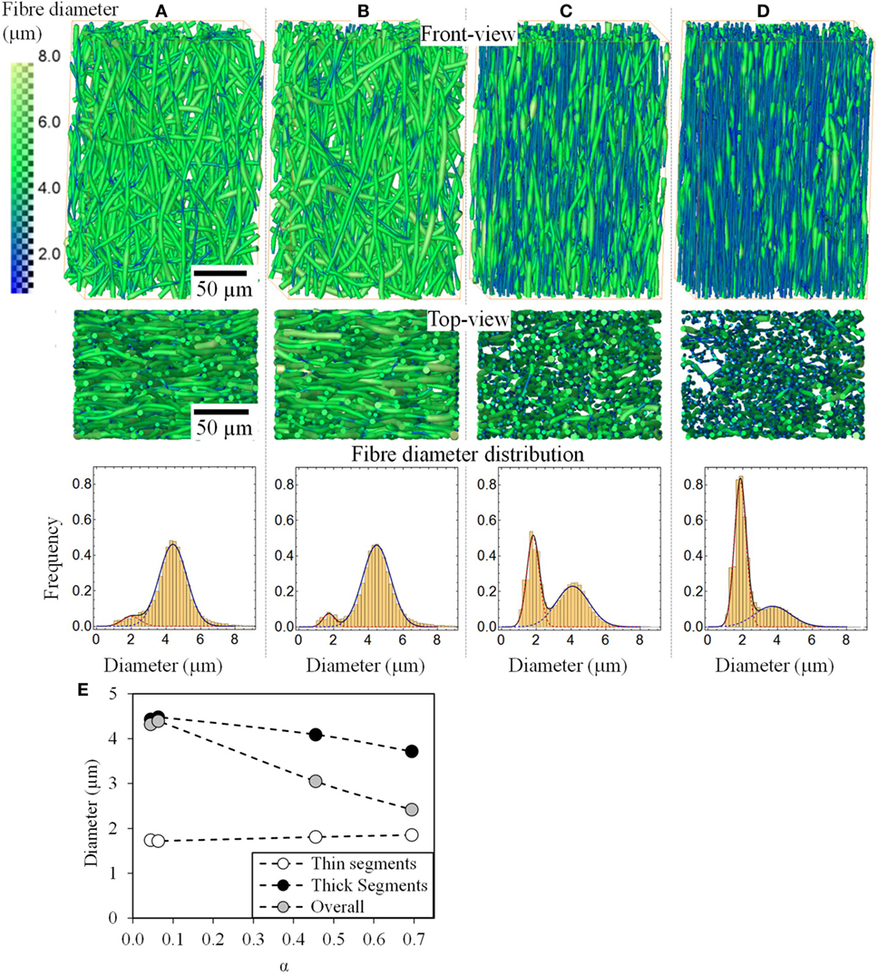
Figure 5. Front and top view 3D rendering of small volumes of the P(3HB-co-4HB) fiber mats and fiber diameter distributions for the unstrained (A), 33% (B), 193% (C), and 352% strained (D). The color map on the left represents fiber diameter in micrometers. The fiber diameters could be fitted with a bimodal Gaussian distribution. The modes of the overall and the two distributions are also plotted in (E) as a function of their fraction (α).
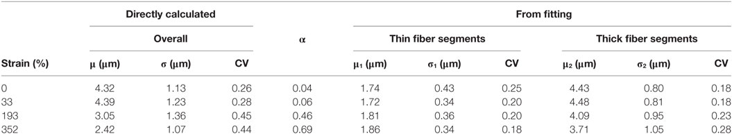
Table 1. Summary of modal fiber diameters (μ, μ1, μ2), standard deviations (σ, σ1, σ2), fraction (α), and coefficient of variation (CV) obtained from the fiber diameter distributions for the unstrained and samples strained to different deformations.
The overall mean fiber diameter decreases from 4.32 to 2.42 µm. At all the strains from 0 to 350%, the fiber diameter can be fitted with a bimodal distribution of “thin” segments and “thick” segments with a mode between μ1 = 1.72 to 1.86 µm and μ2 = 3.71 to 4.48 µm, respectively. The unstrained sample has 4% population of the fibers (α) which are “thin” with a mode of μ1 = 1.74 μm and the rest (1-α = 96%) are the thick segments with a mode of μ2 = 4.43 μm. It is clear from the images that these two populations, thin and thick segments, do not arise from two individual populations of fibers of different fiber diameters, but rather individual fibers exhibit thin and thick segments. The fact that the unstrained sample has a bimodal distribution suggests that the fibers, although homogenous, exhibit a small population of thin segments even before any deformation. These thin regions could have formed during the electrospinning process as demonstrated by Zussman et al. (2003). Figure 5E shows the changes in μ1, μ2, and overall fiber diameter as a function of total fraction of fiber diameters within distribution 1 (α). α increases with increasing strain, suggesting that the proportions of thin segments increase with strain. This is supported by the 3D rendered images in Figure 5. With increasing strain, the total fraction of fibers with fiber diameter in the 1st distribution, increases from 4 to 69% however its modal fiber diameter, μ1, remains largely unchanged. On the other hand, the fraction of thick fibers (2nd distribution) decreases from 96 to 31% and its mode, μ2, decreases from 4.43 to 3.71 µm. Interestingly, the coefficient of variation (CV = σ/μ) for the two distributions remain fairly constant with increasing strain, in comparison, the CV of the overall fiber diameter which is seen to increase significantly. This suggests that with increasing strain the fibers are simply being stretched, forming necks where these necks have a diameter that falls directly in the “thin” segment (1st distribution), i.e., a gradual decrease in fiber diameter seen with conventional fibers that fail by necking was not observed here, rather a shift from “thick” unstrained fibers to necked “thin” fibers is found.
Fiber Deformation and Necking
Thin segments which are necks in the strained samples are also observed in the unstrained sample (Figure 5A). It is possible that these pre-existing thin segments could have acted as locations for stress concentration for deformation to initiate and propagate. Such thin sections could have formed during the fabrication process where during electrospinning large extensional forces are transmitted through a solidifying fiber which could lead to cold stretching and neck formation (Zussman et al., 2003; Richard-Lacroix and Pellerin, 2013). There is however controversy surrounding this. Reports have suggested that necking/thin segments only form when fibers are collected on rotating disk collectors that is spun as fast as 5 m s−1 and are not observed when spun on flat plate collectors (Richard-Lacroix and Pellerin, 2013). In this study, a rotating drum collector spun at a rate of 0.08 m s−1 was used. This is unlikely to induce any cold drawing on the depositing fibers. Further, cold drawing induced necking has mainly been observed in fibers <500 nm in diameter. This suggests that the fiber mats may have experienced mechanical deformation post-synthesis and during sample handling.
Thin sections are regions of stress concentration where deformation initiates and grows at the expense of the thick segments. It seems that the thin segments become strain hardened (Haward, 2007) and pull on the unstrained thicker regions at its ends leading to further deformation and eventual network failure. However, at the highest strain, just before failure, a large number of thick segments are present in the fiber mat. This suggests that these are regions of high strength. Closer investigation reveals that these remaining thick segments are regions where fibers are bonded to their neighbors (Figure 3H). Fusion of the fibers leads to enhanced load transfer between the fibers, increasing its tensile strength. It was shown in the literature that fusion of fibers enhances tensile strength and elastic modulus of the fiber mat (Xiaofan et al., 2009).
Figure 6 shows thick segment-Pair Correlation Functions, g(r) for the unstrained, 33, 193, and 352% strained samples. When g(r) has values less than 1, this indicates a tendency for repulsion between particles, whereas values larger than 1 indicate aggregation and 1 represents a random distribution. Correlation function for all the samples below distances of 5–7 µm is less than 1 as the diameter of two thick segments is of these lengths therefore they are seen to repel each other. However, at higher distances both, unstrained and 33% strained samples quickly approach 1 meaning that the thick segments exhibit no particular clustering patterns at this stage. However, in the case of fiber mats strained to 193 and 352% g(r) peaks at roughly 1.5 and 2, respectively, at distances of 5–10 µm, before returning to values close to 1, i.e., at large strains, the thick segments in the fiber mats are shown to be aggregated. This suggests that with increasing strain thick segments remaining unstrained are very close to each other and hence likely are mutually bonded at those regions therefore are stronger than the rest of the fibers. This therefore means that there is a degree of fiber–fiber coupling present within the fiber mat. However, since a large extent of fiber realignment and fiber stretching was observed in these fiber mats, it indicates that the fiber–fiber coupling (crosslinking density) is low (Zundel et al., 2017).
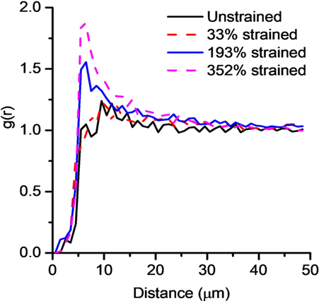
Figure 6. Pair correlation function for thick segments (>3.7μm) for the unstrained fiber mat and fiber mats strained to 33, 193, and 352%.
Conclusion
Synchrotron X-ray phase contrast imaging of electrospun biodegradable polyester (P(3HB-co-4HB)) non-woven fiber mats has revealed that prior to failure, the fibers reorient significantly in the direction of the applied strain, followed by significant fiber thinning by a characteristic mode of localized necking and neck growth. Once strained, the fibers, with original diameter of 4.3 µm, thinned without a gradual reduction in fiber diameter, leading to a distinct bimodal distribution of fiber diameters with modes at 1.9 and 3.7 µm. As-made fiber mats were also observed to have fibers with thin regions, these regions may have acted as seeds for necks to form and grow. Results, here, also highlight that the bonded regions/contact points between fibers remained thick (largely unstrained) right up until failure thus suggesting that the fibers were strongly coupled to each other but that the degree of coupling (number of nodes) was low. This paper presents novel insights into the failure mechanism of electrospun fiber mats, the relationship between contact points and deformation behavior and highlights the value of performing 3D in situ X-ray CT measurements of entire electrospun fiber mats.
This study has demonstrated that it is important to study not only the deformation of individual fibers, but the entire fiber mat network to understand its failure mechanism in a holistic approach. Electron microscopy is required to resolve individual nanofibers and their deformation, optical microscopy is ideal to image the entire fiber mats, while, high resolution synchrotron CT as performed in this study complements these techniques and sits well in the intermediate length scale in studying structure–property relationship of materials. The application of high resolution CT has shed light on novel mechanisms of fiber deformation though necking and neck growth of highly elastic P(3HB-co-4HB) polyester fiber mats. It has shown that the fibers realign and then thin between bonded regions which act as branches through which stress is distributed to the individual fibers. Further studies are planned where X-ray induced damage to samples is negligible such that a single sample could be strained to multiple strains at higher resolution. This will allow us to resolve structure–property relationships of the fiber mats in a truly 4D manner.
Author Contributions
JM, OT, PL, and GP designed the experiments and participated in the beamtime where the tensile test and image acquisition were performed. AO, CG, and TK produced the fiber mats and performed all the initial characterization. RB created the segmentation pipeline and quantification of Pair correlation function, meanwhile JM and GP processed the CT data and produced images. WS analyzed distributions of fiber diameters in Mathematica and plotted figures. The draft of the paper was produced by GP, JM, AO, and RB. PW, WS, TK, and GP supervised the work and contributed to the final version of the manuscript.
Conflict of Interest Statement
The authors declare that the research was conducted in the absence of any commercial or financial relationships that could be construed as a potential conflict of interest.
Acknowledgments
JM and GP would like to acknowledge facilities and support provided by the University of Manchester and Research Complex at Harwell (RCaH). Diamond Light Source and Diamond Manchester Collaboration for beamtime MT14367. We would like to thank Professor Andre Phillion and Dr. Loic Courtois for helping with tensile testing. Furthermore, we would like to thank Dr Andrew Bodey for helping to set up the scans and Dr Kazimir Wenelik for helping with image reconstruction scrips.
Funding
JM, GP, and PL would like to acknowledge EPSRC and MRC for funding (EP/L014904/1, EP/M023877/1, EP/I02249X/1, and EP/M009688/1). PW is grateful for a European Research Council for funding COREL-CT under grant No 695638. AO and TK would like to acknowledge JSPS for funding (JSPS KAKENHI #16K14403).
Supplementary Material
The Supplementary Material for this article can be found online at http://www.frontiersin.org/articles/10.3389/fmats.2017.00043/full#supplementary-material.
Video S1. Video showing tensile deformation of fiber mat.
References
Anjum, A., Zuber, M., Zia, K. M., Noreen, A., Anjum, M. N., and Tabasum, S. (2016). Microbial production of polyhydroxyalkanoates (PHAs) and its copolymers: a review of recent advancements. Int. J. Biol. Macromol. 89, 161–174. doi: 10.1016/j.ijbiomac.2016.04.069
Atwood, R. C., Bodey, A. J., Price, S. W. T., Basham, M., and Drakopoulos, M. (2015). A high-throughput system for high-quality tomographic reconstruction of large datasets at Diamond Light Source. Philos. Trans. R. Soc. A Math. Phys. Eng. Sci. 373, 20140398. doi:10.1098/rsta.2014.0398
Badami, A. S., Kreke, M. R., Thompson, M. S., Riffle, J. S., and Goldstein, A. S. (2006). Effect of fiber diameter on spreading, proliferation, and differentiation of osteoblastic cells on electrospun poly(lactic acid) substrates. Biomaterials 27, 596–606. doi:10.1016/j.biomaterials.2005.05.084
Baker, S. R., Banerjee, S., Bonin, K., and Guthold, M. (2016). Determining the mechanical properties of electrospun poly-ε-caprolactone (PCL) nanofibers using AFM and a novel fiber anchoring technique. Mater. Sci. Eng. C 59, 203–212. doi:10.1016/j.msec.2015.09.102
Cheng, M.-L., Chen, P.-Y., Lan, C.-H., and Sun, Y.-M. (2011). Structure, mechanical properties and degradation behaviors of the electrospun fibrous blends of PHBHHx/PDLLA. Polymer 52, 1391–1401. doi:10.1016/j.polymer.2011.01.039
Greiner, A., and Wendorff, J. H. (2007). Electrospinning: a fascinating method for the preparation of ultrathin fibers. Angew. Chem. Int. Ed. Engl. 46, 5670–5703. doi:10.1002/anie.200604646
Guarino, V., Cirillo, V., Taddei, P., Alvarez-Perez, M. A., and Ambrosio, L. (2011). Tuning size scale and crystallinity of PCL electrospun fibres via solvent permittivity to address hMSC response. Macromol. Biosci. 11, 1694–1705. doi:10.1002/mabi.201100204
Haward, R. N. (2007). Strain hardening of high density polyethylene. J. Polym. Sci. B Polym. Phys. 45, 1090–1099. doi:10.1002/polb.21123
Hildebrand, T., and Rüegsegger, P. (1997). A new method for the model-independent assessment of thickness in three-dimensional images. J. Microsc. 185, 67–75. doi:10.1046/j.1365-2818.1997.1340694.x
Jamshidian, M., Tehrany, E. A., Imran, M., Jacquot, M., and Desobry, S. (2010). Poly-lactic acid: production, applications, nanocomposites, and release studies. Compr. Rev. Food Sci. Food Saf. 9, 552–571. doi:10.1111/j.1541-4337.2010.00126.x
Jose, M. V., Thomas, V., Johnson, K. T., Dean, D. R., and Nyairo, E. (2009). Aligned PLGA/HA nanofibrous nanocomposite scaffolds for bone tissue engineering. Acta Biomater. 5, 305–315. doi:10.1016/j.actbio.2008.07.019
Kim, K. W., Lee, K. H., Khil, M. S., Ho, Y. S., and Kim, H. Y. (2004). The effect of molecular weight and the linear velocity of drum surface on the properties of electrospun poly(ethylene terephthalate) nonwovens. Fibers Polym. 5, 122–127. doi:10.1007/BF02902925
Lee, K. H., Kim, H. Y., La, Y. M., Lee, D. R., and Sung, N. H. (2002). Influence of a mixing solvent with tetrahydrofuran and N,N-dimethylformamide on electrospun poly(vinyl chloride) nonwoven mats. J. Polym. Sci. B Polym. Phys. 40, 2259–2268. doi:10.1002/polb.10293
Li, Z., and Loh, X. J. (2017). Recent advances of using polyhydroxyalkanoate-based nanovehicles as therapeutic delivery carriers. Wiley Interdiscip. Rev. Nanomed. Nanobiotechnol. 9, e1429. doi:10.1002/wnan.1429
Liu, Y., Chen, S., Zussman, E., Korach, C. S., Zhao, W., and Rafailovich, M. (2011). Diameter-dependent modulus and melting behavior in electrospun semicrystalline polymer fibers. Macromolecules 44, 4439–4444. doi:10.1021/ma200262z
Lu, J.-W., Zhang, Z.-P., Ren, X.-Z., Chen, Y.-Z., Yu, J., and Guo, Z.-X. (2008). High-elongation fiber mats by electrospinning of polyoxymethylene. Macromolecules 41, 3762–3764. doi:10.1021/ma702881k
Makadia, H. K., and Siegel, S. J. (2011). Poly lactic-co-glycolic acid (PLGA) as biodegradable controlled drug delivery carrier. Polymers (Basel) 3, 1377–1397. doi:10.3390/polym3031377
Mohammadzadehmoghadam, S., Dong, Y., and Davies, I. J. (2016). Modeling electrospun nanofibers: an overview from theoretical, empirical, and numerical approaches. Int. J. Polym. Mater. Polym. Biomater. 65, 901–915. doi:10.1080/00914037.2016.1180617
Nagel, W. (1995). Stoyan, D./Stoyan, H.: Fractals, Random Shapes and Point Fields. Methods of Geometrical Statistics. John Wiley & Sons, Chichester 1994, XIV, 389 pp. £39.95. Biom. J. 37, 978–978. doi:10.1002/bimj.4710370810
Naraghi, M., Chasiotis, I., Kahn, H., Wen, Y., and Dzenis, Y. (2007). Mechanical deformation and failure of electrospun polyacrylonitrile nanofibers as a function of strain rate. Appl. Phys. Lett. 91, 151901. doi:10.1063/1.2795799
Nishizuka, T., Kurahashi, T., Hara, T., Hirata, H., and Kasuga, T. (2014). Novel intramedullary-fixation technique for long bone fragility fractures using bioresorbable materials. PLoS ONE 9:e104603. doi:10.1371/journal.pone.0104603
Pedicini, A., and Farris, R. J. (2003). Mechanical behavior of electrospun polyurethane. Polymer 44, 6857–6862. doi:10.1016/j.polymer.2003.08.040
Poologasundarampillai, G., Wang, D., Li, S., Nakamura, J., Bradley, R., Lee, P. D., et al. (2014). Cotton-wool-like bioactive glasses for bone regeneration. Acta Biomater. 10, 3733–3746. doi:10.1016/j.actbio.2014.05.020
Poologasundarampillai, G., Yu, B., Jones, J. R., and Kasuga, T. (2011). Electrospun silica/PLLA hybrid materials for skeletal regeneration. Soft Matter 7, 10241–10251. doi:10.1039/c1sm06171b
Puncreobutr, C., Lee, P. D., Hamilton, R. W., and Phillion, A. B. (2012). Quantitative 3D characterization of solidification structure and defect evolution in Al alloys. JOM 64, 89–95. doi:10.1007/s11837-011-0217-9
Rau, C., Wagner, U., Pešić, Z., and De Fanis, A. (2011). Coherent imaging at the diamond beamline I13. Phys. Status Solidi A 208, 2522–2525. doi:10.1002/pssa.201184272
Richard-Lacroix, M., and Pellerin, C. (2013). Molecular orientation in electrospun fibers: from mats to single fibers. Macromolecules 46, 9473–9493. doi:10.1021/ma401681m
Rigort, A., Gunther, D., Hegerl, R., Baum, D., Weber, B., Prohaska, S., et al. (2012). Automated segmentation of electron tomograms for a quantitative description of actin filament networks. J. Struct. Biol. 177, 135–144. doi:10.1016/j.jsb.2011.08.012
Ripley, B. D. (1976). The second-order analysis of stationary point processes. J. Appl. Probab. 13, 255–266. doi:10.2307/3212829
Rizvi, M. S., Kumar, P., Katti, D. S., and Pal, A. (2012). Mathematical model of mechanical behavior of micro/nanofibrous materials designed for extracellular matrix substitutes. Acta Biomater. 8, 4111–4122. doi:10.1016/j.actbio.2012.07.025
Rizvi, M. S., and Pal, A. (2014). Statistical model for the mechanical behavior of the tissue engineering non-woven fibrous matrices under large deformation. J. Mech. Behav. Biomed. Mater. 37, 235–250. doi:10.1016/j.jmbbm.2014.05.026
Saito, Y., and Doi, Y. (1994). Microbial synthesis and properties of poly(3-hydroxybutyrate-co-4-hydroxybutyrate) in Comamonas acidovorans. Int. J. Biol. Macromol. 16, 99–104. doi:10.1016/0141-8130(94)90022-1
Sill, T. J., and von Recum, H. A. (2008). Electrospinning: applications in drug delivery and tissue engineering. Biomaterials 29, 1989–2006. doi:10.1016/j.biomaterials.2008.01.011
Tan, E. P. S., and Lim, C. T. (2004). Physical properties of a single polymeric nanofiber. Appl. Phys. Lett. 84, 1603–1605. doi:10.1063/1.1651643
Teo, W. E., and Ramakrishna, S. (2006). A review on electrospinning design and nanofibre assemblies. Nanotechnology 17, R89–R106. doi:10.1088/0957-4484/17/14/R01
Türesin, F., Gürsel, I., and Hasirci, V. (2001). Biodegradable polyhydroxyalkanoate implants for osteomyelitis therapy: in vitro antibiotic release. J. Biomater. Sci. Polym. Ed. 12, 195–207. doi:10.1163/156856201750180924
Vigneswari, S., Murugaiyah, V., Kaur, G., Abdul Khalil, H. P. S., and Amirul, A. A. (2016). Simultaneous dual syringe electrospinning system using benign solvent to fabricate nanofibrous P(3HB-co-4HB)/collagen peptides construct as potential leave-on wound dressing. Mater. Sci. Eng. C Mater. Biol. Appl. 66, 147–155. doi:10.1016/j.msec.2016.03.102
Weber, B., Greenan, G., Prohaska, S., Baum, D., Hege, H. C., Muller-Reichert, T., et al. (2012). Automated tracing of microtubules in electron tomograms of plastic embedded samples of Caenorhabditis elegans embryos. J. Struct. Biol. 178, 129–138. doi:10.1016/j.jsb.2011.12.004
Xiaofan, W., Zhenhai, X., Shing-Chung, W., and Avinash, B. (2009). Modelling of mechanical properties of electrospun nanofibre network. Int. J. Exp. Comput. Biomech. 1, 45–57. doi:10.1504/IJECB.2009.022858
Yano, T., Higaki, Y., Tao, D., Murakami, D., Kobayashi, M., Ohta, N., et al. (2012). Orientation of poly(vinyl alcohol) nanofiber and crystallites in non-woven electrospun nanofiber mats under uniaxial stretching. Polymer 53, 4702–4708. doi:10.1016/j.polymer.2012.07.067
Yu, M.-F., Files, B. S., Arepalli, S., and Ruoff, R. S. (2000). Tensile loading of ropes of single wall carbon nanotubes and their mechanical properties. Phys. Rev. Lett. 84, 5552–5555. doi:10.1103/PhysRevLett.84.5552
Zhijiang, C., Qin, Z., Xianyou, S., and Yuanpei, L. (2017). Zein/poly(3-hydroxybutyrate-co-4-hydroxybutyrate) electrospun blend fiber scaffolds: preparation, characterization and cytocompatibility. Mater. Sci. Eng. C 71, 797–806. doi:10.1016/j.msec.2016.10.053
Zundel, M., Mazza, E., and Ehret, A. E. (2017). A 2.5D approach to the mechanics of electrospun fibre mats. Soft Matter 13, 6407–6421. doi:10.1039/c7sm01241a
Zussman, E., Burman, M., Yarin, A. L., Khalfin, R., and Cohen, Y. (2006). Tensile deformation of electrospun nylon-6,6 nanofibers. J. Polym. Sci. B Polym. Phys. 44, 1482–1489. doi:10.1002/polb.20803
Keywords: scaffolds, in situ, fiber necking, tissue regeneration, synchrotron X-ray
Citation: Maksimcuka J, Obata A, Sampson WW, Blanc R, Gao C, Withers PJ, Tsigkou O, Kasuga T, Lee PD and Poologasundarampillai G (2017) X-ray Tomographic Imaging of Tensile Deformation Modes of Electrospun Biodegradable Polyester Fibers. Front. Mater. 4:43. doi: 10.3389/fmats.2017.00043
Received: 11 September 2017; Accepted: 04 December 2017;
Published: 21 December 2017
Edited by:
Gianluca Tozzi, University of Portsmouth, United KingdomReviewed by:
Maria Letizia Focarete, Università di Bologna, ItalyKheng Lim Goh, Newcastle University, United Kingdom
Copyright: © 2017 Maksimcuka, Obata, Sampson, Blanc, Gao, Withers, Tsigkou, Kasuga, Lee and Poologasundarampillai. This is an open-access article distributed under the terms of the Creative Commons Attribution License (CC BY). The use, distribution or reproduction in other forums is permitted, provided the original author(s) or licensor are credited and that the original publication in this journal is cited, in accordance with accepted academic practice. No use, distribution or reproduction is permitted which does not comply with these terms.
*Correspondence: Akiko Obata, b2JhdGEuYWtpa29Abml0ZWNoLmFjLmpw;
Gowsihan Poologasundarampillai, Zy5wb29sb0BtYW5jaGVzdGVyLmFjLnVr