 Akira Kawai
 Tatsuhiko Maeda
 Izuru Takewaki
- 1Department of Architecture and Architectural Engineering, Graduate School of Engineering, Kyoto University, Kyotodaigaku-Katsura, Kyoto, Japan
- 2Structural Design Division, Takenaka Co., Osaka, Japan
An innovative structural control system is proposed for high-rise buildings. A damping layer is provided between a stiff upper core frame suspended from the top of the main building and a stiff lower core frame connected to the building foundation. As the ratio of stiffness of both core frames to that of the main building becomes larger, the relative displacement in the damping layer (damper deformation) approaches to the top floor displacement of the main building. The large displacement of the top floor displacement of the main building is taken full advantage in the proposed control system as most of the total displacement of the main building results from the damper deformation instead of interstory drift. Transformation of the multi-degree-of-freedom (MDOF) model into the single-degree-of-freedom (SDOF) model enables a simplified but rather accurate response evaluation for pulse-type and long-duration earthquake ground motions. The results of the time history response analysis of buildings including this control system are presented for various recorded ground motions. Finally, the effectiveness of the proposed structural control system is discussed from the viewpoint of earthquake input energy.
Introduction
After emerging in the 1980s and 1990s (Leipholz, 1980; Leipholz and Abdel-Rohman, 1986; Housner et al., 1997), the technique of structural control using active and passive control mechanisms has become main stream in structural engineering for tall and special buildings, e.g., base-isolated buildings (Hanson and Soong, 2001; Christopoulos and Filiatrault, 2006; Takewaki, 2009; Lagaros et al., 2012; Domenico et al., 2019). For civil and building structures, passive control plays a central role. This is because of increased demand for taller buildings and the introduction of new construction materials, accelerating the development of new techniques in the field of passive structural control (for example, Takewaki, 1997; Garcia, 2001; Lavan and Levy, 2005; Aydin et al., 2007; Silvestri and Trombetti, 2007; Whittle et al., 2012). However, the characteristics of near-fault and long-duration ground motions can have a significant effect on tall building response. The effects of near-fault ground motions and long-duration/long-period ground motions on tall and base-isolated buildings have been investigated in detail (Hall et al., 1995; Takewaki et al., 2011). The advantage of passive control systems is that they are robust to unexpected disturbances (Takewaki, 2007, 2009).
Various passive structural control systems exist for tall buildings (Takewaki, 2009; Lagaros et al., 2012; Fukumoto and Takewaki, 2015, 2017; Tani et al., 2017; Domenico et al., 2019). The most popular includes the interstory-type (Takewaki, 2009; Lagaros et al., 2012; Domenico et al., 2019) and soft first story-type (Tani et al., 2017). However, passive structural control systems, able to respond to both near-fault ground motions and long-duration/ long-period ground motions, are very limited (Murase et al., 2013; Fukumoto and Takewaki, 2015, 2017; Hayashi et al., 2018). Structural control via passive control devices is difficult for near-fault ground motions because the earthquake energy input is made during very short time interval. For near-fault ground motions, base-isolation system attaining an un-resonant state can be an effective technique. However, base-isolation system requires large site areas to prevent impact to retaining walls and increases construction cost. Moreover, base-isolation systems are vulnerable to resonant long-duration/long-period ground motions.
In this paper, a new structural control system is proposed for high-rise buildings. In this system, a sub core frame is located along a main building and a damping layer is provided between a stiff upper core frame suspended from the top of the main building and a stiff lower core frame (strong-back core frame) attached to the building foundation. Although, the concept is not the same, the strong-back core frame system was investigated in the past (Lai and Mahin, 2015; Palermo et al., 2018). The previous strong-back core frame system aimed at avoiding the plastic deformation concentrations in a few stories by distributing the frame deformations to many stories. The large displacement of the top floor displacement of the main building is taken full advantage in the proposed control system. Transformation of the multi-degree-of-freedom (MDOF) model into the single-degree-of-freedom (SDOF) model enables a simplified but rather accurate response evaluation for pulse-type and long-duration earthquake ground motions which are represented by the double impulse and the multi impulse, respectively. While passive viscous dampers are effective for long-duration ground motions owing to the sufficient time for energy dissipation, they are not necessarily effective for near-fault ground motions. These properties are also investigated in the proposed passive control system. The results of the time history response analysis of buildings including this control system are presented for various recorded ground motions. Finally, the effectiveness of the proposed structural control system is discussed from the viewpoint of earthquake input energy in which the original energy transfer function plays a central role (Housner, 1959, 1975; Berg and Thomaides, 1960; Housner and Jennings, 1975; Zahrah and Hall, 1984; Uang and Bertero, 1990; Ordaz et al., 2003; Takewaki, 2004a,b).
Proposed Passive Control System Using Large-Stroke Viscous Dampers Through Connection to Strong-Back Core Frame
System Overview
Consider a passive control system using large-stroke viscous dampers connected to a strong-back core frame, as shown in Figure 1A. This control system is proposed to reduce the seismic response of high-rise buildings. It is assumed that the main building is used for an apartment house and the lower strong-back core frame is used for car parking. The upper strong-back core frame is used only for the stiffness element connecting the top of the main frame to the lower strong-back core frame. To enable the efficient use of passive dampers, a stiff core (strong-back core frame) is constructed and attached to the foundation. Another stiff core frame is hung from the top story stiff sub-assemblage of the main building. The height of the lower strong-back core frame is determined from the architectural user demand based on the number of parked cars. Because this lower strong-back core frame is made of a wall-type reinforced concrete structure with relatively small mass, the horizontal force demand is not significant. Since deformation, or story drift demand, is concentrated in the connecting story, a large stroke is required for viscous dampers. Oil dampers of large stroke typically used usually for base-isolation systems are employed in this system.
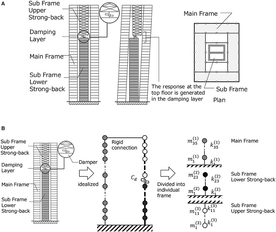
Figure 1. Proposed control system using large-stroke viscous dampers through connection to strong-back core frame. (A) Overview of building with control system and (B) Simplification of controlled building system into MDOF model and decomposition into subassemblage models.
Simplification of Controlled Building System Into MDOF Model
The building structure including the proposed control system can be represented by a linear MDOF system as shown in Figure 1B. The main building structure is a reinforced concrete structure of 35 stories. The subsystem consists of two subassemblages, i.e., the lower strong-back core frame and the upper strong-back core frame as shown in Figure 1A. Since a sub frame of large stiffness is required in the upper strong-back, braced systems were used for the upper strong-back. Large-stroke viscous dampers (oil dampers) were installed at the connection layer of the lower and upper strong-back core frames, as shown in Figure 1A. The total damping coefficient of those large-stroke viscous dampers is denoted by Cd. The fundamental natural period of the total system by complex eigenvalue analysis was 2.24(s). It is possible to decompose the overall system into three subassemblages with fixed boundaries to characterize the component properties, as shown in Figure 1B. This division was made for defining the stiffnessses of three parts. The masses of the main building and the strong-back core frames were determined from the data of a project building. The fundamental natural periods of these three subassemblages (main building, lower strong-back core frame and upper strong-back core frame) are 2.20, 1.06, 0.51(s). The structural damping is considered only in the main building and the damping ratio is 0.03. Eight oil dampers of 2500[kNs/m]-class are installed and the damping coefficients Cd=0 ~ 5.0 × 10⁷[Ns/m] are considered for parametric analysis. This model is treated as the original model. Because the stiffness of the upper and lower strong-back core frames affects the control performance of the proposed passive damper control system, another model with stiffer lower and upper strong-back core frames (10 times larger than the original) is used in later section for comparison (sections Seismic Response of Buildings Including Proposed Passive Control System and Its Simplified Evaluation Method and Earthquake Input Energy and Energy Transfer Function). The original model is described as “the Original Model” and the other model is called “the Stiffer Model.”
Eigenvalue Analysis of MDOF Model of Controlled Building System
Since the main building and the strong-back core frames have structural damping proportional to the stiffness and the passive viscous damper has an independent damping coefficient, the overall system has non-proportional damping. Complex eigenvalue analysis was performed for this model. Figure 2A shows the lowest-mode complex mode vector multiplied by the corresponding complex participation factor for three viscous damper damping coefficients for the Original Model. In upper figures, the absolute value, the real value and the imaginary values are plotted. In lower figures, the amplitudes and the phase angles of the lowest-mode complex mode vector at three points (top of the main frame, point just above the damper and point just below the damper) are shown. The distance between the point just above the damper and point just below the damper indicates the damper stroke. Figure 2B illustrates the lowest-mode complex eigenvector multiplied by the corresponding complex participation factor for three viscous damper damping coefficients for the Stiffer Model. It can be observed that the absolute value of the displacement of the subsystem becomes smaller as the damping coefficient becomes larger. In addition, the absolute value of the deformation of the connecting story becomes smaller after it becomes larger for some damper damping coefficient. This means that there exists an optimal damper damping coefficient that effectively reduces the deformation of the main building.
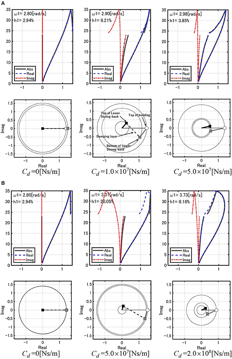
Figure 2. Lowest-mode complex eigenvector multiplied by complex participation factor for three viscous damper damping coefficients. (A) Original Model and (B) Stiffer Model.
Reduction of MDOF Model into SDOF Model Using Correction Factor on Damper Damping Coefficient
Since the MDOF model requires complex computation for the idealized inputs (double impulse for near-fault ground motion and multi impulse for long-duration ground motion) and recorded ground motions, a simple SDOF model is introduced to clarify the intrinsic earthquake response properties of the buildings including the proposed control system. The response evaluation method using this SDOF model is called “a simplified evaluation method”.
Let Mmain, kmain, and cmain denote the total mass of the main building, stiffness of the main building and structural damping coefficient of the main building as an SDOF model. In addition, let Mupper, kupper, klower denote the mass of the upper strong-back core frame, stiffness of the upper strong-back core frame, and stiffness of the lower strong-back core frame. The MDOF model is reduced to an equivalent SDOF model using the correction factor β on the damping coefficient Cd of dampers. This correction factor is introduced to account for various factors that could cause differences in damper behavior in the MDOF and SDOF models. A similar procedure was adopted in the reference (Hayashi et al., 2018). Let denote the corrected damping coefficient. At first, a transformation method from the MDOF model into an equivalent SDOF model with a Maxwell-type spring-dashpot model was introduced as shown in Figure 3 with the help of the correction factor. The stiffness ksub of the sub frame can be derived assuming that kupper and klower are in series. Then, the Maxwell-type spring-dashpot model is reduced to a Kelvin-Voigt model as shown in Figure 3. It was confirmed that, since a large deformation occurs at the connection between the upper core frame and the lower core frame and the mass of the main frame is much larger than both core frames, it is reasonable to disregard the mass of the lower core frame and regard the lower core frame as a spring. Table 1 presents the parameters of equivalent SDOF models of three subassemblages shown in Figure 1B for the Original Model.
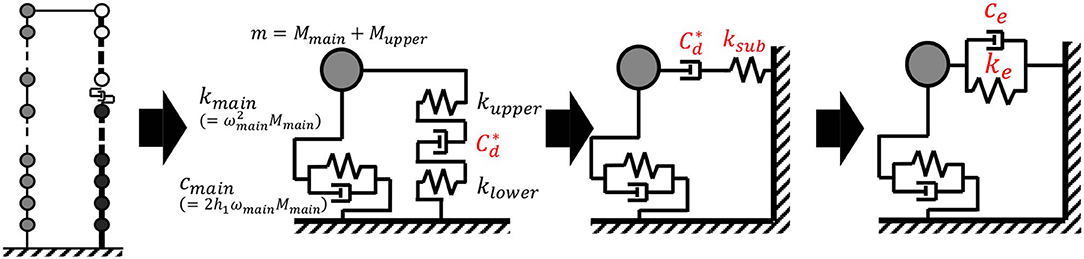
Figure 3. Reduction of MDOF model into equivalent SDOF model.
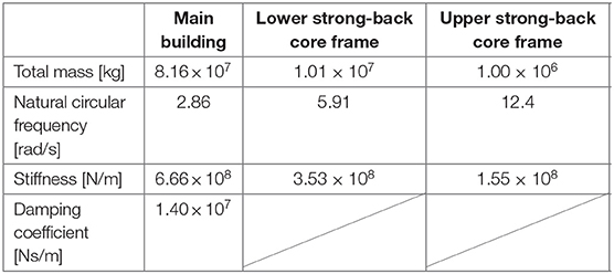
Table 1. Parameters of equivalent SDOF models of three subassemblages for Original Model.
In the transformation from the Maxwell-type spring-dashpot model to a Kelvin-Voigt model, the following relations on the frequency-dependent damping coefficient ce(ω) and the frequency-dependent stiffness ke(ω) are used.
Substitution of Equation (2) into Equation (1b) leads to the determination of ke. Subsequent substitution of ke into Equation (2) provides an approximate fundamental natural circular frequency ωe for the total system. ke(ωe) and ce(ωe) are used subsequently for time-history response analysis.
Figure 4 shows the computation flow of the damping coefficient of the viscous damper in the equivalent SDOF model to ensure the validity of using the SDOF model in the response evaluation in relation to the MDOF model. For the appropriate comparison of damping performance with respect to varied damper damping coefficient between the SDOF and MDOF models, a damping ratio normalized by the peak value is introduced and denoted by h with an overbar. The difference between the lowest damping ratios of the SDOF model and the MDOF model is used to evaluate the correction factor β. In this process, the condition is used. Figure 5 relates the original damping coefficient Cd of the viscous damper installed at the connection of the upper and lower strong-back core frames in the MDOF model and the damping coefficient of the corresponding viscous damper in the equivalent SDOF model for the Original Model and the Stiffer Model. The plot of the ‘calculated ' was evaluated by using the equivalence of the normalized lowest damping ratios between the MDOF model and the SDOF model. The increase of damper damping coefficient does not always lead to the reduction of responses because excessively large dampers introduce often induces the addition of complex stiffness. In this case, the damping ratio exhibits a local maximum with respect to damper damping coefficient. The ratio of the damping ratio to such maximum value can be used to assess the performance of the dampers. The ratio of the damping ratio to such maximum value was introduced for the MDOF model and the SDOF model. The plot was obtained by determining β at one value of Cd. The damping coefficients 8.92 × 10⁶[Ns/m] and 3.39 × 10⁷[Ns/m] were obtained from the MDOF and SDOF models for the Original Model such that the corresponding damping ratios attain peak values. Similarly, the damping coefficients 4.25 × 10⁷[Ns/m] and 1.95 × 10⁸[Ns/m] were obtained from the MDOF and SDOF models for the Stiffer Model. It can be observed that the proposed correction procedure is accurate enough. Figure 5 also demonstrates that, if the correction factor β is not introduced, i.e., β =1, a large error occurs in the response prediction by means of the SDOF model. In other words, a prediction error in the damper damping coefficient, 3.80 and 4.58 times, leads to a large error in the response evaluation.
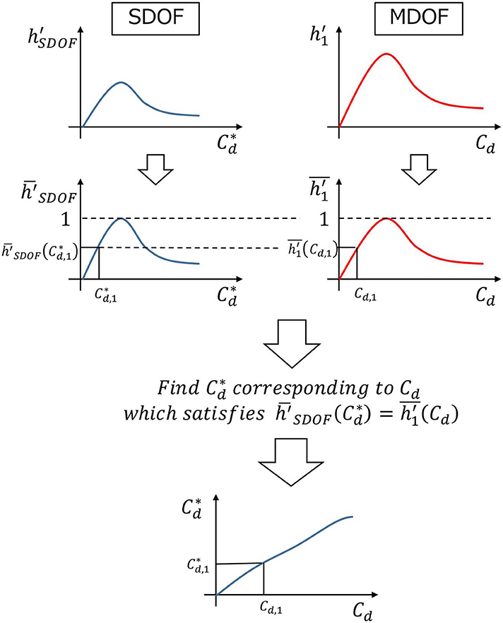
Figure 4. Computation flow of damping coefficient of viscous damper in equivalent SDOF model.
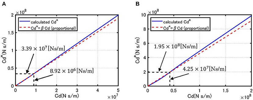
Figure 5. Relation of original damping coefficient of viscous damper in MDOF model and damping coefficient of viscous damper in equivalent SDOF model. (A) Original Model (β = 3.80) and (B) Stiffer Model (β = 4.58).
Seismic Response of Buildings Including Proposed Passive Control System and Its Simplified Evaluation Method
In this section, the seismic response of buildings including the proposed control system under idealized ground motions and recorded ground motions is investigated through the comparison with that of the simplified SDOF model introduced in the previous section.
Kojima and Takewaki (2015a) demonstrated that one-cycle sinusoidal wave is a good representation of the main part of pulse-type near-fault ground motions. This double impulse is a simplified version of one-cycle sinusoidal input. When a SDOF is resonant to one-cycle sinusoidal input, the response to the double impulse provides a good estimate of the response to one-cycle sinusoidal input. However, when a MDOF is used, the correspondence between the responses to the double impulse and one-cycle sinusoidal input is not guaranteed, even if both inputs are resonant to the fundamental mode of the MDOF. For this reason, the comparison of the responses of the MDOF under the double impulse and one-cycle sinusoidal input is shown here.
Response of Buildings Including Proposed Control System Subjected to Double Impulse and Its Simplified Evaluation Method
Consider the seismic response of buildings including the proposed passive control system and its simplified evaluation method. As a representative of near-fault ground motions, the double impulse resonant to the building is introduced (Kojima and Takewaki, 2015a). The acceleration input of the double impulse can be expressed by
where δ(t) is the Dirac's delta function, VI is the initial input velocity and t0 is the time interval of two impulses. The corresponding one-cycle sine wave can be described by
This one-cycle sine wave is introduced to ensure the validity of the double impulse in connection to actual near-fault ground motions. Some actual near-fault ground motions include an influential pulse-type motion which can be represented by one-cycle sine wave (see Kojima and Takewaki, 2016).
In Equation (4), ωp = π/t0 is the input circular frequency and is the damped fundamental natural period of the building. Vp1 is specified as Vp1 = 1.2222VI to guarantee the equivalence of the Fourier amplitudes of the double impulse and the one-cycle sine wave even at the first peak (Kojima et al., 2017). Let and he denote the damped natural circular frequency and the damping ratio of the SDOF model. Since the response after the first impulse is a free vibration with zero initial displacement and initial velocity=−VI, the displacement of the SDOF model after the first impulse can be expressed by
The displacement of the SDOF model is equal to the sum of the damper deformation ud and the deformation usub of the lower and upper cores:
Since the damper and the lower and upper core frames are in series, the force equivalence can be expressed by
From Equation (5), (6a, b), the damper deformation can be obtained from
The maximum displacement is obtained at time: from (see Figure 6A). The time t2 of the maximum deformation of the damper can be derived by substituting the condition into Equation (6):
as
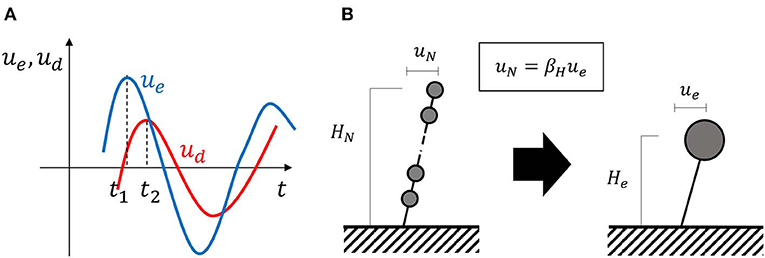
Figure 6. Time-history responses and height correction in SDOF transformation. (A) Times at maximum displacements and (B) Equivalent height in equivalent SDOF model.
In summary, the maximum displacement of the mass of the SDOF model and the maximum deformation of the damper can be described by ue(t1) and ud(t2) = ue(t2), respectively. Consider a critical excitation problem for maximizing the response after the second impulse where the velocity input amplitude VI is fixed and the interval t0 between two impulses is varied. Since the critical input of the second impulse is taken into account, the displacement of the mass of the SDOF model just before the beginning of the second impulse is 0 and its velocity is . Therefore, the vibration after the input of the second impulse corresponds to the free vibration from the initial displacement, =0, and the initial velocity, =. As a result, the maximum displacement of the mass of the SDOF model and the maximum deformation of the damper can be derived in terms of the damper damping coefficient Cd.
Since the displacement of the SDOF model mass is different from the top displacement of the MDOF model (see Figure 6B), the maximum top displacement of the MDOF model and the maximum damper deformation can be expressed in terms of the height ratio βH = HN/He (HN: height of MDOF model, He: height of equivalent SDOF model).
Figure 7 compares the maximum displacements from the closed-form expression for the SDOF model under the double impulse (VI = 0.10 [m/s]), the time-history response analysis for the MDOF model under the double impulse and the time-history response analysis for the MDOF model under the corresponding one-cycle sine wave. Two models were considered: the Original Model and the Stiffer Model. It can be observed that the response of the MDOF model under the double impulse approximates the response of the MDOF model under the corresponding one-cycle sine wave. The closed-form expression for the SDOF model underestimates the response of the MDOF model slightly. Although the displacement response reduction effect in the top displacement from the model without the damper is not remarkable in the Original Model, it is remarkable in the Stiffer Model.
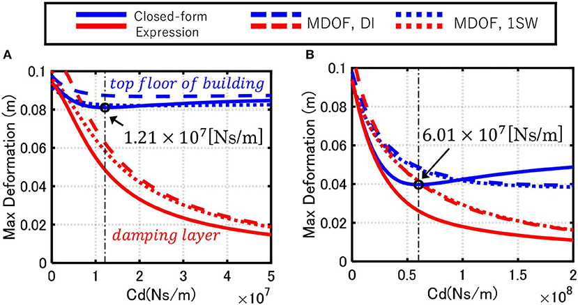
Figure 7. Comparison of maximum displacements among closed-form expression for SDOF model under double impulse, time-history response analysis for MDOF model under double impulse and time-history response analysis for MDOF model under one-cycle sine wave. (A) Original Model and (B) Stiffer Model.
Response of Buildings Including Proposed Control System Subjected to Multi Impulse and Its Simplified Evaluation Method
While the transient response was treated for the double impulse, the steady-state response is dealt with for the multi-impulse which can be used to approximate long-period, long-duration ground motion.
Consider the multi impulse expressed by
This input was introduced by Kojima and Takewaki (2015b) for approximating long-duration sinusoidal input (Takewaki et al., 2011):
When we consider the resonant input (the impulse is input at the zero displacement), the vibrations can be described by free vibration of the initial displacement, =0, and the initial velocity:
Note, when the input cycle N becomes infinity, the initial velocity at later cycles converges to
The maximum displacement of the equivalent SDOF model can be obtained as
The maximum deformation of the damper is given by
Similar to the input of the double impulse, the maximum top displacement of the MDOF model and the maximum damper deformation under the multi-impulse input can be expressed in terms of the height ratio βH = HN/He.
Figure 8 compares the maximum displacements from the closed-form expression for the SDOF model under the multi impulse, time-history response analysis for the MDOF model under the multi impulse, and time-history response analysis for the MDOF model under a 10-cycle sine wave (N=20). As in the case under the double impulse, the Original Model and the Stiffer Model were considered. The maximum response of the MDOF model under the multi impulse approximates that of the MDOF model under the corresponding 10-cycle sine wave. The closed-form expression using the SDOF model slightly underestimates the response of the MDOF model. The response reduction effect in the top displacement from the model without damper is significant even in the Original Model compared to the input of the double impulse. This characteristic is more significant in the Stiffer Model. An optimal damper damping coefficient exist in both the Original Model and the Stiffer Model. Note, the optimal damper damping coefficient can be obtained by using the SDOF model described in the next section.
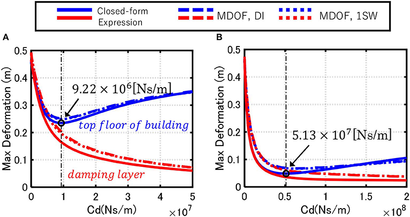
Figure 8. Comparison of maximum displacements among closed-form expression for SDOF model under multi impulse, time-history response analysis for MDOF model under multi impulse and time-history response analysis for MDOF model under 10-cycle sine wave. (A) Original Model and (B) Stiffer Model.
Response of Buildings Including Proposed Control System Subjected to Recorded Ground Motions and Its Simplified Evaluation Method
The response characteristics of the building with the proposed control system under recorded ground motions are investigated in this section for various damper damping coefficient.
Table 2 shows the employed recorded ground motions. The corresponding velocity response spectra are shown in Figure 9.
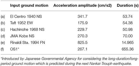
Table 2. Acceleration amplitude of input recorded ground motions.
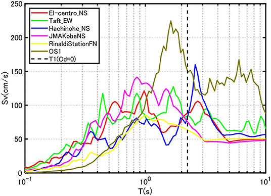
Figure 9. Velocity response spectra of input recorded ground motions.
Figure 10A presents the simplified evaluation of the maximum top displacement and the maximum damper deformation for the Original Model. The maximum top-story displacement and the maximum damper deformation are plotted with respect to the damper damping coefficient. Figure 10B indicates the corresponding evaluation for the Stiffer Model. While a slight difference exists in some ground motions, the proposed equivalent SDOF model provides a good approximate of the response of the MDOF model. Furthermore, the optimal damper damping coefficient obtained for the multi impulse (Figure 8) minimizes the top displacement of the main building. This phenomenon can be seen clearly under the input of OS1 (long-period, long-duration ground motion).
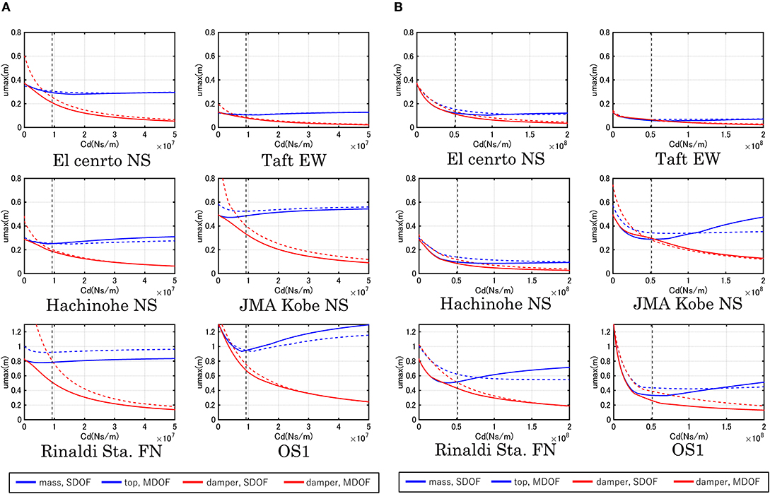
Figure 10. Simplified evaluation of maximum top displacement and maximum damper deformation. (A) Original Model and (B) Stiffer Model.
Figure 11A shows the maximum interstory drift angle for various damper damping coefficients for the Original Model and Figure 11B illustrates the corresponding one for the Stiffer Model. It can be seen that a large damper deformation is observed in the Stiffer Model. This means that the increase of stiffness of the strong-back core frame enhances the effectiveness of dampers. Furthermore, the optimal damper damping coefficient obtained for the multi impulse (Figure 8) reduces the maximum interstory drift angle of the main building most effectively. This phenomenon is significant for the input of OS1 (long-period, long-duration ground motion).
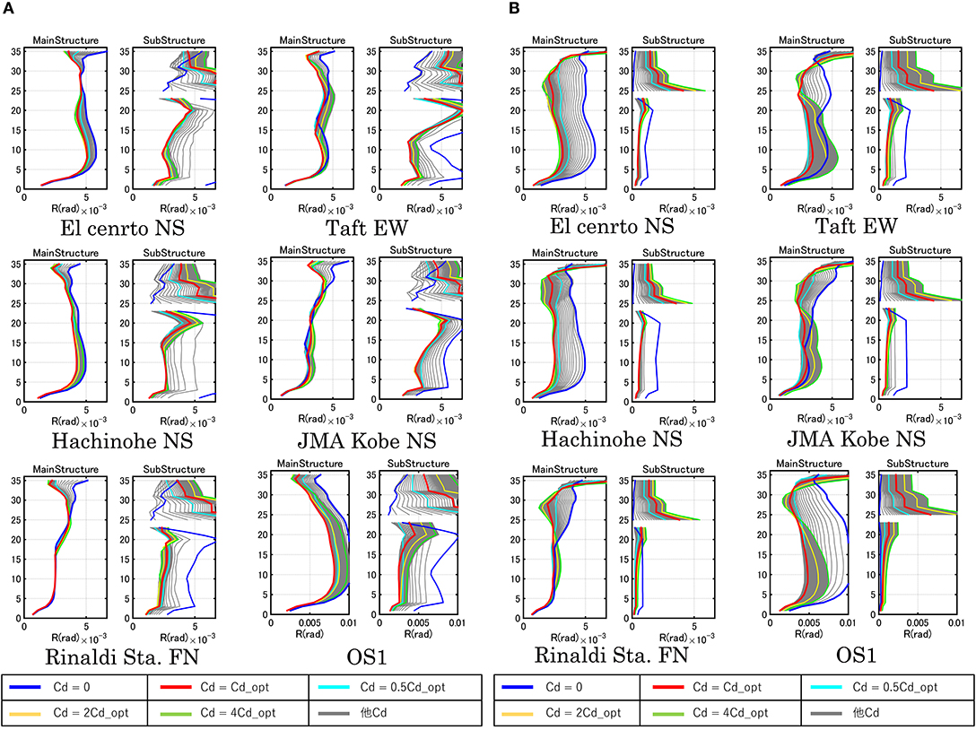
Figure 11. Maximum interstory drift angle for various damper levels. (A) Original Model and (B) Stiffer Model.
For the pulse-type ground motions (JMA Kobe NS, Rinaldi Sta. FN), the interstory drifts in the lower to middle stories are constant independent of the damper damping coefficients. The response reduction rates of the interstory drifts in the upper stories from the response of the model without damper are affected by the damper damping coefficients. In addition, such response reduction rates do not change much for the model with dampers larger than the optimal value. On the other hand, for the long-period, long-duration ground motion (OS1), the interstory drifts in the lower to middle stories are large and the response reduction rates of those are affected by damper quantities. The reduction rate is the largest for the optimal damper damping coefficient.
Earthquake Input Energy and Energy Transfer Function
The earthquake input energy is an important measure for evaluating the seismic performance of structures (Housner, 1959; Uang and Bertero, 1990; Takewaki, 2004a,b). The earthquake input energy to an elastic structure can be expressed in the frequency domain (Ordaz et al., 2003; Takewaki, 2004a,b). When the Fourier transform of the ground acceleration g(t) is denoted by g(ω), the total input energy to the MDOF model can be expressed by
where FMDOF(ω) is the energy transfer function defined by
In Equation (18), HD(ω), M1 denote the displacement transfer function vector of the MDOF model, the mass matrix of the MDOF model, and the influence vector of 1 s, respectively. The energy dissipated by the dampers can be expressed by
where is the energy transfer function for dampers defined by
Figure 12 shows the comparison of FMDOF(ω) (total system) and (damper system) for the damper damping coefficient . Since the areas of FMDOF(ω) and represent the total input energy and the damper consumption energy under the white noise-like input, the relation of the areas of FMDOF(ω) and indicates the energy dissipation performance of the dampers. The area of the energy transfer function is meaningful for the random input and the maximum value of the energy transfer function is important for the long-duration sine wave because the Fourier spectrum of the long-duration sine wave has a sharp peak and the maximum value of the energy transfer function correlates with such a peak. Properties for the area and the maximum value of the energy transfer function for increasing damper quantities are disclosed below.
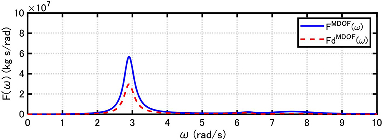
Figure 12. Energy transfer functions for total system and viscous damper installed at connection point between upper and lower strong-back core frames.
The total input energy to the equivalent SDOF model is:
where FSDOF(ω) is the energy transfer function for the SDOF model defined by
(ω) is derived by using the Maxwell model for the dashpot-spring model (frequency-dependent spring and damping coefficient in the Kelvin-Voigt model). The energy dissipated by the dampers in the SDOF model can be expressed by
where is the energy transfer function for the dampers in the SDOF model:
Figure 13A shows the area of the energy transfer function for the overall system and damper with respect to damper damping coefficient in the Original Model and the Stiffer Model. The area of the energy transfer function for the overall system is constant with respect to damper level regardless of the MDOF model or the SDOF model (Takewaki, 2004a,b). The difference between the MDOF model and the SDOF model is due to the difference of mass (the SDOF model disregards the mass of the lower strong-back core frame). It can also be observed that, while the SDOF model underestimates the area of the energy transfer function of the total input energy in the MDOF model, it overestimates the area of the energy transfer function as an index for energy dissipation performance of the dampers in the MDOF model. There also exists an optimal damper damping coefficient maximizing the area of the energy transfer function for the damper, i.e., the most effective damper damping coefficient. Those damper quantities are shown in Figure 13A. These optimal damper damping coefficients correspond well to the optimal ones, shown in Figure 8, obtained for the minimum top displacement for the multi impulse.
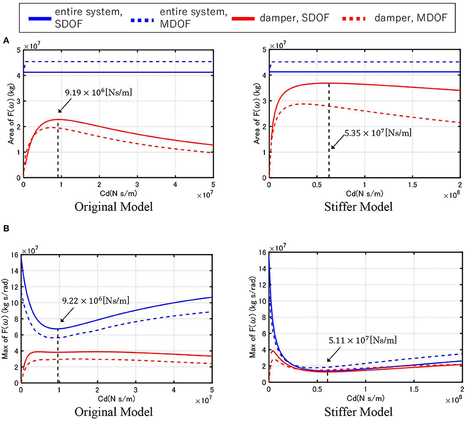
Figure 13. Area and maximum value of energy transfer function with respect to damper level. (A) Area of energy transfer function and (B) Maximum value of energy transfer function.
Figure 13B presents the maximum value of the energy transfer function with respect to the damper damping coefficient in the Original Model and the Stiffer Model. The SDOF model overestimates the maximum value of the energy transfer function for the total input energy and the damper energy consumption in the MDOF model in the Original Model. As the stiffness of strong-back core frame becomes larger, the energy consumption in the dampers governs the main part of the input energy.
Limitations of Proposed Control System and Simplification Method
To investigate the limitation of the proposed control system, further numerical computation was conducted for various parameters. It was clarified that (i) the stiffness ratio of strong-back core frames to the main frame has to possess a large value, (ii) the foundation of the main frame and the lower strong-back core frame has to have sufficient stiffness, (iii) the proposed system is not effective enough for so-called long-period pulse-type motions of large velocity amplitude. As the stiffness ratio of the strong-back core frames to the main frame and the stiffness of the foundation become larger, the effectiveness of the proposed control system is enhanced. The long-period pulse-type motions of large velocity amplitude over 2.0[m/s] as recorded at Kumamoto (Japan) in 2016 are critical and could cause extremely large interstory drifts in the lower stories of the main frame. It was confirmed that the introduction of interstory-type passive control systems into lower stories of the main frame in addition to the proposed control system is effective for such critical ground motions. It was also clarified that the proposed simplification method does not work well in the cases mentioned above.
Summaries and Conclusions
A new damper deformation concentration-type structural control system has been proposed for pulse-type and long-duration earthquake ground motions. Summaries and conclusions are as follows:
(1) A transformation method from an MDOF model into an SDOF model with a Maxwell-type spring-dashpot model was proposed, including a correction factor for compensating the difference in the damper behavior of both models. Then, the Maxwell-type spring-dashpot model was reduced to a Kelvin-Voigt model for a fixed frequency. The proposed control system and simplification method have some limitations: the stiffness ratio of the strong-back core frames to the main frame has to possess a large value, the foundation of the main frame and the lower strong-back core frame has to have sufficient stiffness, and the proposed system is not effective enough for so-called long-period pulse-type motions of large velocity amplitude over 2.0 [m/s].
(2) A simplified seismic response evaluation method to estimate the maximum deformation of the dampers was proposed for the reduced SDOF model, which was subjected to a resonant double impulse to represent near-fault pulse-type ground motions and a resonant multi impulse to represent long-duration, long-period ground motions. The closed-form expression of the response under the critical double impulse and the critical multi impulse provides an accurate prediction of the response for the corresponding one-cycle and long-duration sine waves. By using this method, the maximum top-story displacement of the main building and the maximum deformation of dampers can be estimated.
(3) The optimal damper damping coefficient minimizing the response of the main building can be obtained by changing the damper damping coefficient in the simplified response evaluation method.
(4) The energy transfer functions characterizing the earthquake energy input were derived for the MDOF model and the SDOF model. The area and the maximum value of the energy transfer functions were employed to evaluate the effectiveness and efficiency of the dampers. The area and the maximum value of the energy transfer functions of the SDOF model can approximate those in the MDOF model. The optimal damper damping coefficients derived from the maximization of the area of the energy transfer function correspond well to the optimal ones obtained for the minimum top displacement for the multi impulse.
(5) The response reduction performance from the model without dampers can be enhanced greatly by increasing the stiffness of the lower strong-back core frame attached to the foundation and the upper strong-back core frame hung from the top story stiff sub-assemblage of the main building.
Data Availability Statement
The datasets generated for this study are available on request to the corresponding author.
Author Contributions
AK formulated the problem, conducted the computation, and wrote the paper. TM conducted the computation and discussed the results. IT supervised the research and wrote the paper.
Funding
Part of the present work is supported by the Grant-in-Aid for Scientific Research (KAKENHI) of Japan Society for the Promotion of Science (Nos. 17K18922, 18H01584) and Takenaka Co.
Conflict of Interest
TM was employed by the company Takenaka Corporation.
The remaining authors declare that the research was conducted in the absence of any commercial or financial relationships that could be construed as a potential conflict of interest.
The authors declare that this study received funding from Takenaka Corporation. The funder was not involved in the study design, collection, analysis, interpretation of data, the writing of this article or the decision to submit it for publication.
Acknowledgments
This support was greatly appreciated. In addition, some ground motions used here were recorded by K-NET (National Research Institute for Earth Science and Disaster Resilience in Japan) and JMA (Japan Meteorological Agency).
References
Aydin, E., Boduroglu, M. H., and Guney, D. (2007). Optimal damper distribution for seismic rehabilitation of planar building structures. Eng. Struct. 29, 176–185. doi: 10.1016/j.engstruct.2006.04.016
Berg, G. V., and Thomaides, T. T. (1960). “Energy consumption by structures in strong-motion earthquakes,” in Proceedings of 2nd World Conferences on Earthquake Engineering (Tokyo; Kyoto), 681–696.
Christopoulos, C., and Filiatrault, A. (2006). Principle of Passive Supplemental Damping and Seismic Isolation. Pavia: IUSS Press.
Domenico, D. D., Ricciardi, G., and Takewaki, I. (2019). Design strategies of viscous dampers for seismic protection of building structures: a review. Soil Dyn. Earthquake. Eng. 118, 144–165. doi: 10.1016/j.soildyn.2018.12.024
Fukumoto, Y., and Takewaki, I. (2015). Critical demand of earthquake input energy to connected building structures. Earthq. Struct. 9, 1133–1152. doi: 10.12989/eas.2015.9.6.1133
Fukumoto, Y., and Takewaki, I. (2017). Dual control high-rise building for robuster earthquake performance. Front. Built Environ. 3:12. doi: 10.3389/fbuil.2017.00012
Garcia, D. L. (2001). A simple method for the design of optimal damper configurations in MDOF structures. Earthq. Spectra 17, 387–398. doi: 10.1193/1.1586180
Hall, J. F., Heaton, T. H., Halling, M. W., and Wald, D. J. (1995). Near-source ground motion and its effects on flexible buildings. Earthq. Spectra 11, 569–605. doi: 10.1193/1.1585828
Hanson, R. D., and Soong, T. T. (2001). Seismic Design With Supplemental Energy Dissipation Devices. Oakland, CA: Earthquake Engineering Research Institute.
Hayashi, K., Fujita, K., Tsuji, M., and Takewaki, I. (2018). A simple response evaluation method for base-isolation building-connection hybrid structural system under long-period and long-duration ground motion. Front. Built Environ. 4:2. doi: 10.3389/fbuil.2018.00002
Housner, G. W. (1959). Behavior of structures during earthquakes. J. Eng. Mech. Div. ASCE. 85, 109–129.
Housner, G. W. (1975). “Measures of severity of earthquake ground shaking,” in Proceedings of the US National Conferences on Earthquake Engineering,” (Ann Arbor, MI), 25–33.
Housner, G. W., Bergman, L. A., Caughey, T. K., Chassiakos, A. G., Claus, R. O., Masri, S. F., et al. (1997). Structural control: past, present, and future. J. Eng. Mech. ASCE. 123, 897–971. doi: 10.1061/(ASCE)0733-9399(1997)123:9(897)
Housner, G. W., and Jennings, P. C. (1975). “The capacity of extreme earthquake motions to damage structures,” in Structural and Geotechnical Mechanics: A Volume Honoring, eds N. M. Newmark, and W. J. Hall (Englewood Cliff, NJ: Prentice-Hall, 102–116.
Kojima, K., Saotome, Y., and Takewaki, I. (2017). Critical earthquake response of a SDOF elastic-perfectly plastic model with viscous damping under double impulse as a substitute of near-fault ground motion. J. Struct. Construct. Eng. 735, 643–652. doi: 10.1002/2475-8876.10019
Kojima, K., and Takewaki, I. (2015a). Critical earthquake response of elastic-plastic structures under near-fault ground motions (part 1: fling-step input), Front. Built Environ. 1:12. doi: 10.3389/fbuil.2015.00012
Kojima, K., and Takewaki, I. (2015b). Critical input and response of elastic-plastic structures under long-duration earthquake ground motions. Front. Built Environ. 1:1415. doi: 10.3389/fbuil.2015.00015
Kojima, K., and Takewaki, I. (2016). Closed-form critical earthquake response of elastic-plastic structures on compliant ground under near-fault ground motions. Front. Built Environ. 2:1. doi: 10.3389/fbuil.2015.00013
Lagaros, N. D., Plevris, V., and Mitropoulou, C. C. (2012). Design Optimization of Active and Passive Structural Control Systems. Hershey, PA: IGI Global. doi: 10.4018/978-1-4666-2029-2
Lai, J. W., and Mahin, S. A. (2015). Strongback system: a way to reduce damage concentration in steel-braced frames. J. Struct. Eng. ASCE. 141:04014223. doi: 10.1061/(ASCE)ST.1943-541X.0001198
Lavan, O., and Levy, R. (2005). Optimal design of supplemental viscous dampers for irregular shear-frames in the presence of yielding. Earthq. Eng. Struct. Dyn. 34, 889–907 doi: 10.1002/eqe.458
Leipholz, H. H. E. (1980). “Structural control,” in Proceedings of the International IUTAM Symposium on Structural Control, University of Waterloo (New York, NY: North-Holland Publishing Company).
Leipholz, H. H. E., and Abdel-Rohman, M. (1986). Control of Structures. Dordrecht: Martinus Nijhoff Publishers. doi: 10.1007/978-94-009-4402-2
Murase, M., Tsuji, M., and Takewaki, I. (2013). Smart passive control of buildings with higher redundancy and robustness using base-isolation and inter-connection. Earthq. Struct. 4, 649–670. doi: 10.12989/eas.2013.4.6.649
Ordaz, M., Huerta, B., and Reinoso, E. (2003). Exact computation of input-energy spectra from fourier amplitude spectra. Earthq. Eng. Struct. Dyn. 32, 597–605. doi: 10.1002/eqe.240
Palermo, M., Laghi, V., Gasparini, G., and Trombetti, T. (2018). Coupled response of frame structures connected to a strongback. J. Struct. Eng. ASCE. 144:04018148. doi: 10.1061/(ASCE)ST.1943-541X.0002134
Silvestri, S., and Trombetti, T. (2007). Physical and numerical approaches for the optimal insertion of seismic viscous dampers in shear-type structures. J. Earthquake Eng. 11, 787–828. doi: 10.1080/13632460601034155
Takewaki, I. (1997). Optimal damper placement for minimum transfer functions. Earthq. Eng. Struct. Dyn. 26, 1113–1124. doi: 10.3389/fbuil.2019.00004
Takewaki, I. (2004a). Frequency domain modal analysis of earthquake input energy to highly damped passive control structures. Earthquake Eng. Struct. Dyn. 33, 575–590. doi: 10.1002/eqe.361
Takewaki, I. (2004b). Bound of earthquake input energy. J. Struct. Eng. ASCE. 130, 1289–1297. doi: 10.1061/(ASCE)0733-9445(2004)130:9(1289)
Takewaki, I., Murakami, S., Fujita, K., Yoshitomi, S., and Tsuji, M. (2011). The 2011 off the Pacific coast of Tohoku earthquake and response of high-rise buildings under long-period ground motions. Soil Dyn. Earthq. Eng. 31, 1511–1528. doi: 10.1016/j.soildyn.2011.06.001
Takewaki, I. (2007). Critical Excitation Methods In Earthquake Engineering, 2nd Edn. Amsterdam: Elsevier. doi: 10.1016/B978-008045309-5/50013-3
Takewaki, I. (2009). Building Control With Passive Dampers: Optimal Performance-Based Design For Earthquakes. Singapore: John Wiley and Sons. doi: 10.1002/9780470824931
Tani, T., Maseki, R., and Takewaki, I. (2017). Innovative seismic response controlled system with shear wall and concentrated dampers in lower stories. Front. Built Environ. 3:57. doi: 10.3389/fbuil.2017.00057
Uang, C. M., and Bertero, V. V. (1990). Evaluation of seismic energy in structures. Earthquake Eng. Struct. Dyn. 19, 77–90. doi: 10.1002/eqe.4290190108
Whittle, J. K., Williams, M. S., Karavasilis, T. L., and Blakeborough, A. (2012). A comparison of viscous damper placement methods for improving seismic building design. J. Earthquake Eng. 16, 540–560. doi: 10.1080/13632469.2011.653864
Keywords: passive damper, viscous damper, building connection, double impulse, multi impulse, pulse-type motion, long-duration motion, input energy
Citation: Kawai A, Maeda T and Takewaki I (2020) Smart Seismic Control System for High-Rise Buildings Using Large-Stroke Viscous Dampers Through Connection to Strong-Back Core Frame. Front. Built Environ. 6:29. doi: 10.3389/fbuil.2020.00029
Received: 10 January 2020; Accepted: 28 February 2020;
Published: 19 March 2020.
Edited by:
Yoshikazu Araki, Nagoya University, JapanReviewed by:
Chia-Ming Chang, National Taiwan University, TaiwanMichele Palermo, University of Bologna, Italy
Barbara Gwynne Simpson, Oregon State University, United States
Copyright © 2020 Kawai, Maeda and Takewaki. This is an open-access article distributed under the terms of the Creative Commons Attribution License (CC BY). The use, distribution or reproduction in other forums is permitted, provided the original author(s) and the copyright owner(s) are credited and that the original publication in this journal is cited, in accordance with accepted academic practice. No use, distribution or reproduction is permitted which does not comply with these terms.
*Correspondence: Izuru Takewaki, dGFrZXdha2lAYXJjaGkua3lvdG8tdS5hYy5qcA==