 Francesco Nicassio
 Stefano Carrino
 Gennaro Scarselli
- Department of Engineering for Innovation, University of Salento, Lecce, Italy
A novel method based on Non-linear Lamb waves behavior and Local Defect Resonance (LDR) is proposed for locating and evaluating disbonds in Single-Lap Joints (SLJ) typically used in aerospace industry. The presence of damages/defects such as disbonds leads to the presence of sub- and super-harmonics components in the frequency response. The maximum acoustic wave-damage interaction is reached by particular excitation frequencies that enhance the Non-linear response causing LDR. The LDR frequency is experimentally evaluated through the appearance of a single subharmonic component in the frequency spectrum of signals received by piezoelectric transducer (PZT) bonded on the structure. The Non-linear properties of Lamb waves are exploited to make defects generate subharmonic waves at LDR frequency. An algorithm is implemented for damage/defect localization that is accurately obtained by knowing PZTs positions, Time of Flight (ToF) and propagation properties of subharmonics packet. Several disbonds with different dimensions are artificially reproduced on an aluminum SLJ: experimental and FE results show good accordance both in usual (single damage) and critical (multi-damage) scenario. The paper proposes a baseline-free method for the disbonds detection, characterization and localization in SLJs that uses the PZT signals without affecting adhesive interface, thus allowing for an active health monitoring.
Introduction
Over the past 20 years the airframe engineers and designers around the world have been studying alternatives to mechanical fastening in order to reach time and cost savings, higher fatigue, and corrosion resistance and crack propagation retardation (Mohammadi et al., 2015; Mohan Gift et al., 2016; Scarselli et al., 2017a). The welded and riveted joints alter the geometry causing inevitably changes in the stress and strain distribution and affecting the load capacity and long-term performances. Adhesive joints are used because they distribute the loads and stresses uniformly over the whole bonded area leading to a better vibration resistance. In addition, adhesive joints transmit the load from one adherend to another smoothly through the adhesive layer in the overlap region. However, several problems can affect the bond line of joints due to service degradation or manufacturing conditions. These could be classified into three groups (Ihn and Chang, 2008): the first group includes localized problems such as cracks, voids or delamination; the second group includes damages related to the adhesive mechanical properties (cohesive problem); the third one is related to adhesive problems and so to the strength of the adhesion between adhesive and adherend. In He (2014) and Sayman et al. (2013), it was demonstrated that the stress distributions of a single-lap adhesively bonded joint are affected by the boundary conditions and the stress concentrations are high only at interface free-ends (the central region of adhesive layer is almost stress-free). For these reasons, the free-ends of adhesive regions can be subjected to interfacial fracture due to either the normal or the shear stress or their combination exceeding the bond strength. The presence of disbonds in a SLJ is a critical aspect in automotive/aerospace industry, so a novel method was presented in this work for their detection, characterization, and position evaluation. Numerous techniques have been investigated to monitor and evaluate the structural health of SLJs bond. Digital image correlation and thermographic inspection methods can be used to evaluate the bond status: in Meola et al. (2004) pulse and modulated thermography with optical stimulation was used to study adhesive, welded and fastened joints; a laser interferometry technique combined with digital imaging processing (digital shearography) was used in Steinchen et al. (1998) to identify defects/damages both in small- and large-scale structures correlating them with strains anomalies. In Roth and Giurgiutiu (2017) an alternative method was used to monitor the state of adhesive bonds: electromechanical impedance spectroscopies were made by PZTs permanently bonded to the structure and disbonds were detected by the change in the mechanical impedance of the structure surrounding the damage. The A-, B-, and C-scan techniques allow to detect disbonds inside adhesive region by studying the propagation of a very high frequency signal (up to 50 MHz) transmitted to the structure (Vijaya Kumar et al., 2013). The X-ray techniques are less used on metal-to-metal bonded joints since the adhesive is much less dense than adherends (Adams and Drinkwater, 1999). However, the digital image techniques, impedance spectroscopy and all non-in-situ techniques can be used to inspect structures but they do not allow an active health monitoring. Fiber optic sensors have also been used for adhesive bond health monitoring that, integrated in the structure, can measure the shear stress at different positions, detect the presence of disbands, and evaluate their length (Sulejmani et al., 2014). The use of Ultrasonic Guided Waves (UGW), such as Lamb Waves, is very attractive for an efficient health monitoring system of large structures since they can propagate long distances in plates and shells with low attenuation (Staszewski, 2005; Kundu et al., 2019). In Carrino et al. (2019a) the disbond size of an aluminum SLJ was correlated with the wavelength of S0 Lamb mode attenuated by interference phenomena in the adhesive region: the approach is bidimensional and this limitation does not affect the relevance of the work but on the other hand does not allow the simulation of more complex 3D models. The present work aims to overcome this limitation with a 3D approach. In Santos and Perdigão (2005) and Scarselli et al. (2018) leaky Lamb waves were also used in a pitch-catch configuration for detecting and sizing defects or damages in bonded aluminum lap joints. The embedded sensors used in the present work, allow real-time structural monitoring and enhance the technique with immersion transducers presented in Santos and Perdigão (2005). In the recent years, adhesive bonding defects have been defined as kissing bond in which adherend and adhesive are in some way connected through a layer that exhibits an altered normal or shear stiffness (Yan et al., 2009). Several authors have numerically and experimentally shown that kissing-bond such as damage in SLJs can be detected using Non-linear Elastic Wave Spectroscopy (NEWS) methods as in Scarselli et al. (2017b) and Nicassio et al. (2019). These approaches are based on detection of acoustic Non-linearities due to Non-linear behavior of damages that is broadly defined as Contact Acoustic Non-linearity (CAN) (Drewry and Wilcox, 2014). The size of damage can be evaluated by measuring the level of the Non-linearities (sub- and super-harmonics) in the frequency spectra of waves propagating through it. In Yeum et al. (2014) a Lamb wave-based delamination detection technology that allows detection of delamination in a single wave propagation path without using prior baseline data was presented: if delamination exists along a wave propagation path, the first arrival antisymmetric (A0) mode is followed by other A0 modes reflected from the inside of the damage. The particular experimental set-up implies special dual PTZs and they make this technique more complicated and costly than the presented one. Sunarsa presented in Sunarsa et al. (2017) an experimental and analytical method for the in-situ detection of damage in adhesive-bonded structures. This method is fully non-contact, using air-coupled ultrasonic transducers (ACT) for ultrasonic wave generation and sensing: also in this case, the test set-up, with two ACTs, a sound blocker (to prevent leaking waves) and specific scan gap (to optimize the inspection area) makes this approach more complex in terms of practical point of view, respect to the proposed technique.
In the present work, a novel method based on CAN and Non-linear Lamb waves is proposed for locating disbonds in aluminum SLJ (see Figure 1).
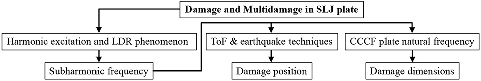
Figure 1. Schematic of the present research.
A set of four PZT transducers is bonded on the aluminum plates in order to transmit and receive signals propagating through adhesive region. The subharmonics generation due to harmonic excitation and LDR concept are used to detect disbond in bonded structures. Each PZT is excited one-by-one with a harmonic voltage and the LDR of damage is evaluated by the presence of a single-subharmonic component in the frequency spectra of signals received on the other PZTs (at each value of debonding there is a specific subharmonic frequency). Thus, the non-linear properties of Lamb waves are exploited to generate subharmonic wave packets (at LDR) that propagate from damage to PZTs. The damage position in the adhesive region is evaluated by an algorithm that exploits the ToF of subharmonic wave packets and the wave propagation velocity (calculated by dispersion curves). In the proposed work, the SLJ disbond is detailly simulated by Finite Elements (FE), geometrically characterized and accurately located via experimental campaigns with a baseline-free method without knowing the dynamic response of undamaged structure and by using embedded sensors that can allow long range inspections. The proposed method can be used for active Structural Health Monitoring (SHM) of SLJs typically utilized in automotive and aerospace field.
Materials and Methods
Materials
As in Carrino et al. (2019b), the novel method presented was implemented in this study in order to locate damages in an aluminum SLJ plate (see Figure 2). The specimen adopted for the experimental campaign was SLJ made of two aluminum plates 1.2 mm thick, 630 mm wide, 495 mm long (overlap equal to 50 mm, orange zone in Figure 2). The plates were bonded with an adhesive acrylic film (0.12 mm of nominal thickness). The properties for the aluminum alloy are: Young's modulus E = 72 GPa, density ρ = 2,770 kg/m3 and Poisson's ratio ν = 0.33. The acrylic adhesive had an elastic modulus = 3.69 GPa, density ρ = 1,300 kg/m3 and a Poisson's ratio = 0.3.
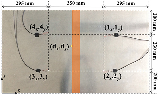
Figure 2. Experimental SLJ sample.
The yellow tag indicates the location of the three different artificial damages (5 × 5, 10 × 10, or 15 × 15 mm) by insertion of a thin Teflon patch between the adherend plate and the adhesive film. The sensors, 1–2–3–4, all alternatively used in exciting and receiving mode, were bonded onto the sample: these are disks with a diameter of 10 mm, 0.2 mm thick, with a resonant frequency of 10 MHz. The sensors are made of piezoelectric ceramic materials based on modified Lead Zirconate Titanate and Barium Titanate (material designation PIC255 that corresponds to 600 series of EN50324 European Standard). The four PZT sensors bonded on the structure have coordinates (ix, iy) with i = 1, 2, 3, 4 (as in Figure 2): Lamb wavelengths and reflections due to the joint boundaries were taken into account in order to achieve the optimal sensors placement. The artificial damage was placed on point of coordinates (dx, dy).
Analytical Approach
Hereinafter, for the sake of clearness and conciseness, the case in which the sensor 1 acts as exciter and 2, 3, and 4 as receivers is reported. In a simple way, the analytical approach with sensors 2, 3, and 4 as exciters can be extrapolated by the concerned subsection. During the propagation, Lamb waves strike the disbond at time t1d (from sensor 1 to damage d) and non-linear wave damage interaction takes place producing harmonics generation due to contact non-linearity. These sub- and super-harmonics propagate in all directions from the damage. In this way, the signals received by 2, 3, and 4 contain the direct wave packet generated by 1, a group of harmonics produced by the contact Non-linearity and the reflections due to the joint boundaries. In particular, the harmonic packets contain frequency and time information about the presence of disbond. The ToF of subharmonic packets received by 2, 3, and 4 are denoted with t2, t3 and t4, respectively. It can be written that:
with tdi the time taken by the subharmonic packet to reach the ith receiver sensor from the damage d. For each pair of sensors i and j, it can be also written by using (1):
where Δtij is the difference of arrival times of the subharmonic from the damage to the sensors i and j, respectively. The group velocities of the fundamental and subharmonic packet are defined with and . The distances between the defect and exciting (r1d) or receiving (rdi) sensors are defined and calculated by the following equations:
Δrij can be written by using (3) as a function of subharmonics ToFs (in terms of Δtij):
In addition, Δrij can be also evaluated by simply geometric considerations for each plate point of coordinates (x, y):
In conclusion, at each point of the SLJ corresponds to specific coordinates that can satisfy (x = dx, y = dy) or not (x ≠ dx, y ≠ dy) the system of Equations (4) and (5), in which , ix and iy are specimen known terms and Δtij is experimental data. A Gaussian distribution with mean is used to obtain a probability density function Pij = Pij (x,y) (with variance equal to 1/2π) and to map the space of points satisfying the (4, 5): in this way measurement uncertainties are taken into account.
In (6), can be experimentally evaluated and the only unknowns in are x and y. The probability density function (with sensor 1 as exciter) is evaluated according to the following equation:
The Equation (7) gives an estimation of damage locations as those points where the values P(x,y) get close to 1. In the same way, the probability density functions (with sensors 2, 3, and 4 as exciters) are evaluated and the total probability density function is estimated by:
The method is baseline free since it is not based on data from the pristine SLJ.
FE Model
The FE model of the SLJ tested sample was created in Ansys Workbench (ANSYS Product Launcher, 2019) where coupled field elements were used to study the PZTs acquisition system bonded onto the plates. Coupled analysis was performed to understand the generation of subharmonics associated with Lamb waves due to partial debonding of the overlap zone. The investigated SLJ consisted of two plates geometrically represented in Figure 2. The adhesive layer was split into an active region where the plates were actually joined and another region where the Teflon patch avoided the adhesion. The PZT sensors were modeled as disks of nominal diameter and thickness of 10 and 0.2 mm, respectively, and were located as in Figure 2. A 3D model was developed by using Design Modeler (DM).
The aluminum plate was discretized by shell elements SHELL181 suitable for analyses of moderately-thick structures (they have four-nodes with six degrees of freedom at each node). PZT disks were meshed by SOLID226 elements supporting piezoelectric physics combination (they have 20 nodes with up to five degrees of freedom per node). The CONTA174 elements were used to mesh the contact between PZT sensors and structure (the element has the same geometric characteristics as the solid or shell element face with which it is connected), while TARGE170 surface-to-surface contact elements were used to model the adhesive/plate and contacts, describing the boundary of a deformable body. The undamaged part of the adhesive joint and the PZTs/plate interface were set to bonded type so no sliding or separation was allowed: the Multi-Point Constraint (MPC) algorithm was used to formulate mathematically the behavior of these contacts. The debonded region is characterized by two surfaces that are free to separate and move away from each other causing structural stiffness changes and, consequently, non-linearities on global response. So, the debonded region was modeled by a frictionless contact. The typical element size was set to λe/40 where λe is the wavelength propagating in an aluminum plate excited by a frequency fe. The splitting surface in the geometry creation allowed to obtain similar mesh near to the PZT locations so it was possible to merge node at the interface for a better transmission of the excitation. Free boundary condition was simulated because it better represented the experimental set-up.
Transient Structural (TS) analyses were carried out in order to evaluate the Non-linear signals by exciting PZTs one at time:
• The harmonic excitations were simulated with a timestep equal to 1/20fe where fe is the harmonic frequency; sensors were loaded by the same experimental harmonic signal, specified as a function in Workbench.
• The experimental toneburst was imported in Workbench and applied on sensors in order to simulate the fundamental Lamb waves. In settings, two steps were specified: the time length of the first equals the length of toneburst and those of the second one was fixed to 600 μs.
The signals numerically detected on the receivers were then post-processed in MATLAB by using the Fast Fourier Transform (FFT) and Short Time Fourier Transform (STFT) in order to obtain the frequency spectra.
Results
During the first round of experimental tests, the different artificial damages (5 × 5, 10 × 10, and 15 × 15 mm) were placed as in Figure 2. By varying exciting frequencies fe from 1 kHz to 1 MHz with 1 kHz increment, a pure harmonic voltage was sent by the signal generator TG5012A of Aim & Thurlby Thandar Instrument to each sensor (in exciting mode) and acquired by the remaining sensors in receiving mode.
Exciting frequencies bigger than 1 MHz reveal small damages with a no dangerous characteristic length respect to the geometry of the considered SLJ, while frequencies smaller than 1 kHz were not taken into account since they excite big damages look far from practical interest. So, by tuning the exciting frequency, the spectral response provided SLJ Non-linear behavior (e.g., FFT in Figure 3 with exciting sensor 1 and receiving sensors 2–3–4):
• Damage 15 × 15, at fe = 62 kHz, with appeared a dominant subharmonic at fD = 30 kHz ≈ fe /2.
• Damage 10 × 10, at fe = 133 kHz, with appeared a dominant subharmonic at fD = 66 kHz ≈ fe /2.
• Damage 5 × 5, at fe = 398 kHz, with appeared a dominant subharmonic at fD = 198 kHz ≈ fe /2.
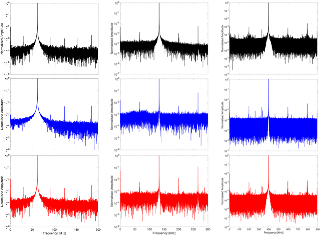
Figure 3. Spectral response [excitation in 1 with a 62 kHz (LEFT), 133 kHz (CENTER), and 398 kHz (RIGHT) pure sine and acquisition with sensors 2 in black, 3 in blue, and 4 in red].
The technical literature [as studied in Scarselli et al. (2018)] reports the appearance of subharmonics and higher order harmonics in the SLJ structural response as a consequence of a disbond in the overlapped zone [LDR phenomenon (Solodov et al., 2011, 2013; Solodov, 2014)].
As reported in Carrino et al. (2019c), the disbonds were experimentally manufactured and numerically modeled with artificial defects, in order to understand how the defect dimensions influence the behavior of a SLJ with defect when harmonic steady and transient waves propagate through the structure.
The defect (disbonded adherend) behaves like a rectangular Kirchhoff plate (a × b with thickness t), with one edge a being free and the other three fully clamped (CCCF plate). The interaction (contact) between the damage with the main structure causes the debonded area to vibrate (hence exciting the first n vibrational modes that contribute to the response of the disbond). The number n depends on the actual frequency content of the impulse. In this scenario, with a simplification of the actual structure, without loss of generality, the damage (CCCF rectangular plate) “only vibrates” at the frequency f1 (Morozov and Lopatin, 2010):
where E, ν, and ρ are the mechanical properties of the SLJ adherend and λ is a dimensionless material/geometrical parameter. So, when a single, pronounced subharmonic appears in the response frequency spectrum of the entire system, from Equation (9), the disbond dimensions a and b can be strictly related [see Figure 4 in which there is a good correlation between the first natural frequencies of a FE plate (red circles) and the function in Equation (9)].
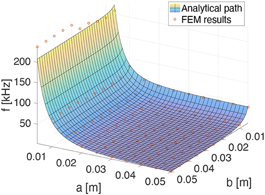
Figure 4. Fundamental frequencies (function of a and b) of a CCCF plates: FE results vs. Equation (9).
It follows from Figure 4 that the Aspect Ratio (AR = a/b) strongly affects the frequency values, but the only single dominant subharmonic frequency fD cannot be related univocally to dimensions a and b. After some rearrangements in Equation (9), it was possible evaluate (in Figure 5) the free edge dimension per each subharmonic appearance in a reasonable AR range:
• Disbond ARs smaller than 0.5 were not taken into account since they look far from practical interest respect to the geometry of the considered SLJ (the maximum interfacial shear stress takes place at the boundary of bonded region and as soon as the adhesive failure starts, the progressive failure follows b direction).
• Disbond ARs bigger than 1.5 were not taken into account since they are too deep and the failure should already have occurred.
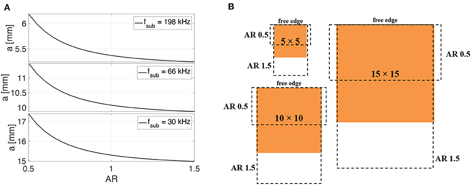
Figure 5. (A) Free edge dimension vs. AR and (B) possible damage areas per each subharmonic frequency.
In all cases, the free edge dimension falls in a small range of values although AR varies significantly. Referring to the experimental results (AR = 1), in Table 1 values of damage dimensions and relative subharmonic frequencies are reported (with good agreement between numerical results and experimental data).
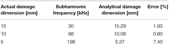
Table 1. Actual vs. analytical damage dimensions.
Once known the excitation frequency values (and the relative damage dimensions) for which one single dominant subharmonic appears, in the second round of the experimental campaign, a 5 peaks toneburst was used in order to evaluate the ToF of exciting and receiving signals (S0, A0, and their subharmonic wave packets): the purpose of this second step is to locate disbonds in the SLJ. During this experimental campaign, through the oscilloscope Serie 3000 PicoScope (in Single Trigger mode control), the scope monitored the incoming signal and waited for the voltage to rise above a given threshold (variable for each damage); then, it caused the scope to capture and display just the first received waveforms on the receivers. As an example, for the experiment with damage =10 × 10 mm and sensor 1 in exciting mode, the trigger time was at 270.0 μs. The S0 and A0 wave packets reached the sensor 2 after 45.6 and 114.9 μs, respectively. Thus, the experimental group velocities at 133 kHz were estimated by the ratio between these ToFs and the sensors distance (230 mm as in Figure 2): the S0 packet propagated at 5044 m/s while the A0 packet at 2002 m/s, in a good agreement with analytical dispersion curves (Roth and Giurgiutiu, 2017). The resulting subharmonics packets traveled in all directions from the damage reaching the receiver sensors. In this study, the subharmonic A0 wave packets were chosen to inspect the structure since it, inducing out-of-plane motions, promoted much higher non-linearities than those caused by S0 mode. An example of STFT of experimental signal (damage 10 × 10 mm and exciting sensor 1) is reported in Figure 6 (for each subfigure: TOP, received packets and BOTTOM, subharmonic packets): A0–S0 is the packet produced by the S0 exciting packet, A0–A0 is the packet produced by the A0 exciting packet.
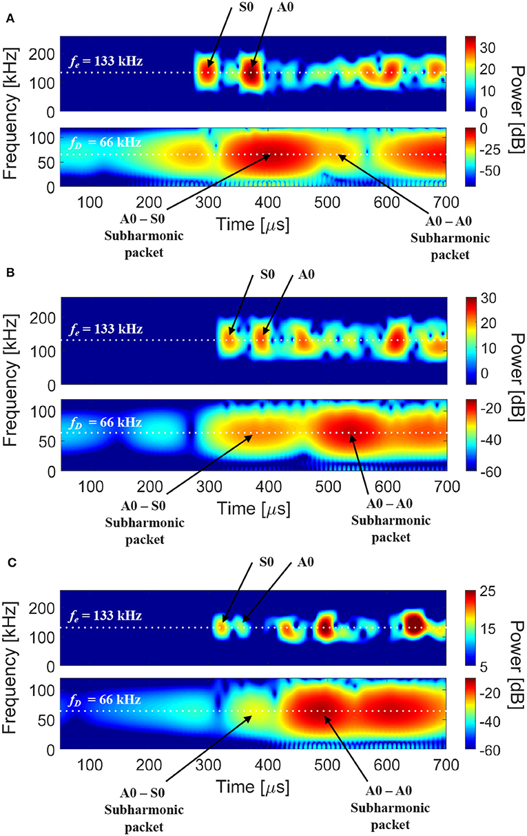
Figure 6. STFT of signal received by sensor 2 (A), 3 (B), and 4 (C): received packets at 133 kHz (exciting frequency fe) and subharmonic packets at 66 kHz (damage resonant frequency fD).
In Table 2, values of ToFs for each damage are reported: these experimental data (ToFs values in Table 2 were obtained by gathering subharmonic information from Figure 6) were post-processed in order to estimate Δtij of Equation (6) and hence the total probability function that gives an estimation of damage locations.
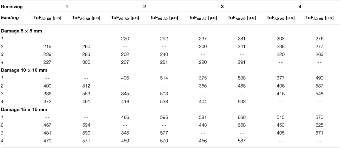
Table 2. ToF for different damages and exciting sensors.
As the earthquake epicenter, the damage location was found by the triangulation technique.
This localization method is based on geometric properties. Each receiving sensor gathered information on the subharmonic packet, in terms of ToF and hence the distance between itself and the subharmonic source (SLJ damage). Next, branch hyperbolae [see Equation (4)] related to focuses represented by i and j sensors were built by using the calculated distances (dotted white line in Figure 7). The intersection of these branches was the estimated position of disbond. To make this algorithm more accurate, the damage estimation was repeated for each exciting sensor and all results were combined into one unique LDR source. In Figure 8 the total probability functions per each damage are reported: in each row the FE and experimental cases are represented, i.e., the relative numerical results were validated through experimental measurements.
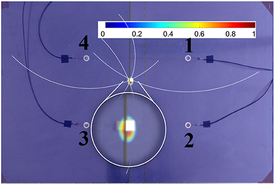
Figure 7. Triangulation method for locating the SLJ.
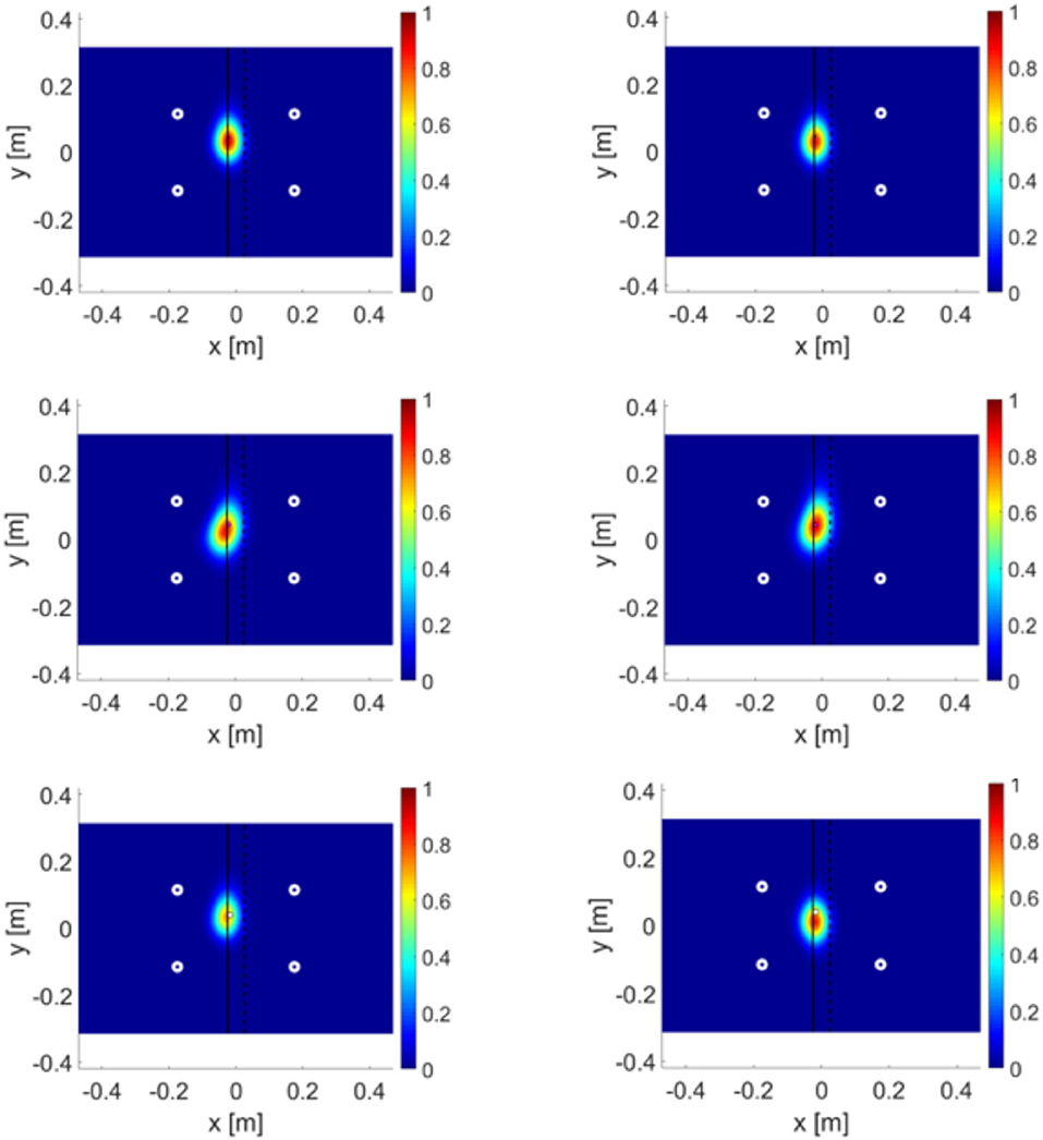
Figure 8. LEFT experimental results, RIGHT FEM results; TOP (damage 5 × 5 mm), CENTER (damage 10 × 10 mm), BOTTOM (damage 15 × 15 mm).
This technique appears detailed and reliable and provides a baseline-free detection tool for the identification of a SLJ disbond. Eventually, in order to prove the method applicability, consistency and robustness in critical scenario, a sample with 3 different damages (in the overlap zone) was tested. From top to bottom on Figure 9, the Teflon patches dimensions were 5 × 5 mm, 15 × 15 mm, and 10 × 10 mm. A frequency sweep (by using each sensor) excited the testing structure in order to monitor the dynamical response at the adhesive zone to find subharmonics induced by LDR. Three exciting frequencies fe (62, 133, and 401 kHz) caused three different single dominant subharmonics fD ≈ fe/2 in the structural response.
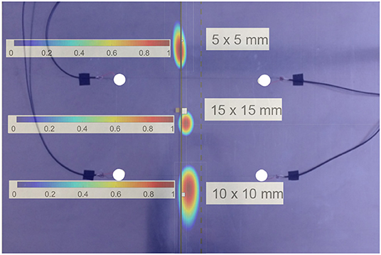
Figure 9. Multidamage SLJ sample and localization of damages by using the triangulation algorithm.
Successively, the triangulation algorithm was applied and the Figure 9 shows the good accuracy of the proposed method.
Conclusions
Damaged SLJ plates were tested for SHM purposes. Artificial defects were introduced in the specimens, debonding the adhesive layer from the upper adherend. The experimental procedure is made of two consecutive steps: the first one consisting in a harmonic loading aimed at exciting the artificial defects in order to promote LDR conditions; the second one based on the generation of a transient signal traveling through the adhesive layer. The interaction mechanism between the waves traveling through the investigated specimens was numerically modeled via FE. The analytical closed-form solution providing estimate damage dimensions by using the first natural frequency of a CCCF plate. The two combined experimental activities showed that, for each damage, there is one excitation frequency for which subharmonic packets occurred. By knowing the ToF of the subharmonic packet and its propagation velocity, it was possible to evaluate the distance between the receiving sensor and the damage. The triangulation technique was implemented in order to develop a consistent and robust SHM method for multidamaged adhesives in a SLJ. In addition, the accurate results of this work will be starting points of future works by using more complex and/or composite structures.
Data Availability Statement
All datasets generated for this study are included in the article/supplementary material.
Author Contributions
GS: conceptualization, writing—review and editing, supervision, project administration, and resources. GS, SC, and FN: methodology and visualization. SC: software. FN: validation. SC and FN: formal analysis, investigation, data curation, and writing—original draft preparation.
Conflict of Interest
The authors declare that the research was conducted in the absence of any commercial or financial relationships that could be construed as a potential conflict of interest.
Acknowledgments
A preliminary version of the method was developed and presented by the authors at the IEEE International Workshop on Metrology for AeroSpace, MetroAeroSpace 2019 [see Reference (Carrino et al., 2019b)].
References
Adams, R. D., and Drinkwater, B. W. (1999). Non-destructive testing of adhesively-bonded joints. Int. J. Mater. Prod. Technol. 14, 385–398. doi: 10.1016/S0963-8695(96)00050-3
ANSYS Product Launcher. (2019). ANSYS Product Launcher. Available online at: https://ansyshelp.ansys.com
Carrino, S., Nicassio, F., and Scarselli, G. (2019b). “An innovative method based on nonlinear lamb waves for locating disbonds in Single-Lap joints,” in 2019 IEEE International Workshop on Metrology for AeroSpace, MetroAeroSpace 2019 - Proceedings (IEEE) (Turin), 187–191. doi: 10.1109/MetroAeroSpace.2019.8869582
Carrino, S., Nicassio, F., and Scarselli, G. (2019c). Subharmonics and beating: a new approach to local defect resonance for bonded single lap joints. J. Sound Vib. 456, 289–305. doi: 10.1016/j.jsv.2019.05.039
Carrino, S., Nicassio, F., Scarselli, G., and Vitolo, R. (2019a). Finite difference model of wave motion for structural health monitoring of single lap joints. Int. J. Solids Struct. 161, 219–227. doi: 10.1016/j.ijsolstr.2018.11.019
Drewry, M. A., and Wilcox, P. D. (2014). One-dimensional time-domain finite-element modelling of nonlinear wave propagation for non-destructive evaluation. NDT E Int. 61, 45–52. doi: 10.1016/j.ndteint.2013.09.006
He, X. (2014). Influence of boundary conditions on stress distributions in a single-lap adhesively bonded joint. Int. J. Adhes. Adhes. 53, 34–43. doi: 10.1016/j.ijadhadh.2014.01.009
Ihn, J. B., and Chang, F. K. (2008). Pitch-catch active sensing methods in structural health monitoring for aircraft structures. Struct. Heal. Monit. 7, 5–19. doi: 10.1177/1475921707081979
Kundu, T., Eiras, J. N., Li, W., Liu, P., Sohn, H., and Pay,á, J. (2019). “Fundamentals of nonlinear acoustical techniques and sideband peak count,” in Nonlinear Ultrasonic and Vibro-Acoustical Techniques for Nondestructive Evaluation, ed. T. Kundu (Basel: Springer International Publishing), 1–88. doi: 10.1007/978-3-319-94476-0_1
Meola, C., Carlomagno, G. M., Squillace, A., and Giorleo, G. (2004). The use of infrared thermography for nondestructive evaluation of joints. Infrared Phys. Technol. 46, 93–99. doi: 10.1016/j.infrared.2004.03.013
Mohammadi, J., Behnamian, Y., Mostafaei, A., Izadi, H., Saeid, T., Kokabi, A. H., et al. (2015). Friction stir welding joint of dissimilar materials between AZ31B magnesium and 6061 aluminum alloys: microstructure studies and mechanical characterizations. Mater. Charact. 101, 189–207. doi: 10.1016/j.matchar.2015.01.008
Mohan Gift, M. D., Selvakumar, J., and John Alexis, S. (2016). Analysis of crack propagation in an adhesive joint. Int. J. Chem. Sci. 14, 485–496.
Morozov, E. V., and Lopatin, A. V. (2010). Fundamental frequency of the CCCF composite sandwich plate. Compos. Struct. 92, 2747–2757. doi: 10.1016/j.compstruct.2010.04.002
Nicassio, F., Carrino, S., and Scarselli, G. (2019). Elastic waves interference for the analysis of disbonds in single lap joints. Mech. Syst. Signal Process. 128, 340–351. doi: 10.1016/j.ymssp.2019.04.011
Roth, W., and Giurgiutiu, V. (2017). Structural health monitoring of an adhesive disbond through electromechanical impedance spectroscopy. Int. J. Adhes. Adhes. 73, 109–117. doi: 10.1016/j.ijadhadh.2016.11.008
Santos, M., and Perdigão, J. (2005). Leaky lamb waves for the detection and sizing of defects in bonded aluminium lap joints. NDT E Int. 38, 561–568. doi: 10.1016/j.ndteint.2005.02.004
Sayman, O., Ozen, M., and Korkmaz, B. (2013). Elasto-plastic stress distributions in adhesively bonded double lap joints. Mater. Des. 45, 31–35. doi: 10.1016/j.matdes.2012.09.005
Scarselli, G., Ciampa, F., Nicassio, F., and Meo, M. (2017b). Non-linear methods based on ultrasonic waves to analyse disbonds in single lap joints. Proc. Inst. Mech. Eng. Part C J. Mech. Eng. Sci. 231, 3066–3076. doi: 10.1177/0954406217704222
Scarselli, G., Corcione, C., Nicassio, F., and Maffezzoli, A. (2017a). Adhesive joints with improved mechanical properties for aerospace applications. Int. J. Adhes. Adhes. 75, 174–180. doi: 10.1016/j.ijadhadh.2017.03.012
Scarselli, G., Nicassio, F., and Carrino, S. (2018). “SHM of aerospace bonded structures with improved techniques based on NEWS,” in Health Monitoring of Structural and Biological Systems XII, ed. T. Kundu (Denver, CO: SPIE), 96. doi: 10.1117/12.2300350
Solodov, I. (2014). Resonant acoustic nonlinearity of defects for highly-efficient nonlinear NDE. J. Nondestruct. Eval. 33, 252–262. doi: 10.1007/s10921-014-0229-9
Solodov, I., Bai, J., Bekgulyan, S., and Busse, G. (2011). A local defect resonance to enhance acoustic wave-defect interaction in ultrasonic nondestructive evaluation. Appl. Phys. Lett. 99:211911. doi: 10.1063/1.3663872
Solodov, I., Bai, J., and Busse, G. (2013). Resonant ultrasound spectroscopy of defects: case study of flat-bottomed holes. J. Appl. Phys. 113:223512. doi: 10.1063/1.4810926
Staszewski, W. J. (2005). Ultrasonic/guided waves for structural health monitoring. Key Eng. Mater. 293–294, 49–60. doi: 10.4028/www.scientific.net/kem.293-294.49
Steinchen, W., Yang, L., Kupfer, G., and Mäckel, P. (1998). Non-destructive testing of aerospace composite materials using digital shearography. Proc. Inst. Mech. Eng. Part G J. Aerosp. Eng. 212, 21–30. doi: 10.1243/0954410981532108
Sulejmani, S., Sonnenfeld, C., Geernaert, T., Luyckx, G., Mergo, P., Urbanczyk, W., et al. (2014). Disbond monitoring in adhesive joints using shear stress optical fiber sensors. Smart Mater. Struct. 23:075006. doi: 10.1088/0964-1726/23/7/075006
Sunarsa, T. Y., Aryan, P., Jeon, I., Park, B., Liu, P., and Sohn, H. (2017). A reference-free and non-contact method for detecting and imaging damage in adhesive-bonded structures using air-coupled ultrasonic transducers. Materials. 10:1402. doi: 10.3390/ma10121402
Vijaya Kumar, R. L., Bhat, M. R., and Murthy, C. R. L. (2013). Evaluation of kissing bond in composite adhesive lap joints using digital image correlation: Preliminary studies. Int. J. Adhes. Adhes. 42, 60–68. doi: 10.1016/j.ijadhadh.2013.01.004
Yan, D., Drinkwater, B. W., and Neild, S. A. (2009). Measurement of the ultrasonic nonlinearity of kissing bonds in adhesive joints. NDT E Int. 42, 459–466. doi: 10.1016/j.ndteint.2009.02.002
Keywords: ultrasonics, non-linearity, disbond, LDR, lamb waves, SLJ
Citation: Nicassio F, Carrino S and Scarselli G (2020) Non-linear Lamb Waves for Locating Defects in Single-Lap Joints. Front. Built Environ. 6:45. doi: 10.3389/fbuil.2020.00045
Received: 12 December 2019; Accepted: 24 March 2020;
Published: 15 April 2020.
Edited by:
Eleni N. Chatzi, ETH Zürich, SwitzerlandReviewed by:
Ning Hu, Chongqing University, ChinaRohan Nandkishor Soman, Institute of Fluid Flow Machinery (PAN), Poland
Copyright © 2020 Nicassio, Carrino and Scarselli. This is an open-access article distributed under the terms of the Creative Commons Attribution License (CC BY). The use, distribution or reproduction in other forums is permitted, provided the original author(s) and the copyright owner(s) are credited and that the original publication in this journal is cited, in accordance with accepted academic practice. No use, distribution or reproduction is permitted which does not comply with these terms.
*Correspondence: Francesco Nicassio, ZnJhbmNlc2NvLm5pY2Fzc2lvQHVuaXNhbGVudG8uaXQ=