 Mateusz Kaluza
 Paweł Komorowski2
- 1Faculty of Physics, Warsaw University of Technology, Warsaw, Poland
- 2Institute of Optoelectronics, Military University of Technology, Warsaw, Poland
This study presents the novel optical passive components for spatial frequency division demultiplexing of terahertz (THz) radiation. Four different diffractive optical elements (DOEs) were designed as the combination of phase kinoform lenses and phase blazed diffraction gratings. The designed structures were verified in numerical simulations and they showed the promising results. Subsequently, they were manufactured using fused deposition modeling (FDM) 3D printing technology from highly transparent cyclic olefin copolymer (COC). The manufactured structures were examined in the experimental setup. The results matched numerical simulations. Thus, eight frequencies in the range from 150 GHz to 220 GHz every 10 GHz were spatially separated. The novel design solution guaranteed 63% higher relative efficiency compared to the reference DOE. The presented study can be suitable as the application for 6G technology telecommunication systems as the spatial frequency division demultiplexing component for the THz radiation band.
1 Introduction
The rapid development of terahertz (THz) optics has been evident in many fields of science and industry. In recent years, THz optics has found the applications in non-destructive testing (Fan et al., 2017; Zhong, 2018; Tao et al., 2020), detection of toxic/explosive chemical compounds (Massaouti et al., 2013; Trofimov and Varentsova, 2016; Yang et al., 2018), and security (Tribe et al., 2004; Federici et al., 2005; Palka et al., 2012; Knipper et al., 2015; Tzydynzhapov et al., 2020). At the same time, in the near future, THz optics can also be applied in free space telecommunication systems (Piesiewicz et al., 2008; Nagatsuma et al., 2013; Ducournau et al., 2014; O’Hara et al., 2019; Komorowski et al., 2021b; Chen et al., 2022), especially in the 6G telecommunication technology (Kleine-Ostmann and Nagatsuma, 2011; Akyildiz et al., 2014; IEEE, 2017; Faisal et al., 2020; Jiang et al., 2021; Chaccour et al., 2022). Nowadays, the end-user data distribution provided by Wi-Fi technology where short-range wireless telecommunication is required is one of the hurdles of data transmission systems. The reason for it is the fact that the capacity of Wi-Fi links has reached its limits and cannot meet the needs of rapidly developing telecommunication technology.
The application of the solutions based on the THz radiation band provides higher radiation frequencies, thus increasing the data transfer ratio and improving the performance of end-user telecommunication systems. The use of THz frequencies for telecommunication has a number of advantages. THz frequencies can address spectrum deficiency problems and significantly improve the capacity of current wireless systems. This creates the opportunity for various applications that might take advantage of wireless, free space THz range signal distribution. There are many examples of promising applications of 6G technologies such as the Tbps Wireless Local Area Network (WLAN), wireless personal area networks (WPAN) systems, Tbps integrated access backhaul (IAB) wireless networks, Tbps Internet-of-Things (IoT) wireless networks in data centers or THz space communication systems (Mehdi et al., 2018; Petrov et al., 2018; Chen et al., 2019; Han et al., 2019; Liu et al., 2020). However, as the THz spectrum can resolve some telecommunication problems, most applications require multiplexing of THz radiation to achieve a proper data transfer within a network system.
The application of multiple-input-multiple-output (MIMO) systems is a well-known method for the multiplication of the capacity of telecommunication system links. The task of the MIMO system is to redirect the beams from multiple antennas to multiple detectors. For this purpose, one of the possible solutions is to build a system where a multiple-input-single-output (MISO) component is used to couple THz radiation from different antennas into a single optical channel (multiplexing) where radiation propagates in free space. Subsequently, a single-input-multiple-output (SIMO) component is responsible for the separation of optical signals and redirecting them to the detectors (demultiplexing).
This work focuses on the second functionality which is the demultiplexing of the THz radiation. The spatial frequency division (de)multiplexing is the applied method to perform the THz SIMO component functionality, realized by a single diffractive optical element (DOE). Such an application guaranteed spatial separation of THz beams upcoming from a single free space optical channel according to applied frequencies.
Using the appropriate optical elements capable of the THz beam shaping in a desired way is crucial in the implementation of the THz SIMO component working in the transmission regime (Mínguez-Vega et al., 2008; Surma et al., 2018; Machado et al., 2019; Siemion, 2019; He et al., 2020; Siemion, 2020; Veli et al., 2021). Many passive optical elements for the THz spectral range, such as refractive lenses, are relatively bulky and thick, especially for large diameters and short focal lengths. Therefore, the material’s optical properties and the structure’s thickness introduce unnecessary radiation attenuation during its propagation within the structure. Bulky refractive lenses can be replaced with thin diffractive structures providing even more complex phase distribution and allowing for more accurate beam shaping dependent on applicational needs (Monnai et al., 2013; Liu et al., 2016; Luo et al., 2019; Siemion et al., 2020; Komorowski and Siemion, 2022; Surma et al., 2022).
The cost of production of THz optical elements is usually high as a result of the limited number of materials showing suitable optical properties in the THz radiation range. Currently, research is being conducted on new materials for the production of THz optics (Cunningham et al., 2011; Siemion et al., 2012; Han et al., 2013; Sahin et al., 2019; Siemion, 2020; Kaluza et al., 2022). Promising results for polymer materials provide the opportunity to replace Teflon, the most widely used material in the fabrication of THz optics, which is costly considering the low-scale production of optical components (Wietzke et al., 2011; Fedulova et al., 2012; Sahin et al., 2019; Kaluza et al., 2022). It has to be highlighted that additive manufacturing technologies apply different forms of various polymer materials in the manufacturing process, e.g., fused deposition modeling (FDM) uses filament wires or selective laser sintering (SLS) requires polymer powers. Moreover, 3D printing techniques provide benefits in the manufacturing process, such as fast prototyping, cheap and good quality production of complex printing models, and access to various polymer and composite materials not available in other manufacturing technologies (Ngo et al., 2018; Shahrubudin et al., 2019; Sun and Hu, 2019).
This work presents the novel optical structures for spatial demultiplexing of THz radiation according to the frequency used in the optical system. The structures were designed as the combination of different types of DOEs, and resulting in obtaining new unique structures. The numerical simulations were performed and the corresponding SIMO structures were manufactured using FDM 3D printing. Cyclic olefin copolymer (COC), previously examined with the THz time-domain spectroscopy (TDS) (Kaluza et al., 2022), was chosen as the best material for manufacturing SIMO structures. Subsequently, manufactured SIMO structures were verified in an experimental setup considering narrow-band input THz signals.
This work is the continuation of the previous studies (Komorowski et al., 2021a; Komorowski et al., 2021b) on the issue of frequency multiplexing of THz waves. In this paper, various solutions for the reduction of unwanted orders of diffraction are proposed, modeled, manufactured, and experimentally verified.
2 The design
The combination of two different DOEs was used during the design process of the demultiplexing THz SIMO structures. The first component of SIMO structures was a flat phase kinoform diffractive lens, which focuses incoming radiation in a single focal spot and guarantees a high diffraction efficiency of up to 100% (Buralli et al., 1989; Kress and Meyrueis, 2000). The shape of the first component (phase kinoform lens) was designed according to the following formula (1):
where ϕ1(x, y) is the phase distribution of the kinoform focusing lens as a function of Cartesian coordinates x and y, λ is the design wavelength (DWL), and f is the focal length of the lens. Such formula does not contain paraxial approximation, thus can be used for higher bending angles.
The second component of SIMO structures worked as the spatial separator of different optical channels differing in the frequency of radiation illuminating the structure. Spatial separation was achieved by introducing a phase blazed diffraction grating (also called a saw-tooth phase diffraction grating) ϕ2(x) into the structure’s phase distribution described by formula (2):
where ϕ2(x) is the one-dimensional phase distribution of the blazed diffraction grating as a function of distance (x), λ is the DWL, and α is the deflection angle of the radiation introduced by the grating.
The blazed gratings ensured the asymmetrical bending of the incoming radiation with respect to the optical axis. DOEs are narrow-band passive optical components which performance and efficiency are strongly dependent on the frequency of the illuminating radiation. The deflection angle of the illuminating beam changes according to formula (3):
where d is the constant of the grating, α is the deflection angle, λ is the wavelength of radiation that illuminates the structure, and m is the diffraction order.
In the proposed design, the blazed phase diffraction grating was responsible for bending the incoming radiation asymmetrically to the optical axis into a single (−1st) diffraction order. It was the area where spatial separation occurred. Wavelengths shorter from the DWL (higher frequencies) were redirected closer to the optical axis, whereas wavelengths longer than the DWL were bent further from the optical axis. Moreover, the kinoform lens component focused incident radiation in the designed focal length. Thus, the spatial separation occurred at a finite, strictly determined distance.
The substantial advantage of this solution is the efficient redirection of the whole incident radiation into a single diffraction order. The high efficiency is guaranteed by the application of two different phase DOEs with continuous phase changes [each of them has a theoretical efficiency 100% (Kress and Meyrueis, 2000)], which allows the use of entire incident radiation and redirects it in a desired manner. Other DOE-based solutions suffer losses of incident optical power. For instance, diffractive amplitude elements are damping the significant part of the input radiation or described in our previous study (Komorowski et al., 2021a) phase binary gratings separate radiation into multiple diffraction orders. It needs to be mentioned that only single diffraction order can be observed by a detector.
Each DOE component was designed as a gray-scale bitmap where the coordinates of pixels of the two-dimensional matrix correspond to the locations of lens segments set perpendicular to the optical axis. The pixel values of bitmaps within the range from 0 to 255 correspond to the phase changes introduced by the particular pixels of the DOE, varying from 0 to 2π. All lenses were designed for the DWL of 1.874 mm, which corresponds to 160 GHz frequency. The focal length f equal to 700 mm and diffraction grating period d equal to 5.4 mm allowed for unequivocal spatial separation of various THz frequencies differing by 10 GHz, which is more precisely described in the results section. The bitmaps were created with the sampling of 300 μm and extruded into the 3D models with structure heights up to 3.65 mm according to the optical properties of the material used in the manufacturing process. The diameter of each SIMO structure was equal to 150 mm. Such choice of focal length and diameter was dictated by the acceptance angle of the used detector.
The phase distributions of four SIMO structures designed as the combination of two different DOEs: phase kinoform lenses and phase blazed diffraction gratings in various configurations are presented in the form of gray-scale bitmaps in Figure 1. Figures 1A–D corresponds to SIMO1 to SIMO4 structures, respectively. Each SIMO structure was designed to fulfill the same functionality. However, the difference in the phase distribution of elements calculated theoretically and the possibility of manufacturing determine variations in the performance of SIMO structures. Therefore, the true verification of efficiency possibilities occurs only by experimental evaluation of manufactured structures. This results from the fact that simulations assume that DOE is a thin element—introducing the particular phase delay in one particular plane. While in the experiment, each element has a particular and real thickness. It plays a significant role, especially when structures are designed as two joined elements into a single DOE or significant manipulation of the phase distribution is considered, which occurred for SIMO structures. Moreover, real manufactured structures encounter different influences of experimental phenomena like the shadow effect (Suszek et al., 2013). Consequently, structures for which we obtained meaningful simulation results were manufactured and examined in an experimental setup to verify the correctness of their performance and functionality, ultimately selecting the optimal SIMO for the aimed application, which will be more detailed explained in this study.
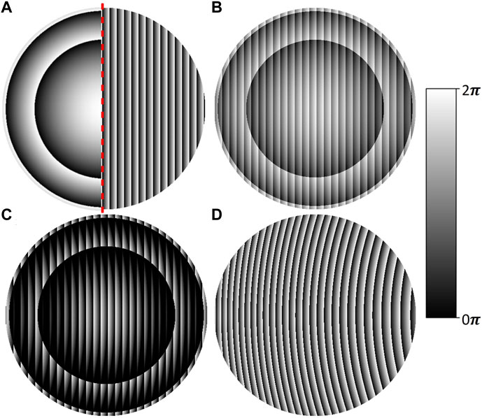
FIGURE 1. The phase distributions of single-input-multiple-output (SIMO) structures designed as the combination of two different types of diffractive optical elements (DOEs), phase diffractive lenses and phase blazed diffraction gratings, in various configurations, presented as gray-scale bitmaps; (A) SIMO1 structure—kinoform lens reversely merged by the substrate with the blazed diffraction grating; rotation indicated with a red dashed line; (B) SIMO2 structure—reduced matrices values of both DOEs phase distributions summed up to the 0-2π phase range; (C) SIMO3 structure—distribution obtained as lens’s phase distribution subtraction from the blazed diffraction gratings distribution with trimming negative values condition; (D) SIMO4 structure—lens’s phase distribution subtracted from the blazed diffraction grating phase distribution with 2π modulation.
The SIMO1 structure illustrated in Figure 1A was the first variant. SIMO1 was obtained as the combination of two separate phase distributions. The first component was a centrally symmetric kinoform lens with the phase distribution varying from 0 to 2π. The second component was blazed diffraction grating with the continuous phase changes from 0 to 2π. Both components were merged by their backsides. One of the components was rotated by 180° to the optical axis and in this way both components were connected by flat surfaces of their substrates. In Figure 1A, the rotation is marked with the red dashed line. Therefore, only half of each component is presented in the image. This design uses the functionalities of both components fully and consequently, unnecessary signal losses are minimalized.
The second structure, SIMO2, is shown in Figure 1B. In this method, the kinoform lens’s phase distribution was reduced to the range of 0-π, which corresponds to the gray-scale image pixel values in the range from 0 to 127. The same approach was used for the second component which was the blazed diffraction grating. In this way, both components of the structure had the same phase depth. In the next step, the pixel values of both components were summed up, creating a new DOE (SIMO2 structure) with the phase varying from 0 to 2π. The SIMO2 design method introduces a smaller radiation damping than the previously described SIMO1 structure. It is derived from the total thickness of the structure, which in the case of SIMO1 is locally even twice higher than SIMO2. Elements that are flat from one side are more prone to reduce the shadow effect (Suszek et al., 2013) which can reduce the efficiency of the diffractive element.
The SIMO3 structure is presented in Figure 1C. It was obtained by subtracting phase distributions of the kinoform lens and blazed diffraction grating which were two components of SIMO3. The phase distribution of each component varied in the range from 0 to 2π. Additionally, the condition trimming negative values to 0 was implemented during the design process. This design method resulted in the low pixel values of the great part of the SIMO3 phase distribution, which are dark areas in the gray-scale image presented in Figure 1C. These dark areas had a significant influence on the performance of the SIMO3 structure. The part of the incident radiation was not bent in the -1st diffraction order, but propagated to the 0th order of diffraction, which is described more precisely in the result section. However, lower radiation damping within the structure due to the lower thickness of the structure, smaller material compaction in the manufacturing process, and shorter manufacturing time are the advantages of such a solution.
The SIMO4 structure had the phase distribution generated with the last design method presented in this study and illustrated in Figure 1D. The SIMO4 structure phase distribution was the result of subtracting the kinoform lens and the blazed diffraction grating which were two components. The phase values of both components ranged from 0 to 2π. However, in this approach, 2π phase modulation was applied. This means that the SIMO4 structure can be described as an off-axis segment of a kinoform lens that focused incoming radiation in the off-axis focal spot. THz radiation diffracted on the structure by the deflection angle α. Therefore, the focal spot was located in the area of -1st diffraction order of the blazed diffraction grating used in the design process.
Additionally, the reference SIMO structure consisting of two DOEs was designed. The kinoform lens characterized by phase distribution varying from 0 to 2π was the first component. The binary diffraction grating represented by phase levels of 0 and π was the second component. The reference SIMO structure was obtained as a sum of both components’ phase distributions applying 2π phase modulation condition. Such a solution allows the SIMO reference structure to redirect incoming radiation into the 1st and -1st diffraction orders. The similar structures and their performance were more precisely described in our previous study (Komorowski et al., 2021a). The SIMO reference structure was used to compare the -1st diffraction order radiation redirection relative efficiency of SIMO 1-4 structures. The obtained phase distribution of SIMO reference DOE and the manufactured structure from COC material are presented in Figures 2A, B, respectively.
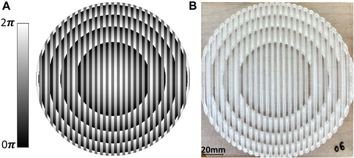
FIGURE 2. The reference single-input-multiple-output (SIMO) structure designed as a combination of different types of diffractive optical elements (DOEs), phase kinoform lenses and phase binary diffraction gratings; (A) phase distribution obtained as a sum of both components’ applying 2π phase modulation condition; (B) manufactured structure using fused deposition modeling (FDM) 3D printing technology from cyclic olefin copolymer (COC) material.
3 Manufacturing
Four generated SIMO diffractive structures coded as gray-scale bitmaps were extruded into 3D models. Each structure was characterized by a continuous phase change along its diameter with sharp phase drops from 2π to 0. Therefore, the pixels of the structures bitmap could be represented with the nodes extruded into levels according to pixel values corresponding to phase changes. Subsequently, nods were connected to the triangular mesh resulting in a 3D model creation. Such an approach can only be considered for structures with continuous phase changes and dense sampling used during the design. In such a case, the interpolation between nodes does not have a significant influence on the result. The considered levels depended on the material used in the manufacturing process and can be determined by the following formula (4):
where h is the height of the extrusion for a particular pixel, ϕ is the phase delay introduced by the pixel, x and y are the Cartesian coordinates, λ is the DWL of the structure and n is the refractive index of the material.
The FDM 3D printing method was chosen for the manufacturing of DOEs due to its wide range of possibilities, including fast and cheap prototyping, a broad range of available printing polymer and composite materials, and the high quality and precision of the manufacturing of THz passive optical elements considering wavelengths of sub-THz radiation. During the manufacturing process of DOEs, prevention from the deformation of the print is crucial as DOEs are highly sensitive to THz wave phase changes. Deformations might be caused, for instance, by warping the material during the printing process or bending the material during the cooling process. FDM technology minimizes deformations that are formed during the printing process. Furthermore, some polymer materials accessible for FDM technology are characterized by low shrinkage. Thus, there is the possibility of manufacturing broad and flat structures without huge deformations.
Various polymer materials used in FDM 3D printing were previously examined with the THz time-domain spectroscopy (TDS) method (Kaluza et al., 2022). In this way, the optical properties of the materials were determined. Figure 3 presents the comparison of the absorption coefficient α (solid lines) and the refractive index n (dashed lines) for several selected polymers in the frequency domain for the sub-THz and THz radiation range. The presented data concern cyclic olefin copolymer (COC), polyamide 12 (PA12), polycarbonate (PC), polyethylene terephthalate glycol (PETG), polylactic acid (PLA), polypropylene (PP), polyvinyl alcohol (PVA).
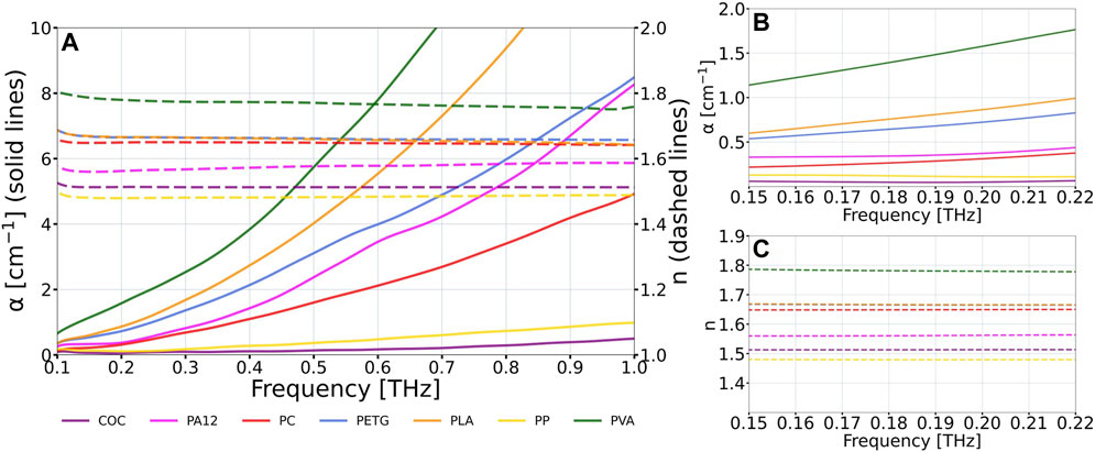
FIGURE 3. The absorption coefficient α (solid lines) and the refractive index n (dashed lines) of the selected polymers used for the FDM 3D printing obtained from THz time-domain spectroscopy (THz TDS). The study was carried out on cyclic olefin copolymer (COC), polyamide 12 (PA12), polycarbonate (PC), polyethylene terephthalate glycol (PETG), polylactic acid (PLA), polypropylene (PP), polyvinyl alcohol (PVA). (A) the optical properties of the materials in the frequency domain within the range of 100 GHz to 1 THz; (B) the absorption coefficient and (C) the refractive index of the materials for the experimental evaluation frequency region of 150 GHz–220 GHz.
The data reveals the significant differences in the absorption coefficient of polymer materials in the THz radiation range. COC has the lowest absorption coefficient and therefore it introduces minimal dumping during propagation of THz waves within the structure, making it an appropriate material for manufacturing phase DOEs. The refractive index of COC for the DWL corresponding to the frequency of 160 GHz is approximately equal to 1.513. Thus, COC material was chosen for the manufacturing of THz SIMO lenses.
The THz SIMO structures were manufactured with the nozzle diameter of 400 μm, which determined the line width on the print of 450 μm corresponding to the horizontal resolution of the print. The height of the layer of the print was equal to 100 μm, defining the vertical resolution of the print. The manufactured THz SIMO lenses are presented in Figure 4.
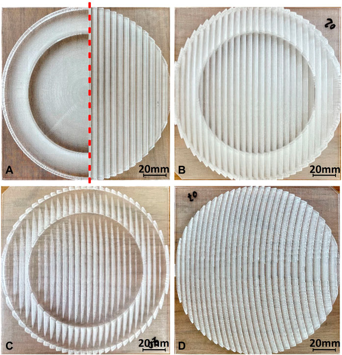
FIGURE 4. Images of 3D printed single-input-multiple-output (SIMO) structures using fused deposition modeling (FDM) technology from cyclic olefin copolymer (COC) material. Structures were designed as a combination of two different types of diffractive optical elements (DOEs), phase diffractive lenses and phase blazed diffractive gratings, in various configurations; (A) SIMO1 structure—kinoform lens reversely merged by substrate with blazed diffraction grating; rotation denoted with a red dashed line; (B) SIMO2 structure—reduced matrices values of both DOEs phase distributions summed up to the 2π range phase distribution; (C) SIMO3 structure—distribution obtained as lens’s phase distribution subtraction from blazed diffraction gratings distribution with trimming negative values condition; (D) SIMO4 structure—lens’s phase distribution subtracted from blazed diffraction grating phase distribution with 2π modulation.
4 The results
The performance of all four designed SIMO structures was verified both in numerical simulations and in an experimental evaluation. The results of this analysis are presented below.
4.1 The numerical simulations
The proper functioning of the designed THz SIMO structures presented in Figure 1 was simulated numerically using a modified convolution method (Sypek, 1995). The previously determined Gaussian beam distribution of the radiation source was used to illuminate objects located perpendicularly to the optical axis. Thus, the obtained simulation results corresponded more accurately to the actual performance of the SIMO lenses in the experimental setup. In the plane corresponding to the focal length f of 700 mm behind each structure, the intensity distribution was analyzed for various frequencies in the range from 150 GHz to 220 GHz every 10 GHz.
The results obtained for every SIMO structure and reference structure for different frequencies were combined into single graphs and presented in Figure 5. The presented data concerns the area of the −1st diffraction order. Different colors in Figure 5 correspond to different frequencies.
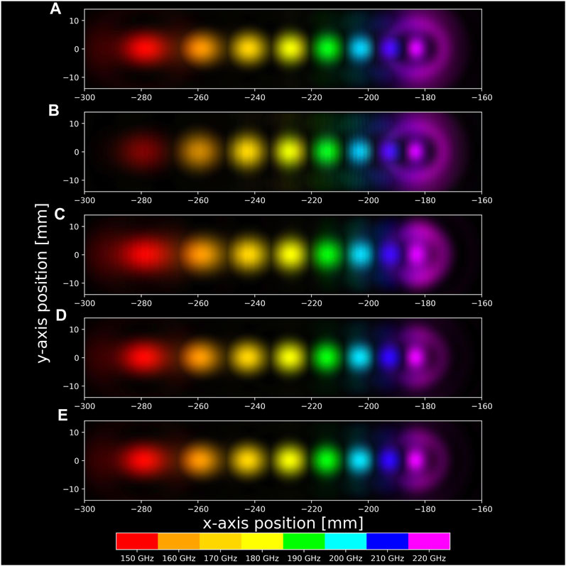
FIGURE 5. Numerical simulation results of four different single-input-multiple-output (SIMO) structures and SIMO reference structure showing the intensity distribution of −1st diffraction order for different THz frequencies represented with various colors. The graphs relate to (A) SIMO1 structure—kinoform lens reversely merged by the substrate with the blazed diffraction grating; rotation is indicated with a red dashed line; (B) SIMO2 structure—reduced matrix values of both DOEs phase distributions summed up to the 2π range phase distribution; (C) SIMO3 structure—distribution obtained as lens’s phase distribution subtraction from the blazed diffraction grating distribution with trim negative values condition; (D) SIMO4 structure—lens’s phase distribution subtracted from the blazed diffraction grating phase distribution with 2π modulation; (E) SIMO reference structure obtained as a sum of binary grating phase distribution and kinoform lens phase distribution applying 2π phase modulation condition.
Each simulation result clearly indicates the spatial separation of the signals according to the illuminated frequency of the THz wave. Thus, as expected, each of the four SIMO structures performs as a spatial frequency demultiplexer at the numerical simulation stage. Similarly, for the reference SIMO structure, the correct performance of the structure was found.
4.2 The optical setup
The optical setup used in the experiment contained: the source of THz radiation, a parabolic mirror, the measured structure, and THz detector. Its scheme is presented in Figure 6. The divergent spherical tunable monochromatic radiation was emitted from the VDI Schottky diode-based frequency multiplier. Then, generated THz beam illuminated the parabolic mirror located at a distance of about 620 mm from the radiation source corresponding to its focal length. Thus, the Gaussian beam distribution propagated in the form of a quasi-plane monochromatic wave in a free space.
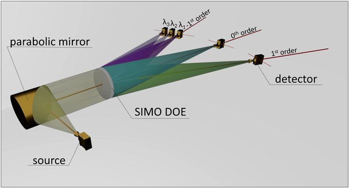
FIGURE 6. The optical setup used for evaluation of THz single-input-multiple-output (SIMO) diffractive optical elements (DOEs). The system allowed for gathering of experimental data for the −1st, 0th, and 1st diffraction orders.
Collimated radiation illuminated the evaluated SIMO structure. The DOE bent the incident radiation according to the frequency in the -1st order of diffraction and focused it into the focal spot in a finite distance that corresponds to the parameters used in the design stage. During experimental measurements the detector (Schottky diode placed in a waveguide with a conical horn antenna attached) with the acceptance angle of 13° corresponding to full 3 dB beamwidth was used as a detector. Figure 6 presents the beam trajectory, including minor 0th and 1st diffraction orders.
4.3 The experimental evaluation
All four manufactured SIMO structures presented in Figure 4 and reference SIMO structure shown in Figure 2B were experimentally evaluated in the THz optical setup. The setup scheme is shown in Figure 6. Three areas corresponding to the −1st, 0th, and 1st diffraction orders were examined.
In accordance with the assumptions and numerical simulation results, most intensity is supposed to be redirected and focused into the −1st diffraction order. However, some part of the radiation power (increasing with the frequency shift from the DWL) also propagates to the 0th diffraction order. Another crucial area for the examination is where the 1st diffraction order occurs. The measurements of 0th and 1st diffraction orders make it possible to determine the relative efficiencies of the developed structures. Furthermore, the measurements of the 1st diffraction order provided the information about the degree of redirection asymmetry introduced by the SIMO structures, demonstrating whether the structures function correctly. For the 0th order of diffraction, the scan was performed perpendicularly to the optical axis. However, for the −1st and 1st diffraction orders, the scanned area was rotated in a way that the incident radiation was orthogonally to the studied area (as shown in Figure 6). Therefore, the incident radiation was correctly collected within the acceptance angle of the detector (Komorowski et al., 2022). Such a procedure is necessary considering the off-axis measurements.
The scans were performed horizontally through the focal spots for every diffraction order under consideration. The intensity distribution cross-sections for different frequencies are presented in Figure 7. The data presented in Figures 7A–D corresponds to the measurements of the SIMO1-4 structures, respectively. The shown data distributions are normalized because of the non-flat spectral source characteristics.
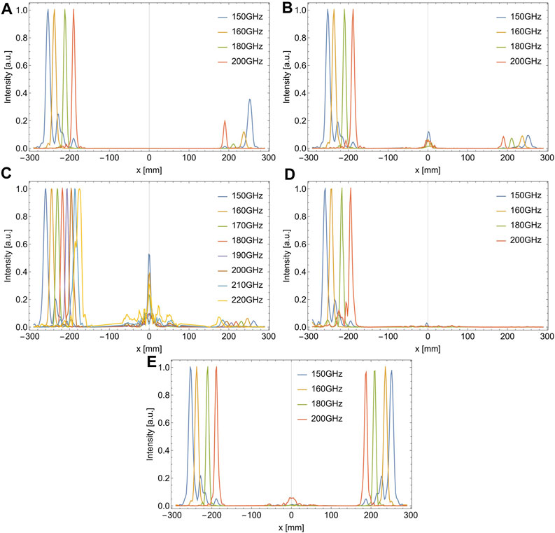
FIGURE 7. Experimental results for four different single-input-multiple-output (SIMO) structures and reference SIMO structure demonstrating horizontal cross-section of intensity distribution along −1st, 0th, and 1st diffraction orders for different THz frequencies. The presented data concerns: (A) SIMO1 structure—kinoform lens reversely merged by substrate with blazed diffraction grating; rotation denoted with a red dashed line; (B) SIMO2 structure—reduced matrices values of both DOEs phase distributions summed up to the 2π range phase distribution; (C) SIMO3 structure—distribution obtained as lens’s phase distribution subtraction from blazed diffraction gratings distribution with trimming negative values condition; (D) SIMO4 structure—lens’s phase distribution subtracted from blazed diffraction grating phase distribution with 2π modulation; (E) SIMO reference structure—designed as a combination of phase kinoform lenses and phase binary diffraction gratings.
For SIMO3 detailed measurements were performed. The data for SIMO3 was gathered for eight frequencies ranging from 150 GHz to 220 GHz every 10 GHz. The spatial separation of frequencies was observed. Subsequently, other structures were examined with four frequencies of 150 GHz, 160 GHz, 180 GHz, and 200 GHz. The analysis of these four frequencies allows to verify the spectral resolution (separation of 150 GHz and 160 GHz is shown for each structure) and performance in the range from 150 GHz to 200 GHz.
It needs to be highlighted that the frequency of 150 GHz is below the DWL frequency. However, gathering and presenting data for the frequency deviating from the intended functionality is the additional achievement and an interesting topic for discussion. Nevertheless, it should be emphasized that the focal spot for 150 GHz frequency is widely shifted from the optical axis and thus, dilating of the focal spot occurs. Moreover, the detector’s position was set favoring a smaller deflection angle. Consequently, some deformations of the signal occurred and they can be seen as artifacts on the right side of 150 GHz intensity peak on each of Figure 4 characteristics. These deformations are probably the results of internal reflections in horn shape antenna which is the detector’s outer component.
The performance of SIMO1-4 structures compared with the reference SIMO structure is presented in Table 1 and Table 2. The data concerns the maximum measured voltage values in the areas of the −1st and 0th and 1st diffraction orders. Table 1 analyzes 150 GHz and 160 GHz frequencies, while Table 2 refers to 180 GHz and 200 GHz frequencies. The measured voltage is directly proportional to the THz intensity gathered by the detector. The 1st diffraction order of the reference SIMO structure is not further discussed since it is not the area of interest of this study. However, DOE containing a binary grating component redirects radiation symmetrically into the −1st and 1st diffraction orders, which is more precisely described in our previous work (Komorowski et al., 2021a). Additionally, in Table 3 the relative efficiency of SIMO1-4 structures is shown. The presented data describes the ratio of the maximum intensity redirected by SIMO1-4 structures compared with SIMO reference structure in the −1st diffraction order. While analyzing the data, it can be concluded that performance of SIMO1, SIMO2, and SIMO4 structures is significantly better than the SIMO reference structure.
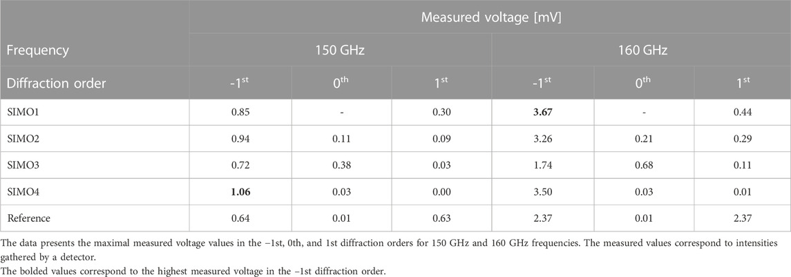
TABLE 1. The comparison of the experimental results performed for four different single-input-multiple-output (SIMO) structures.
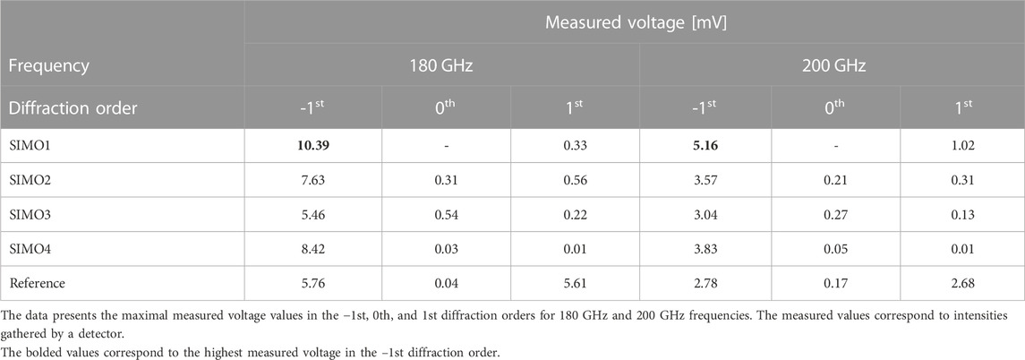
TABLE 2. The comparison of the experimental results performed for four different single-input-multiple-output (SIMO) structures.
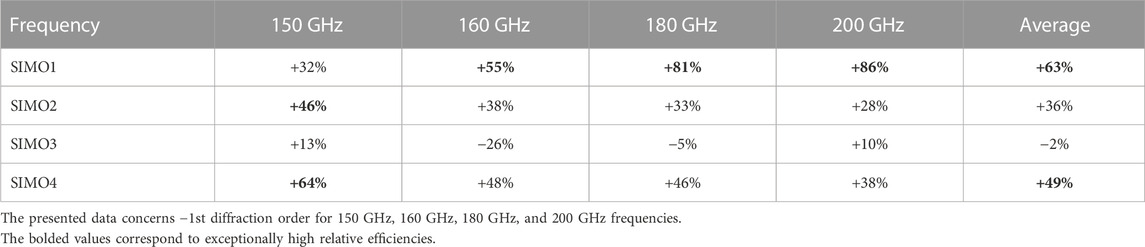
TABLE 3. The relative efficiency of Single-input-multiple-output (SIMO) structures compared to SIMO reference structure.
The experimental results of the SIMO1 structure are presented in Figure 7A. The structure obtained by merging the phase kinoform lens and the phase blazed diffraction grating and connected by their substrates redirected most of the incident radiation in the −1st diffraction order. The radiation was properly bent for various THz frequencies that differ from each other by 10 GHz and then by 20 GHz. Furthermore, all examined frequencies were spatially separated in the −1st diffraction order, which can be observed as separated intensity peaks in the left part of Figure 7A. When frequencies deviate from the DWL, artifacts in other orders of diffraction can be observed, especially for 150 GHz frequency. Less impact was observed for the frequencies higher than the DWL. It can be seen that the undesired radiation intensity increased in the 1st diffraction order for the frequencies of 150 GHz and 200 GHz. For the frequencies closer to the DWL, this effect is insignificant. The 0th diffraction order was not appropriately measured, and data were not included in the analysis. However, the signal beyond the spectral noise was not observed during the measurements. According to the data presented in Table 1 and Table 2, out of the structures under evaluation, SIMO1 structure redirected the highest intensity into the −1st diffraction order for 160 GHz, 180 GHz, and 200 GHz frequencies. Moreover, as seen in Table 3, SIMO1 structure relative efficiency is even 86% higher for 200 GHz frequency than SIMO reference structure. Furthermore, for SIMO1 structure, average THz radiation (concerning 150 GHz–200 GHz radiation range) bent into the −1st diffraction order is 63% higher than the reference SIMO structure.
Figure 7B shows the cross-section intensity distribution through the diffraction orders of SIMO2 structure, designed as the sum of reduced phase distributions of both DOE components. All four examined frequencies of 150 GHz, 160 GHz, 180 GHz, and 200 GHz were spatially separated in the −1st diffraction order. For the SIMO2 structure, unwanted artifacts in the −1st diffraction order were less significant than for the SIMO1 structure. At the same time, less part of the radiation was redirected into the 1st diffraction order, where similar normalized intensities for all four frequencies under the measurement occurred. The insignificant part of the radiation was redirected into the 0th diffraction order, especially for 150 GHz frequency which had the strongest influence of the artifacts in the −1st order of diffraction in the case of SIMO1 structure. Nevertheless, according to the data in Table 1, Table 2, and Table 3, SIMO2 structure redirected less intensity into the −1st diffraction order than the SIMO1 and the SIMO4 structures. It happened except 150 GHz frequency where SIMO2 performed better than the SIMO1 and the SIMO3 structures and bent 46% higher intensity than the SIMO reference structure. Considering all four frequencies, the relative efficiency of the SIMO2 structure was 36% higher than the SIMO reference structure.
The experimental results for the SIMO3 structure are presented in Figure 7C. The SIMO3 structure was examined with eight frequencies in the range from 150 GHz to 220 GHz every 10 GHz. All eight frequencies were bent and focused in the −1st diffraction order. They were separated spatially, which is illustrated in the left part of Figure 7C as shifted peaks along the x-axis, where different colors represent different frequencies. Deviating from the DWL, the peaks start to overlap each other, which can be noticed for the higher frequencies of 200 GHz, 210 GHz, and 220 GHz. This phenomenon does not occur above 70% of peak heights. Thus, all eight different frequencies were clearly separated, and the spatial frequency-division demultiplexing occurred. However, for the applied design parameters, proper peaks separation occurred for the frequencies in the range from 150 GHz to 210 GHz.
Analyzing data shown in Table 1, Table 2 and Figure 7C, it can be stated that the insignificant part of the radiation was bent into the 1st diffraction order. It can be observed that the significant part of the radiation propagated in the 0th diffraction order. It is the result of the design method. Due to the negative values trimming condition in the design stage, the manufactured SIMO3 structure contains flat areas where incident radiation was not bent correctly in the −1st diffraction order. However, the intensity in 0th diffraction order still does not exceed 53% of the corresponding height of the intensity peaks in the −1st diffraction order for any of the frequencies examined. It should be mentioned that the highest 0th influence occurs for the frequencies of 150 GHz and highly deviated from the DWL - 220 GHz. Considering the data presented in Table 3, the performance of the SIMO3 structure is the worst of the evaluated SIMO1-4 structures but still similar to the SIMO reference structure. It is the real achievement to spatially separate eight different frequencies in the range from 150 GHz to 220 GHz every 10 GHz with a single DOE. It is essential to emphasize that the SIMO3 structure was capable of meeting the demands of the object of this study. Furthermore, it is noteworthy that the remaining structures perform better. Another important aspect is that this approach highlights a structure that requires significantly less material input in the production process (which can be advantageous in certain cases).
The experimental results of the SIMO4 structure are shown in Figure 7D, and the maximal gathered signals in Table 1 and Table 2. All four examined frequencies were spatially separated in the −1st diffraction order presented in the left part of Figure 7D. Almost no radiation was diffracted into the 0th and 1st diffraction order. However, unexpectedly for two frequencies (150 GHz and 200 GHz), unwanted artifacts in the detected signal occurred that were not observed for 200 GHz for other examined structures. Analyzing Table 3, it can be observed that despite artifacts, the SIMO4 structure redirected the highest intensity into the −1st diffraction order for 150 GHz, which is 64% higher than for the reference SIMO structure. Considering all four examined frequencies in the −1st diffraction order, the average performance of the SIMO4 structure is 49% higher than performance of the reference SIMO structure.
5 Conclusion
In this paper, four different structures realizing spatial frequency division demultiplexing of THz radiation are presented. The authors’ previous studies in this area focused on multi-focal spot beam demultiplexing (Komorowski et al., 2021b) and DOEs for spatial demultiplexing with the redundancy application (Komorowski et al., 2021a). This time, four structures were presented for spatial demultiplexing of THz radiation concerning one area of single diffraction order. This presented solution guaranteed the minimization of signal losses. The novel design method made it possible to achieve an average relative efficiency 63% higher for the SIMO1 structure and 49% higher for the SIMO4 structure than previously reported DOEs based on the binary gratings. Considering the individual frequencies of 180 GHz and 200 GHz, the SIMO1 structure produced 81% and 86% better results than the previously reported reference SIMO structure. Therefore, the authors recommend SIMO1 and SIMO4 structures for further research and potential applications in future 6G telecommunication technology. However, it needs to be highlighted that SIMO4 was manufactured as a single component. In contrast, the SIMO1 structure was manufactured in two separate parts that are further connected. Thus, Fresnel reflections may occur at the connection interface, which should be compensated by the application of a binding agent, such as wax or transparent immersion oils suitable for the THz range. Additionally, unwanted misalignment between both components can occur. This is why the SIMO1 structure is more challenging in terms of proper production. However, considering production methods that allow for the fabrication of the SIMO1 structure as a single element, the authors lean toward recommending the SIMO1 structure for future telecommunication applications.
All four presented SIMO structures were differently designed as the combinations of two DOEs which were the phase kinoform lens and the blazed diffraction grating. As a result it created new types of DOEs. The blazed kinoform grating component redirected and spatially separated incident THz radiation in a single diffraction order according to the applied frequency. The kinoform lens component was responsible for focusing spatially separated radiation creating focal spots in the finite designed distance. The SIMO structures were examined in numerical simulation and these showed the promising results where eight frequencies in the range of 150 GHz–220 GHz every 10 GHz were spatially separated. Subsequently, the SIMO structures were manufactured using 3D printing FDM technology from COC material, which THz optical properties are the best for manufacturing phase DOEs. The method proposed in this study allows for the design of SIMO structures at any desired frequency within the THz radiation range, and manipulation of the design parameters to achieve greater spatial separation of signals. It is also worth emphasizing that in this case, the 3D printing method used can be replaced by any production method, provided that the structures are fabricated from a transparent material suitable for the given radiation range.
The SIMO structures were experimentally evaluated. One structure (SIMO3) was verified for eight different frequencies in the range from 150 GHz to 220 GHz every 10 GHz. All eight frequencies were successfully spatially separated in the evaluating optical setup. However, for six frequencies in the 160 GHz–210 GHz range a proper separation was observed, where unwanted artifacts and excessive signals overlapping did not occur. Other SIMO structures were examined for four frequencies of 150 GHz, 160 GHz, 180 GHz, and 200 GHz. All four verified structures separated THz frequencies correctly. However, the SIMO1 structure showed the highest relative efficiency considering the −1st diffraction order, and the SIMO4 structure provided the lowest losses in the 0th and 1st diffraction orders. Thus, the SIMO1 and SIMO4 structures can be chosen for further research in this area.
The presented study fits applications for 6G technology telecommunication systems as spatial frequency division demultiplexing components for the THz radiation band. The application of DOEs manufactured from the highly transparent material like COC can be used in various THz systems where free space propagation is the crucial factor.
Data availability statement
The raw data supporting the conclusion of this article will be made available by the authors, without undue reservation.
Author contributions
MK: Data curation, Formal Analysis, Investigation, Methodology, Software, Visualization, Writing–original draft. PK: Conceptualization, Methodology, Visualization, Writing–review and editing. PZ: Methodology, Visualization, Writing–review and editing. AS: Conceptualization, Funding acquisition, Project administration, Supervision, Writing–review and editing.
Funding
The author(s) declare financial support was received for the research, authorship, and/or publication of this article. The research was funded by the National Science Centre, Poland under the OPUS-18 program (2019/35/B/ST7/03909).
Acknowledgments
The authors would like to thank Marcin Przerwa who helped in performing simulations and experimental measurements as a part of his MSc. Thesis under the supervision of AS and PZ.
Conflict of interest
The authors declare that the research was conducted in the absence of any commercial or financial relationships that could be construed as a potential conflict of interest.
Publisher’s note
All claims expressed in this article are solely those of the authors and do not necessarily represent those of their affiliated organizations, or those of the publisher, the editors and the reviewers. Any product that may be evaluated in this article, or claim that may be made by its manufacturer, is not guaranteed or endorsed by the publisher.
References
Akyildiz, I. F., Jornet, J. M., and Han, C. (2014). Terahertz band: next frontier for wireless communications. Phys. Commun. 12, 16–32. doi:10.1016/j.phycom.2014.01.006
Buralli, D. A., Morris, G. M., and Rogers, J. R. (1989). Optical performance of holographic kinoforms. Appl. Opt. 28, 976. doi:10.1364/ao.28.000976
Chaccour, C., Soorki, M. N., Saad, W., Bennis, M., Popovski, P., and Debbah, M. (2022). Seven defining features of terahertz (THz) wireless systems: a fellowship of communication and sensing. IEEE Commun. Surv. Tutorials 24, 967–993. doi:10.1109/comst.2022.3143454
Chen, H., Sarieddeen, H., Ballal, T., Wymeersch, H., Alouini, M.-S., and Al-Naffouri, T. Y. (2022). A tutorial on terahertz-band localization for 6g communication systems. IEEE Commun. Surv. Tutorials 24, 1780–1815. doi:10.1109/comst.2022.3178209
Chen, Z., Ma, X., Zhang, B., Zhang, Y., Niu, Z., Kuang, N., et al. (2019). A survey on terahertz communications. China Commun. 16, 1–35. doi:10.12676/j.cc.2019.02.001
Cunningham, P. D., Valdes, N. N., Vallejo, F. A., Hayden, L. M., Polishak, B., Zhou, X.-H., et al. (2011). Broadband terahertz characterization of the refractive index and absorption of some important polymeric and organic electro-optic materials. J. Appl. Phys. 109, 043505. doi:10.1063/1.3549120
Ducournau, G., Szriftgiser, P., Pavanello, F., Peytavit, E., Zaknoune, M., Bacquet, D., et al. (2014). THz communications using photonics and electronic devices: the race to data-rate. J. Infrared, Millim. Terahertz Waves 36, 198–220. doi:10.1007/s10762-014-0112-x
Faisal, A., Sarieddeen, H., Dahrouj, H., Al-Naffouri, T. Y., and Alouini, M.-S. (2020). Ultramassive MIMO systems at terahertz bands: prospects and challenges. IEEE Veh. Technol. Mag. 15, 33–42. doi:10.1109/mvt.2020.3022998
Fan, S., Li, T., Zhou, J., Liu, X., Liu, X., Qi, H., et al. (2017). Terahertz non-destructive imaging of cracks and cracking in structures of cement-based materials. AIP Adv. 7, 115202. doi:10.1063/1.4996053
Federici, J. F., Schulkin, B., Huang, F., Gary, D., Barat, R., Oliveira, F., et al. (2005). THz imaging and sensing for security applications—explosives, weapons and drugs. Semicond. Sci. Technol. 20, S266–S280. doi:10.1088/0268-1242/20/7/018
Fedulova, E. V., Nazarov, M. M., Angeluts, A. A., Kitai, M. S., Sokolov, V. I., and Shkurinov, A. P. (2012). “Studying of dielectric properties of polymers in the terahertz frequency range,” in SPIE proceedings. Editors V. V. Tuchin, E. A. Genina, and I. V Meglinski. (SPIE). doi:10.1117/12.923855
Han, C., Wu, Y., Chen, Z., and Wang, X. (2019). Terahertz communications (teracom): challenges and impact on 6g wireless systems. arXiv preprint arXiv:1912.06040.
Han, D., Lee, K., Lim, J., Hong, S. S., Kim, Y. K., and Ahn, J. (2013). Terahertz lens made out of natural stone. Appl. Opt. 52, 8670. doi:10.1364/ao.52.008670
He, J., Dong, T., Chi, B., and Zhang, Y. (2020). Metasurfaces for terahertz wavefront modulation: a review. J. Infrared, Millim. Terahertz Waves 41, 607–631. doi:10.1007/s10762-020-00677-3
IEEE (2017). IEEE standard for high data rate wireless multi-media networks–amendment 2: 100 gb/s wireless switched point-to-point physical layer. doi:10.1109/ieeestd.2017.8066476
Jiang, W., Han, B., Habibi, M. A., and Schotten, H. D. (2021). The road towards 6g: a comprehensive survey. IEEE Open J. Commun. Soc. 2, 334–366. doi:10.1109/ojcoms.2021.3057679
Kaluza, M., Surma, M., Komorowski, P., Walczakowski, M., and Siemion, A. (2022). “THz optical properties of different 3d printing polymer materials in relation to FTIR, Raman, and XPS evaluation techniques,” in 2022 47th International Conference on Infrared, Millimeter and Terahertz Waves (IRMMW-THz) (IEEE). doi:10.1109/irmmw-thz50927.2022.9895845
Kleine-Ostmann, T., and Nagatsuma, T. (2011). A review on terahertz communications research. J. Infrared, Millim. Terahertz Waves 32, 143–171. doi:10.1007/s10762-010-9758-1
Knipper, R., Brahm, A., Heinz, E., May, T., Notni, G., Meyer, H.-G., et al. (2015). THz absorption in fabric and its impact on body scanning for security application. IEEE Trans. Terahertz Sci. Technol. 5, 999–1004. doi:10.1109/tthz.2015.2474115
Komorowski, P., Czerwińska, P., Kaluza, M., Surma, M., Zagrajek, P., Sobczyk, A., et al. (2021a). Frequency division multiplexing of terahertz waves realized by diffractive optical elements. Appl. Sci. 11, 6246. doi:10.3390/app11146246
Komorowski, P., Czerwińska, P., Surma, M., Zagrajek, P., Piramidowicz, R., and Siemion, A. (2021b). Three-focal-spot terahertz diffractive optical element-iterative design and neural network approach. Opt. Express 29, 11243. doi:10.1364/oe.418059
Komorowski, P., and Siemion, A. (2022). “THz diffractive optics designed with neural networks,” in 2022 47th International Conference on Infrared, Millimeter and Terahertz Waves (IRMMW-THz) (IEEE). doi:10.1109/irmmw-thz50927.2022.9895944
Komorowski, P., Siemion, A., Walczakowski, M., and Zagrajek, P. (2022). The role of the directivity of various THz detectors in multiplexing systems. Appl. Sci. 12, 3545. doi:10.3390/app12073545
Kress, B. C., and Meyrueis, P. (2000). Digital diffractive optics. Chichester, England: John Wiley and Sons.
Liu, C., Niu, L., Wang, K., and Liu, J. (2016). 3d-printed diffractive elements induced accelerating terahertz airy beam. Opt. Express 24, 29342. doi:10.1364/oe.24.029342
Liu, Z., Liu, J., Zeng, Y., and Ma, J. (2020). Covert wireless communication in IoT network: from AWGN channel to THz band. IEEE Internet Things J. 7, 3378–3388. doi:10.1109/jiot.2020.2968153
Luo, Y., Mengu, D., Yardimci, N. T., Rivenson, Y., Veli, M., Jarrahi, M., et al. (2019). Design of task-specific optical systems using broadband diffractive neural networks. Light Sci. Appl. 8, 112. doi:10.1038/s41377-019-0223-1
Machado, F., Zagrajek, P., Ferrando, V., Monsoriu, J. A., and Furlan, W. D. (2019). Multiplexing THz vortex beams with a single diffractive 3-d printed lens. IEEE Trans. Terahertz Sci. Technol. 9, 63–66. doi:10.1109/tthz.2018.2883831
Massaouti, M., Daskalaki, C., Gorodetsky, A., Koulouklidis, A. D., and Tzortzakis, S. (2013). Detection of harmful residues in honey using terahertz time-domain spectroscopy. Appl. Spectrosc. 67, 1264–1269. doi:10.1366/13-07111
Mehdi, I., Siles, J., Chen, C. P., and Jornet, J. M. (2018). “THz technology for space communications,” in 2018 Asia-Pacific Microwave Conference (APMC) (IEEE). doi:10.23919/apmc.2018.8617235
Mínguez-Vega, G., Mendoza-Yero, O., Lancis, J., Gisbert, R., and Andrés, P. (2008). Diffractive optics for quasi-direct space-to-time pulse shaping. Opt. Express 16, 16993. doi:10.1364/oe.16.016993
Monnai, Y., Altmann, K., Jansen, C., Hillmer, H., Koch, M., and Shinoda, H. (2013). Terahertz beam steering and variable focusing using programmable diffraction gratings. Opt. Express 21, 2347. doi:10.1364/oe.21.002347
Nagatsuma, T., Horiguchi, S., Minamikata, Y., Yoshimizu, Y., Hisatake, S., Kuwano, S., et al. (2013). Terahertz wireless communications based on photonics technologies. Opt. Express 21, 23736. doi:10.1364/oe.21.023736
Ngo, T. D., Kashani, A., Imbalzano, G., Nguyen, K. T., and Hui, D. (2018). Additive manufacturing (3d printing): a review of materials, methods, applications and challenges. Compos. Part B Eng. 143, 172–196. doi:10.1016/j.compositesb.2018.02.012
O’Hara, J. F., Ekin, S., Choi, W., and Song, I. (2019). A perspective on terahertz next-generation wireless communications. Technologies 7, 43. doi:10.3390/technologies7020043
Palka, N., Szustakowski, M., Kowalski, M., Trzcinski, T., Ryniec, R., Piszczek, M., et al. (2012). “THz spectroscopy and imaging in security applications,” in 2012 19th International Conference on Microwaves, Radar and Wireless Communications (IEEE). doi:10.1109/mikon.2012.6233513
Petrov, V., Kokkoniemi, J., Moltchanov, D., Lehtomaki, J., Koucheryavy, Y., and Juntti, M. (2018). Last meter indoor terahertz wireless access: performance insights and implementation roadmap. IEEE Commun. Mag. 56, 158–165. doi:10.1109/mcom.2018.1600300
Piesiewicz, R., Jacob, M., Koch, M., Schoebel, J., and Kurner, T. (2008). Performance analysis of future multigigabit wireless communication systems at THz frequencies with highly directive antennas in realistic indoor environments. IEEE J. Sel. Top. Quantum Electron. 14, 421–430. doi:10.1109/jstqe.2007.910984
Sahin, S., Nahar, N. K., and Sertel, K. (2019). Dielectric properties of low-loss polymers for mmW and THz applications. J. Infrared, Millim. Terahertz Waves 40, 557–573. doi:10.1007/s10762-019-00584-2
Shahrubudin, N., Lee, T., and Ramlan, R. (2019). An overview on 3d printing technology: technological, materials, and applications. Procedia Manuf. 35, 1286–1296. doi:10.1016/j.promfg.2019.06.089
Siemion, A. (2019). Terahertz diffractive optics—smart control over radiation. J. Infrared, Millim. Terahertz Waves 40, 477–499. doi:10.1007/s10762-019-00581-5
Siemion, A. (2020). The magic of optics—an overview of recent advanced terahertz diffractive optical elements. Sensors 21, 100. doi:10.3390/s21010100
Siemion, A., Komorowski, P., Surma, M., Ducin, I., Sobotka, P., Walczakowski, M., et al. (2020). Terahertz diffractive structures for compact in-reflection inspection setup. Opt. Express 28, 715. doi:10.1364/oe.382272
Siemion, A., Siemion, A., Makowski, M., Suszek, J., Bomba, J., Czerwiński, A., et al. (2012). Diffractive paper lens for terahertz optics. Opt. Lett. 37, 4320. doi:10.1364/ol.37.004320
Sun, J., and Hu, F. (2019). Three-dimensional printing technologies for terahertz applications: a review. Int. J. RF Microw. Computer-Aided Eng. 30. doi:10.1002/mmce.21983
Surma, M., Ducin, I., Sypek, M., Zagrajek, P., and Siemion, A. (2018). Optimization of THz diffractive optical elements thickness. Photonics Lett. Pol. 10, 115. doi:10.4302/plp.v10i4.873
Surma, M., Kaluza, M., Komorowski, P., and Siemion, A. (2022). “Terahertz hologram for homogenous illumination,” in 2022 47th International Conference on Infrared, Millimeter and Terahertz Waves (IRMMW-THz) (IEEE). doi:10.1109/irmmw-thz50927.2022.9895983
Suszek, J., Sypek, M., Makowski, M., Garet, F., Ducin, I., Kakarenko, K., et al. (2013). Evaluation of the shadow effect in terahertz kinoform gratings. Opt. Lett. 38, 1464–1466. doi:10.1364/ol.38.001464
Sypek, M. (1995). Light propagation in the fresnel region. new numerical approach. Opt. Commun. 116, 43–48. doi:10.1016/0030-4018(95)00027-6
Tao, Y. H., Fitzgerald, A. J., and Wallace, V. P. (2020). Non-contact, non-destructive testing in various industrial sectors with terahertz technology. Sensors 20, 712. doi:10.3390/s20030712
Tribe, W. R., Newnham, D. A., Taday, P. F., and Kemp, M. C. (2004). “Hidden object detection: security applications of terahertz technology,” in SPIE proceedings. Editor R. J Hwu. (SPIE). doi:10.1117/12.543049
Trofimov, V., and Varentsova, S. (2016). Essential limitations of the standard THz TDS method for substance detection and identification and a way of overcoming them. Sensors 16, 502. doi:10.3390/s16040502
Tzydynzhapov, G., Gusikhin, P., Muravev, V., Dremin, A., Nefyodov, Y., and Kukushkin, I. (2020). New real-time sub-terahertz security body scanner. J. Infrared, Millim. Terahertz Waves 41, 632–641. doi:10.1007/s10762-020-00683-5
Veli, M., Mengu, D., Yardimci, N. T., Luo, Y., Li, J., Rivenson, Y., et al. (2021). Terahertz pulse shaping using diffractive surfaces. Nat. Commun. 12, 37. doi:10.1038/s41467-020-20268-z
Wietzke, S., Jansen, C., Reuter, M., Jung, T., Kraft, D., Chatterjee, S., et al. (2011). Terahertz spectroscopy on polymers: a review of morphological studies. J. Mol. Struct. 1006, 41–51. doi:10.1016/j.molstruc.2011.07.036
Yang, L., Guo, T., Zhang, X., Cao, S., and Ding, X. (2018). Toxic chemical compound detection by terahertz spectroscopy: a review. Rev. Anal. Chem. 37. doi:10.1515/revac-2017-0021
Keywords: THz radiation, THz optics, MIMO systems, passive diffractive optical elements, additive manufacturing, multiplexing, diffraction grating
Citation: Kaluza M, Komorowski P, Zagrajek P and Siemion A (2023) Terahertz focusing blazed diffractive optical elements for frequency demultiplexing. Adv. Opt. Technol. 12:1310578. doi: 10.3389/aot.2023.1310578
Received: 09 October 2023; Accepted: 20 November 2023;
Published: 01 December 2023.
Edited by:
Allen Yi, The Ohio State University, United StatesReviewed by:
Georgios Ctistis, Institute for Nanophotonics e.V., GermanyPaulo Lourenço, Lisbon Higher Institute of Engineering (ISEL), Portugal
Copyright © 2023 Kaluza, Komorowski, Zagrajek and Siemion. This is an open-access article distributed under the terms of the Creative Commons Attribution License (CC BY). The use, distribution or reproduction in other forums is permitted, provided the original author(s) and the copyright owner(s) are credited and that the original publication in this journal is cited, in accordance with accepted academic practice. No use, distribution or reproduction is permitted which does not comply with these terms.
*Correspondence: Mateusz Kaluza, bWF0ZXVzei5rYWx1emEuZG9rdEBwdy5lZHUucGw=