 Tomaso Trombetti
 Michele Palermo
 Antoine Dib
 Stefano Silvestri
- Department of Civil, Chemical, Environmental, and Materials Engineering, University of Bologna, Bologna, Italy
Several design methods aimed at sizing the viscous dampers to be inserted in building structures have been proposed in the last decades. Among others, the authors proposed a five-step procedure that guides the practical design from the choice of a target reduction in the seismic response of the structural system (with respect to the response of a structure without any additional damping devices) to the identification of the corresponding damping ratio and the mechanical characteristics of the commercially available viscous dampers. The original procedure requires, also at the preliminary design stage, the development of linear seismic time-history analyses for the dampers working velocities, necessary for the evaluation of the non-linear damping coefficient. In the present paper, the original five-step procedure is further simplified leading to a direct (i.e., fully analytical) procedure, which can be very useful in a preliminary design phase. The proposed direct procedure is then applied to design the added viscous dampers to be inserted in a real school building in order to improve its seismic capacity, and compared with the well-known MCEER procedure.
Introduction
Manufactured viscous dampers are hydraulic devices, which can be inserted in building structures in order to mitigate the seismic effects through the dissipation of part of the kinetic energy by the earthquake to the structure (Chopra, 1995; Soong and Dargush, 1997; Constantinou et al., 1998; Hart and Wong, 2000; Christopoulos and Filiatrault, 2006). The effectiveness of such devices in reducing the seismic demand on the structural elements has been demonstrated by a number of research works since the 1980s (Constantinou and Tadjbakhsh, 1983; Constantinou and Symans, 1992, 1993; Trombetti and Silvestri, 2004, 2006, 2007; Silvestri and Trombetti, 2007; Occhiuzzi, 2009; Takewaki, 2009; Silvestri et al., 2011; Diotallevi et al., 2012; Hwang et al., 2013; Landi et al., 2013, 2014a; Palermo et al., 2013b). Most of the research works on viscous dampers (Takewaki, 1997, 2000, 2009, 1997; Shukla and Datta, 1999; Lopez Garcia, 2001; Singh and Moreschi, 2002; Levy and Lavan, 2006) basically propose sophisticated numerical algorithms for dampers optimization, i.e., damper size and location, sometimes leading to complex design procedures. Nevertheless, the application of such algorithms often requires computational expertise and time (beyond the typical availabilities of the designers) and relies mainly upon numerical results, which do not provide physical insight into the matter.
In 1992, report NCEER-92-0032 (Constantinou and Symans, 1992) first investigated the problem of selecting the damping coefficients of linear viscous dampers in an elastic system to provide a specific damping ratio. In 2000, report MCEER-00-0010 (Ramirez et al., 2000) proposed an analytical relationship between the viscous damping ratio in a given mode of vibration and the damping coefficients on the basis of an energetic approach, assuming a given undamped mode shape. Later on, other methods have been proposed. Among others, the most affordable for practitioners are likely to be the following ones: (i) Lopez Garcia (2001) developed a simple algorithm for optimal damper configuration in MDOF structures, assuming a constant inter-storey height and a straight-line first modal shape and (ii) ASCE 7 (American Society of Civil Engineers, 1999) absorbed the MCEER-00-0010 approach.
Nonetheless, other alternative approaches leading to practical design procedures for the sizing of the viscous dampers have been proposed in the last years: (i) Christopoulos and Filiatrault (2006) suggested a design approach for estimating the damping coefficients of added viscous dampers consisting in a trial and error procedure and (ii) Silvestri et al. (2010) proposed a direct design approach, referred to as the “five-step procedure.”
This latter five-step procedure aims at guiding the professional engineer from the choice of the target objective performance (reduction of significant response quantities with respect to a 5% damped system) to the identification of the mechanical characteristics (i.e., damping coefficient, oil stiffness, maximum damper forces) of commercially available viscous dampers. The original procedure (Silvestri et al., 2010, 2011; Palermo et al., 2013a) although mostly based on analytical expressions, still requires the development of numerical time-history analyses of FE models in order to estimate the maximum inter-storey velocity, necessary to obtain the maximum forces in the added dampers. This step inhibits the completion of the damper sizing relying on analytical results only, useful for preliminary design and for subsequent check of numerical results. The identification of an analytical expression of the inter-storey velocity profiles would allow the designer to directly obtain the maximum dampers forces (often a key parameter for the evaluation of the dampers cost), without performing numerical simulations. In this regard, a recent work by Adachi et al. (2013) acknowledged that the distribution of the maximum inter-storey velocities is a key index in order to evaluate the along-height demand on viscous dampers and exhibits specific characteristics depending on the number of the storeys of the building. Alternatively, the authors recently proposed simple formulas for the estimation of the peak inter-storey velocities developed in shear-type frame structures equipped with inter-storey viscous dampers under earthquake excitation (Silvestri et al., 2014).
In the present paper, the simple formulas for the estimation of the peak inter-storey velocities are used to further simplify the five-step procedure leading to a direct (i.e., fully analytical) procedure useful for the preliminary design of viscous dampers to be inserted in frame structures.
An Estimation of the Peak First Mode Inter-Storey Velocities
It is of common belief that the effectiveness of dampers allocation is closely related to the inter-storey drift demand. However, a recent work by Adachi et al. (2013) mentioned that “while this understanding is almost true in rather low or medium-rise buildings, the distribution of the maximum interstory velocities plays a critical role in super high-rise buildings.” In fact, the distribution of the maximum inter-storey velocities may substantially differ (in terms of shape) with respect to that of the maximum inter-storey drifts due to a more significant higher modes contribution. In the same work, the authors also introduced approximate predictions for the maximum horizontal force of linear oil dampers. In detail, correction factors are introduced to account for the contribution of the higher modes.
The same problem has been recently faced by the authors (Silvestri et al., 2014) through a semi-analytical approach. In more details, by assuming the following analytical first mode shape:
where i represents the i-th storey, N is the total number of storeys, and β is an arbitrary constant. The deformed shape of Eq. 1 corresponds to the first Rayleigh–Ritz eigenvector (first iteration starting from a linear distribution of static forces along the building height) of a uniform shear-type building (i.e., constant floor mass m and storey stiffness k). By assuming that the base shear is given entirely by the first mode (conservative assumption reasonable for regular frame structures):
where is the pseudo-acceleration vector, mtot is the building seismic mass, ω1 is the fundamental frequency of the structure, and Sa is the ordinate of the pseudo-acceleration spectrum at the fundamental period. After obtaining β from Eq. 2 and evaluating the pseudo-velocity vector as , it is possible to derive the peak inter-storey velocity profile under seismic excitation:
It has been shown that Eq. 3 leads to good predictions for short period structures (say T < 0.5 s), since the higher modes have a limited contributions to the inter-storey velocities. On the contrary, for long-period structures, it becomes un-conservative due to a significant higher modes contribution. The interested reader may find additional details in the work by Silvestri et al. (2014), where a correction factor has been also introduced to include the higher modes influence for structures with N > 5.
If a linear deformed shape is assumed (i.e., constant inter-storey drifts), the application of the above described procedure leads to the following estimation of the peak inter-storey velocity (equal at all floors):
The Direct Five-Step Procedure for the Dimensioning of Added Viscous Dampers
In 2010, some of the authors proposed the so-called five-step procedure for the design of frame structures equipped with added viscous dampers (Silvestri et al., 2010). A summary of the five-step procedure is here provided.
Step 1: identification of the target damping ratio leading to a certain target performance (e.g., base shear, maximum inter-storey drift, …);
Step 2: identification of the linear damping coefficients cL for preliminary design purposes, by using the following formula:
where n is the total number of equally sized viscous dampers placed at each storey in a given direction and θ is the inclination of the dampers with respect to the horizontal direction.
Step 3: development of linear numerical time-history analyses of the building structure equipped with the linear viscous dampers identified in Step 2. The aim is to identify the range of “working” velocities, νmax, for the linear dampers.
Step 4: identification of the target characteristics of the actual non-linear viscous dampers characterized by a constitutive behavior of the type (damping coefficient cNL, exponent α), which is equivalent to the linear damper. Several approaches have been proposed in literature (Peckan et al., 1999; Diotallevi et al., 2012; Landi et al., 2014b; Tubaldi et al., 2014). Here, the following formula, based on the energy equivalence over a full cycle of harmonic motion, is used:
Step 5: verification of the performances of the structure equipped with the non-linear viscous dampers sized in Step 4 through non-linear seismic time-history analyses.
For more details and for all the notations which will be used hereafter, the interested reader is referred to the work by Silvestri et al. (2010). It is worth noticing that, in the light of the results presented in the previous section, the original procedure can be now updated by using estimation of the dampers working velocities given by Eqs 3 and 4. In this way, the preliminary design (Steps 1–4) of viscous dampers can be fully developed by means of analytical formulas, which can be also summarized in a single direct formula for the maximum damper force (i.e., the force at the ground floor) estimation:
For the deformed shape of Eq. 1:
For the linear deformed shape:
It is clear that the final design verification (Step 5) still should be carried out by means of non-linear seismic time-history analyses. For regular frame structures, the direct five-step procedure generally leads to a conservative design of the added dampers. In the next section, the procedure is applied to a real case study and compared with the MCEER approach (Ramirez et al., 2000). In particular, Eqs 7–29 and 7–32 in Ramirez et al. (2000) for the first mode supplemental damping provided by linear and non-linear viscous dampers have been considered. It can be shown that for a linear first mode profile and a uniform damper distribution the MCEER procedure and the direct five-step procedure can be related such as
For N = 1, the two design methods lead to the same result, while for N approaching to infinite the direct five-step procedure leads to a more conservative result (cL,5–STEP = 1.5⋅cL,MCEER and ).
Applicative Example
The Case Study and the Retrofitting Strategy
A three storey R/C school building located in Bisignano (Cosenza, Southern Italy) and constructed in 1983 is analyzed in this section. The building was selected as a benchmark structure for a Research Project financed by the Italian Department of Civil Protection, with the aim of studying its seismic behavior, as well as of proposing and comparing alternative retrofitting solutions based on different seismic protection strategies. The building plan is rectangular with dimensions equal to 21 m × 15 m (Figure 1). The columns have rectangular cross section (40 cm × 50 cm) with the long side along the longitudinal direction (X direction). The interior beams have 40 cm × 60 cm cross section, while the perimeter beams have 50 cm × 40 cm cross section. The structure was designed according to the building code in force in the 1970s in Italy for a medium risk seismic region, but prior modern seismic design methodologies. Additional details regarding the building structure can be found in the work by Mazza and Vulcano (2014) and Sorace and Terenzi (2014).
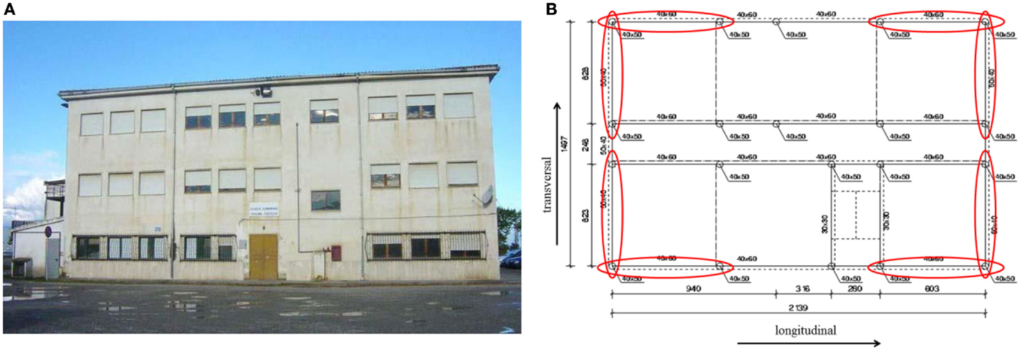
Figure 1. Front view (A) and plan view (B) of the case study building with indication of the bays in which the dampers are placed.
The numerical simulations have been developed using the software SAP 2000 NL v16. A group of seven artificial records have been generated by SIMQKE (Vanmarcke et al., 1990) in order to match the design spectrum according to the Italian building code (NTC, 2008) (Figure 2).
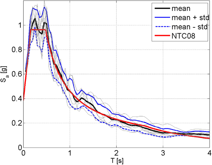
Figure 2. Response spectra (corresponding to 5% viscous damping) of the seven artificial records.
The seismic weight of the building Wtot is approximately equal to 17,240 kN, while the first three periods (two mainly translational and one mainly rotational) of the naked frame structure (without the non-structural masonry infills) are equal to 0.8, 0.45, and 0.52 s, respectively.
The retrofitting strategy adopted here is based on the insertion of inter-storey viscous dampers. In detail, four inter-storey viscous dampers are supposed to be located at each floor along both the longitudinal and the transversal directions, as shown in the plan view of the building (Figure 1). The damper system is therefore composed of 24 viscous dampers and is designed according to both the direct five-step procedure and the MCEER procedure (see next section). For the final verification of the effectiveness of the designed damper system (i.e., Step 5 of the procedure), three numerical models have been developed:
• the naked structure, i.e., the building structure without added dampers (UND model);
• the building structure equipped with inter-storey linear viscous dampers (D-L model);
• the building structure equipped with inter-storey non-linear viscous dampers (D-NL model).
It has to be noted that in all models, beams and columns are modeled through linear-elastic frame elements. In the D-L and D-NL model, the viscous dampers are modeled as damper-exponential link element with value of the damper exponent equal to 1.0 (i.e., linear damper) and 0.15, respectively. The linear and non-linear damping coefficients are evaluated according to both the direct five-step procedure and the MCEER procedure (see Tables 1 and 2). A 3D view of the D-NL SAP model is shown in Figure 3.
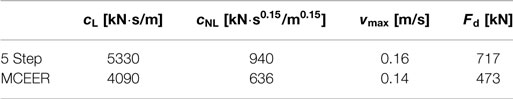
Table 1. Non-linear dampers characteristics along the X direction.
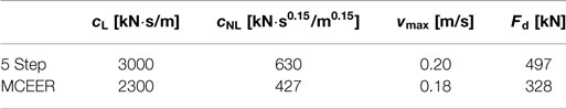
Table 2. Non-linear dampers characteristics along the Y direction.
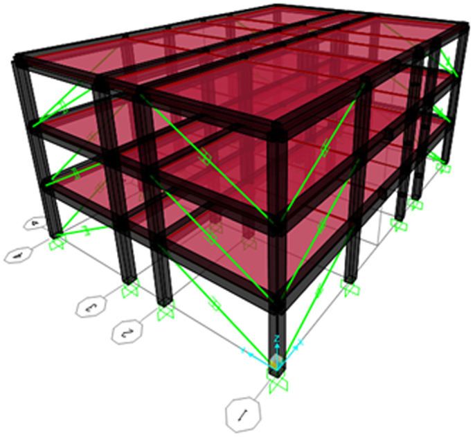
Figure 3. SAP 2000 model of the structure equipped with inter-storey viscous dampers.
The Design of the Added Viscous Dampers
A target damping ratio has been chosen in order to design the system of added viscous dampers. The dampers are sized assuming a fundamental period T1 = 0.45 s and a spectral acceleration = 0.52 g along the X direction and a fundamental period T1 = 0.8 s and a spectral acceleration = 0.36 g along the Y directions. A damping exponent α = 0.15 is assumed. The design is performed according to both the direct five-step procedure and the MCEER procedure assuming a linear deformed shape and equal dampers at all storeys. The results of the two design procedures are summarized in Tables 1 and 2, which give the values of the linear and non-linear damping coefficients (cL and cNL), the expected working velocities (vmax) and maximum damper force (Fd).
Verification through Non-Linear Time-History Analyses
The averages (over the seven accelerograms) of the maximum values of the base shear, as obtained for the UND, the D-L, and the D-NL models are reported in Tables 3 and 4 for the damping systems designed according to the five-step procedure and the MCEER procedure, respectively. Also, the damping reduction factor of the base shear is reported. Note that, for a target damping ratio of , the widely used formulation by Bommer et al. (2000) leads to .
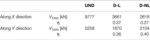
Table 3. Reduction in the base shear (direct five-step procedure).

Table 4. Reduction in the base shear (MCEER procedure).
First, it can be noted that both the design procedures are conservative provided that the obtained reductions of the base shear are larger than the expected ones. As expected, the five-step procedure is more conservative than the MCEER procedure, especially in the non-linear case. This is again an expected result provided that in the non-linear case both the discrepancies in the evaluation of the linear damping coefficients and the inter-storey velocities are present (see Eqs 9 and 10).
Tables 5 and 6 compare the averages (over the seven accelerograms) of the maximum values of the damper forces with the corresponding predictions according to the direct five-step procedure and the MCEER procedure, respectively. Again, as expected, the forces derived with the direct five-step procedure-based FE model are larger than the ones obtained with the MCEER-based FE model. The average relative errors in the estimation of the damper forces according to the five-step procedure are of the order of 15–20%, while the average relative errors given by the MCEER procedure are around 5–10%. However, it has to be noted that, due to the high non-linear constitutive behavior of the dampers (damping exponent of 0.15), a relative small error in the estimation of the maximum damper forces would result in larger errors in the estimation of the maximum strokes and displacements, as shown by the results of the linear time-history simulations summarized in Tables 7 and 8 in terms of maximum (average values over the seven accelerograms) damper forces in the linear dampers (relative errors around 50 and 30% for the direct five-step procedure and the MCEER procedure, respectively). The level of accuracy in the estimation of the structural response can be improved in the verification phase, i.e., in the time-history analyses of the Step 5. Otherwise, in the design phase, it can be improved by employing the original formulation of the five-step procedure, at the cost of additional numerical simulations required to evaluate the working velocities of the linear dampers (Silvestri et al., 2010). For instance, Table 9 provides a comparison between the original five-step procedure and the direct five-step procedure in terms of the reduction of the base shear. It can be noted that the original five-step procedure leads to similar results in terms of base shear reduction (slightly less conservative) with respect to the MCEER procedure.
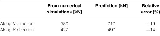
Table 5. Maximum damper forces in the non-linear dampers (direct five-step procedure).
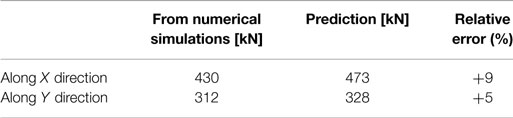
Table 6. Maximum damper forces in the non-linear dampers (MCEER procedure).
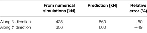
Table 7. Maximum damper forces in the linear dampers (direct five-step procedure).

Table 8. Maximum damper forces in the linear dampers (according to the MCEER procedure).
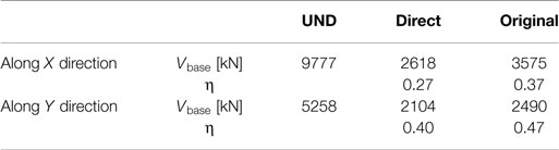
Table 9. Reduction in the base shear (original vs. direct five-step procedure).
Conclusion
In this paper, the original five-step procedure for the seismic design of viscous dampers to be added in multi-storey framed structures, as proposed by Silvestri et al. (2010), is further simplified leading to a direct (i.e., fully analytical) procedure. The new developments allow to carry out the preliminary design with analytical formulas only, therefore not requiring the development of the linear seismic time-history analyses required by the original procedure to evaluate the working velocities of the dampers. First, it is noted that the direct five-step procedure leads to a more conservative design of the added dampers with respect to the MCEER procedure. In detail for a one-storey building, the two design procedures lead to the same design, while as the storey number approach to infinite the linear damping coefficient calculated according to the direct five-step procedure approach to 1.5 the corresponding one calculated according to the MCEER procedure, and the damper inter-storey velocities calculated according to the direct five-step procedure approach to 1.33 the corresponding one calculated according to the MCEER procedure.
Finally, the direct five-step procedure has been applied to design added viscous dampers to be inserted in a real building, i.e., a RC school building located in southern Italy. It is confirmed that the direct procedure, besides allowing an easy and quick identification of the mechanical characteristics of the viscous dampers, leads to a conservative achievement of the target performances (i.e., reduction in seismic response with respect to the reference structure with no additional damping system) and to a quite good estimation (from an engineering point of view) of the damper forces, even though less accurate than the MCEER procedure. With regard to the strokes and deformations, an improved estimate can be obtained in the verification time-history analyses of Step 5 or, in the design phase, using the original five-step procedure (or alternatively the MCEER procedure).
Conflict of Interest Statement
The authors declare that the research was conducted in the absence of any commercial or financial relationships that could be construed as a potential conflict of interest.
Acknowledgments
Financial support from the Department of Civil Protection (DPC-Reluis 2014–2018 Grant – Research line 6: “Seismic isolation and dissipation”) is gratefully acknowledged.
References
Adachi, F., Fujita, K., Tsuji, M., and Takewaki, I. (2013). Importance of inter-storey velocity on optimal along-height allocation of viscous oil dampers in super high-rise buildings. Eng. Struct. 56, 489–500. doi:10.1016/j.engstruct.2013.05.036
American Society of Civil Engineers (ASCE). (1999). Minimum Design Loads for Buildings and Other Structures, ASCE 7-98. Reston, VA: ASCE.
Bommer, J. J., Elnashai, A. S., and Weir, A. G. (2000). “Compatible acceleration and displacement spectra for seismic design codes,” in Proceedings of the 12th World Conference on Earthquake Engineering (Auckland).
Chopra, A. K. (1995). Dynamics of Structures. Theory and Applications to Earthquake Engineering. Upper Saddle River, NJ: Prentice-Hall.
Christopoulos, C., and Filiatrault, A. (2006). Principles of Passive Supplemental Damping and Seismic Isolation. Pavia: IUSS Press.
Constantinou, M. C., Soong, T. T., and Dargush, G. F. (1998). Passive Energy Dissipation Systems for Structural Design and Retrofit, Monograph No. 1. Buffalo, NY: Multidisciplinary Center for Earthquake Engineering Research.
Constantinou, M. C., and Symans, M. D. (1992). Experimental and Analytical Investigation of Seismic Response of Structures with Supplemental Fluid Viscous Dampers. NCEER-92-0032. Technical Report. Buffalo, NY: National Center for Earthquake Engineering Research.
Constantinou, M. C., and Symans, M. D. (1993). Seismic response of structures with supplemental damping. Struct. Des. Tall Build. 2, 77–92. doi:10.1002/tal.4320020202
Constantinou, M. C., and Tadjbakhsh, I. G. (1983). Optimum design of a first story damping system. Comput. Struct. 17, 305–310. doi:10.1016/0045-7949(83)90019-6
Diotallevi, P. P., Landi, L., and Dellavalle, A. (2012). A methodology for the direct assessment of the damping ratio of structures equipped with nonlinear viscous dampers. J. Earthq. Eng. 16, 350–373. doi:10.1080/13632469.2011.618521
Hart, G. C., and Wong, K. (2000). Structural Dynamics for Structural Engineers. New York, NY: Wiley.
Hwang, J. S., Lin, W. C., and Wu, N. J. (2013). Comparison of distribution methods for viscous damping coefficients to buildings. Struct. Infrastruct. Eng. 9, 28–41. doi:10.1080/15732479.2010.513713
Landi, L., Diotallevi, P. P., and Castellari, G. (2013). On the design of viscous dampers for the rehabilitation of plan-asymmetric buildings. J. Earthq. Eng. 17, 1141–1161. doi:10.1080/13632469.2013.804893
Landi, L., Lucchi, S., and Diotallevi, P. P. (2014a). A procedure for the direct determination of the required supplemental damping for the seismic retrofit with viscous dampers. Eng. Struct. 71, 137–149. doi:10.1016/j.engstruct.2014.04.025
Landi, L., Fabbri, O., and Diotallevi, P. P. (2014b). A two-step direct method for estimating the seismic response of nonlinear structures equipped with nonlinear viscous dampers. Earthq. Eng. Struct. Dyn. 43, 1641–1659. doi:10.1002/eqe.2415
Levy, R., and Lavan, O. (2006). Fully stressed design of passive controllers in framed structures for seismic loadings. Struct. Multidiscip. Optim. 32, 485–498. doi:10.1007/s00158-005-0558-5
Lopez Garcia, D. (2001). A simple method for the design of optimal damper configurations in MDOF structures. Earthq. Spectra 17, 387–398. doi:10.1193/1.1586180
Mazza, F., and Vulcano, A. (2014). Equivalent viscous damping for displacement-based seismic design of hysteretic damped braces for retrofitting framed buildings. Bull. Earthquake Eng. 12, 2797–2819. doi:10.1007/s10518-014-9601-5
Norme Tecniche per le Costruzioni (NTC). (2008). Italian building code, adopted with D.M. 14/01/2008, Published on S.O. n. 30 G.U. n. 29.
Occhiuzzi, A. (2009). Additional viscous dampers for civil structures: analysis of design methods based on effective evaluation of modal damping ratios. Eng. Struct. 31, 1093–1101. doi:10.1016/j.engstruct.2009.01.006
Palermo, M., Muscio, S., Silvestri, S., Landi, L., and Trombetti, T. (2013a). On the dimensioning of viscous dampers for the mitigation of the earthquake-induced effects in moment-resisting frame structures. Bull. Earthq. Eng. 11, 2429–2446. doi:10.1007/s10518-013-9474-z
Palermo, M., Silvestri, S., Trombetti, T., and Landi, L. (2013b). Force reduction factor for building structures equipped with added viscous dampers. Bull. Earthq. Eng. 11, 1661–1681. doi:10.1007/s10518-013-9458-z
Peckan, G., Mander, J. B., and Chen, S. S. (1999). Fundamental considerations for the design of non-linear viscous dampers. Earthq. Eng. Struct. Dyn. 28, 1405–1425. doi:10.1002/(SICI)1096-9845(199911)28:11<1405::AID-EQE875>3.3.CO;2-1
Ramirez, O. M., Constantinou, M. C., Kircher, C. A., Whittaker, A. S., Johnson, M. W., and Gomez, J. D. (2000). Development and Evaluation of Simplified Procedures for Analysis and Design of Buildings with Passive Energy Dissipation Systems. MCEER Report 00-0010. Buffalo, NY: Multidisciplinary Center for Earthquake Engineering Research, University at Buffalo, State University of New York.
Shukla, A. K., and Datta, T. K. (1999). Optimal use of viscoelastic dampers in building frames for seismic force. J. Struct. Eng. 125, 401–409. doi:10.1061/(ASCE)0733-9445(1999)125:4(401)
Silvestri, S., Gasparini, G., and Trombetti, T. (2010). A five-step procedure for the dimensioning of viscous dampers to be inserted in building structures. J. Earthq. Eng. 14, 417–447. doi:10.1080/13632460903093891
Silvestri, S., Gasparini, G., and Trombetti, T. (2011). Seismic design of a precast r. c. structure equipped with viscous dampers. Earthq. Struct. 2, 297–321. doi:10.12989/eas.2011.2.3.297
Silvestri, S., Palermo, M., Landi, L., Gasparini, G., and Trombetti, T. (2014). “Estimation of maximum damper forces in shear-type buildings subjected to seismic input,” in Proceedings of the 2nd European Conference on Earthquake Engineering and Seismology (Istanbul), 24–29.
Silvestri, S., and Trombetti, T. (2007). Physical and numerical approaches for the optimal insertion of seismic viscous dampers in shear-type structures. J. Earthq. Eng. 11, 787–828. doi:10.1080/13632460601034155
Singh, M. P., and Moreschi, L. M. (2002). Optimal placement of dampers for passive response control. Earthq. Eng. Struct. Dyn. 31, 955–976. doi:10.1002/eqe.132.abs
Soong, T. T., and Dargush, G. F. (1997). Passive Energy Dissipation Systems in Structural Engineering. Chichester: Wiley.
Sorace, S., and Terenzi, G. (2014). Motion control-based seismic retrofit solutions for a R/C school building designed with earlier Technical Standards. Bull. Earthquake Eng. 12, 2723–2744. doi:10.1007/s10518-014-9616-y
Takewaki, I. (1997). Optimal damper placement for minimum transfer functions. Earthq. Eng. Struct. Dyn. 26, 1113–1124. doi:10.1002/(SICI)1096-9845(199711)26:11<1113::AID-EQE696>3.0.CO;2-X
Takewaki, I. (2000). Optimal damper placement for critical excitation. Prob. Eng. Mech. 15, 317–325. doi:10.1016/S0266-8920(99)00033-8
Takewaki, I. (2009). Building Control with Passive Dampers: Optimal Performance-Based Design for Earthquakes. Singapore: Wiley.
Trombetti, T., and Silvestri, S. (2004). Added viscous dampers in shear-type structures: the effectiveness of mass proportional damping. J. Earthq. Eng. 8, 275–313. doi:10.1080/13632460409350490
Trombetti, T., and Silvestri, S. (2006). On the modal damping ratios of shear-type structures equipped with Rayleigh damping systems. J. Sound Vib. 292, 21–58. doi:10.1016/j.jsv.2005.07.023
Trombetti, T., and Silvestri, S. (2007). Novel schemes for inserting seismic dampers in shear-type systems based upon the mass proportional component of the Rayleigh damping matrix. J. Sound Vib. 302, 486–526. doi:10.1016/j.jsv.2006.11.030
Tubaldi, E., Ragni, L., and Dall’Asta, A. (2014). Probabilistic seismic response assessment of linear systems equipped with nonlinear viscous dampers. Earthq. Eng. Struct. Dyn. 44, 101–120. doi:10.1002/eqe.2461
Keywords: peak inter-storey velocities, added viscous dampers, design procedure
Citation: Trombetti T, Palermo M, Dib A, Gasparini G, Silvestri S and Landi L (2015) Application of a direct procedure for the seismic retrofit of a R/C school building equipped with viscous dampers. Front. Built Environ. 1:14. doi: 10.3389/fbuil.2015.00014
Received: 10 March 2015; Accepted: 31 August 2015;
Published: 28 September 2015
Edited by:
Oren Lavan, Technion – Israel Institute of Technology, IsraelReviewed by:
Izuru Takewaki, Kyoto University, JapanShinta Yoshitomi, Ritsumeikan University, Japan
Copyright: © 2015 Trombetti, Palermo, Dib, Gasparini, Silvestri and Landi. This is an open-access article distributed under the terms of the Creative Commons Attribution License (CC BY). The use, distribution or reproduction in other forums is permitted, provided the original author(s) or licensor are credited and that the original publication in this journal is cited, in accordance with accepted academic practice. No use, distribution or reproduction is permitted which does not comply with these terms.
*Correspondence: Michele Palermo, Department of Civil, Chemical, Environmental, and Materials Engineering, University of Bologna, Viale del Risorgimento 2, 40136 Bologna, Italy,bWljaGVsZS5wYWxlcm1vN0B1bmliby5pdA==