 Nefize Shaban
 Alp Caner
- Middle East Technical University, Ankara, Turkey
The increasingly demanding performance requirements trigger the development of new devices to eliminate the limitations concerning the post-earthquake performance of available seismic protection systems. The prerequisite for economical earthquake-resistant bridges is the structures’ capacity to absorb and dissipate a large amount of seismic energy. A widely considered strategy for enhancing this capacity is through the use of passive energy dissipation systems for seismic protection of structures. It has been known that majority of the available energy dissipation systems are non-usable after a major earthquake, which increases the risk of collapse during an aftershock. The focus of the current study is given to introduce a new type of passive energy dissipation device with a pending patent that is testified to have an improved energy dissipation capacity without suffering any damage while absorbing energy. Thus, the proposed damper does not require an immediate expensive replacement and keeps its operational capabilities and effectiveness during aftershocks. The paper presents the dynamic performance tests of the first full-scale prototype of the damper, that eventually prove it to be a promising design with an improved energy dissipation capacity and stable behavior during and after the dynamic event.
Introduction
The history of damaging earthquakes worldwide evidences the vulnerability of humanity to the forces of nature. The tremendous amount of energy released during an earthquake can produce extreme damages even in an advanced industrial nation. Thereby, one of the major current challenges in structural engineering is focused on mitigation of hazardous earthquake effects which requires development of innovative design concepts and new techniques.
Traditional seismic design practice has been based on providing a combination of strength and ductility to resist the imposed earthquake loading (Elnashai and Di Sarno, 2008). A reduction of seismic forces below the elastic level can be applied in design provided that an inelastic behavior in a properly designed structure will supply that structure with sufficient energy dissipation capacity so that it can sustain a severe earthquake without collapse. This inelastic action is usually designed to concentrate in conscientiously detailed critical regions of the bridge, usually in the end zones of piers. The dissipation of substantial amount of energy, realized by the inelastic action in these regions, is achieved at the expenses of significant damage to the structural member. Thereby, a repeated inelastic cycling will result in degradation in the hysteretic behavior of the critical regions.
To overcome these limitations inherent in the philosophy of conventional seismic design, innovative concepts of structural protection have been developed and subsequently implemented. Modern systems for structural control can be grouped into three categories: (1) seismic isolation, (2) semi-active and active control, and (3) passive energy dissipation (Soong and Dargush, 1997; Housner et al., 1999; Symans and Constantinou, 1999; Soong and Spencer, 2002; Symans et al., 2008).
The concept of seismic isolation has been developed into a practical technology widely implemented in seismically active areas. Its basic principle is set on uncoupling the structure from the damaging action of an earthquake, thereby, reducing the forces transmitted to the structure. Typically, the isolation system employs structural elements with low horizontal stiffness usually placed at the foundation level. Thus, the structure’s fundamental frequency is reduced, and its corresponding dynamic mode involves displacement only at the isolation level. The higher modes do not contribute to the structural motion and, consequently, do not transfer energy to the structure. The structural protection is achieved not by absorption but rather through deflection of the input energy using the dynamics of the system. The net result is a decrease in the energy dissipation demand on the structure, expressed in terms of reduction in interstory drifts and floor accelerations, while the displacement is concentrated in the isolation system. The concept is applicable and effective both for buildings and bridges (Soong and Dargush, 1997; Housner et al., 1999; Symans et al., 2008; Di Sarno, 2013).
Active and semi-active control systems reduce the structural response by means of controllers, processing response information in real time, integrated with force generators that apply counteracting control forces. In the active control methods, the counteracting forces are applied by actuators and provided by a large power source, while in the semi-active control systems such forces are generated by reactive devices with controllable dynamic (damping and/or stiffness) properties. The power supply for semi-active control devices is typically orders of magnitude smaller compared with the one required for active control methods. Usually, the large control forces required by these methods can limit their practical application, especially for large and massive structures (Symans and Constantinou, 1999).
Contrary to semi-active and active systems, passive energy dissipation devices do not require an external supply of power. Furthermore, compared to seismic isolation, these devices can provide an effective protection against both earthquake and wind loads. The exceptional highlight should be made for bridges with high piers and long-period long-duration earthquake ground motions, the set of conditions that make the seismic base isolation inadequate and insufficient and the active control methods unaffordable. Thus, incorporation of passive energy dissipation devices comes out to be a modern and innovative approach for economical and safer structural design. Most commonly implemented passive energy dissipation systems include viscous fluid dampers, viscoelastic solid dampers, friction dampers, and metallic dampers. More rarely applied are tuned mass dampers, re-centering dampers, and phase transformation dampers. These dampers purely dissipate energy during structural movements to maintain movements at permissible levels.
Passive energy dissipation devices can be divided into three groups: (1) rate-dependent devices, (2) rate-independent devices, and (3) others. The force output of rate-dependent devices is directly related to the rate of change of displacement across the damper. Representatives of this group are viscoelastic fluid dampers and viscoelastic solid dampers. Viscoelastic solid dampers affect the structural stiffness and thus, the fundamental natural frequency, while viscoelastic fluid dampers do not. The latter provide a reduction in ductility demand and structural response as a result of supplemental damping only. Rate-independent systems include dampers whose force output is not related with the rate of change of displacement across the damper. Metallic and friction dampers come under this category. Metallic dampers develop a smooth hysteretic behavior, while friction dampers follow an essentially bilinear hysteretic pattern with very high initial stiffness (Soong and Dargush, 1997; Housner et al., 1999; Soong and Spencer, 2002; Symans et al., 2008). The reduction in ductility demand is provided both through increased system stiffness and hysteretic energy dissipation. The effective performance of a certain passive energy dissipation device depends on the peculiar features of the original structure, the properties of the implemented device, and the characteristics of the ground motion. Considering the large variability in each of these parameters, a comprehensive series of analyses is a requisite to conclude about the particular passive energy dissipation system, which is appropriate for a given case.
Along with all their advantages, all the widely implemented dampers have some limitations and drawbacks that need also be considered, while deciding on the proper response control strategy for a given structure. Viscous fluid dampers are susceptible to fluid seal leakage, which raises a reliability concern. Viscoelastic solid dampers exhibit limited deformation capacity, their properties are frequency and temperature-dependent, and again reliability is questioned by possible debonding and tearing of viscoelastic material. Metallic dampers are to be damaged during an earthquake and thus require replacement. Friction dampers also cause a reliability concern due to the sliding interface conditions changing with time. These dampers may as well excite higher modes in structural response and exhibit stick-slip behavioral problem (Symans et al., 2008). Both metallic and friction dampers increase the system stiffness, which adds to the base shear which would need to be accommodated in the design of the structure and consequently gives reflection to foundation costs. The implementation of viscous fluid, metallic, and friction dampers will lead to permanent displacements after a possible dynamic action if no restoring mechanism is provided. As far as effective system integration is concerned, the described devices are all expedient to reduce the potential structural damage but the structural performance during and after the event need to be extensively investigated to proportion the benefits and the expenses to achieve them.
This analysis challenges further developments and advanced engineering design solutions in the area of passive structural control to aim for an improved performance. The focus of the currently presented research is developing a new damper that can re-center the structure after a possible dynamic event and dissipate energy without suffering any damage. Thereby, it does not require an immediate expensive replacement and the device-integrated structure can be protected against possible aftershocks, being intact and ready for immediate use after the event. As to the long-term operation, the invariability of inherent properties provides the required reliability and stable behavior. The dynamic properties of the device are easily controllable, making it adjustable for different design solutions. Also, the newly proposed system is intended to have a configuration simple enough to facilitate easy and functional implementation both for new construction and retrofitting, requiring minimal interventions and disruptions to bridge functionality. The device can also be engineered to be used in building structures. The simple design and operational mechanism take up the challenge of behavior prediction and reliability, being designed on the principle of “as simple as possible but not simpler than it should.” As a result, the energy dissipation device with a pending patent has an innovative design, advanced performance, and enhanced effectiveness.
The first prototype of the device has been produced and its dynamic performance tests conducted at the Structural Mechanics Laboratory of Civil Engineering Department at Middle East Technical University. The part of the research presented in this paper covers the device description, test setup, and test results obtained from dynamic performance tests of the first full-scale prototype.
Device Description
The new type of damper introduced in the current paper has the ability to re-center the structure, does not suffer any damage while dissipating energy, thus does not need a replacement after a possible event and keeps its operational capability during following excitations and aftershocks. It has a simple design which allows for easy application without any major intervention in the integrity of the existing structural system. All these features can be achieved by the proper combination of material, configuration, design, and delicate prediction of working mechanism.
The damper assembly has two main subassemblies: an energy dissipation unit (ED unit) and a driving mechanism. The ED unit is composed of two symmetrically placed elastomer blocks whose mechanical and dynamic properties can be tuned to the pre-defined performance targets. These blocks can be either elastomer, laminated rubber, lead rubber, or ball rubber composite. The ED unit dissipates energy and at the same time provides the re-centering force due to the rubber inherent properties. In doing so, it can sustain many cycles of reversed loading without getting any damage, a certification for a stable and reliable hysteretic behavior, as well as effective post-event protection.
The driving mechanism amplifies the interstory displacement and transfers it to the ED unit. Its rate of amplification can be easily adjusted to given performance targets. The mechanism is made of steel and designed so as to remain elastic all through a possible dynamic event. The integration of this mechanism enhances the device effectiveness both in terms of energy dissipation and re-centering capability.
The ED unit of the first prototype is composed of two symmetrically placed laminated rubber blocks (colored in yellow in Figure 1) placed on steel mounts (colored in green). The amplification rate of the driving mechanism is 2 and the device displacement capacity is 45 mm, corresponding to 1.5% interstory drift of a 3 m-high frame. The solid model of the device full-scale prototype is given in Figure 1 and the produced prototype in Figure 2.
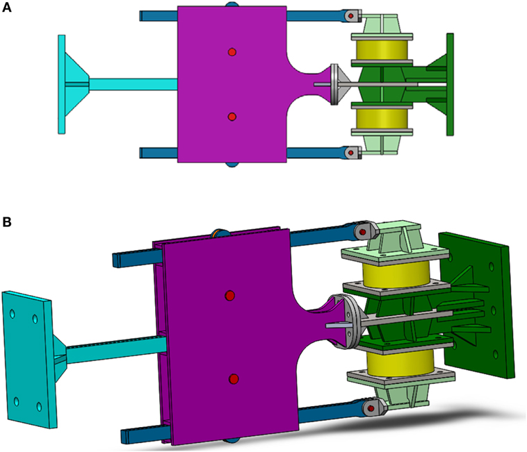
Figure 1. Solid model of the new damper (A) 2D and (B) 3D.
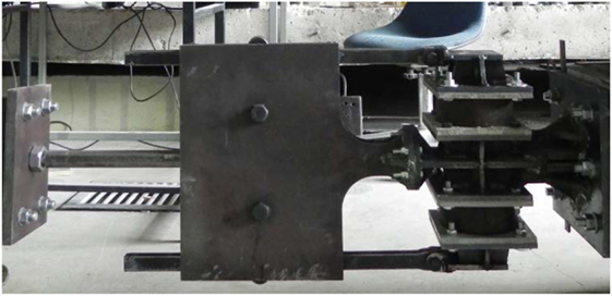
Figure 2. First full-scale prototype produced.
The uni-directional device can be used to limit the structural displacements of the bridge superstructure in two orthogonal directions. The device can be mounted at the expansion joints connecting superstructure segments to each other, or connecting the superstructure to the substructure as recommended in the seismic retrofit manual for bridges (Buckle et al., 2006). The mounting detail of the device shall be engineered to allow out-of-plane movements. Providing ball joints at either end of the unit can be one simple solution. The structure and mounting brackets must be designed to have no fatigue problems, while resisting drag forces.
Test Setup
In parallel with the prototype production, the test setup is being installed at the Structural Mechanics Laboratory. The test setup design drawings are presented in Figure 3.
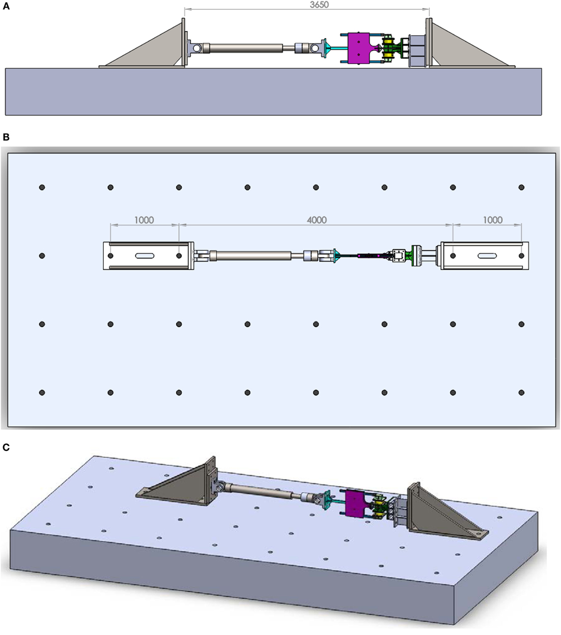
Figure 3. Test setup design drawings (A) front view, (B) top view, and (C) 3D.
At first, two steel supports are fixed to the laboratory’s rigid floor by pre-stressed steel studs. At each support, two 1 m apart steel studs are used, each of them applying a pre-stress force of 225 kN. The completion of the installation is as shown in Figure 4.
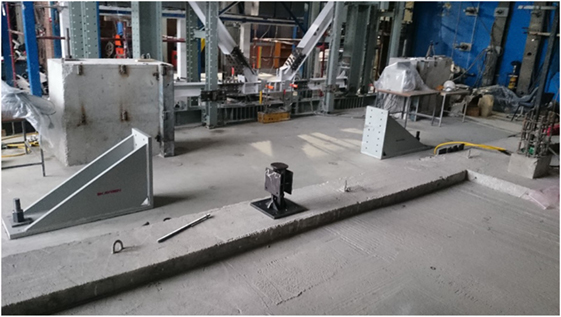
Figure 4. Steel supports of the test setup fixed to the laboratory rigid floor.
One of the supports is used for fixing the hydraulic actuator to be used in the dynamic performance tests, while the other one is used later for supporting the prototype. The hydraulic actuator (Figure 5) to be used for dynamic performance tests has a force capacity of 250 kN, a ±15 cm stroke and can apply a velocity up to 350 mm/s.
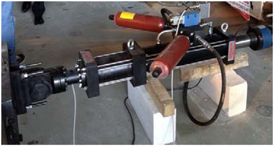
Figure 5. Hydraulic actuator to apply the dynamic loading.
Test Schedule
After the ED unit elastomeric blocks are produced, their mechanical properties are determined by double shear tests performed on elastomeric bearing test machine at Structural Mechanics Laboratory (Figure 6).
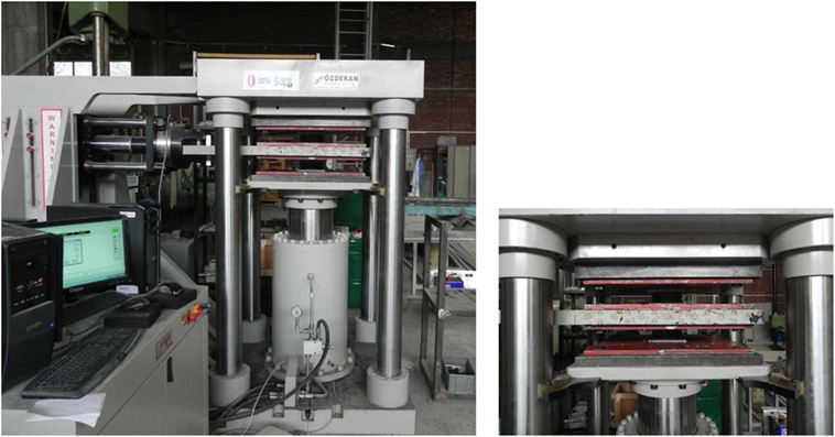
Figure 6. Double shear tests.
The hysteresis loop obtained from double shear tests under 100% strain is presented in Figure 7.
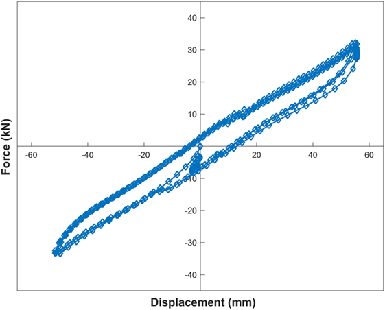
Figure 7. Hysteresis loop under 100% strain for two laminated rubber blocks.
The tested ED unit blocks are installed on the steel mounts and connected to the already produced driving mechanism, and the assembled device prototype is mounted on the previously prepared test setup ready for dynamic performance tests.
The performed dynamic tests are based on displacement control with a sinusoidal signal. Many sets of dynamic tests are performed to sweep a large interval of amplitude, frequency, and velocity. The amplitude ranges from 5 to 45 mm with an increment of 3 mm, the frequency from 0.1 to 5.0 Hz with an increment of 0.1 Hz, and the velocity from 1 to 350 mm/s.
Test Results
The hysteresis loops obtained under a sinusoidal displacement of 0.5 Hz frequency and different amplitudes are given in Figure 8. It is seen that the loops follow the same behavior pattern and prove a stable performance. Also, the large area enclosed by the hysteresis loops indicates a substantial energy dissipation capacity larger than many of the device’s viscoelastic peers and competitors. Table 1 summarizes the effective equivalent viscous damping ratios calculated for the hysteresis loops of Figure 8. These data underlines the strong influence of displacement amplitude on the device effective equivalent viscous damping ratio. The maximum effective equivalent viscous damping ratio of 37.3% is observed for 15 mm displacement amplitude corresponding to 60% strain in the viscoelastic part of the ED unit. This finding has the limitations of frequency (0.5 Hz in this case) and the pre-defined geometric and mechanical properties of the ED unit, which may separately or in interaction change the behavior parameters (the effective equivalent viscous damping ratio magnitude and its corresponding displacement amplitude, etc.) of the device. This relation observed in the performed tests, will be more comprehensively investigated through the ongoing series of prototype tests along with the interaction between different parameters to come to a final conclusion. As for the first prototype tests, no damage and no change in behavior pattern was observed after about 1000 successive cycles performed in total. Therefore, the device has been proven to provide an enhanced energy dissipation without suffering any damage and while keeping a stable behavior, all findings being valid for the prescribed ranges of test parameters.
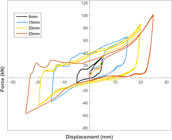
Figure 8. Hysteresis loops under 0.5 Hz frequency and different amplitudes of the sinusoidal excitation.
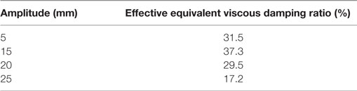
Table 1. Effective equivalent viscous damping ratios under 0.5 Hz frequency and different amplitudes of the sinusoidal excitation.
The test observations further reveal that the design of the ED unit is of primary importance for the device overall behavior. Therefore, the research is planned to continue with a comprehensive analysis of critical parameters performing dynamic tests of prototypes integrating ED units of different material and geometric properties.
Conclusion
A new energy dissipation device with a pending patent has been introduced. The first full-scale prototype of the proposed device has been produced and tested. The dynamic performance tests of the prototype have proven it to be a promising device that may substantially reduce the energy dissipation demand on structural members (with an observed maximum effective equivalent viscous damping ratio of 37.3% under 0.5 Hz frequency of harmonic displacement excitation). At the same time, within the ranges of the test parameters, the damper does not get damaged and manifests a stable behavior all through and after the dynamic action providing an effective aftershock protection. This conclusion has motivated a furthermore comprehensive investigation and improvement of the device performance.
For the following tests, the ranges of the testing parameters will be further enhanced to capture the peculiarities of various dynamic actions and investigate extensively the sensitivity of the device performance to different variables as well as the interaction between them.
Author Contributions
NS (70% – research, test, and report), AC (30% research and report).
Conflict of Interest Statement
The authors declare that the research was conducted in the absence of any commercial or financial relationships that could be construed as a potential conflict of interest.
Acknowledgments
The authors would like to thank TÜBİTAK 2215 program for the financial support to the presented research.
References
Buckle, I., Friedland, I., Mander, J., Martin, G., Nutt, R., and Power, M. (2006). Seismic Retrofitting Manual for Highway Structures: Part I Bridges. Report No: FHWA-HRT-06-032. VA, USA: U.S. Department of Transportation FHWA.
Elnashai, A. S., and Di Sarno, L. (2008). Fundamentals of Earthquake Engineering. Chichester, UK: John Wiley & Sons Ltd.
Housner, G. W., Bergman, L. A., Caughey, T. K., Chassiakos, A. G., Claus, R. O., Masri, S. F., et al. (1999). Structural control: past, present and future. J. Eng. Mechanics 123, 899–905.
Soong, T. T., and Dargush, G. F. (1997). Passive Energy Dissipation Systems in Structural Engineering. Chichester, UK: John Wiley & Sons Ltd.
Soong, T. T., and Spencer, B. F. (2002). Supplemental energy dissipation: state-of-the-art and State-of-the-practice. Eng. Struct. 24, 243–259. doi: 10.1016/S0141-0296(01)00092-X
Symans, M. D., Charney, F. A., Whittaker, A. S., Constantinou, M. C., Kircher, C. A., Johnson, M. W., et al. (2008). Energy dissipation systems for seismic applications: current practice and recent developments. J. Struct. Eng. 134, 3–21. doi:10.1061/(ASCE)0733-9445(2008)134:1(3)
Keywords: seismic protection, energy dissipation device, improved effectiveness, post-earthquake performance, bridge
Citation: Shaban N and Caner A (2016) Prototype Testing of a New Passive Energy Dissipation Device for Seismic Retrofit of Bridges. Front. Built Environ. 2:23. doi: 10.3389/fbuil.2016.00023
Received: 16 June 2016; Accepted: 16 September 2016;
Published: 29 September 2016
Edited by:
Bruno Briseghella, Fuzhou University, ChinaReviewed by:
Anastasios Sextos, Aristotle University of Thessaloniki, Greece; University of Bristol, UKLuigi Di Sarno, University of Sannio, Italy
Copyright: © 2016 Shaban and Caner. This is an open-access article distributed under the terms of the Creative Commons Attribution License (CC BY). The use, distribution or reproduction in other forums is permitted, provided the original author(s) or licensor are credited and that the original publication in this journal is cited, in accordance with accepted academic practice. No use, distribution or reproduction is permitted which does not comply with these terms.
*Correspondence: Alp Caner, YWNhbmVyQG1ldHUuZWR1LnRy