 Charis J. Gantes
 Vasileios E. Melissianos
- Institute of Steel Structures, School of Civil Engineering, National Technical University of Athens, Athens, Greece
Buried steel fuel pipelines are critical lifelines for the society and the economy but are very vulnerable to earthquake-induced ground failure. Traversing seismic areas inevitably results in several pipe-fault crossings. Fault rupture forces a buried pipeline to undergo deformations that could be substantial and heavily endanger its integrity. Due to the grave consequences of a potential pipe failure, mitigating measures are commonly applied at pipe-fault crossings to reduce the effects of a potential fault activation. In this paper, a comparative review of several measures that are used in practice or have been proposed in the technical literature is presented. Numerical analyses are then carried out to compare the effectiveness of commonly used measures and to extract conclusions regarding their applicability. Results indicate that the most efficient among the evaluated measures are pipe placement within culverts and use of flexible joints. Trench backfilling with pumice is a moderately effective measure in terms of pipe protection, while steel grade upgrade, wall thickness increase, and pipe wrapping with geotextile are found to be insufficient protection methods.
Introduction
Buried steel pipelines are the main onshore transportation means of oil and gas within a region and across borders; their contribution to the society and the economy is thus very significant. The construction of an onshore buried pipeline commonly consists of the following stages: (i) pre-construction survey of the field, (ii) cleaning and grading of the construction site, (iii) trench excavation, (iv) transportation of pipe segments to the construction field and pipe stringing and bending, (v) welding and inspection of pipe segments and pipe coating, (vi) pipe lowering into the trench, (vii) hydraulic testing of the pipe, (viii) trench backfill, and (ix) restoration of the construction site.
Pipes are hazardous structures as their potential failure may heavily affect the environment, the society, and the economy in terms of fuel loss, pollution, flow interruption, and the necessity for repair and restoration. Earthquake-induced actions causing permanent ground displacements, such as landslides, fault rupture, liquefaction-induced lateral spreading, may significantly endanger the pipe integrity. In case a pipe route traverses seismic areas it is inevitable that several pipe-fault crossings are encountered. A typical pipe-fault crossing is displayed in Figure 1 in plan and section view. The major geometrical properties of such crossing are the pipe-fault crossing angle β and the fault dip angle ψ.
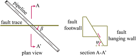
Figure 1. Plan and section view of a typical pipe-fault crossing.
Fault rupture has been identified as the dominant cause of catastrophic pipe failures (O’Rourke and Liu, 2012). When a seismic fault is activated, the pipeline is forced to follow the ground movement, hence developing possibly large deformations and corresponding strains. The main failure modes in such cases are local buckling of the pipe wall and tensile fracture. The former is caused by compression, while the latter by the concentration of tensile strains that mainly endanger the integrity of girth welds between the adjacent pipe segments. The pipeline structural response due to faulting depends on the fault type. Namely, in case of normal faulting, the soil rupture incline is downwards and the pipe is subjected to bending and tension (Figure 2A), while in case of reverse faulting, the soil rupture incline is upwards (both soil blocks are heavily compressed) and the pipe undergoes bending and mainly compression (Figure 2B). Finally, in case of strike-slip faulting, the fault plane is almost vertical and relative block slip take places place along the rupture plane, consequently the pipe is subjected principally to bending and to a smaller extent to either tension or compression (Figure 2C), depending on the pipeline-fault crossing angle (Abdoun et al., 2009).
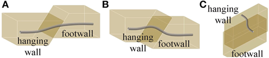
Figure 2. Pipe deformation due to (A) normal, (B) reverse, and (C) strike-slip faulting.
The assessment of pipe behavior due to fault rupture has been of great concern for researchers, engineers, and pipeline operators. Analytical and numerical approaches have been developed for the assessment of the pipe strain-state caused by faulting. Newmark and Hall (1975) were the pioneers in this ongoing effort, presenting a pertinent simplified analytical methodology, considering the pipe as a long cable subjected to relative small displacements caused by a planar fault dividing the ground into two blocks. Then, several researchers extended this analytical procedure by taking into account material non-linearity and non-symmetric conditions regarding the pipe deformation (Kennedy et al., 1977; Kennedy and Kincaid, 1983; Wang and Yeh, 1985; Wang and Wang, 1995; Takada et al., 2001; Karamitros et al., 2007, 2011; Trifonov and Cherniy, 2010, 2012) and the pipe service loads (Zhang et al., 2016b).
The analytical solutions remain useful for the rapid assessment of the pipe behavior in the preliminary design stage. However, securing the pipe resilience necessitates a more rigorous numerical approach. The finite element method (FEM) is used in order to properly take into account the geometrical non-linearity of the problem, as well as the non-linearity of the pipeline material and the surrounding soil. Regarding the numerical modeling of the pipe-fault crossing, two approaches are available.
The first model is that of a Winkler beam, where the pipe is meshed into beam-type finite elements and the surrounding soil with non-linear translational springs in four directions that model the soil resistance due to the pipe movement in the trench (axial, transverse horizontal, and vertical upward and downward). This model is characterized by sufficient reliability, reduced computational cost, and easy implementation for design purposes. However, local buckling and tensile fracture are not directly “captured” by the numerical analysis and must instead be identified by comparing developing strains to code-based limits. This model has been used by researchers [e.g., Ogawa et al. (2004), Joshi et al. (2011), Chaudhary et al. (2013), Uckan et al. (2015), and Liu et al. (2016)] and is also recommended by pertinent structural codes [e.g., American Lifelines Alliance (2005), CEN (2006), and Indian Institute of Technology Kanpur and Gujarat State Disaster Management Authority (2007)].
The second model is the continuum one, where the pipe is modeled with shell elements, the surrounding soil with 3D solid elements, and the pipe–soil interface with contact elements [e.g., Kokavessis and Anagnostidis (2006), Odina and Tan (2009), Vazouras et al. (2010, 2012, 2015), Zhang et al. (2014, 2016a), and Trifonov (2015)]. This model allows the direct investigation of local buckling occurrence and the consideration of trench geometry and detailed fault movement, as well as the use of more detailed soil material laws. Nevertheless, it is associated with significant computational cost (e.g., increased number of degrees-of-freedom, convergence difficulties due to contact elements), and therefore its application for design purposes is very limited.
Pipeline design against permanent ground displacements is carried out in strain terms, considering that the problem is displacement-controlled and taking advantage of pipeline steel ductility. Thus, pertinent structural codes provide upper limits for tensile and compressive strains in order to avoid tensile fracture and local buckling, respectively [e.g., American Lifelines Alliance (2005), CEN (2006), Canadian Standards Association (2007), and Indian Institute of Technology Kanpur and Gujarat State Disaster Management Authority (2007)]. Useful information regarding strain-based design and code-based strain limits can indicatively be found in Gresnigt (1986), Mohr (2003), and Liu et al. (2009). The operable strain limits, after (American Lifelines Alliance, 2005) neglecting the internal pressure as a less favorable situation, are adopted within this study and in particular the tensile strain (εt) limit:
and the compressive strain (εc) limit:
where D is the pipe external diameter, t is the pipe wall thickness, and Dmin is the minimal pipe diameter due to possible ovalization.
The response of a pipe subjected to fault rupture is highly affected by the pipeline-fault crossing angle (Ha et al., 2010), with respect to the relation of developing pipe axial force and bending moment. In case of β = 90° the pipe behavior is predominantly flexural, while for angle β < 90° the pipe is additionally subjected to tensile and for β > 90° to compressive axial force, leading to pipe elongation and shortening, respectively, as illustrated in Figure 3.
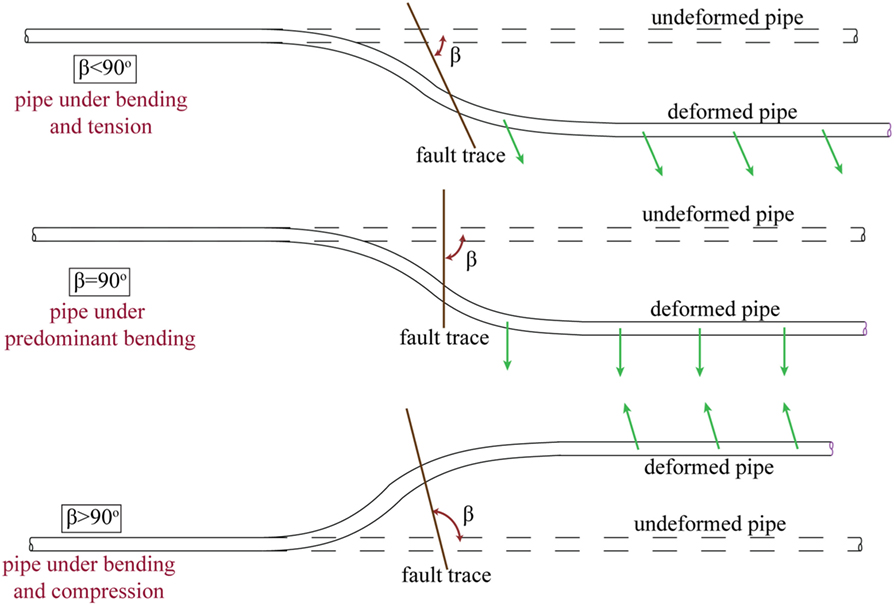
Figure 3. Schematic illustration in plan-view of the buried pipe deformation due to faulting with respect to the pipe-fault crossing angle β.
The potentially severe consequences of faulting on buried steel fuel pipelines in terms of high developing strains have forced engineers to implement preventive measures at pipe-fault crossings. These measures usually aim either at reducing the pipe–soil friction (e.g., trench backfilling with loose granular soil) or at increasing the pipe strength (e.g., steel grade upgrade). The objective of this paper is to present an overview of such mitigating measures that have been either applied in practice or proposed by researchers. The effectiveness of these measures is then investigated using advanced numerical analysis, and useful remarks are extracted regarding their contribution to pipe protection. For that purpose, a typical buried steel pipeline is considered crossing a strike-slip fault, chosen as a common fault type causing symmetric pipe behavior around the fault trace.
Mitigating Measures
Pipeline protection against the consequences of faulting necessitates the employment of pertinent measures. It is, as a general rule, advisable to avoid pipeline-fault crossings at the stage of pipeline route selection; however, this is often impossible in seismic regions. In case such crossings are unavoidable, it is recommended to avoid sharp bends that increase constraints to axial displacements and may impose additional forces on the pipeline (CEN, 2006; Gantes and Bouckovalas, 2013). In case there are such restrictions in the route selection procedure that bends are necessary close to the fault crossing, then the anchor length has to be considered regarding the location of bends. Nevertheless, and in addition to the above guidelines, further specific measures are often necessary to minimize the potential of pipeline failure. To provide a comprehensive overview, the measures are categorized depending on the way protection is provided: pipe–soil friction reduction (Friction Reduction Measures), pipe strengthening (Pipe Strengthening Measures), and other measures (Other Measures).
Friction Reduction Measures
Fault activation forces the pipe to move within the trench, and consequently friction is generated on the pipe–soil interface that results in the development of strains in the pipe wall. Several preventive measures have been proposed, aiming at reducing the soil-induced friction. A detailed description of such measures is provided subsequently and then a summary is presented in Table 1, where each “method” is briefly described, differentiating between methods that have been applied in practice or have been only proposed by researchers.
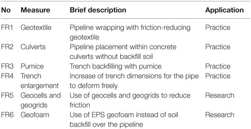
Table 1. Buried pipeline-fault crossing seismic countermeasures for the reduction of soil-induced friction.
• Pipeline wrapping with friction-reducing geotextile (Figure 4A) aims at reducing pipe–soil friction and increasing the anchor length (Gantes and Bouckovalas, 2013). Monroy-Concha (2013) has carried out experimental tests and found that wrapping the pipe with a double layer geotextile is effective only if the distance between the pipe and the trench wall is smaller than half pipe diameter.
• By placing the pipeline within buried prefabricated concrete culverts, which are “sacrificed” during fault rupture, the pipe is retained undeformed (Figure 4B). The lack of backfill within the culvert practically eliminates the pipe–soil friction. The application of this measure is limited to strike-slip fault crossings. Cost and constructional issues (e.g., fabrication, transportation and installation of culverts, and trench widening) have to be considered. Moreover, pipe placement within culverts, especially for high fault offset magnitude, arises constructional issues that engineers have to bear in mind, such as the required size of culverts, construction and transportation of oversized culverts, extensive excavation for culvert installation, as well as the capability of culverts behaving as they are expected.
• Trench backfilling with loose granular soil, mainly pumice, aims at reducing soil resistance and consequently soil-induced friction on the pipe (Gantes and Bouckovalas, 2013).
• Construction of a wider trench can contribute toward allowing pipeline deformation to take place over a longer length and therefore avoiding strain concentration (Figure 4C). To evaluate the efficiency of this design approach, it is necessary to consider trench dimensions. The latter cannot be realized in common design procedures, where the beam-type FEM model is implemented. Thus, either research results are necessary for the quantification of the effect of trench widening on soil spring properties (Chaloulos et al., 2015) or using the continuum FEM model is necessary [e.g., Trifonov (2015)].
• Geocells and geogrids can be used in the trench above the pipeline (Hegde and Sitharam, 2015), or the pipe trench can be backfilled with tire-derived aggregate surrounded by sand (Sim et al., 2012) to reduce pipe strains.
• The use of expanded polystyrene (EPS) geofoam as backfill material has also been proposed, taking advantage of EPS’ very low weight. EPS has been applied in transportation infrastructure for the protection of culverts and buried pipes against the applied horizontal and vertical forces. Bartlett et al. (2015) have presented experimental and numerical studies, indicating that EPS geofoam backfill can be effective for the protection of buried steel pipes against permanent ground displacements.
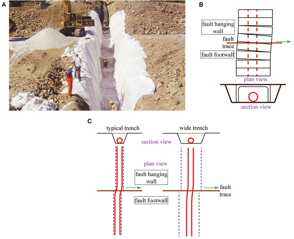
Figure 4. Pipe-fault crossing measures for the reduction of soil-induced friction: (A) pipeline wrapping with friction-reducing geotextile (Gantes and Bouckovalas, 2013), (B) pipe placement within concrete culverts, and (C) trench enlargement.
Pipe Strengthening Measures
There is a second category of measures, aiming at increasing the pipe strength. This task can be achieved by upgrading the steel grade, increasing the pipe wall thickness to reduce the pipe’s bending deformation by increasing pipe stiffness (Gantes and Bouckovalas, 2013; Karamanos et al., 2014), or by wrapping the pipeline with composite wraps (Mokhtari and Alavi Nia, 2015; Trifonov and Cherniy, 2016). These measures are briefly listed in Table 2.
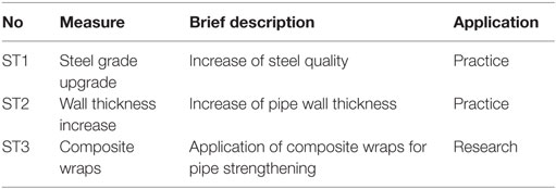
Table 2. Buried pipeline-fault crossing seismic countermeasures for pipe strengthening.
Other Measures
Seismic countermeasures that cannot be classified either as friction-reducing (Friction Reduction Measures) or pipe strengthening (Pipe Strengthening Measures) are included in this third category. These measures are presented subsequently in detail and are summarized in Table 3.
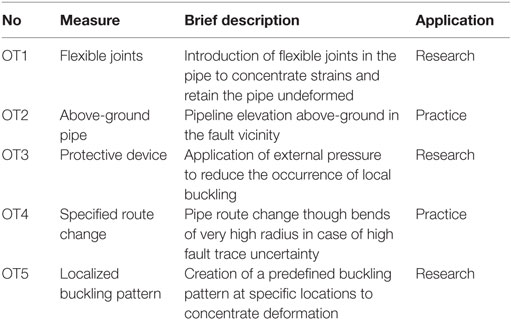
Table 3. Buried pipeline-fault crossing other seismic countermeasures.
• By introducing bellow-type flexible joints between adjacent pipe parts in the fault vicinity, deformations due to fault activation are absorbed as rotations at the joints, and the pipe steel segments remain barely undeformed and consequently unstressed (Melissianos et al., 2016). The behavior of flexible joints in pipes under fault rupture is depicted in Figure 5, indicating that the continuous pipe structural system is modified to “segmented.” Flexible joints of bellow-type have not been used until now in buried high pressure pipes subjected to faulting applications. However, the extensive parametric feasibility study presented in Melissianos et al. (2016) provides encouraging results on the efficiency of this approach. It is noted that the practical application of joints has to be preceded by practical and regulatory provisions regarding several technological issues, such as the pipe-joint welding and the joint protection against corrosion and external damage.
• By elevating sufficiently long part of the pipeline on the two sides of fault crossing above the ground, on appropriate supports, the pipe is no longer forced to follow ground movement during fault activation. The efficiency of this approach has been clearly demonstrated in case of the Trans-Alaska pipeline—Denali fault crossing (Honegger and Nyman, 2004). The solution is applicable in strike-slip fault crossings, and it is the recommended option in case the expected fault offset is significantly high. It has to be noted that a different design procedure (design in operable conditions and against accidental actions) has to be followed for the above-ground segment of the pipeline.
• Zhang et al. (2016) have proposed to use a protective device, whose function relies on imposing external hydrostatic pressure on the pipeline in order to avoid local buckling.
• By constructing a dog–leg structure, involving a pipe route change with bend of very high radius, the pipeline deformation is allowed to take place within a larger area, especially in case there is great uncertainty on the fault trace location (Besstrashnov and Strom, 2011). The application of this solution may be impeded by environmental considerations, given that a larger area has to be affected due to the route modification. Additionally, increased cost is required due to the need for more extensive excavation.
• It has been proposed to create a predefined buckling pattern, consisting of localized deformation of the pipe wall in shape of local buckling at specified sections, in order to control the location and mode of pipe local deformation and increase the fault displacement that can be absorbed (Hasegawa et al., 2014).
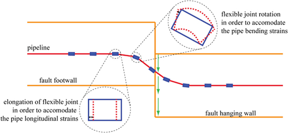
Figure 5. Schematic illustration of flexible joints’ behavior in pipes under fault rupture.
Case Study
Reference Pipeline
A typical API5L-X65 high pressure and large diameter natural gas pipeline is considered as the reference pipe (abbreviated as R hereinafter), featuring diameter of D = 914 mm and wall thickness of t = 12.7 mm. The pipe steel properties are elastic modulus E = 210 GPa, yield stress fy = 448.5 MPa, yield strain εy = 0.214%, failure stress fu = 510 MPa, and failure strain εu = 18%. The pipeline is assumed to be corrosion- and defect-free, coated with coal tar, and buried under 1.30 m of loose cohesionless sand with unit weight γ = 18 kN/m3 and internal friction angle φ = 36°. The interface angle of pipe–soil friction δ is estimated as:
where f is the coating-dependent factor that relates the internal friction angle φ of the soil to the friction angle at the pipe–soil interface, considered here as f = 0.90. Keeping in mind that one of the main goals of mitigating measures is the reduction of the soil-induced friction on the pipe, the corresponding maximum axial (Tu) soil friction force is estimated after ALA (American Lifelines Alliance, 2005) as:
where D is the pipe external diameter, α is the adhesion factor [see Appendix B of ALA (American Lifelines Alliance, 2005)], c is the soil cohesion (here taken equal to 0), H is the depth to pipe centerline, and Ko is the coefficient of pressure at rest. Similar relations for the transverse soil springs are also taken from the same code and are not repeated here in the interest of brevity.
The eventual pipe internal pressure counterbalances the external soil pressure and acts beneficially against local buckling occurrence. Thus, considering a worst-case scenario (e.g., unpressurized pipe due to maintenance), the internal pressure is neglected. The pipeline is intercepted by a strike-slip fault with vertical fault plane, while for the pipe-fault crossing angle β (Figure 1) three indicative values are considered, namely β = 75°, β = 90°, and β = 105°. Finally, the code-based strain limits for the pipeline under consideration are obtained from Eqs 1 and 2, equal to 2% for the tensile and 0.39% for the compressive limit.
Fuel pipelines are buried below the ground surface for protection mainly against corrosion and accidental or third-party damage. Burial depth in practice ranges from 1.0 to 3.0 D at fault crossings. These upper layers of the ground are usually earth fill with inhomogeneous properties, which in case of fault activation may deviate the rupture propagation from the underlying bedrock to the ground surface. In such case, which is very common in nature, uncertainty regarding the exact fault trace location on the ground surface emerges. Seismological, geological, and geotechnical surveys are required to estimate the length over which the fault trace might “appear” on the ground surface. This length may range from a few meters to hundreds of meters on each fault wall. Within the presented study, the length of fault trace uncertainty is assumed to be 100 m on each side of the fault trace. It is also noted that in current engineering practice, fault trace uncertainty is encountered by applying the mitigation measure along this entire length. This approach is adopted also hereinafter by assuming that the fault trace is located in the middle of the pipe modeled length, while alternative trace locations are not examined considering that sufficient pipeline length is modeled on both sides of the fault.
Numerical Modeling
Numerical modeling of the pipeline-fault crossing is carried out using the commercial FEM software ADINA (ADINA R&D, 2006). The FE model is based on the suggestions of Eurocode 8—Part 4 (CEN, 2006), ALA (American Lifelines Alliance, 2005). A beam-type numerical model is developed, where the pipe is meshed with PIPE elements, which are two-node beam-type elements including supplementary degrees-of-freedom to account for the additional stresses caused by the cross-section ovalization. The pipeline is meshed into 4,000 pipe elements with length 0.25 m each. Sensitivity analyses have been conducted on the mesh density with respect to accuracy and computational cost efficiency. The modeled pipe length is sufficient in order for attenuation of strains due to fault activation to have fully developed. Hence, boundary conditions at the ends have no effect. Fixity has been applied only on one end for numerical reasons. Furthermore, the numerical model on the use of flexible joints has been validated based on experimental results presented in Melissianos et al. (2017). The pipe strain-state is assessed through stresses and strains that are calculated at integration points of several cross-sections along the pipeline. Strain estimation is essential in order to perform the safety checking, i.e., to check whether the developed strain exceeds the code-based limit for avoiding tensile fracture and/or local buckling. Moreover, sensitivity analyses that were carried out revealed that modeling each meter of pipe with four elements are sufficient to reliably assess the pipe behavior.
The surrounding soil is modeled with non-linear translational springs, whose properties are estimated according to ALA provisions (American Lifelines Alliance, 2005), which connect pipe nodes to “ground nodes.” It has to be noted that backfill soil properties are assumed to be similar to those of the native soil. This assumption is commonly applied in practice and is based on the construction process of buried pipelines, where the trench is usually backfilled with the soil that was excavated during trenching. An overview of the numerical model is schematically shown in Figure 6. Axial springs model the pipe–soil friction (yield force 41 kN/m and yield displacement 5 mm), transverse horizontal (lateral) springs model the soil resistance to pipe lateral movement in the trench (yield force 320 kN/m and yield displacement 23 mm), while vertical springs in the upward (yield force 45 kN/m and yield displacement 4.6 mm) and downward direction (yield force 1,494 kN/m and yield displacement 114 mm) model the soil resistance to any vertical pipe movement. The fault plane divides the earth crust into two blocks: (i) the moving one is called hanging wall and is modeled by applying the fault movement as imposed displacement on “ground nodes” and (ii) the stable one is called footwall, in which fixities are applied on “ground nodes.”
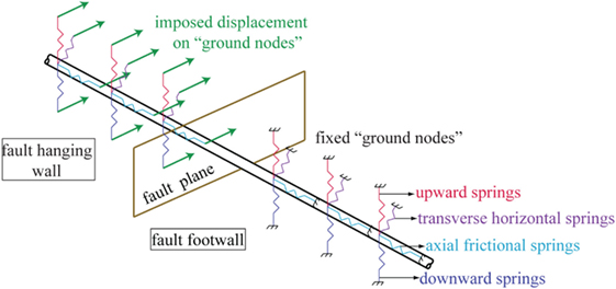
Figure 6. Numerical modeling of pipeline-fault crossing.
Analyses are performed by considering geometrical and material non-linearity and employing either Newton–Raphson or arc-length (Bathe and Dvorkin, 1983) solution algorithms. The number of analysis steps is selected in such a way that numerical convergence is achieved, and at the same time the displacement is applied smoothly in order to be consistent with the quasi-static nature of the problem. Non-seismic and operational loads (e.g., internal pressure, hydraulic actions, etc.) are not taken into account.
Preventive Measures
The case study aims at evaluating the effectiveness of alternative mitigating measures against the consequences of faulting on buried steel pipelines. To that effect, the commonly adopted measures in design are examined, namely pipe wrapping with geotextiles, pipe placement within culverts, pumice backfilling, steel grade upgrade, and wall thickness increase. These measures have been implemented in several pipeline-fault crossings (Besstrashnov and Strom, 2011; Gantes and Bouckovalas, 2013; Chenna et al., 2014). Additionally, numerical results presented in Melissianos et al. (2015, 2016) indicate that the integration of flexible joints is a promising solution for the protection of buried pipes, considering on the one hand that joints are commercial products and on the other hand the absence of significant constructional requirements. Thus, the introduction of joints will also be examined and compared to the above commonly used measures. The examined measures are the following, considering that each is applied along the entire fault trace uncertainty length:
• Pipe Wrapping with Friction-Reducing Geotextile (FR1)
The pipeline is wrapped with friction-reducing geotextile in order to reduce the developing friction on the pipe–soil interface (Table 4). The interface angle δ′ of pipe–soil friction is taken equal to half of the one in case of the reference pipeline (R), i.e., δ′ = 0.5 δ, which is an assumption often adopted in design practice. Thus, the axial spring force is reduced accordingly (Figure 7). Numerical implementation of pipe wrapping with friction-reducing geotextile is carried out by modifying the properties of the axial springs only.
• Use of Culverts (FR2)
The pipeline segment along the 200-m uncertainty length is placed within concrete culverts without backfill soil (Table 4). The lack of backfilling is numerically modeled by removing the soil springs along this particular length. The friction between the pipe bottom and the trench base is neglected as the contact surface is very small.
• Pumice Backfill (FR3)
The trench is backfilled with pumice (Table 4) having unit weight γ = 8 kN/m3, cohesion c = 0 kPa, and internal friction angle φ = 33°. The soil properties after ALA (American Lifelines Alliance, 2005) are presented in Figure 7. Numerical modeling of the pumice backfill as preventive measure is carried out by recalculating the axial, transverse horizontal (lateral), and upward soil spring properties along the fault trace uncertainty length. Downward soil springs are estimated using the properties of the native soil and are therefore not modified. Additionally, it is assumed that the trench is wide enough so that its boundaries are not to significantly modify the lateral spring properties. Even though this assumption might be considered as a drawback in lateral spring calculation, the effect of trench boundaries is identified in Appendix B of ALA guidelines (American Lifelines Alliance, 2005) but is not quantified. To address this task, there are very recent research efforts that try to quantify the effect of trench dimensions (Chaloulos et al., 2015, 2017).
• Steel Grade Upgrade (ST1)
The steel grade is upgraded to API5L-X80 with properties: elastic modulus E = 210 GPa, yield stress fy = 530 MPa, yield strain εy = 0.25%, failure stress fu = 621 MPa, and failure strain εu = 18% (Table 4). Numerical modeling of steel grade upgrade (ST1) is carried out by modifying the steel properties of the reference pipelines (R), while soil spring properties are not modified (Figure 7).
• Wall Thickness Increase (ST2)
The pipe wall thickness is increased from 12.70 to 19.05 mm, which is a commercially available thickness for pipes with diameter equal to 914 mm (Table 4). Numerical modeling of wall thickness increase (ST2) is performed through the increase of the thickness of the pipe cross-section of the reference pipeline (R), while soil spring properties are not modified (Figure 7).
• Flexible Joints (OT1)
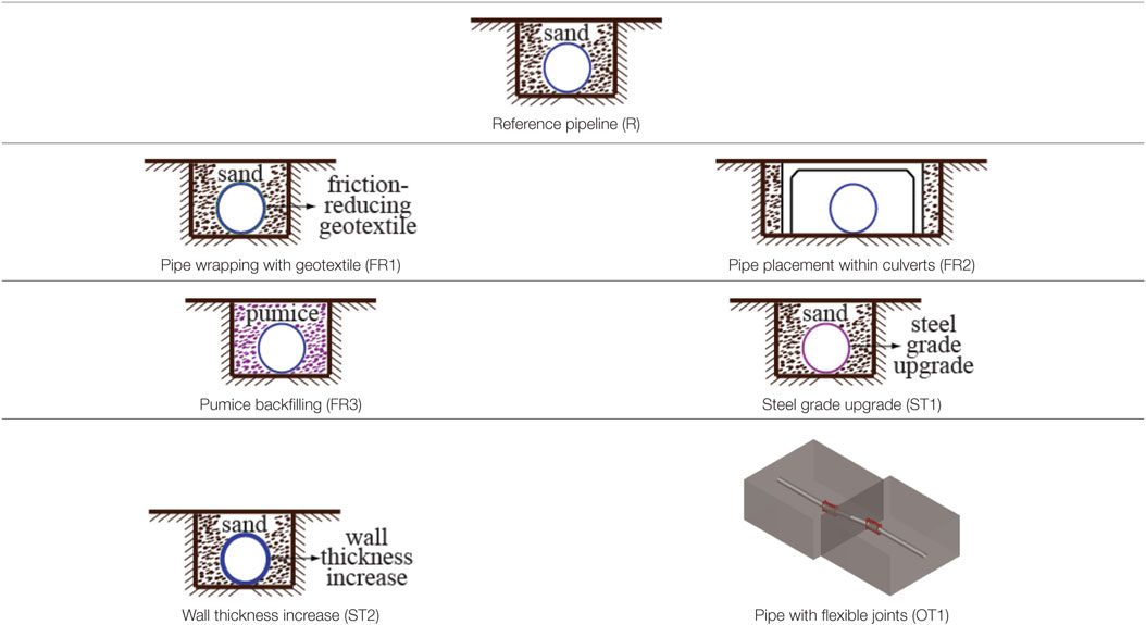
Table 4. Mitigating measures under investigation.
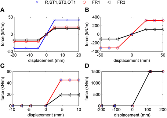
Figure 7. Soil spring properties: (A) axial, (B) transverse horizontal, (C) vertical upward, and (D) vertical downward.
Hinged bellow-type flexible joints are placed along the pipeline around the fault vicinity, adopting the configuration proposed in Melissianos et al. (2016) and taking also into account the fault trace uncertainty. Hinged bellows are numerically modeled as generic flexible joints (EJMA, 2008; Peng and Peng, 2009) represented by a rotational spring at the center point without modeling the joint length. The relative axial and lateral displacement capabilities are restricted through appropriate numerical constraints. The adopted modeling approach for pipelines with hinged flexible joints under fault has been verified in Melissianos et al. (2017).
A summary of the reference pipe and the measures under investigation is presented in Table 4 in order to provide a comprehensive overview of the case study.
Moreover, the soil spring properties for each examined case are illustrated in Figure 7.
Presentation and Discussion of Results
The maximum tensile and compressive strains obtained from the numerical analyses with respect to the normalized fault offset (Δ/D) for crossing angle β = 75° are shown in Figure 8, where additionally the horizontal lines indicate the ALA (American Lifelines Alliance, 2005) strain limits. It is observed that the maximum developing tensile strains εt,max increase with fault offset increase, while the corresponding compressive strains εc,max increase only up to fault offset equal roughly to Δ/D = 1, which is attributed to the fact that for low fault offset the pipe behavior is mainly bending. Then, as the fault offset increases further, the pipe is subjected mainly to tension and consequently compressive strains due to bending are offset.
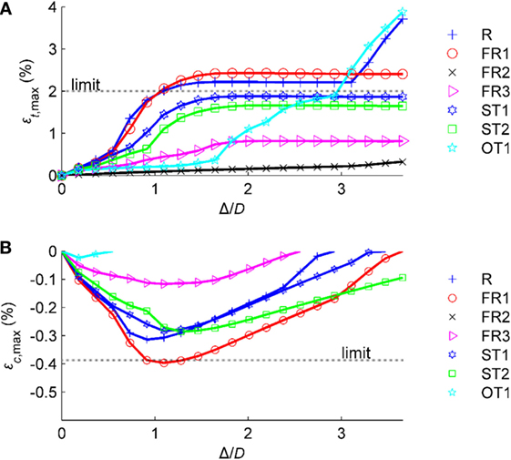
Figure 8. Maximum (A) tensile (εt,max) and (B) compressive (εc,max) strains with respect to normalized fault offset (Δ/D) for crossing angle β = 75°.
Regarding the efficiency of the examined alternative mitigating measures, it is primarily noted that the efficiency of pipe strengthening measures, namely steel grade upgrade (ST1) and wall thickness increase (ST2), is very limited in terms of strain reduction. Pipe wrapping with geotextile (FR1) does not protect the pipe neither against tensile fracture nor against local buckling. Even though the motivation for wrapping the pipeline with geotextile is to reduce the developing friction on the pipe surface, in practice this measure proves insufficient, taking into account that the pipe surface (including the coating) is already relatively smooth and thus the reduction of friction is limited, while transverse soil–pipe interaction remains unaffected. Trench backfilling with pumice (FR3) contributes to strain reduction and may be considered as a moderately effective approach. The most effective measures are the use of culverts (FR2) and the integration of flexible joints (OT1). Comparing these two approaches, it is shown that for this crossing angle: (i) flexible joints are effective only for low fault offset regarding tensile strains because as the fault offset increases the hinged layout of the joint cannot relief the axial strains due to overall tension, (ii) flexible joints are significantly effective in protection against local buckling as for low fault offset already compressive strains are practically eliminated, and (iii) culverts provide the maximum tensile strain reduction and at the same time do not “allow” the development of compression.
In case the pipe crosses the fault plane perpendicularly (β = 90°), it is predominately subjected to bending. The maximum tensile and compressive strains with respect to the normalized fault offset (Δ/D) are depicted in Figure 9 for all mitigating measures. It is observed again that steel grade upgrade (ST1), wall thickness increase (ST2), and pipe wrapping with geotextile (FR1) are not effective. In particular, the compressive strains exceed the code-based strain limit for very low offset. Moreover, use of culverts (FR2), trench backfilling with pumice (FR3), and the integration of flexible joints (OT1) can affectively protect the pipe by minimizing the potential of tensile failure and/or local buckling through the limitation of the pipe developing strains.
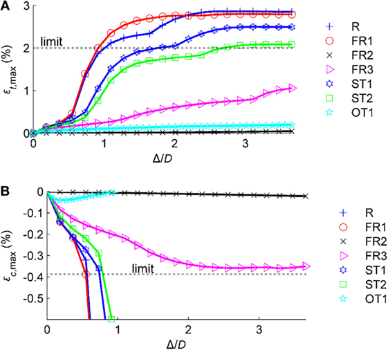
Figure 9. Maximum (A) tensile (εt,max) and (B) compressive (εc,max) strains with respect to normalized fault offset (Δ/D) for crossing angle β = 90°.
The design of a pipe-fault crossing with angle β > 90° is not recommended by pertinent structural codes [e.g., Eurocode 8—Part 4 (CEN, 2006), ALA (American Lifelines Alliance, 2005)] and is avoided as much as possible in design in order to prevent the pipeline from being subjected to significant compression. The resulting tensile and compressive strains with respect to the fault offset (Δ/D) are illustrated in Figure 10. It is again observed that steel grade upgrade (ST1), wall thickness increase (ST2), and pipe wrapping with geotextile (FR1) are insufficient solutions. Pumice backfill (FR3) can be seen as a viable solution only for low fault offset magnitudes. On the other hand, pipe placement within culverts (FR2) and integration of flexible joints (OT1) remain the most efficient solutions in terms of reducing the developing pipe strains.
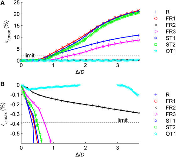
Figure 10. Maximum (A) tensile (εt,max) and (B) compressive (εc,max) strains with respect to normalized fault offset (Δ/D) for crossing angle β = 105°.
It is noted that the case of pipe with flexible joints (OT1) differs from the other cases in terms of developing strains, and therefore compressive strains for this case (Figure 10B) vary with respect to fault offset, and the pertinent strain curve is not strictly increasing. Flexible joints act as “internal hinges” and thus the adjacent pipe parts are relatively “rotated.” For low fault offset the rotation of joints is small, and compression is developed. Then, compression is progressively minimized as joints are rotated until strains are practically eliminated. Compression is again developed for higher fault offset, due to the significant pipe deformation in the trench. However, it is of great importance to point out that in FR2 case the pipe will undergo significant lateral deformation for large fault offset magnitude that can be judged as a state of global instability. This fact is indicatively illustrated in Figure 11 for fault offset Δ/D = 4, where the pipeline transverse horizontal displacement is presented on the vertical axis and the distance from the fault trace on the horizontal axis. It is shown that the pipe lateral displacement is significant, triggering the question whether this displacement can take place within the culverts. Similarly, in case of integrating joints (OT1), large relative rotations are encountered at the joints, which may exceed the joint rotational capacity and/or exhaust the available trench width. The pipe deformation of OT1 case is also presented in Figure 11. This is at the expense of large relative rotations at the flexible joints, which must not exceed the joints’ rotational capacity.
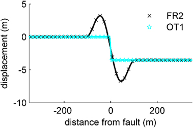
Figure 11. Horizontal displacement of pipeline placed within culverts (FR2) and of pipeline with flexible joints (OT1) for fault offset Δ/D = 4 and crossing angle β = 105°.
As a final comment on the use of geotextile, it is derived from Figures 8–10 that within a specific range of fault displacement for all crossing angles, a relatively minor strain amplification is detected if friction-reducing geotextile is used. This is attributed to the fact that even though friction springs are softer due to the geotextile and consequently developing axial strains are lower, transverse springs remain unaffected, thus bending action dominates the response, and hence bending strains are higher. Therefore, longitudinal strains, which are the summation of axial and bending strains, are slightly higher in some cases.
Summary and Conclusion
The protection of buried steel fuel pipelines subjected to seismic fault rupture has been reviewed and investigated. The mitigating measures commonly used in practice and/or investigated in the literature have been presented, briefly identifying their advantages and disadvantages and discussing constructional considerations of each approach. Most such measures aim either at minimizing the soil-induced friction along the pipeline or at strengthening the pipeline. Even though significant experimental, analytical, and numerical research has been conducted over the past decades and until now, pertinent research on mitigating measures can been seen as limited. Thus, the application of these seismic countermeasures is mostly based on engineering judgment and experience.
Numerical evaluation of the efficiency of alternative mitigating measures, namely pipe wrapping with geotextile, use of culverts, trench backfilling with pumice, steel grade upgrade, pipe wall thickness increase, and integration of flexible joints, has been presented. A beam-type FEM model has been developed, and aspects on the numerical modeling of each measure are highlighted. A typical buried steel pipeline subjected to strike-slip fault rupture is selected as a case study to examine the efficiency of the measures in terms of strain reduction. Three characteristic pipe-fault crossing angles are examined to demonstrate the effect of this critical design parameter on the effectiveness of protection measures. The uncertainty regarding the exact fault trace location has been also considered in the analysis by considering that each measure is applied over a sufficiently long part of the pipeline to cover this uncertainty. The main conclusions of this investigation can be summarized as follows:
• Pipeline wrapping with friction-reducing geotextile is also not an effective mean of protection, as developing strains are similar to those of the unprotected pipe.
• The use of prefabricated concrete culverts can decisively reduce the potential of pipe failure, either tensile fracture or local buckling by significantly reducing pipe strains. This is attributed to the lack of backfill within the culverts, where the pipe is placed. The use of culverts is associated to increased cost, as well as several constructional issues. In case the pipe is subjected to bending and tension (pipe-fault crossing angle β < 90°), pipe developing compression is practically zero. Thus, the effectiveness of culverts in such case is decisive in terms that compression is not developed. In case the pipe is subjected to compression (pipe-fault crossing angle β > 90°), the capability of culverts to follow the fault movement may be questioned, as well as the capability of pipe deformation within the culverts.
• Trench backfilling with light-weighted pumice is a moderately effective way to protect the pipe, provided that the soil material used in the construction field is well-graded and the backfilling process is carried out following good engineering practice. This approach could be selected in case the use of culverts or the integration of flexible joints is not a viable solution.
• Pipe strengthening measures, namely steel grade upgrade and pipe wall thickness increase, cannot provide sufficient strain reduction and their efficiency is limited, regardless the pipe-fault crossing angle. Results show that these design approaches are only meaningful if the expected magnitude of fault rupture is relatively low.
• The integration of hinged bellow-type flexible joints is a very promising alternative for the protection of buried steel pipelines against seismic fault activation for all considered pipe-fault crossing angles, provided that the technological issues mentioned in Section “Other Measures” are addressed in a satisfactory manner. However, decline of crossing angle leads to tensional rather than bending pipe behavior, which reduces the joints’ efficiency. Moreover, the joint rotation capability for high fault offset has to be examined in detail.
Finally, it is noted that the selection of a mitigating measure has to be carried out within a techno-economic framework. Therefore, considering the most effective measures among the examined ones, designers have to take into account, among other issues: (i) the manufacturing and transportation cost of culverts at the construction site and the need for excavation of greater amount of soil, compared to the case of a typical trench, (ii) the availability and cost of well-graded pumice at remote construction sites and the requirement for special backfilling process, and (iii) the production cost of customized flexible joints and the joints’ compliance with the pipe operable conditions. Engineers therefore have to achieve a balance between safety and economy within the specific requirements defined by the pipeline operator and the regulatory authorities.
Author Contributions
CG supervised the theoretical background and organized the research process. VM carried out the numerical analyses and prepared the results.
Conflict of Interest Statement
The authors declare that the research was conducted in the absence of any commercial or financial relationships that could be construed as a potential conflict of interest.
Funding
Part of the present work has been cofinanced by the European Union (European Social Fund—ESF) and Hellenic National Funds through the Operational Program “Education and Lifelong Learning” (NSRF 2007-2013)—Research Funding Program “Aristeia II,” project “ENSSTRAM—Novel Design Concepts for Energy Related Steel Structures using Advanced Materials,” grant number 4916.
References
Abdoun, T. H., Ha, D., O’Rourke, M. J., Symans, M. D., O’Rourke, T. D., Palmer, M. C., et al. (2009). Factors influencing the behavior of buried pipelines subjected to earthquake faulting. Soil Dyn. Earthq. Eng. 29, 415–427. doi: 10.1016/j.soildyn.2008.04.006
ADINA R&D. (2006). Theory and Modeling Guide Volume: I ADINA, Report AED 06-7. Watertown, MA, USA: ADINA R&D, Inc.
American Lifelines Alliance. (2005). Guidelines for the Design of Buried Steel Pipe. American Lifelines Alliance.
Bartlett, S. F., Lingwall, B. N., and Vaslestad, J. (2015). Methods of protecting buried pipelines and culverts in transportation infrastructure using EPS Geofoam. Geotext. Geomembr. 43, 450–461. doi:10.1016/j.geotexmem.2015.04.019
Bathe, K. J., and Dvorkin, E. N. (1983). On the automatic solution of nonlinear finite element equations. Comput. Struct. 17, 871–879. doi:10.1016/0045-7949(83)90101-3
Besstrashnov, V. M., and Strom, A. L. (2011). Active faults crossing trunk pipeline routes: some important steps to avoid disaster. Nat. Hazards Earth Syst. Sci. 11, 1433–1436. doi:10.5194/nhess-11-1433-2011
Canadian Standards Association. (2007). Z662-07 Oil and Gas Pipeline Systems. Mississauga: Canadian Standards Association.
CEN. (2006). Eurocode 8: Design of Structures for Earthquake resistance – Part 4: Silos, Tanks and Pipelines, Vol. 3. Brussels: European Committee for Standard.
Chaloulos, Y. K., Bouckovalas, G. D., and Karamitros, D. K. (2017). Trench effects on lateral P-Y relations for pipelines embedded in stiff soils and rocks. Comput. Geotech. 83, 52–63. doi:10.1016/j.compgeo.2016.10.018
Chaloulos, Y. K., Bouckovalas, G. D., Zervos, S. D., and Zampas, A. L. (2015). Lateral soil–pipeline interaction in sand backfill: effect of trench dimensions. Comput. Geotech. 69, 442–451. doi:10.1016/j.compgeo.2015.05.014
Chaudhary, V., Pasupuleti, V. D. K., and Ramancharla, P. K. (2013). Finite element analysis of buried continuous pipeline subjected to fault motion. Int. J. Struct. Eng. 4, 314–331. doi:10.1504/IJSTRUCTE.2013.056981
Chenna, R., Terala, S., Singh, A. P., Mohan, K., Rastogi, B. K., and Ramancharla, P. K. (2014). Vulnerability assessment of buried pipelines: a case study. Front. Geotech. Eng. 3:24–33.
EJMA. (2008). Standards of the Expansion Joint Manufacturers Association, Inc, 9th Edn. New York, NY, USA: Expansion Joint Manufacturers Association, Inc.
Gantes, C. J., and Bouckovalas, G. D. (2013). Seismic verification of the high pressure natural gas pipeline Komotini–Alexandroupoulis–Kipi in areas of active fault crossings. Struct. Eng. Int. 23, 204–208. doi:10.2749/101686613X13439149157164
Ha, D., Abdoun, T. H., O’Rourke, M. J., Symans, M. D., O’Rourke, T. D., Palmer, M. C., et al. (2010). Earthquake faulting effects on buried pipelines – Case history and centrifuge study. J. Earthq. Eng. 14, 646–669. doi:10.1080/13632460903527955
Hegde, A. M., and Sitharam, T. G. (2015). Experimental and numerical studies on protection of buried pipelines and underground utilities using geocells. Geotext. Geomembr. 43, 372–381. doi:10.1016/j.geotexmem.2015.04.010
Honegger, D. G., Nyman, D. J., Johnson, E. R., Cluff, L. S., and Sorensen, S. P. (2004). Trans-Alaska pipeline system performance in the 2002 Denali Fault, Alaska, Earthquake. Earth. Spectra 20, 707–738. doi:10.1193/1.1779239
Indian Institute of Technology Kanpur, Gujarat State Disaster Management Authority. (2007). Guidelines for Seismic Design of Buried Pipelines. Kanpur, India: National Information Center of Earthquake Engineering.
Joshi, S., Prashant, A., Deb, A., and Jain, S. K. (2011). Analysis of buried pipelines subjected to reverse fault motion. Soil Dyn. Earthq. Eng. 31, 930–940. doi:10.1016/j.soildyn.2011.02.003
Karamanos, S. A., Keil, B., and Card, R. J. (2014). “Seismic design of buried steel water pipelines,” in Proceedings of the Pipelines 2014: from Underground to the Forefront of Innovation and Sustainability, (Portland, OR, USA: ASCE), 1005–1019.
Karamitros, D. K., Bouckovalas, G. D., Kouretzis, G. P., and Gkesouli, V. (2011). An analytical method for strength verification of buried steel pipelines at normal fault crossings. Soil Dyn. Earthq. Eng. 31, 1452–1464. doi:10.1016/j.soildyn.2011.05.012
Karamitros, D. K., Bouckovalas, G. D., and Kouretzis, G. P. (2007). Stress analysis of buried steel pipelines at strike-slip fault crossings. Soil Dyn. Earthq. Eng. 27, 200–211. doi:10.1016/j.soildyn.2006.08.001
Kennedy, R. P., Chow, A. W., and Williamson, R. A. (1977). Fault movement effects of buried oil pipeline. ASCE J. Transp. Eng. 103, 617–633.
Kennedy, R. P., and Kincaid, R. H. (1983). “Fault crossing design for buried gas oil pipeline,” in Proceedings of the ASME 1983 Pressure Vessels and Piping Division Conference (Portland, OR: ASME).
Kokavessis, N. K., and Anagnostidis, G. S. (2006). “Finite element modeling of buried pipelines subjected to seismic loads: soil structure interaction using contact elements,” in Proceedings of the ASME 2006 Pressure Vessels and Piping Division Conference, (Vancouver, Canada: ASME).
Liu, B., Liu, X., and Zhang, H. (2009). Strain-based design criteria of pipelines. J. Loss Prev. Process Ind. 22, 884–888. doi:10.1016/j.jlp.2009.07.010
Liu, X., Zhang, H., Han, Y., Xia, M., and Zheng, W. (2016). A semi-empirical model for peak strain prediction of buried X80 steel pipelines under compression and bending at strike-slip fault crossings. J. Nat. Gas Sci. Eng. 32, 465–475. doi:10.1016/j.jngse.2016.04.054
Melissianos, V. E., Vamvatsikos, D., and Gantes, C. J. (2015). “Probabilistic assessment of innovative mitigating measures for buried steel pipeline – fault crossing,” in Proceedings of the ASME 2015 Pressure Vessels & Piping Conference PVP2015 (Boston, MA, USA: ASME).
Melissianos, V. E., Korakitis, G. P., Gantes, C. J., and Bouckovalas, G. D. (2016). Numerical evaluation of the effectiveness of flexible joints in buried pipelines subjected to strike-slip fault rupture. Soil Dyn. Earthq. Eng. 90, 395–410. doi:10.1016/j.soildyn.2016.09.012
Melissianos, V. E., Lignos, X. A., Bachas, K. K., and Gantes, C. J. (2017). Experimental investigation of pipes with flexible joints under fault rupture. J. Constr. Steel Res. 128, 633–648. doi:10.1016/j.jcsr.2016.09.026
Mokhtari, M., and Alavi Nia, A. (2015). The influence of using CFRP wraps on performance of buried steel pipelines under permanent ground deformations. Soil Dyn. Earthq. Eng. 73, 29–41. doi:10.1016/j.soildyn.2015.02.014
Monroy-Concha, M. (2013). Soil Restraints on Steel Buried Pipelines Crossing Active Seismic Faults. Vancouver, BC: The University of British Columbia.
Newmark, N. M., and Hall, W. J. (1975). “Pipeline design to resist large fault displacement,” in Proceedings of the US National Conference on Earthquake Engineering (Ann Arbor, MS), 416–425.
Hasegawa, N., Nagamine, H., and Imai, T. (2014). Development of “steel pipe for crossing fault (SPF)” using buckling pattern for water pipelines. JFE GIHO 31, 61–65.
Odina, L., and Tan, R. (2009). “Seismic fault displacement of buried pipeline using continuum finite element methods,” in Proceedings of the ASME 28th International Conference on Ocean, Offshore and Arctic Engineering, (Honolulu, HW, USA: ASME).
Ogawa, Y., Yanou, Y., Kawakami, M., and Kurakake, T. (2004). “Numerical study for rupture behavior of buried gas pipeline subjected to seismic fault displacement,” in Proceedings of the 13th World Conference on Earthquake Engineering (Vancouver, Canada).
O’Rourke, M. J., and Liu, X. (2012). Seismic Design of Buried and Offshore Pipelines. Buffalo, NY, USA: Multidisciplinary Center for Earthquake Engineering Research.
Sim, W. W., Towhata, I., Yamada, S., and Moinet, G. J. M. (2012). Shaking table tests modelling small diameter pipes crossing a vertical fault. Soil Dyn. Earthq. Eng. 35, 59–71. doi:10.1016/j.soildyn.2011.11.005
Takada, S., Hassani, N., and Fakuda, K. (2001). A new proposal for simplified design of buried steel pipes crossing active faults. Earthq. Eng. Struct. Dyn. 30, 1243–1257. doi:10.1002/eqe.62
Trifonov, O. V. (2015). Numerical stress-strain analysis of buried steel pipelines crossing active strike-slip faults with an emphasis on fault modeling aspects. ASCE J. Pipeline Syst. Eng. Pract. 6, 1–10. doi:10.1061/(ASCE)PS.1949-1204.0000177
Trifonov, O. V., and Cherniy, V. P. (2010). A semi-analytical approach to a nonlinear stress-strain analysis of buried steel pipelines crossing active faults. Soil Dyn. Earthq. Eng. 30, 1298–1308. doi:10.1016/j.soildyn.2010.06.002
Trifonov, O. V., and Cherniy, V. P. (2012). Elastoplastic stress-strain analysis of buried steel pipelines subjected to fault displacements with account for service loads. Soil Dyn. Earthq. Eng. 33, 54–62. doi:10.1016/j.soildyn.2011.10.001
Trifonov, O. V., and Cherniy, V. P. (2016). Application of composite wraps for strengthening of buried steel pipelines crossing active faults. ASME J. Press. Vessel Technol. 138, 060902. doi:10.1115/1.4032915
Uckan, E., Akbas, B., Shen, J., Rou, W., Paolacci, F., and O’Rourke, M. (2015). A simplified analysis model for determining the seismic response of buried steel pipes at strike-slip fault crossings. Soil Dyn. Earthq. Eng. 75, 55–65. doi:10.1016/j.soildyn.2015.03.001
Vazouras, P., Dakoulas, P., and Karamanos, S. A. (2015). Pipe–soil interaction and pipeline performance under strike–slip fault movements. Soil Dyn. Earthq. Eng. 72, 48–65. doi:10.1016/j.soildyn.2015.01.014
Vazouras, P., Karamanos, S. A., and Panos, D. (2010). Finite element analysis of buried steel pipelines under strike-slip fault displacements. Soil Dyn. Earthq. Eng. 30, 1361–1376. doi:10.1016/j.soildyn.2010.06.011
Vazouras, P., Karamanos, S. A., and Dakoulas, P. (2012). Mechanical behavior of buried steel pipes crossing active strike-slip faults. Soil Dyn. Earthq. Eng. 41, 164–180. doi:10.1016/j.soildyn.2012.05.012
Wang, L. R. L., and Wang, L. J. (1995). “Parametric study of buried pipelines due to large fault movement,” in Proceedings of Fourth U.S. Conference on Lifeline Earthquake Engineering (San Francisco, CA), 152–159.
Wang, L. R. L., and Yeh, Y. A. (1985). A refined seismic analysis and design of buried pipelines subjected to vertical fault movement. Earthq. Eng. Struct. Dyn. 13, 75–96. doi:10.1002/eqe.4290130109
Zhang, J., Liang, Z., and Han, C. J. (2014). Buckling behavior analysis of buried gas pipeline under strike-slip fault displacement. J. Nat. Gas Sci. Eng. 21, 921–928. doi:10.1016/j.jngse.2014.10.028
Zhang, J., Liang, Z., Zhang, H., Feng, D., and Xia, C. (2016). Failure analysis of directional crossing pipeline and design of a protective device. Eng. Fail. Anal. 66, 187–201. doi:10.1016/j.engfailanal.2016.04.019
Zhang, L., Zhao, X., Yan, X., and Yang, X. (2016a). A new finite element model of buried steel pipelines crossing strike-slip faults considering equivalent boundary springs. Eng. Struct. 123, 30–44. doi:10.1016/j.engstruct.2016.05.042
Keywords: buried pipeline, fault rupture, protection measure, numerical analysis, design guidelines
Citation: Gantes CJ and Melissianos VE (2016) Evaluation of Seismic Protection Methods for Buried Fuel Pipelines Subjected to Fault Rupture. Front. Built Environ. 2:34. doi: 10.3389/fbuil.2016.00034
Received: 01 November 2016; Accepted: 09 December 2016;
Published: 26 December 2016
Edited by:
Konstantinos Daniel Tsavdaridis, University of Leeds, UKReviewed by:
Hossein Mostafaei, FM Global, USAVasile-Mircea Venghiac, Gheorghe Asachi Technical University of Iaşi, Romania
Oleg V. Trifonov, Gazprom VNIIGAZ, Russia
Copyright: © 2016 Gantes and Melissianos. This is an open-access article distributed under the terms of the Creative Commons Attribution License (CC BY). The use, distribution or reproduction in other forums is permitted, provided the original author(s) or licensor are credited and that the original publication in this journal is cited, in accordance with accepted academic practice. No use, distribution or reproduction is permitted which does not comply with these terms.
*Correspondence: Charis J. Gantes, Y2hnYW50ZXNAY2VudHJhbC5udHVhLmdy