 Arturo Tena-Colunga*
 Héctor Hernández-Ramírez
- Departmento de Materiales, Universidad Autónoma Metropolitana Azcapotzalco, Mexico City, Mexico
In this paper, the authors summarize the results of a parametric study devoted to evaluate the seismic behavior of low to medium rise regular special moment-resisting steel frames with hysteretic energy dissipation devices mounted on chevron steel bracing. For that purpose, 270 different building models were designed considering typical story heights and bay widths used in Mexican practice. The parameters under study were (1) number of stories: 5, 10, 15, 20, and 25, (2) elastic stiffness ratios (α) between the moment frame system and the whole structure (frame-bracing-hysteretic device system): α = 0.25, 0.50, and 0.75, (3) different elastic stiffness balances (β) between the hysteretic device and the supporting braces: β = 0.25, 0.50, and 0.75, (4) post- to pre-yielding stiffness ratios (K2/KELD) for the hysteretic devices of 0.0 (elastic-perfectly plastic), 0.03, and 0.05, and (5) two angles of inclination of the chevron braces with respect to the horizontal axis (θ): 40° and 45°. From the results obtained in this study, optimal stiffness balances α and β are defined to obtain a suitable mechanism where the hysteretic devices yield first and develop their maximum local displacement ductility μ, whereas incipient yielding is only formed at beam ends of the moment frame. Observations are done with respect to: (a) the global ductility capacity for the structure and its relationships with the local displacement ductility capacity for the hysteretic devices for a given combination of α, β, K2/KELD, and θ and (b) overstrength factors (Ω) for design purposes.
Introduction
Although the Mexican engineering community has been interested for more than three decades in hysteretic passive energy dissipation devices (HEDDs), today applications are fewer than 30 including RC and steel buildings (Tena-Colunga, 2007). Applications in other countries worldwide are not much higher, taking aside leading countries in applications, such as Japan. The relatively small number of applications is directly related to the absence of global design parameters and detailed guidelines in official building codes of Mexico and other countries. The absence of such recommendations are due to the lack of enough studies available in the literature (Mexican and worldwide) focused on defining global design parameters that could be easily inserted in a traditional seismic building code format such as those found in Mexican Codes (for example, Tena-Colunga et al., 2009) or US recommendations (for example, ASCE 7, 2010).
Most previous studies oriented to define global seismic design parameters considered single degree of freedom systems (SDOFs) (for example, Wu and Hanson, 1987) or SDOFs tuned with simple multi-degree of freedom systems (for example, Ciampi et al., 1995; Ramírez et al., 2001; Ruiz and Badillo, 2001; Vargas and Bruneau, 2009). In several studies, equivalent design procedures for structures with HEDD using a supplemental viscous damping approach were validated (for example, Wu and Hanson, 1987; Scholl, 1993; Foti et al., 1998; Ramírez et al., 2001; Benedetti et al., 2014) and/or displacement-based design procedures (for example, Ramírez et al., 2001; Chen et al., 2007; Symans et al., 2008).
There are only few studies available where global design parameters suitable to be implemented in building codes have been assessed (Vargas and Bruneau, 2009; Tena-Colunga and Nangullasmú-Hernández, 2015). In order to ensure an elastic behavior for the frame, Vargas and Bruneau (2009) associated the design base shear with: (a) the elastic stiffness ratio (α) between the bracing-HEDD and the steel moment frame and (b) the peak ductility capacity (μd) for the hysteretic energy dissipation device. Vargas and Bruneau (2009) also assessed the overstrength factor (Ω) related to the yielding of the HEDDs while the frame remains elastic. Tena-Colunga and Nangullasmú-Hernández (2015) conducted a parametric study devoted to the evaluation, using pushover analyses, of the seismic behavior of low to medium rise regular reinforced concrete intermediate moment-resisting frames (RC-IMRFs) with hysteretic energy dissipation devices (HEDDs) mounted on chevron steel bracing. The main purpose of the described study was to assess global seismic design parameters that could be easily inserted in the seismic design philosophy of Mexican codes. Different elastic stiffness ratios between the moment frame system and the whole structure (α) and between the hysteretic device and the supporting braces (β) were considered, among other relevant structural parameters, as described in following sections.
The research reported in this paper is directly related to the one reported by Tena-Colunga and Nangullasmú-Hernández, as it is a parallel study for a different structural system and material: special moment-resisting steel frames (SMRSFs). The purpose of the study was to assess and validate the range for global design parameters and stiffness balances under study for SMRSFs, which do not necessarily have to coincide with those for a RC-IMRFs. However, the global code-oriented design strategy is general, and therefore, the design strategy and methods coincide with those reported in Tena-Colunga and Nangullasmú-Hernández (2015).
SMRSFs with HEDDs Under Study
Hysteretic energy dissipation devices are considered mounted into SMRSFs using chevron bracing. The following design hypothesis were done: (a) SMRSFs were designed to carry gravitational loads plus their share of seismic lateral loads and respond essentially in the elastic range, but designed according to the capacity-design approach for ductile frames of Mexican codes (NTCEM-04, 2004), which are similar to those specified for special moment frames in standards such as AISC 341 (2010), (b) the supporting chevron system should remain essentially elastic under seismic loading also and, (c) HEDDs are designed under seismic loading to behave inelastically up their maximum local displacement ductility capacity μ. Therefore, the structural system under lateral loading is composed by the SMRSFs and the chevron-bracing-HEDDs system. SMRSFs should be able to carry the gravitational loads after a strong earthquake (remaining essentially elastic) and have additional strength and deformation reserve capacity, whereas HEDDs should respond in the inelastic range of response as structural fuses and the supporting chevron bracing should remain essentially elastic.
For the parametric study, buildings from 5 to 25 stories were considered with a typical plan layout depicted in Figure 1. The floor system is composed of steel decks. In order to balance the lateral stiffness and strength of the floor system in the main orthogonal directions, a chessboard distribution of supporting beams and steel sheets was proposed (Figure 1). HEDDs are mounted on chevron bracing in perimeter frames, as shown in Figure 1.
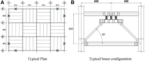
Figure 1. Typical plan layout and brace configuration (dimensions in centimeters). Location of braced bays in plan is depicted with a black cross. (A) Typical plan. (B) Typical brace configuration.
Concurrent bracing at building corners were considered. The reasons behind it are the following: (a) it is commonly used in buildings in Mexico City and worldwide (Figure 2), because architects prefer to use central bays of perimeter frames for the building’s access and, (b) this configuration is the worst-case design scenario for this system from a seismic design perspective, because it favors a high concentration of axial loads in columns, especially due to biaxial dynamic effects. Hence, if the concentration of axial loads in corner columns is limited within reasonable limits while using the proposed design procedure, then, the design strategy should be much more efficient in other bracing configurations.
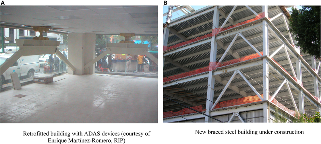
Figure 2. Concentric braced framed buildings in Mexico City with concurrent chevron bracing at building corners. (A) Retrofitted building with ADAS devices (courtesy of Enrique Martínez-Romero, RIP). (B) New braced steel building under construction.
The angle of the chevron bracing with respect to a horizontal plane (θ) was studied because in a previous parametric study (Tena-Colunga, 2002) it was found that the efficiency of HEDD on chevron devices depend on this parameter. Two angles were considered, θ = 40° (story height h = 336 cm) and θ = 45° (h = 400 cm), taking into account typical story heights for regular buildings in Mexico.
Therefore, building models had 5, 10, 15, 20, and 25 stories. Cross sections of beams (W sections), columns (square box sections), and braces (square box sections) were varied along the height (that is, different sections were used for beams, columns, braces, and HEDDs through the height of the studied frames) as schematically depicted with different colors in Figure 3. As a consequence of this design strategy, higher sections were used at the lower levels and relatively smaller sections were used at the top levels due to variation of story shears. It can be noticed also in Figure 3 that, in order to minimize the potential formation of intermediate soft stories (stiffness and/or strength), cross sections of beams and columns are changed at different stories with respect to cross sections of braces. The designed cross sections are reported in detail elsewhere (Hernández, 2015).
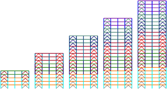
Figure 3. Schematic display of the changes of cross sections for columns, beams, and braces for the frames of the buildings under study.
Parameters Under Study
Four structural parameters (three stiffness-related) were considered with the intention of assessing their extent of application under the general design hypothesis previously mentioned.
The first stiffness parameter is α, defined as the ratio between the global average elastic lateral stiffness for the frame (Kframe, as evaluated as base shear over top-story displacement) with respect to the global average lateral stiffness of the whole frame-bracing-HEDD system (Ktotal):
Three values of α were selected: α = 0.25, where the SMRSFs are more flexible than the bracing-HEDD system, α = 0.50, where the SMRSFs and the bracing-HEDDs system have the same elastic lateral stiffness and, α = 0.75, where the SMRSFs are stiffer than the bracing-HEDD system.
The second stiffness parameter is β, the ratio between the elastic stiffness for the HEDD (KELD, Figure 4) with respect to the elastic lateral stiffness of the supporting chevron braces (Kdiag):
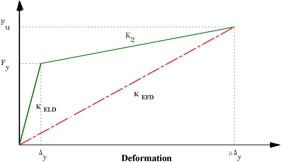
Figure 4. Typical bilinear curve for a hysteretic energy dissipation device.
Three values of β were chosen: β = 0.75, β = 0.50, and β = 0.25. When β < 1.0, the bracing system is stiffer than the HEDD, a desirable requirement for most available HEDDs (for example, ADAS, TADAS, etc.) supported in chevron bracing.
The third stiffness parameter is the post- to pre-yielding stiffness ratios for the HEDD (K2/KELD, Figure 4). Bilinear ratios for elastic-perfectly plastic devices (K2/KELD = 0.0) and hardening devices (K2/KELD = 0.03 and 0.05) were studied. Most structural engineers frequently model HEDD as bilinear, elastic-perfectly plastic. However, it has been observed from most reported experimental research studies that most HEDD develop a secondary stiffness different from 0 (for example, Whittaker et al., 1989; Tsai et. al, 1993). Important differences in peak structural responses may be obtained considering a secondary stiffness different from 0 with respect to an elastic-perfectly plastic idealization for the HEDD for large ductility demands, as suggested in previous parametric studies (Tena-Colunga, 2002; Tena-Colunga and Nangullasmú-Hernández, 2015).
The angle of inclination of the chevron bracing with respect to a horizontal plane (θ) was also assessed for the following reason. In a good design under the structural fuse design concept, the non-linear action should takes place only in the energy dissipator (Figure 4), whereas the bracing system should behave elastically. Therefore, if the “equivalent diagonal” concept is used for the bracing-HEDD system, under a chevron bracing mounting (Figure 2), one can easily demonstrate that the equivalent instantaneous effective stiffness of each brace in the non-linear range (Keqnl) is (Tena-Colunga, 2002):
where Kbrace is the elastic stiffness of the bracing element, KELD is the elastic stiffness of the HEDD (Figure 4), K2 is the postyielding stiffness of the HEDD (Figure 4) and μ is the instantaneous ductility demand of the HEDD (Figure 4). It is clear from the observation of Eq. 3 that the angle of the chevron bracing has an impact on the equivalent instantaneous non-linear effective stiffness and, for a given ductility demand μ for the HEDD, the equivalent non-linear effective stiffness gets smaller as θ is smaller. A smaller effective non-linear stiffness leads to smaller axial forces in the brace-HEDD system and therefore, to smaller axial and shear forces transmitted to beams and columns and hence, leading in theory to smaller demands. That was the purpose of studying θ, to discern if smaller yielding of beams and columns can be obtained for a smaller θ for a given V/W ratio.
In the conducted parametric study that is reported in detail elsewhere (Hernández, 2015), for each height and θ angle, there are 27 different models or combinations of parameters α, β, and K2/KELD (Figure 5). Thus, 135 different models were designed for each θ angle. Then, 270 different models were strictly designed according to code recommendations and analyzed to carry out this parametric study.
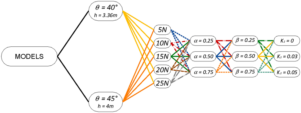
Figure 5. Schematic tree diagram to identify the studied models.
General Code-Oriented Design Procedure
All models were designed under the structural fuse concept using a procedure adapted to a building seismic code format using the initial lateral elastic stiffnesses of the resisting elements. From a code-oriented design perspective, the effective design spectral acceleration, which can also be understood as a V/W ratio, should be obtained using the procedures outlined by the code (this is, from the design spectrum, Figure 6). However, as it is shown later when discussing non-linear dynamic analyses, an effective design base shear V/W = 0.10 is obtained for the design spectrum for the lake-bed zone of Mexico City when the highest ductility (Q = 4) and overstrength (R) factors of Mexico’s Federal District Code (NTCS-04, 2004) are considered, as the resulting reduced design spectrum is flat for almost all periods (0 < T < 2.8 s, Figure 14). As a consequence of this fact, all models of this parametric study were finally designed for a yielding design base shear of 10% of the total weight (V/W = 0.10), which provides a common frame of comparison. The target (objective) maximum local displacement ductility (μ) for all hysteretic energy dissipation devices was assumed to be 10 (μ = 10), independently of their location along the building height.
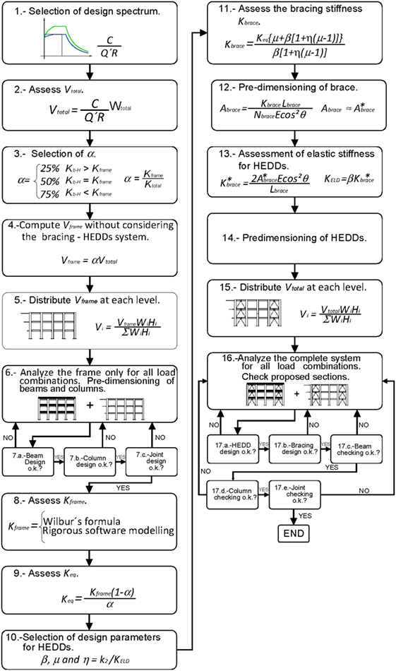
Figure 6. Flow chart synthesizing the code-oriented proposed design procedure for steel moment frames with HEDDs as structural fuses.
The code-oriented design procedure is schematically synthesized in Figure 6 and reported in detail elsewhere (Hernández, 2015). The proposed method is an adaptation for SMRSFs of the design procedure reported for RC-IMRFs in Tena-Colunga and Nangullasmú-Hernández (2015).
It can be observed that for the proposed design method, a preliminary decision is done on the elastic lateral stiffness ratio α, this is, a proportion of the global elastic lateral frame stiffness with respect to the global lateral stiffness of structure (step 3, Figure 6). Then, the design base shear that the moment frame should resist behaving essentially elastic in absence of the bracing-hysteretic device system is computed (step 4, Figure 6) and distributed along the height (step 5, Figure 6). Then, a preliminary design for the frame sections considering vertical loads plus their share of lateral loads in absence of the bracing and the structural fuses could be done (steps 6 and 7, Figure 6). It is worth noting that the proposed α ratio must be checked at all stories (storey shear over story displacement), where cross sections for columns, beams, and braces are changed. The frame must satisfy all serviceability state limits under gravitational loads also.
Once frame sections have been pre-designed, the lateral stiffness for the moment frame (Kframe) could be estimated using any accepted method already available in the literature (step 8, Figure 6). Then, the stiffness of an equivalent global axial element (nKeq) is assessed (step 9, Figure 6), where n is the number of braces required to support the HEDDs. The stiffness Keq considers the elastic stiffness for each brace (Kbrace) and the effective stiffness of the HEDD at the objective maximum local displacement ductility μ, KEFD (Figure 4). A decision should be made about the design parameters for the HEDDs, mainly β, μ, and η = K2/KELD (step 10, Figure 6). The needed elastic stiffnesses for the bracing and the HEDDs are defined based upon these hypotheses (step 11, Figure 6). The bracing is then pre-dimensioned taking into account stiffness (step 12, Figure 6) and strength criteria. An elastic behavior for the braces must be warrant when the HEDDs would develop their maximum displacement ductility μ, designing the braces also to have a reasonable safety factor for buckling (Hernández, 2015; Tena-Colunga and Nangullasmú-Hernández, 2015). Once the braces are pre-designed, the required lateral stiffness of the HEDDs is assessed (step 13, Figure 6) and the devices predesigned (step 14, Figure 6).
Once the preliminary design for all members has been done, an ad hoc elastic analytical model for the whole building is built (step 15, Figure 6), using the equivalent secant stiffness KEFD at the target ductility μ for the HEDD (Figure 4), that should be analyzed again under gravitational loads and the lateral load profile corresponding to the design base-shear (step 16, Figure 6). 3D elastic models were built in ETABS (CSI-2005, 2005) for this purpose. All elements should be revised again for strength and deformation in the described order (step 17, Figure 6) corresponding to a capacity-design approach to warrant a design according to the structural fuse concept: HEDDs first, then braces (weakest HEDDs—strong brace), then beams, columns, and panel zone (weak beam—strong column—strongest joint). The entire structure should also be reviewed to comply with lateral deformations limit states according to code recommendations or other performance objectives. A final check is also needed to evaluate how close are the obtained values of α (particularly at each story where changes of cross sections were proposed) and β (for each HEDDs-bracing) with those initially assumed in the design. If the design procedure is successful, only HEDDs would respond in the non-linear range, having the beams of frames as reserve source of energy dissipation if expected demands are exceeded.
Non-Linear Static Analyses
Non-linear static analyses (pushover) were conducted for each designed model under study using Drain-2DX (Prakash et al., 1992). All elements (columns, beams, braces, and HEDDs) were modeled to monitor the possibility of developing a non-linear behavior, as described in detail elsewhere (Hernández, 2015). Beams and columns (A50 steel) were modeled as beam-column elements with lumped plasticity at element ends and assuming and elastic-perfectly plastic behavior. Beams were modeled as beams type (type 1) and columns as steel columns type (type 2) according to Drain-2DX manuals. Yield interaction surfaces were computed for each cross section using basic plasticity principles for steel elements. Braces (A36 steel) were modeled as truss elements with yielding in tension and elastic bucking in compression. Buckling load capacities were assessed according to NTCEM-04 (2004). HEDDs (A36 steel) were modeled using equivalent beam-column elements connected to the chevron braces and beams, according to a previously validated procedure which is outlined in detail elsewhere (Tena-Colunga, 1997). P-Δ effects were considered in the analyses. For simplicity, lateral load distribution profiles based upon the first mode of vibration were used in the pushover analysis. This was done to have a general framework of comparison, taken into account that: (a) building height ranges from 5 to 25 stories, (b) the modal mass associated to the fundamental mode is higher than 60% for most buildings, and (c) for similar buildings, it was demonstrated (Godínez and Tena, 2014) that modal pushover analysis is not a suitable method to determine average global design parameters for the structural system of interest, which strongly depends on the first mode of vibration. In addition, for this system and for the purpose of assessing global design parameters only, higher mode effects were found to have a reduced impact in assessing peak lateral drifts even for the upper stories, where larger differences are expected when comparing the results obtained with pushover analyses based upon the fundamental mode with those obtained with modal pushover analyses as presented in the literature (i.e., Chopra and Goel, 2002). Peak effective lateral forces were not importantly modified either when considering higher modes. Of course, higher mode effects are very important in the non-linear dynamic response of multi-story and very tall buildings, something which it is out of the scope of the present study.
The principal results obtained from pushover analyses were: (a) normalized story and global lateral shear vs drift curves (V/W vs Δ) and, (b) yielding mapping related to the load step where the collapse mechanism occurred. The following information was processed from the story and global shear vs drift curves: (a) overstrength factors (Ω), (b) ductility reduction factors (Q), (c) apparent peak story and global ductility capacities, (d) equivalent story drift at yielding (Δy), (e) peak story drifts (Δmax).
Mapping of Intensity of Inelastic Responses
A hot color scale was defined to highlight the inelastic demands of all structural elements, as depicted in Figure 7. An elastic response is identified with no color. Non-linear response after yielding and up to a reparable damage state for conventional structural elements is identified with a yellow color (ϕ/ϕu ≤ 0.25), and 1 < μ < 2.5 for hysteretic energy dissipation devices. Orange is employed for moderate non-linear responses, 2.5 < μ < 5 for hysteretic devices and 0.25 < ϕ/ϕu ≤ 0.5 for beams and columns. For important non-linear responses, the red color is used; for beams and columns (up to peak response, 0.5 < ϕ/ϕu ≤ 0.75) and 5 < μ < 7.5 for HEDDs. Brown is used for the non-linear response on the descending branch of moment-curvature curves is identified with the brown color, corresponding to the range 0.75 < ϕ/ϕu ≤ 1.0 for conventional structural elements and 7.5 < μ < 10 for HEDDs. Although the inelastic behavior of braces was considered in all studied models, all braces for all studied models remained elastic during the performed pushover analyses (and non-linear dynamic analyses).
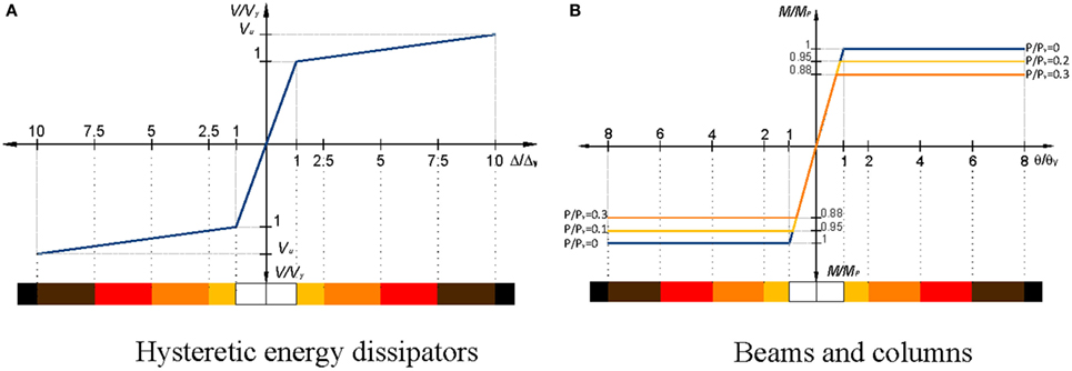
Figure 7. Schematic color intensity scale for the inelastic responses of the assessed moment-normalized curvature curves for HEDDs, beams, columns, and braces. (A) Hysteretic energy dissipators. (B) Beams and columns.
The final yielding mappings related to achieve the target ductility demand (μ ≥ 10) for the most demanded HEDDs for the 15-story and 25-story models when K2 = 0.03KELD for the different values of α and β are depicted in Figures 8 and 9 when θ = 45° (higher demands). For space constraints, the results for other elevations and for θ = 40° are not shown, but coincidences and differences with θ = 45°are also discussed.
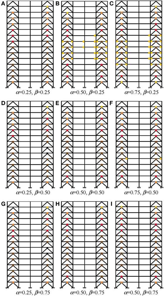
Figure 8. Inelastic demands mapping for 15-story models where θ = 45° and K2 = 0.03KELD. (A) α = 0.25, β = 0.25. (B) α = 0.50, β = 0.25. (C) α = 0.75, β = 0.25. (D) α = 0.25, β = 0.50. (E) α = 0.50, β = 0.50. (F) α = 0.75, β = 0.50. (G) α = 0.25, β = 0.75. (H) α = 0.50, β = 0.75. (I) α = 0.50, β = 0.75.
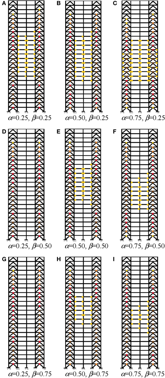
Figure 9. Inelastic demands mapping for 25-story models where θ = 45° and K2 = 0.03KELD. (A) α = 0.25, β = 0.25. (B) α = 0.50, β = 0.25. (C) α = 0.75, β = 0.25. (D) α = 0.25, β = 0.50. (E) α = 0.50, β = 0.50. (F) α = 0.75, β = 0.50. (G) α = 0.25, β = 0.75. (H) α = 0.50, β = 0.75. (I) α = 0.75, β = 0.75.
Completely satisfactory yielding performances (only HEDDs yield) were achieved for the 5-story models for all the considered values of α and β regardless of the value of θ (not shown, Hernández, 2015). Similar results were obtained for the 10-story models when θ = 40° (only HEDDs yield, not shown, Hernández, 2015) and mostly when θ = 45°, except when β = 0.25 for α = 0.50 and α = 0.75, where some incipient yielding (yellow code) was triggered at few beams at stories 3–5 (not shown, Hernández, 2015).
For the 15-story models, completely satisfactory yielding performances are also achieved for all the considered values of α and β when θ = 40° (only HEDD yield, not shown, Hernández, 2015) and mostly when θ = 45° (Figure 8), except when β = 0.25 for α = 0.50 (Figure 8B) and α = 0.75 (Figure 8C), where some incipient yielding (yellow code) was triggered at few beams at stories 5–9. Incipient yielding is also observed at few beams at the fifth story when α = 0.75 and β = 0.50 (Figure 8F).
For the 25-story models, completely satisfactory yielding performances are achieved for all the considered values of α and β when θ = 40° (only HEDD yield) except when α = 0.75 and β = 0.25, where some incipient yielding (yellow code) was triggered at few beams at stories 9–14 (not shown, Hernández, 2015). When θ = 45° (Figure 9), 100% satisfactory performances are only obtained when α = 0.25 and β = 0.50 (Figure 9D) and α = 0.25 and β = 0.75 (Figure 9G). However, very reasonable yielding performances are still obtained for the remaining combinations of α and β granted that incipient yielding (yellow code) could be allowed to beams at middle stories. The intensity of beam yielding increases as β decreases, this is, much more beams yield when β = 0.25 (Figures 9A,C) than when β = 0.50 (Figures 9E,F) or β = 0.75 (Figures 9H,I).
In fact, from the yielding mappings shown in Figures 8 and 9, and those which are not shown due to space constraints but that are presented elsewhere (Hernández, 2015), the following general observations can be made:
1. For a given value of α, inelastic demands at HEDDs tend to increase as β decreases. In fact, as the number of stories increases, some beams start to yield as β decreases.
2. For a given value of β, inelastic demands at HEDDs tend to increase as α increases. In fact, as the number of stories increases, some beams start to yield as α increases.
3. Therefore, as the number of stories increases, the best performances are obtained for the following combination: the smallest value for α and the largest value for β, in this study α = 0.25 and β = 0.75, as it can be confirmed observing Figures 8G and 9G.
4. Also, as the number of stories increases, the worst performances are obtained for the following combination: the largest value for α and the smallest value for β, in this study α = 0.75 and β = 0.25, as it can be confirmed observing Figures 8C and 9C.
5. With respect to the angle of inclination of the chevron bracing from horizontal, it is observed that more beam yielding occurs for θ = 45° than for θ = 40°. Therefore, it seems that as θ increases, the bracing-HEDD become less efficient to prevent beams from yielding. In fact, as θ increases higher axial loads are developed in braces and columns, as well for a given β ratio for the bracing-HEDD system. Therefore, for other structural systems, yielding of columns may also occur, as reported by Tena-Colunga and Nangullasmú-Hernández (2015).
Ductility Demands on HEDDs
To help illustrate the impact of the postyielding stiffness K2 in the ductility demands of the HEDDs, the displacement ductility demands related to the yielding mappings for the 15-story models where θ = 45° are depicted in Figure 10 for the different K2/KELD ratios under study. Similar curves were obtained for all models (5, 10, 20, and 25 stories) and angle of the bracing from horizontal (θ = 40°). In general, as K2 increases, the ductility developed by the HEDDs also tends to increase for all the considered combinations of α and β. As a matter of fact, for an elastic-perfectly plastic assumption (K2 = 0), it is observed that the HEDDs usually develop the smallest ductilities at the medium and upper stories. As β decreases, the differences between elastic-perfectly plastic (K2 = 0) and other bilinear behaviors (K2 ≠ 0) for the HEDDs decreases. In contrast, as α increases, the differences between elastic-perfectly plastic (K2 = 0) and other bilinear behaviors (K2 ≠ 0) for the HEDDs decreases. However, it is worth noting that for the bilinear models under study (K2 = 0.03KELD and K2 = 0.05KELD), similar results (very small differences) are obtained regardless the values of α and β.
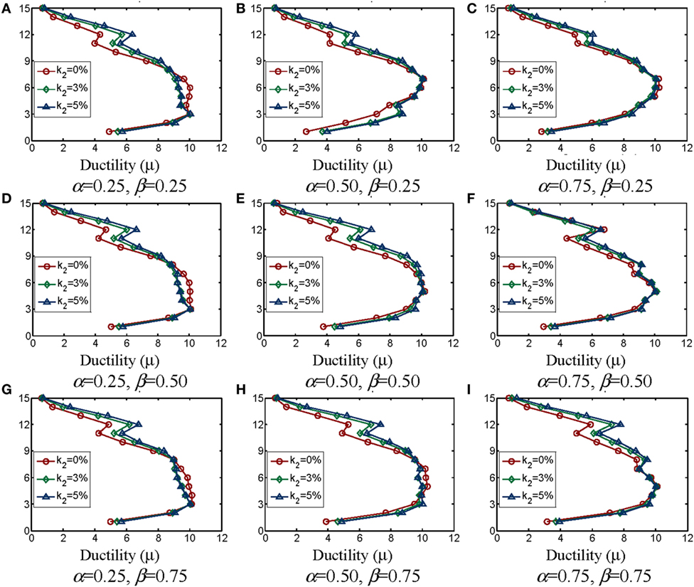
Figure 10. Ductility demands (μ) for the HEDD for 15-story models where θ = 45°. (A) α = 0.25, β = 0.25. (B) α = 0.50, β = 0.25. (C) α = 0.75, β = 0.25. (D) α = 0.25, β = 0.50. (E) α = 0.50, β = 0.50. (F) α = 0.75, β = 0.50. (G) α = 0.25, β = 0.75. (H) α = 0.50, β = 0.75. (I) α = 0.75, β = 0.75.
Why do the ductility demands increase for the HEDDs, as K2 increases? The reason is that since K2 is being directly considered in the design procedure (Figure 4), even though elastic-perfectly plastic (K2 = 0) and the other bilinear HEDDs (K2 ≠ 0) are designed to yield the same ultimate peak force Fu (Figure 4), it can be observed from Figure 4 that the yielding force Fy for the other bilinear HEDDs (K2 ≠ 0) is smaller than for the elastic-perfectly plastic isolators (K2 = 0), so bilinear HEDDs with K2 ≠ 0 ended yielding first than elastic-perfectly plastic HEDDs.
Assessment of Global Design Parameters
Once all inelastic demand mappings and their relation with the ductility demand curves for the HEDDs for all considered models were carefully studied, the information obtained from non-linear static analyses was used to assess global design parameters, as briefly discussed in following sections.
Best Stiffness Ratios
From careful analyses of inelastic demand mappings and ductility demand curves for the HEDDs (i.e., Figures 8–10), presumed “better” or “best” α and β stiffness ratios were defined.
In Mexican codes, Q is defined as the seismic response modification factor used in the design that accounts for the deformation capacity. Therefore, it can be estimated from the global base shear vs global drift idealized bilinear curve as Q = Δu/Δy (Figure 11). Q values were calculated under this definition for all models under study.
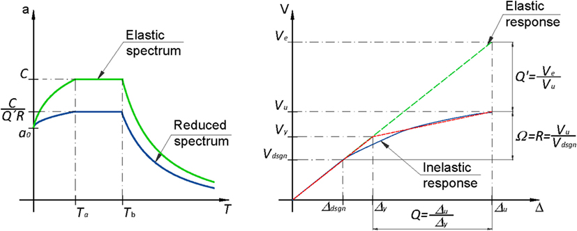
Figure 11. Assessment of the global design parameters Q and Ω assessed from the global base shear vs global drift curve from pushover analyses.
An important effort was made to synthesize in a compact table format the best performances of the models under study taking into account the desirable mechanism of strong column-weak beam, strong bracing—weakest energy dissipation device (structural fuse). The results when θ = 40° and θ = 45° are reported in Tables 1 and 2, respectively, and one may have a clue of the range of application of the parameters under study.
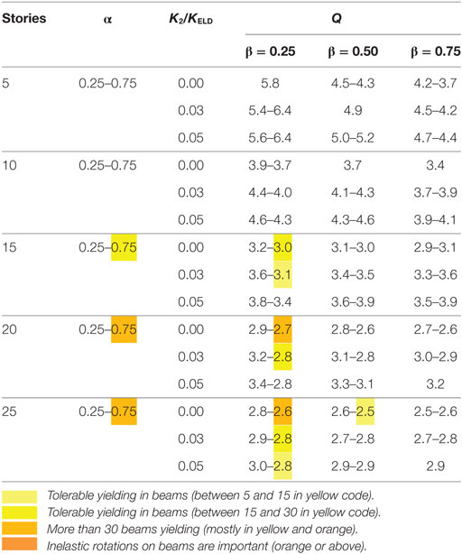
Table 1. Recommended values of the structural parameters when θ = 40°.
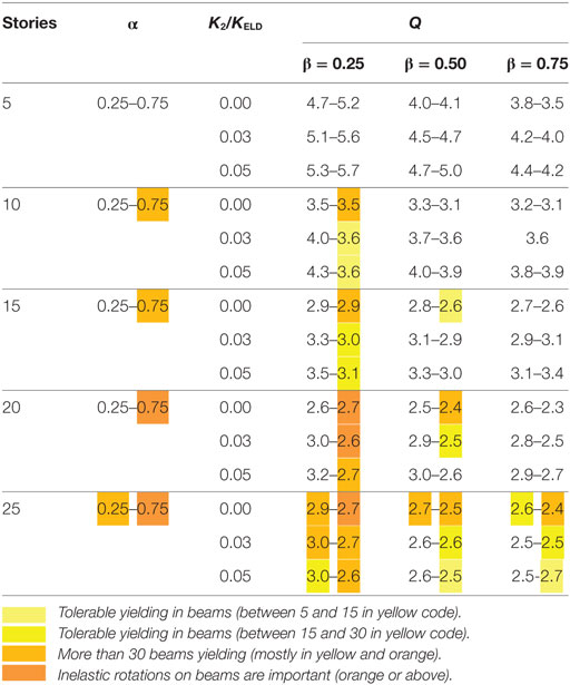
Table 2. Recommended values of the structural parameters when θ = 45°.
In Tables 1 and 2, color shades are used in parameters α, β, and Q to identify the following global behavior: (1) no color shade is employed when there is no yielding in beams and columns or there are few incipient yielding in beams (less than 5 beams ends in yellow code according to Figure 7B), (2) light-yellow shades identify tolerable yielding in beams (between 5 and 15 in yellow code according to Figure 7B), (3) yellow shades identify tolerable but larger yielding in beams (between 15 and 30 in yellow code according to Figure 7B), (4) orange shades when there are more than 30 beams yielding (mostly in yellow and orange according to Figure 7B), and (5) light red shades are employed when non-linear rotations on beams are important (orange or above according to Figure 7B). The color code on parameter α is related to the value where yielding of beams occurs, and it is only marked with the highest intensity for the identified β and K2/KELD combinations, to save space. Also, the first Q value for a given β ratio is related to α = 0.25, whereas the second value is related to α = 0.75.
It can be concluded by analyzing the data summarized in Table 1 that, with SMRSFs which chevron braces which are inclined an angle θ = 40° from horizontal, it is possible to have a wide range of stiffness balances to get a design close to the structural fuse concept. For most considered building elevations (5–25 stories) and for V/W = 0.10, no yielding in beams is possible when θ = 40° for the following ranges: 0.25 ≤ α ≤ 0.75, 0.25 ≤ β ≤ 0.75, and 0.0 ≤ K2/KELD ≤ 0.05; therefore, it could be applied for the whole range. Incipient yielding on few beams (yellow code) is only obtained for the following cases: (a) α = 0.75, β = 0.25, and K2/KELD = 0.0 and K2/KELD = 0.03 for the 15-story models, (b) α = 0.75, β = 0.25, and K2/KELD = 0.03 for the 20-story and 25-story models. Moderate yielding in beams (orange code) is only obtained when α = 0.75, β = 0.25, and K2/KELD = 0.0 for the 20-story and 25-story models.
In contrast, it can be concluded analyzing the data summarized in Table 2 that the range of application of stiffness balances to obtain a design close to the structural fuse concept is notably reduced for SMRSFs when θ = 45° and V/W = 0.10. The concept is widely applicable for all considered combination of α, β, and K2/KELD for models 5 stories in height and most of the 10-story models, except when α = 0.75 and β = 0.25, particularly when K2/KELD = 0.0, where an orange code was obtained. Important yielding of beams starts at the 15-story models when α = 0.75 and β = 0.25. Beam yielding increases for the 20-story models, where important yielding is obtained when: (a) α = 0.75 and β = 0.25 and (b) α = 0.75 and β = 0.50. For the 25-story models, yielding of beams is unavoidable for any combination of α and β, but tends to be smaller as both β and K2/KELD increases. Therefore, from the results obtained and summarized in Tables 1 and 2, it can be concluded that as the number of stories increases, beams start yielding more importantly when the following combination of parameters occur: β decreases, α increases and K2/KELD decreases, particularly when K2 = 0 (elastic-perfectly plastic behavior for the HEDDs). Also, inelastic action in beams considerably increased as the angle θ also increased, despite of the fact that the increment seems very small (5° only).
Seismic Response Modification Factor Q
Assessed seismic response modification factor for ductility (Q) for the α and β stiffness balances under study are identified in Table 1 (θ = 40°) and Table 2 (θ = 45°). It is observed that the largest Q values are obtained for the low-rise models where α = 0.25. It is observed from both Tables 1 and 2 and Figure 12 that Q reduces as: (a) the number of stories increases, (b) β increases, and (c) K2/KELD decreases. The impact of α in Q is not as clear as with the other parameters. In general, Q increases as α increases, but in smaller proportions that with respect to β.

Figure 12. Assessed global ductility factors Q for models with α and k2 variables for α = 0.50 and β = 45°. (A) α = 0.50, β = 0.25. (B) α = 0.50, β = 0.50. (C) α = 0.50, β = 0.75. Assessed overstrength factors for models with α and k2 variables for β = 0.50 and θ = 40°. (D) α = 0.25, β = 0.50. (E) α = 0.50, β = 0.50. (F) α = 0.75, β = 0.50.
According to Mexican codes, the largest Q value for the design of ductile systems is Q = 4. It can be observed in Tables 1 and 2 that larger values of Q are obtained for low-rise models (5-story models). However, smaller Q values are obtained for 10 stories or more if the system is limited to the peak target ductility demand μ = 10 for the HEDDs and the desired limit state corresponds to the structural fuse design concept. Of course, largest Q values could be obtained if severe yielding and damage on beams would be tolerated, but what would be the reason for that?
Seismic Response Overstrength Factor
Assessing suitable overstrength factors for the design of this structural system is very important, because the efficiency of buildings with structural fuses strongly depend on reasonably predicting the peak design yielding forces, in order that structural fuses would start working (yielding) first and then help controlling the dynamic response of the building structure though their controlled inelastic deformation.
Overstrength factors were assessed as Ω = R = Vu/VDesign (Figure 11), where Vu is the peak base shear attained by the structural system from non-linear static analyses when reaching the target ductility demand μ = 10 for the HEDDs, and VDesign (Vdsgn in Figure 11) is the design base shear (VDesign = 0.10 W for all models). The obtained overstrength factors varied from 1.7 ≤ Ω ≤ 2.4 for models where α = 0.25, 2.4 ≤ Ω ≤ 3.0 when α = 0.50, and 3.0 ≤ Ω ≤ 4.0 when α = 0.75 (Figure 12). The most influential stiffness ratio on overstrength is α (Figure 12), because as α increases, the SMRSFs take a bigger share of the lateral load. Therefore, because of the capacity-design procedure outlined before, beams and columns are overdesigned with respect to HEDDs. The second most influential stiffness parameter in Ω is the assumed post-yielding stiffness ratio K2/KELD (Figure 12), as relatively larger overstrength factors are obtained when K2/KELD decreases, being the largest for elastic-perfectly plastic HEDDs (K2 = 0%). The influence of β, θ, and the number of stories on overstrength seems not to have a clear trend for the studied system.
It is worth noting that, as expected, the assessed overstrength factors Ω for SMRSFs with HEDDs are much larger than those obtained for RC-IMRFs with HEDDs (1.35 ≤ Ω ≤ 1.5) by Tena-Colunga and Nangullasmú-Hernández (2015). Higher overstrengths are usually developed in code-design moment-framed steel structures (i.e., Tena-Colunga, 2010; Tapia-Hernández and Tena-Colunga, 2014) than in code-designed RC moment-framed structures (i.e., Tena-Colunga et al., 2008; Godínez-Domínguez and Tena-Colunga, 2010).
Non-Linear Dynamic Analyses
In order to help illustrate that the proposed design procedure is reasonable for strong ground shaking, non-linear dynamic analyses were conducted for the models subjected to artificial records for a postulated Ms = 8.1 subduction earthquake similar to the September 19, 1985, Michoacán earthquake in the lake-bed region of Mexico City (soft soils). Artificial records were obtained for stations installed after the 1985 earthquake where recorded ground motions are usually stronger than the well-known SCT station.
One of these stations is Station 56, located at the Rome District, where many midrise buildings collapsed during the 1985 Earthquake. The artificial S56-EW record and its corresponding response spectra for 2 and 5% equivalent viscous damping is depicted in Figure 13. In the non-linear dynamic analyses, an equivalent viscous damping ratio ζ = 2% was used for all models, as values of ζ ranging from 2 to 4% have been measured experimentally in existing steel buildings. The site period for S56 is Ts = 2.2 s, where it has a peak pseudo-acceleration close to 1.5 g for ζ = 5%, which in fact it would surpass in 25% the peak pseudo-acceleration 1.2 g considered in the elastic design spectrum (Q = 1) for that region in Mexico’s Federal District Code (NTCS-04, 2004), as depicted in Figure 13B. However, if one considers the assumed viscous damping ratio ζ = 2% for the steel structure, the peak pseudo-acceleration is Sa = 2.32 g, which surpass in 93% the design acceleration for the elastic design spectrum (Q = 1), as also depicted in Figure 13B. Therefore, this artificial record is a good test for the 25-story models, which computed fundamental periods ranged from T = 2.14s to T = 2.33 s and, according to NTCS-04, these models should be designed with an effective design base shear V/W = 0.10 for a site with Ts = 2.2 s if Q = 4 and R = 2 are assumed in the design process (Figure 13B).
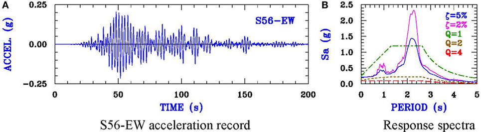
Figure 13. S56-EW acceleration record and response spectra for ζ = 2 and 5%. Elastic and inelastic design spectra for NTCS-04 for a site with Ts = 2.2 s. (A) S56-EW acceleration record. (B) Response spectra.
For that reason, the following 25-story models were considered in the simulations with S56-EW record when β = 0.75, K2/KELD = 0.03 and θ = 45°: (a) α = 0.25, (b) α = 0.50, and (c) α = 0.75. As expected, because of their corresponding inelastic demand mappings obtained from pushover analyses for a target ductility μ = 10 in the HEDDs (Figures 9G–I, respectively), the most demanded model under the action of S56-EW record was the model where α = 0.75, which results would be discussed as follows. The peak inelastic demand mapping obtained from the non-linear dynamic simulation under the action of the S56-EW record for the model where α = β = 0.75 are depicted in Figure 14 and compared with the one obtained from pushover analyses. It is observed from Figure 14A that most of the inelastic action is developed at the HEDDs, which work efficiently, as it can also be observed in the normalized hysteresis curves for each HEDDs depicted in Figure 15. Despite the fact that the response spectrum for the artificial S56-EW record for ζ = 2% considerably surpasses the elastic design spectrum (Figure 13B), the non-linear action in beams is moderate in stories 6–17 (Figure 14A). Therefore, the design procedure was found adequate, as after the capacity of the HEDDs is surpassed by the extraordinary shaking, the next elements that work non-linearly are the beams, as assumed in the proposed capacity-design method. In fact, it can be observed from the pushover results that for this model, beam yielding was expected at intermediate levels (Figure 14B). Also, although magnitudes of peak inelastic demands are different, one can observed that the topological locations of peak demands for HEDDs and beams from the pushover analyses (Figure 14B) reasonably coincide with those obtained from the non-linear dynamic analysis under the action of S56-EW record (Figure 14A). Thus, this fact confirms that for well-designed low-rise and midrise regular buildings with HEDDs under lateral loading, there is a characteristic mechanics of inelastic deformation that mostly depends on the first mode of vibration and less on higher modes and the characteristics of the ground motion. Therefore, if capacity-design methods are used to define clearly the desired yielding sequence of structural elements for an ultimate or collapse mechanism, then pushover analyses based upon the first mode of vibration are reasonable enough to assess global design parameters (ductility capacity, overstrength, drifts, etc.) from a code-oriented design viewpoint for low-rise and mid-rise regular buildings with HEDDs as structural fuses.
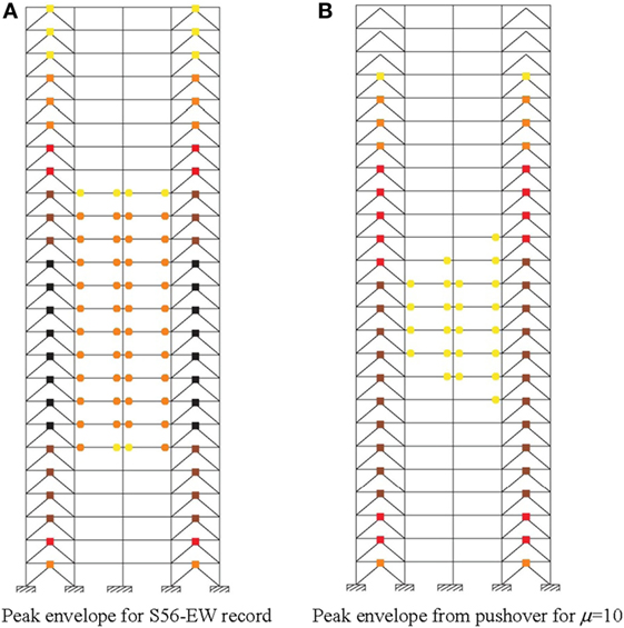
Figure 14. Comparison of peak inelastic demands mapping for the 25-story model where α = 0.75, β = 0.75, k2 = 0.03KELD, and θ = 45°. (A) Peak envelope for S56-EW record. (B) Peak envelope from pushover for μ = 10.
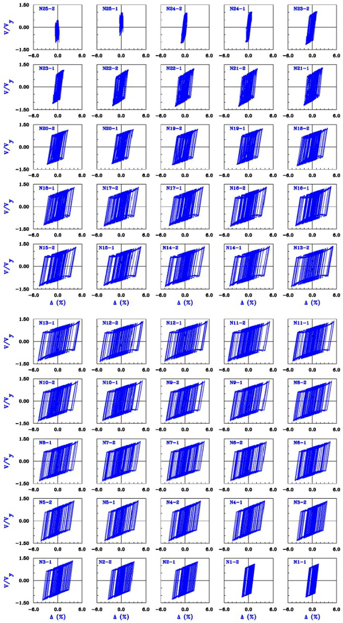
Figure 15. Normalized hysteresis curves for each HEDD of the 25-story model where α = 0.75, β = 0.75, k2 = 0.03KELD, and θ = 45° under the action of S56-EW record.
Finally, it is worth noting that peak story dynamic drifts were near 1% (stories 11–14, not shown) and despite that, the model (Figure 14A) and particularly the HEDDs (Figure 15) dissipate an important amount of energy in a stable way.
Conclusion
Many observations can be made from the extensive and detailed parametric study that was conducted and reported to obtain global parameters for a code-oriented design of buildings structured with SMRSFs with HEDDs. Because of space constraints, only few additional comments from those already available in previous sections are made. From the results of the study one can conclude that an important global ductility capacity for the whole system (Q in terms of Mexican codes) could be achieved for SMRSFs with HEDDs as structural fuses without experiencing important inelastic response in the frame elements (beams and columns) for the whole range of parameters under study: (a) 0.25 ≤ α ≤ 0.75, (b) 0.25 ≤ β ≤ 0.75, and (c) μ ≤ 10.
The following general conclusions can also be drawn for SMRSFs with HEDDs as structural fuses when designed with a code-oriented procedure for a yielding base shear of 10% of the total weight (V/W = 0.10):
1. For a given value of α, inelastic demands at HEDDs tend to increase as β decreases. In fact, as the number of stories increases, some beams start to yield as β decreases.
2. For a given value of β, inelastic demands at HEDDs tend to increase as α increases. In fact, as the number of stories increases, some beams start to yield as α increases.
3. Therefore, as the number of stories increases, the best performances are obtained for the following combination: the smallest value for α and the largest value for β, in this study α = 0.25 and β = 0.75.
4. Also, as the number of stories increases, the worst performances are obtained for the following combination: the largest value for α and the smallest value for β, in this study α = 0.75 and β = 0.25.
5. With respect to the angle of inclination of the chevron bracing from horizontal, it is observed that more beam yielding occurs for θ = 45° than for θ = 40°. Therefore, it seems that as θ increases, the bracing-HEDD become less efficient to prevent beams from yielding. In fact, as θ increases, a higher axial loads are developed at braces and columns, as well for a given β ratio for the bracing-HEDD system.
Non-linear dynamic analyses were helpful to illustrate that the proposed code-oriented capacity-design procedure is reasonable for strong ground shaking typical of soft soils of Mexico City and related to current Mexico’s Federal District design spectra for such sites. Therefore, if capacity-design methods are used to define clearly the desired yielding sequence of structural elements for an ultimate or collapse mechanism, then pushover analyses based upon the first mode of vibration are reasonable enough to assess global design parameters (ductility capacity, overstrength, drift limits, etc.) from a code-oriented design viewpoint for low-rise and mid-rise regular buildings with HEDDs as structural fuses.
Despite the fact that the parametric study was broad and comprehensive, further studies are required from a code-oriented perspective, for example: (a) additional non-linear dynamic analyses for completely code-designed buildings with SMRSFs with HEDDs using the proposed global design parameters in this study when subjected to a comprehensive set of acceleration records typical of soft and firm soils and related to the corresponding soil site and design spectra, (b) a broader range for the design base shear (V/W) and its impact on the studied stiffness ratios and global design parameters, (c) other sections for columns (for example, W sections, which are commonly used in many countries, for example, the United States of America), (d) other structural detailing (non-ductile steel frames) and their impact to the global response, and (e) the impact of the flexibility of the moment connection (partially restrained moment connections).
Author Contributions
HH-R engineered the structural models and carried out the numerical non-linear analyses. AT-C organized the research group, defined the design procedure, and supervised the design of models and numerical non-linear analyses. All authors read and approved the final manuscript.
Conflict of Interest Statement
The authors declare that the research was conducted in the absence of any commercial or financial relationships that could be construed as a potential conflict of interest.
Funding
The National Science and Technology Council of Mexico (Conacyt) granted HH-R an MSc fellowship that is gratefully acknowledged.
References
AISC 341. (2010). Seismic Provisions for Structural Steel Buildings. Standard ANSI/AISC 341-10. Chicago: American Institute of Steel Construction.
ASCE 7. (2010). Minimum Design Loads for Buildings and Other Structures. ASCE Standard ASCE/SEI 7-10. Reston: American Society of Civil Engineers. ISBN 0-7844-0809-2.
Benedetti, A., Landi, L., and Merenda, D. G. (2014). Displacement-based design of an energy dissipating system for seismic upgrading of existing masonry structures. J. Earthquake Eng. 18, 477–501. doi: 10.1080/13632469.2014.897274
Chen, Z. Y., Ge, H., Kasai, A., and Usami, T. (2007). Simplified seismic design approach for steel portal frame piers with hysteretic dampers. Earthquake Eng. Struct. Dyn. 36, 541–562. doi:10.1002/eqe.643
Chopra, A. K., and Goel, R. K. (2002). A modal pushover analysis for estimating seismic demands of buildings. Earthquake Eng. Struct. Dyn. 31, 561–582. doi:10.1002/eqe.144
Ciampi, V., De Angelis, M., and Paolone, V. (1995). Design of yielding or friction-based dissipative bracings for seismic protection of buildings. Eng. Struct. 17, 381–391. doi:10.1016/0141-0296(95)00021-X
CSI-2005. (2005). CSI Analysis Reference Manual for SAP2000, ETABS, and SAFE. Berkeley, CA: Computers and Structures, Inc.
Foti, D., Bozzo, L. M., and López-Almansa, F. (1998). Numerical efficiency assessment of energy dissipators for seismic protection of buildings. Earthquake Eng. Struct. Dyn. 27, 543–556. doi:10.1002/(SICI)1096-9845(199806)27:6<543::AID-EQE733>3.0.CO;2-9
Godínez, E. A., and Tena, A. (2014). Efecto de los modos superiores en la respuesta no lineal de marcos dúctiles de concreto reforzado con contraventeo metálico tipo chevrón, Caso de estudio. Revista Internacional de Ingeniería de Estructuras 19, 171–181; (in Spanish).
Godínez-Domínguez, E. A., and Tena-Colunga, A. (2010). Nonlinear behavior of code-designed reinforced concrete concentric braced frames under lateral loading. Eng. Struct. 32, 944–963. doi:10.1016/j.engstruct.2009.12.020
Hernández, H. (2015). “Propuesta de diseño sísmico para marcos de acero con disipadores de energía histeréticos,” in Tesis de Maestría (México, DF: Posgrado en Ingeniería Estructural, División de Ciencias Básicas e Ingeniería, Universidad Autónoma Metropolitana Azcapotzalco). (in Spanish).
NTCEM-04. (2004). Normas Técnicas Complementarias para Diseño de Estructuras Metálicas, Vol. Tomo II. México, DF: Gaceta Oficial del Distrito Federal. No. 103-BIS (in Spanish).
NTCS-04. (2004). Normas Técnicas Complementarias para Diseño por Sismo, Vol. Tomo II. México, DF: Gaceta Oficial del Distrito Federal. No. 103-BIS (in Spanish).
Prakash, V., Powell, G. H., and Filippou, F. C. (1992). “DRAIN-2DX: base program user guide,” in Report No. UCB/SEMM-92/29 (Berkeley, CA: Department of Civil Engineering, University of California at Berkeley).
Ramírez, O. M., Constantinou, M. C., Kircher, C. A., Whittaker, A. S., Johnson, M. W., Gómez, J. D., et al. (2001). “Development and evaluation of simplified procedures for analysis and design of buildings with passive energy dissipation systems,” in Technical Report MCEER-00-0010 (Buffalo, NY: Multidisciplinary Center for Earthquake Engineering Research, State University of New York at Buffalo).
Ruiz, S. E., and Badillo, H. (2001). Performance-based design approach for seismic rehabilitation of buildings with displacement-dependent dissipaters. Earthquake Spectra 17, 531–548. doi:10.1193/1.1586187
Scholl, R. E. (1993). Fundamental design issues for supplemental damping applications. Earthquake Spectra 9, 627–636. doi:10.1193/1.1585732
Symans, M. D., Charney, F. A., Whittaker, A. S., Constantinou, M. C., Kircher, C. A., Johnson, M. W., et al. (2008). Energy dissipation systems for seismic applications: current practice and recent developments. ASCE J. Struct. Eng. 134, 3–21. doi:10.1061/(ASCE)0733-9445(2008)134:1(3)
Tapia-Hernández, E., and Tena-Colunga, A. (2014). Code-oriented methodology for the seismic design of regular steel moment resisting braced frames. Earthquake Spectra 30, 1683–1709. doi:10.1193/032012EQS100M
Tena-Colunga, A. (1997). Mathematical modelling of the ADAS energy dissipation device. Eng. Struct. 19, 811–821. doi:10.1016/S0141-0296(97)00165-X
Tena-Colunga, A. (2002). “Some aspects on the analytical modelling of metallic energy dissipation devices,” in Proceedings, 12th European Conference on Earthquake Engineering (London, England). CD-ROM, Paper No. 060.
Tena-Colunga, A. (2007). “State of the art and state of the practice for energy dissipation and seismic isolation of structures in Mexico,” in Proceedings, 10th World Conference on Seismic Isolation, Energy Dissipation and Active Vibration Control of Structures (Istambul, Turkey). CD-ROM.
Tena-Colunga, A. (2010). “Seismic response of code-designed medium-rise slender, moment-resisting frame steel buildings in soft soils,” in Proceedings, 9th US National and 10th Canadian Conference on Earthquake Engineering, Reaching Beyond Borders (Toronto, ON, Canada). Paper No. 309, CD-ROM.
Tena-Colunga, A., Correa-Arizmendi, H., Luna-Arroyo, J. L., and Gatica-Avilés, G. (2008). Seismic behavior of code-designed medium rise special moment-resisting frame RC buildings in soft soils of Mexico City. Eng. Struct. 30, 3681–3707. doi:10.1016/j.engstruct.2008.05.026
Tena-Colunga, A., Mena-Hernández, U., Pérez-Rocha, L. E., Avilés, J., Ordaz, M., and Vilar, J. I. (2009). Updated seismic design guidelines for buildings of a model code of Mexico. Earthquake Spectra 25, 869–898. doi:10.1193/1.3240413
Tena-Colunga, A., and Nangullasmú-Hernández, H. J. (2015). Assessment of seismic design parameters of moment resisting RC braced frames with metallic fuses. Eng. Struct. 95, 138–153. doi:10.1016/j.engstruct.2015.03.062
Tsai, K.-C., Chen, H.-W., Hong, C.-P., and Su, Y.-F. (1993). Design of steel triangular plate energy absorbers for seismic-resistant construction. Earthquake Spectra 9, 505–528. doi:10.1193/1.1585727
Vargas, R., and Bruneau, M. (2009). Analytical response and design of buildings with metallic structural fuses, I. ASCE J. Struct. Eng. 135, 386–393. doi:10.1061/(ASCE)0733-9445(2009)135:4(386)
Whittaker, A., Bertero, V. V., Thompson, C., and Alonso, J. (1989). “Earthquake simulator testing of steel plate added damping and stiffness elements,” in Report UCB/EERC-89/02 (Berkeley, CA: Earthquake Engineering Research Center, University of California at Berkeley).
Keywords: metallic fuses, steel frames, stiffness balances, ductility, overstrength
Citation: Tena-Colunga A and Hernández-Ramírez H (2017) Code-Oriented Global Design Parameters for Moment-Resisting Steel Frames with Metallic Structural Fuses. Front. Built Environ. 3:19. doi: 10.3389/fbuil.2017.00019
Received: 12 September 2016; Accepted: 10 March 2017;
Published: 03 April 2017
Edited by:
Luigi Di Sarno, University of Sannio, ItalyReviewed by:
Vagelis Plevris, Oslo and Akershus University College, NorwayStefano Silvestri, University of Bologna, Italy
Copyright: © 2017 Tena-Colunga and Hernández-Ramírez. This is an open-access article distributed under the terms of the Creative Commons Attribution License (CC BY). The use, distribution or reproduction in other forums is permitted, provided the original author(s) or licensor are credited and that the original publication in this journal is cited, in accordance with accepted academic practice. No use, distribution or reproduction is permitted which does not comply with these terms.
*Correspondence: Arturo Tena-Colunga, YXRjQGNvcnJlby5hemMudWFtLm14