- Cyclone Testing Station, James Cook University, Townsville, QLD, Australia
Extensive damage to houses during severe tropical cyclones in the 1970s in Australia highlighted the need for research-based structural engineering principles to be applied in design and construction of houses. Houses have structural redundancies and complex load paths, so the analysis of even simple houses was complicated. In order to evaluate the structural performance of these parallel systems, full-scale house testing commenced at the Cyclone Testing Station (CTS) in the early 1980s with the static multipoint loading of an old house destined for demolition. Following that test program, nine full-scale houses were tested under static and cyclic loading to evaluate load paths in different types of houses with different building practices and materials. Results have been incorporated into amendments of house construction codes, standards, and manuals. Advances in computer modeling and instrumentation have led to more sophisticated full-scale studies. Data on real houses under construction have informed this work and enabled analytical models to incorporate variability in strength of connections in a way that a single test cannot. Progressive failure in the structural systems of timber-framed housing can now be studied to differentiate between houses that have significant damage and seemingly identical ones that have limited damage in the same wind event. These studies involve wind tunnel investigations to determine temporal pressure distributions; full-scale multiple tests on connections (with and without construction defects) to determine statistical distributions of strength and load/deflection relationships; and full-scale tests on houses or portions of houses to determine load sharing mechanisms between parallel structural and non-structural elements. The results of the test programs were used to calibrate the analytical models, which can be used for reliability studies. The paper presents a summary of the methodology and findings from previous CTS full-scale house tests. The results of the most recent research using full-scale tests on a portion of a house and its companion numerical models are discussed and the benefits and limitations of the process outlined.
Introduction
Destructive cyclones including Cyclone Althea (Trollope, 1972) and Cyclone Tracy (Walker, 1975) in Australia in the 1970s highlighted the poor performance of housing in comparison to engineered buildings (e.g., office buildings, commercial premises). Investigations of damage concluded that engineering design was required to improve the safety of house construction. House construction at that time was largely based on traditional building methods that only evolve slowly in response to infrequent but severe events. Since then, engineering principles have been applied to develop Australian Standards used in house design and construction that provide rationally based guidance on resisting wind loads.
Light-framed timber construction is the most common form of residential construction in Australia and North America. This type of construction is characterized by the use of multiple small cross section timber members to create walls, roof, and floors. Light-framed construction developed in the early 1800s with the advent of industrial saw mills that were able to mass produce standard timber sections.
Due to the large numbers of repetitive structural members, a light-framed house is easy to construct but is an extremely complex structure to analyze. The interaction of structural elements result in load sharing, multiple load paths, partial composite action, and under severe wind loading—the non-linear behavior of connections results in load redistribution. Figure 1 shows the multitude of structural elements that can compose a light-framed house, each of these is connected to others with various fasteners each with different structural behaviors.
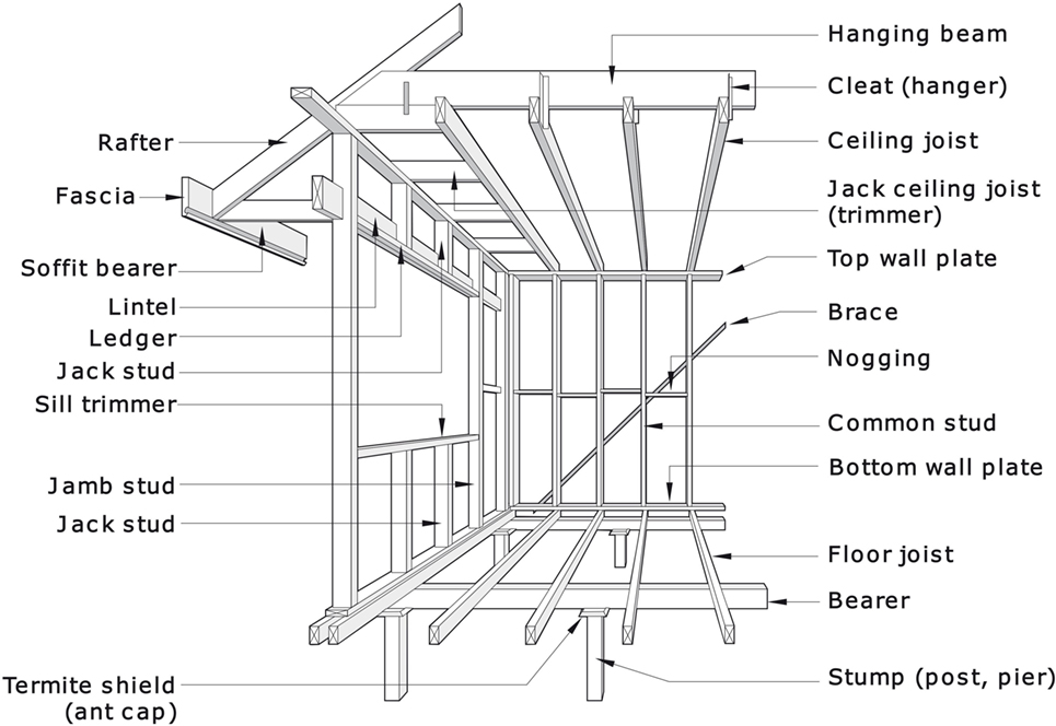
Figure 1. Light framed timber structural system (source: Standards Australia, 2010).
Construction techniques for light-framed construction were largely developed by builders’ and carpenters’ traditions with codified structural engineering principles being implemented in only the last 30 years in Australia. This lack of engineering input along with the high complexity of the structure has meant that houses have been especially vulnerable to severe wind events compared to engineered structures.
Extensive research programs were required to support the rapid evolution of Codes and Standards and required structural models of complete house behavior that had to be verified. The Cyclone Testing Station (CTS) undertook testing on full-scale houses to establish models of load paths and the structural behavior of houses under wind loads. The testing program was used to verify details proposed in a range of deemed-to-satisfy solutions for houses in high-wind areas.
While the initial tests replicated static and repeated applications of patch loads derived from wind-loading standards, the testing program has evolved to include replication of spatial and temporal variations in wind pressures on house surfaces and the combination of full-scale tests and computer models of behavior to model a number of different variations of normal construc-tion practice.
Early Full-Scale Structural Tests on Whole Houses at CTS
Test Programs
By 1980, CTS had undertaken wind load tests on many components of houses in a laboratory setting. However, it was recognized that testing of structural components under simulated wind loads in the correct structural context required full-scale in situ testing. The most appropriate context could be delivered by testing a complete house.
A 40-year-old house that had survived Tropical Cyclone Althea in 1972 was used to test the concept of full-scale tests on houses in 1981. The house was located only 1,500 m from the anemometer that had recorded 52 m/s during the event (Trollope, 1972). The simulated wind loads were applied to the house on site and intended to replicate the loads calculated from the anemometer data. The damage was compared with damage observed on similar houses in the area during TC Althea (Boughton and Reardon, 1982a,b). These tests demonstrated the applicability of full-scale house testing for assessing the interaction of the houses of many interconnected components.
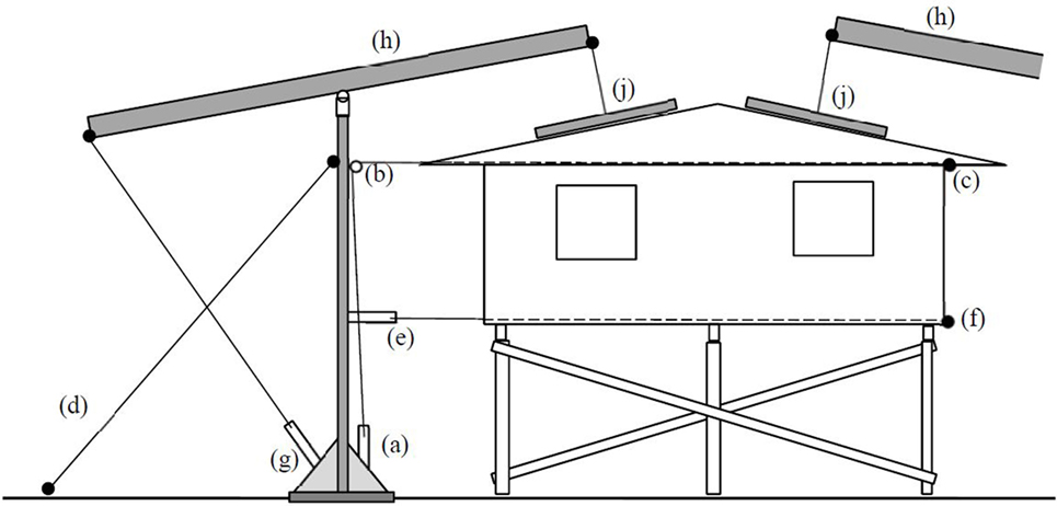
The concept was further developed in 1982 and 1983 when full-scale tests were performed on a new house that had been built to comply with the planned deemed-to-satisfy provisions for suburban houses in tropical cyclone prone areas of Queensland. The house was a rectangular plan 12.8 m × 6.4 m with 10° roof pitch and gable ends. The house was subjected to wind loads calculated from the wind loading standard at the time, AS 1170.2 (Standards Australia, 1983) equivalent to a site wind speed of 42 m/s (Boughton and Reardon, 1983). Figure 2 illustrates the application of:
• Lateral loads at the top of roof level using a hydraulic ram (a) that tensioned a cable passing through a pulley (b) to a load cell and load spreader (c). The reaction was taken through the stay at (d).
• Other lateral loads at floor level could be applied with hydraulic ram (e) that tensioned a cable passing through the floor system to the load cell and load spreader (f). The reaction was also taken by the stay (d).
• Uplift loads to the roof using a hydraulic ram (g) that moved a rocking beam (h) and applied uplift through a load cell and load spreaders attached to the roof battens (j). This loading sys-tem also created a reaction in the stay (d).
Where loads incorporating full internal pressure were applied to the underside of the roof, an equivalent downward load on the floor was created using drums of water to ensure that global loads on the house were representative. Cyclic load simulations were applied to the structure by regulating flow to the hydraulic rams based on the load cell signals. In the early tests, repeated loads at different percentages of the ultimate design wind loads were applied with thousands of uplift cycles and hundreds of lateral load cycles.
Wind forces do not reduce as the house deflects, so wind is very flexible compared with the structures it loads. Therefore, the loading system was designed to be very flexible compared with the house under test by incorporating flexible cables. The measured flexibility of the full-scale loading system was around three times that of the first house constructed for tests. (It was around 10 times the flexibility of later brick veneer houses.)
Displacement transducers that measured vertical and horizontal movement at a number of locations monitored the response of the house. The data were logged on computers. The limitations of early data logging equipment meant that it took 5 s to read all load cells and transducers. The combination of flexible loading systems and slow read times meant that it was difficult to obtain data on loads and deflections near to and immediately after failures. As the full-scale test house testing program developed, the equipment to control loads and monitor deformations became more sophisticated and could achieve more variability in loading regimens and faster response time for measurements.
The tests aimed to identify load paths through the structure under wind loads, identify any vulnerabilities in typical houses built to current standards and develop improved details, and confirm design methods for calculating wind resistance of houses. Each house was loaded with simulated wind loads evaluated from design wind speeds (Standards Australia, 1983) and appropriate for each house. (The houses were designed for a range of wind speeds.)
The following is a summary of complete houses tested in the program during the 1980s and 1990s using the same test equipment:
• The “Hyne house”—a high-set (elevated) house (single storey with floor level 2.4 m above ground), with rectangular floor plan 12.8 m × 6.4 m, a steel sheet roof on hardwood trusses with a 10° pitch and gable ends (Boughton and Reardon, 1983). The house included sawn hardwood timber wall and floor framing, timber floorboards, 6 mm thick fiber cement external cladding, and 10 mm plasterboard internal linings. The design wind speed at eaves level was 42 m/s.
• The “Logan house”—a single storey house with a concrete floor at ground level, a rectangular floor plan 14.2 m × 7.1 m, a steel sheet roof on graded metal purlins with a 2.5° pitch and gable ends (Boughton and Reardon, 1984a). The house included 1.01 m wide prefabricated steel-framed panels (1.15 mm steel stock), clad with 6 mm thick fiber cement externally and internally, and prefabricated ceiling panels with 6 mm fiber cement linings. All panels were bolted together on site. The design wind speed at eaves level was 63 m/s.
• The “Tongan house”—a house designed for a large scale reconstruction program following Tropical Cyclone Isaac in Tonga (Boughton and Reardon, 1984b) (Figure 3) The Tongan house was low-set (single storey with floor level less than 0.9 m above ground), with rectangular floor plan 7.2 m × 4.8 m, a steel sheet roof on softwood trusses with a 26° pitch and gable ends. The house included sawn softwood timber wall and floor framing, plywood floor, 8 mm thick plywood external cladding, and no internal linings. The design wind speed at eaves level was 62 m/s.
• The Brick veneer clad house for construction in tropical cyclone areas (Reardon, 1986)—a single storey slab on ground house of rectangular plan (16.4 m × 7.2 m) with a 15° pitch gable roof clad with pressed metal tiles. The wall frames were constructed from hardwood with galvanized metal straps connecting alternate studs to top and bottom plates. The design wind speed at eaves height was 42 m/s.
• Brick veneer house for construction in non-tropical cyclone areas (Reardon and Mahendran, 1988) (Figure 4)—a house of similar outwards appearance to the cyclonic region house, e.g., slab on ground (16.4 m × 7.2 m). However, the roof structure was pitch frame hardwood construction instead of manufactured trusses and roof clad with concrete tiles. The timber frame walls only had nominal tie down. The design wind speed at eaves height was 27 m/s.
• Light gage steel framed panelized building system for cyclone areas (Reardon, 1990) (Figure 5). The 14 m × 9 m building had 300 mm deep cold formed steel I beams spanning between the long walls to support the roof. A high-tensile rod connected each roof beam at the wall top plate down to a ring beam channel as part of the foundation. The design wind speed at eaves height was 50 m/s.
• Brick veneer split-level house for construction in non-tropical cyclone areas (Reardon and Henderson, 1996). The single storey section had a plan of 8 m × 9 m connected to the two-storey plan of 10 m × 6 m. The test house replicated the new trend of large open plan living areas. The design wind speed at eaves height was 27 m/s.
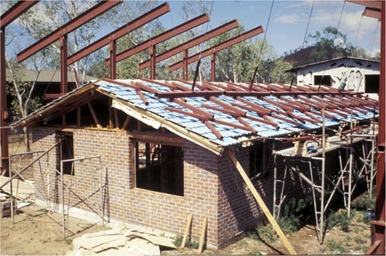
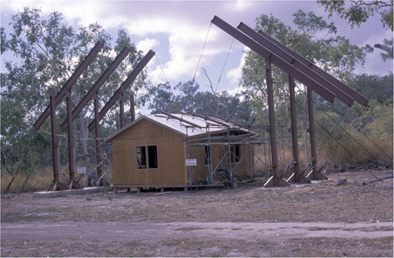
Figure 4. Loading trees attached to roof battens of single storey house (the Hyne high-set house in background showing the damage to exterior wall cladding from simulated wind driven debris to evaluate loss of racking resistance in wall lining).
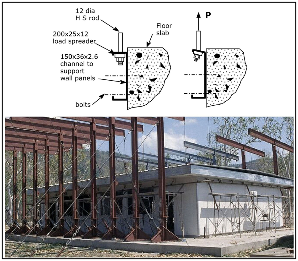
Figure 5. View of light-gage steel-frame house with details of anchorage failures (Reardon, 1996).
Results and Outcomes from the CTS House Testing
Each test series provided tens of thousands of data, which were analyzed to establish load paths for wind forces through the structure of the house, identify vulnerable elements, and provide feedback to designers and Australian Codes and Standards about the resilience and vulnerabilities of housing.
Vulnerable Elements
Leicester and Reardon (2010) postulate that all houses contain one or more elements with significantly less strength than the desired design capacity, through for example, an error in construction or defect material. The full-scale tests confirmed that at least one element/connection in the houses failed at less than the design load. In fact, for each full-scale cyclonic region test building, a loss of strength from low cycle fatigue of a major connection along the load path occurred resulting in the house not being able to achieve its original target design load. After minor changes were made to the vulnerable elements, the modified houses were able to resist the design wind speeds with an appropriate factor of safety:
• The tests on the Hyne house indicated that the vulnerable elements were the batten-to-truss connections and connections of floor to concrete piles. After redesigning those details, the house was able to resist lateral loads that were 140% of the design load and uplift loads that were 200% of the design load.
• The tests on the Logan house showed that the capacity of the metal brackets used in the connections between the roof structure and wall were insufficient, and there was tearing around small washers under bolts between wall panels. After redesigning those details, the house was able to resist lateral loads that were 160% of the design load and uplift loads that were 130% of the design load.
• The tests on the Tongan house showed that some straps and truss nail plates were susceptible to fatigue damage. After redesigning those details, the house resisted loads that were 130% of the design lateral and uplift loads.
• The tests on the brick veneer cyclonic region house again highlighted the issue of loss of strength due to wind load cycles as the roof-to-wall tie down straps weakened and tore. A factor in the unexpected poor performance of the engineered straps was due to the installation requiring the builder to bend the strap from the top plate over the truss and down to the top plate again, which sometimes resulted in one of the straps being sligh-tly looser that the other leading to one side of the strap connection receiving all the load. The testing resulted in changes being made to building standards and construction practice.
• The tests on the panelized engineered building revealed low-cycle fatigue failure of the main tie down system during the simulated wind load cycles. An eccentric tie down detail induced a prying effect on the ends of the high tensile tie down rods resulting in the failure. A redesign of the connection to remove the eccentricity allowed the building to achieve its design load requirements.
The recommended changes to the vulnerable details were given to designers to implement in houses constructed for use in the community. The revised details were also incorporated into relevant Codes and Standards. For example, thousands of the Tongan house design were built during the 1980s and have since survived several tropical cyclones. The success of the Tongan house design through their long-term performance has resulted in a refinement of the design and the construction of more of these houses in 2014.
The tests also showed that, in general, bracing walls in full-scale houses were more vulnerable and less ductile than laboratory tests indicated. In laboratory testing, the reaction frame and the loading system are typically very stiff. First failure of a connection in a bracing wall during laboratory tests typically causes an immediate reduction in load and an effective redistribution to other fasteners. Subsequent increases in load show very ductile behavior of the wall with progressive yielding of the fasteners and an increase in strength of the wall following first fastener failure. However, tests on a house with a flexible loading system and a flexible suspended timber floor system produced complete failure of the bracing walls when the first fastener failed. The energy stored in the floor and the flexible loading prevented release of load and redistribution to the whole panel following first fastener failure. Instead, the adjacent fasteners were rapidly overloaded. The full-scale test bracing capacity of the house was 60% of the capacity taken from the sum of individual bracing walls tested in laboratory conditions (Boughton, 1988).
Load Paths
Load paths for both lateral and uplift loads through the structure were identified by comparing results of each house loaded at a number of stages during construction. The increase in stiffness at each stage of construction gave an indication of the change in load path with the addition of each structural and non-structural element. (An example is plotted in Figure 6 for the two-storey section of the brick veneer split level house.) The results of tests on all houses showed that some non-structural elements were effective in transferring wind loads through the structure. For example, on most houses, without the cornice, the lateral load transfer between the ceiling diaphragm and the top of bracing walls followed a circuitous path: ceiling to ceiling screws, to ceiling battens, to lower chords of trusses, to truss-to-wall connections, to the top of exterior walls, to frame-to-frame nailed connections, to internal bracing wall frames, and then through cladding fasteners to the bracing panels. After the installation of cornices, the load path was from the ceiling cladding through the cornice directly to the bracing panels; a very direct and stiff load path. Therefore, where glued cornices had been installed, almost no lateral load was transferred through the structural connections until the cornice cement had broken.
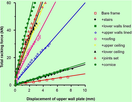
Figure 6. Increase in horizontal displacement of top plate of upper storey with each additional construction stage (Reardon and Henderson, 1996).
Many load paths included a number of parallel elements that had the capacity to share loads if one element failed. Therefore, weaker elements in load paths that incorporated redundancy did not pose a risk of significant structural damage. The vulnerable elements identified in Section “Vulnerable Elements” were not part of a system that allowed alternate load paths or redundancies. This highlighted the need for further research into the structural redundancy of elements in houses and the progression of failure following first failure of a vulnerable element.
Models of Structural Load Transfer in Houses
The results from each series of tests on a house type were able to confirm or refine accepted models of load transfer between elements. For example:
• Tests on brick veneer houses indicated that uncracked brickwork carried all of the lateral wind loads without transferring any loads to the timber frame. However, when the brickwork cracked, the brick ties transferred the load from the brickwork to the timber frame until they buckled and allowed the bricks to touch the frame and transfer load by bearing.
• Tests on bracing walls indicated that in spite of their more brittle behavior indicated in the Section “Vulnerable Elements,” the high in-plane stiffness of roof and ceiling diaphragms enables load sharing between the bracing walls and delivers adequate total bracing capacity. This confirmed the load transfer model assumed in the design of bracing systems in Australian framed houses.
Limitations of Early Tests on Full-Scale Houses
In many of the full-scale tests, particular care was taken to ensure that correct construction practices were used. However, slight variation in design, workmanship, and materials has been observed in inspections of houses in the community and is one of the factors accounting for differences in the performance of similar houses in the same wind event. The cost of building full-scale test houses prevents using this method to test variations in construction practices; however, damage investigations show that this is still a major cause of house failures under wind loads.
The CTS-simulated wind loading across the building is an approximation of the pressure gradients derived from Standards or wind tunnel models. The patch loads and line loads are applied to the structure such that higher loads can be applied to edge regions compared to the field (middle) of the roof. The loads can also be cycled in a sinusoidal application. Although this simulated loading can be repeatedly applied to the test house following change of materials/components, it cannot replicate the spatial and temporal variations from aerodynamic loading, such as the full-scale testing discussed by Huang et al. (2009).
No new complete full-scale test houses have been built at the CTS since the late 1990s with the intervening two decades of research and development targeting the performance of components within the structural models identified in the full-scale house testing program. Recent research has extended the original concept of full-scale testing so that a range of component characteristics can be investigated in tests of full-scale sections of houses.
Full-Scale Tests on House Roofs
Recently, several other full-scale house tests have been carried out to evaluate the structural response and load sharing of the North American and Canadian residential houses (Datin and Prevatt, 2007; Morrison, 2010; Canino et al., 2011; Doudak et al., 2012; Henderson et al., 2013). However, the usefulness of these experimental results to assess the structural response and load sharing of Australian residential house is limited, as their construction types are different. These variations in construction result in differences in their structural response and stiffness of roof-to-wall connections. Thus, it can be expected that the load sharing and reaction influence coefficients will be different in the Australian timber-framed structure compared to that of other countries’ houses.
Based on the applied loads and displacements, the full-scale tests at the CTS (Boughton and Reardon, 1982a,b, 1983, 1984a,b; Reardon, 1986, 1990; Reardon and Mahendran, 1988; Reardon and Henderson, 1996) qualitatively showed the strength, stiffness, and load transfer of the house system subjected to wind load. These tests did not investigate the significance of reaction influence coefficients on the truss-hold down force. The reaction influence coefficient is used with wind pressure distribution to evaluate the truss hold-down forces of timber-framed houses (Ginger et al., 2000). The study presented in this section describes a full-scale test conducted to identify the load sharing and reaction force influence functions of timber-framed houses in Australia. A combination of; full-scale tests on sections of a house, numeric models, characterization of the variability of components, and detailed wind tunnel loading data has been used to investigate structural behavior of houses with a variety of construction practices, determine statistical distributions of strength and load/deflection relationships and load sharing mechanisms between parallel structural and non-structural elements (Satheeskumar et al., 2016a,b).
Data on houses under construction (see Investigation and Testing of Contemporary House Construction) have been incorporated into analytical models to represent variability in the strength of connections in a way that a single full-scale test cannot. The focus of these studies is the investigation of the effects of defects in individual connections and the mechanics of progressive failure in the complex structural systems in timber-framed housing. The results of the test programs were used to calibrate the analytical models, which can be used for reliability studies.
This section discusses research projects that extend the previous CTS full-scale testing programs to evaluate the performance of full-scale roof structures under wind load using a combination of wind tunnel pressure records and full-scale testing of components and assemblies.
Investigation and Testing of Contemporary House Construction
As a collaborator in the Climate Adaptation Engineering for Extreme Events Cluster (CAEx) (Stewart et al., 2016), CTS undertook surveys of houses under construction in three Australian capital cities to document current design and construction practices. The surveys recorded data on structural members (size, grade, and span), connections (fasteners, spacing, and configuration), and identified inadequate design and installation of some elements. Incorrect site classifications for wind, errors in connections for tie-down of roof structural elements, over-driven nails on bracing elements, and incorrect window and door installation were observed. The plans of the inspected houses showed that their roof structure was more complex than the roofs of houses used in previous CTS tests on full-scale houses or in wind tunnel studies to derive peak wind pressures.
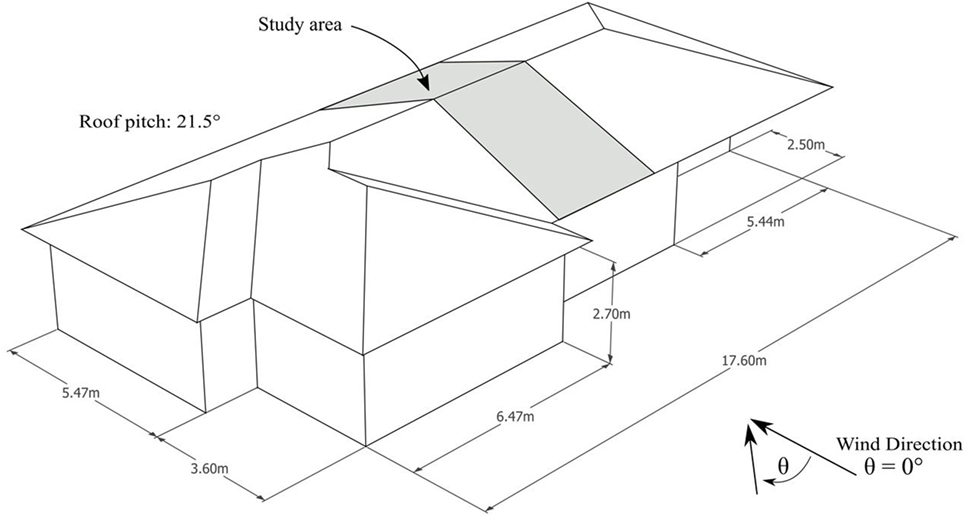
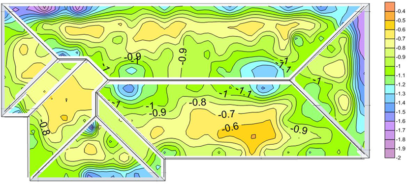
Cyclone Testing Station used these data from the surveys to develop a design of a representative house with specified dimensions, roof shapes and pitch, plan footprints, materials, and structural systems as shown in Figure 7. It included a non-rectangular floor plan with hips, valleys, and short ridges. Wind tunnel studies on this representative house were used to establish base-line peak pressure coefficients on all areas of the roof, as illustrated in Figure 8. Pressure taps were installed on the models in a 12 mm × 18 mm grid-pattern (representative of the 600 mm × 900 mm truss-batten spacings in full-scale) to enable cladding loads, batten-truss loads, and the resulting wind load effects on the trusses to be determined.
Cyclone Testing Station has also conducted investigations of damage to houses following most major wind events in Australia since the mid 1980s. The data from these investigations have been used to highlight/identify deficiencies in design and construction practices that have contributed to changes in Codes and Standards and initiated research projects to improve building resilience. Many of the deficiencies in structural details that contributed to damage in houses during severe wind events were also observed in the CAEx surveys. These deficiencies have been incorporated into recent full-scale tests in order to establish their role in progressive failure and investigate whether redundancies in some elements provide alternative load paths around the deficiencies.
Behavior of Truss-to-Wall Connections
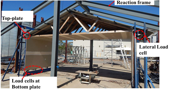
A 3.3 m-long section of house including five 6.6 m-long roof trusses, shown in Figure 9, was constructed for full-scale testing to evaluate the capacity of normal house components such as wall linings and cornices to carry loads (Satheeskumar et al., 2016a) around weak truss-to-wall connections. Vertical load transfer through the structural connections was measured at the top plate and the bottom plate. The full-scale test structure included five standard prefabricated nail plate trusses, metal battens, corrugated steel roof cladding, timber wall frames, plasterboard wall and ceiling lining, and cemented ceiling cornices.
Hand-nailed metal framing anchors that complied with recommended construction practices (“ideal”) were initially installed to connect the trusses to the wall frames. Some of the connections were altered (e.g., missing nails) for subsequent tests to reflect poor construction practices observed in some houses as discussed in the Section “Investigation and Testing of Contemporary House Construction.” The results showed that the load distribution of uplift forces was a function of the stiffness of the roof-to-wall connection. The lining elements (i.e., ceiling, ceiling cornice, and wall lining) contributed significantly to vertical load sharing.
A 3D finite element model (FEM) was also developed using ABAQUS (6.12-3) (ABAQUS, 2013) to further assess the load sharing and structural response of the timber-framed structure to different construction defects in roof-to-wall connections. The connections were represented in the FEM as either linear or non-linear spring elements. The connection forces in the FEM analysis were compared with measurements from full-scale structural testing using uniformly distributed loads. The results were similar, with a maximum variation of about 15% (Satheeskumar et al., 2016b). The validated FEM provided confidence to investigate the response of roof-to-wall connections to more realistic uplift forces that vary across a house roof.
The FEM was developed and analyzed for three different configurations: case 1 using “Ideal” connections; case 2 with a single nail missing in one of the truss tie-downs; case 3 with two nails missing from one truss-to-wall connection and one nail missing from an adjacent truss-to-wall connection. The force displacement relationships for these cases were obtained from the experimental tests and high resolution FEM of isolated connections (Satheeskumar et al., 2016c,d).
Table 1 presents the CN (i.e., truss hold-down coefficient) at each connection when 1 kPa uniform suction pressure was applied on the roof. It shows that the loads in connections adjacent to the trusses that have defective tie-down are increased by about 10% where there is only one defective tie-down (case 2). This figure is significantly less than the 50% redistribution from a statically determinate system. There is a higher load transfer if there are two adjacent defective connections. The research project demonstrated that the linings in normal house construction can carry load around defective truss-to-wall connections.

Table 1. CN of truss-to-wall connections with uniform suction pressure 1 kPa applied to the roof with trusses affected by defective fasteners highlighted.
Progressive Failure and Load Redistribution of Batten-to-Truss Connections
Full-scale house testing conducted in the 1980s and 2015 examined the complex load paths, the effects of construction defects, and damage. However it is still largely unknown how loads are redistributed during a failure and how structural failure can propagate through the roof structure. Damage investigations have shown that the failure of a few batten-to-truss connections can trigger a progressive failure resulting in the loss of large sections of the roof structure.
The study presented in this section examines progressive failures of nailed timber batten-to-truss connections. Laboratory tests were conducted to determine the behavior of connections under wind loads. Wind tunnel studies were conducted to determine the correlation of load time histories at neighboring batten-to-truss connections and its effect on the initiation of a progressive failure. Finally, non-linear structural analysis was undertaken to determine how loads are redistributed as connections fail under uplift loads.
Behavior of Batten-to-Truss Connections
Laboratory tests were conducted on new batten-to-truss connections and on connections taken from 50-year-old houses. The tests on 50-year-old connections provided data on the performance of nailed connections in service and enabled deterioration due to age to be quantified.
Static testing of batten-to-truss connections was conducted to determine the mean strength of the connections under slow load rates (2.5 mm/min as specified in Standards Australia, 2001). A representative load/deflection plot of a 50-year-old con-nection with a strength close to the mean strength is shown in Figure 10. The 50-year-old connections showed a much greater variability in strength than new connections.
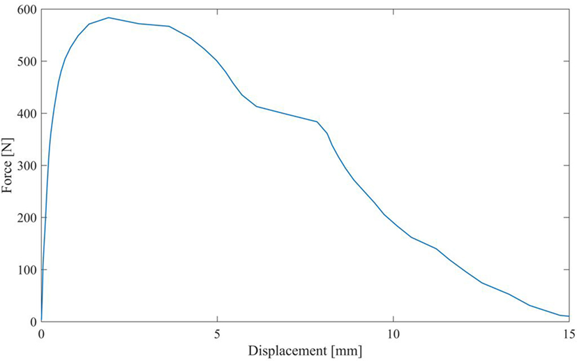
Figure 10. Example of a force vs. displacement curve for static pull-out test of batten-to-truss nails.
Dynamic tests of single batten-to-truss connections were undertaken to characterize progressive failure or deterioration of connections under fluctuating wind loads. The connections were tested using a servo hydraulic universal testing machine with a synthetic test load trace based on the wind tunnel study discus-sed under Section “Investigation and Testing of Contemporary House Construction”. Appropriate time scaling was applied to determine the required full-scale frequency.
Dynamic testing applied repeated synthetic peak loads to full-scale specimens until failure. The loading rate and frequency of the time history signal was based on a gust wind speed of around 40 m/s for a nominal tributary area for the connections of 0.36 m2.
The results of the dynamic tests still showed large variability in connection performance, with some connections able to survive only two or three peaks and some able to survive more than 100 peaks. All showed some ductility as they were able to sustain loads at deformations much higher than their elastic limit.
Figure 11 shows an example of 50-year-old connection behavior under dynamic loading. There was nail slip with each peak event. In most cases, there was an increase in performance similar to strain hardening behavior in steel; the magnitude of each slip decreased near the center of the plot. After the accumulated nail slip had reduced the depth of embedment to a critical level, the connection rapidly lost strength and failed as shown at the right hand side of the plot.
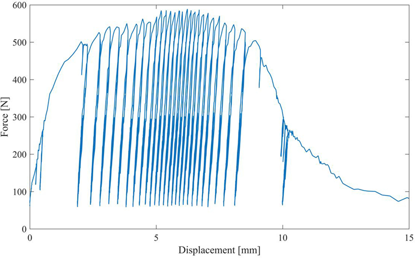
Figure 11. Example of a force vs. displacement behavior of batten-to-truss nails connections under repeated wind uplift peak events.
Preliminary testing also showed that for many of the 50-year-old connections, some nail slip occurred at peak loads below the mean connection strength. The accumulation of nail slip over a number of peak load cycles resulted in lower depth of embedment of the nail into the truss. This observation is compatible with older connections in service that have experienced nail slip in a num-ber of previous wind events failing at loads lower than expected.
The dynamic tests showed that a connection’s elastic stiffness, indicated by the gradient of the loading and unloading paths, does not change with accumulated damage through successive peak events, i.e., the elastic behavior of the connection is similar for each peak load event. This indicates that load redistribution to adjacent connections occurs due to total nail slip in a connection rather than to a decrease in elastic stiffness. Once a connection fails completely, load will be rapidly redistributed to adjacent connections.
The next phase of this study will involve the construction of a full-scale portion of a roof with full instrumentation of each batten-to-truss connection to evaluate the redistribution of load during progressive nail slip and complete connection failure of a single batten-to-truss connection.
Wind Tunnel Time-History of Loadings on Roof Elements
Previous CTS full-scale testing had focused on demonstrating that deemed-to-satisfy designs could withstand the design wind loads and that models of structural behavior were valid, so loads calculated from contemporary wind loading standards were used. However, the Standard loading model is generalized. In order to use full-scale testing to evaluate progressive failure of elements within a house and demonstrate load sharing among elements close to the cladding, as noted in Section “Early Full-Scale Structural Tests on Whole Houses at CTS,” it is important to replicate the temporal and spatial variations in wind loads. Wind tunnel studies were used to create fluctuating load sequences that could be used to simulate wind forces on crucial elements of houses.
Boundary layer wind tunnel studies were conducted on 1/50 scale models to determine pressure distributions on the surface of houses for multiple wind directions (Parackal et al., 2016). Pressures were measured using hundreds of pressure taps on roof and wall surfaces. These pressures were integrated to calculate loads on connections supporting different areas of roof surfaces.
The tributary areas of batten-to-truss connections experienced the highest peak loads at roof corners and the apex of gables. The loads on a single connection were evaluated by summing the pressures over the tributary area of the surface for a single batten-to-truss connection. These loads were characterized by “peak events” of load more than 3.5 SDs from the mean lasting about 0.5–2.0 s for a mean wind speed of 100 km/h at full scale. The peak loads experienced varied with wind directions and were due to different aerodynamic mechanisms such as separation of flow or vortices entrained in the airflow.
In order to determine the factors that may promote failures to progress through a full-scale roof, correlation coefficients of load-time histories at connections were evaluated. The cross-correlation coefficient (rij) defined in Eq. 1 gives a measure of how well correlated the pressures on a specified connection (i) are with the pressures on an adjacent connection (j). A time lag term (τ) is incorporated to allow for the time it takes for a gust vortex or eddy to move from one connection to another:
where and are the fluctuating components of the pressure at locations i and j, σp is the SD of fluctuating load, and T is the time over which the signal is analyzed.
As shown in Figure 12, cross-correlations of time histories show that peak loads are correlated with pressures on adjacent connections. The negative lag times indicate that the pressure is well correlated with pressures on an upwind connection. For this wind direction, it was the connection on the same batten immediately upwind of the connection being evaluated. For other wind directions, the correlations indicated that the peak loads had been moving diagonally across the roof. It was also found that wind directions that caused the highest loads were not necessarily those that caused the highest correlations amongst adjacent connections.
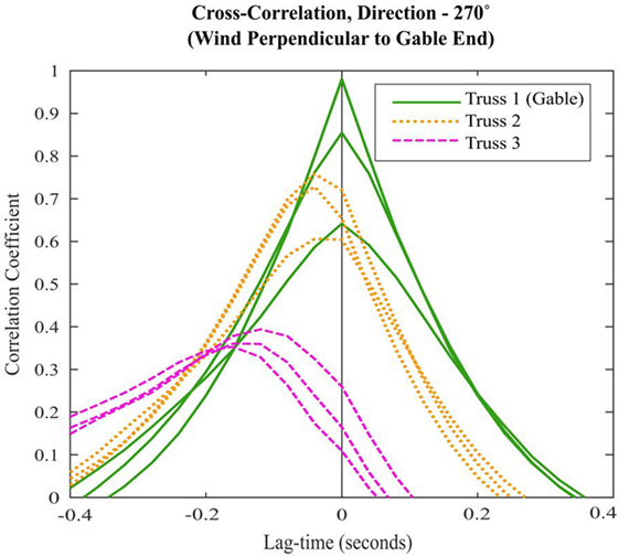
Figure 12. Cross-correlations of time histories. Different lines within each color refer to different batten-to-truss connections on each truss. Truss 1 is over the gable, then, Truss 2 is one truss spacing from the gable, then Truss 3.
The patterns of correlation can have implications on the initiation of progressive failures, especially if the correlation patterns align with the direction in which loads will be redistributed when a single connection fails or weakens. The direction the loads are redistributed between batten-to-rafter/truss connections is determined by the ratio of the bending stiffness of the battens to that of the cladding in the direction parallel to its corrugations as well as the batten and rafter/truss spacing. For example, the gable roof house studied may be most susceptible to progressive failures for wind direction 270° with the correlation patterns aligning along rafter lines and if the bending stiffness of the corrugated cladding is greater than the battens.
Non-Linear “Pull-Up” Analysis
To determine the direction loads are redistributed and to determine how progressive failure may propagate through the roof structure, a non-linear time history analysis using a finite element method structural analysis model was performed. An array of batten-to-truss connections representing the connections within a study area of a gable roof house was modeled as shown in Figure 13. Roof cladding is modeled as a thin shell with the thickness selected to give the same flexural rigidity (EI) as a 0.42 BMT “custom orb” cladding profile. A “stiffness modifier” of 0.1 is applied to EI of the sheeting in the direction parallel to the battens to represent the lower bending stiffness in the direc-tion perpendicular to the cladding corrugations. Battens were modeled as frame elements that represent 45 mm × 70 mm MGP10 battens. Batten-to-truss connections were modeled as multi-linear plastic link elements, with their force–displacement behavior determined from laboratory tests. These links are assigned a proportional limit 0.5 kN, plastic deformation for 10 mm at 0.5 kN, and complete failure at 15 mm extension. The roof structure below is not modeled.
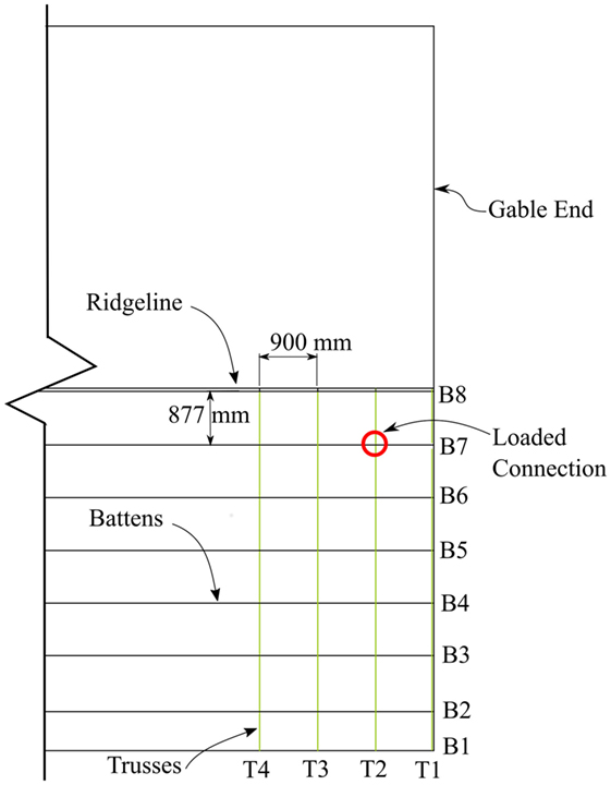
Figure 13. Plan view of batten-to-rafter connections on the gable roof house modeled in the finite element model.
A non-linear time history analysis was performed with a quasistatic ramp load (1 kN/min) applied at the location of connection T2-B7 (batten 7 fastened to truss 2 as shown in Figure 13). The ramp loads are continued as the first connection fails and a cascading failure takes place. Selected time steps of color scale plots showing the redistribution of load are shown in Figure 14.
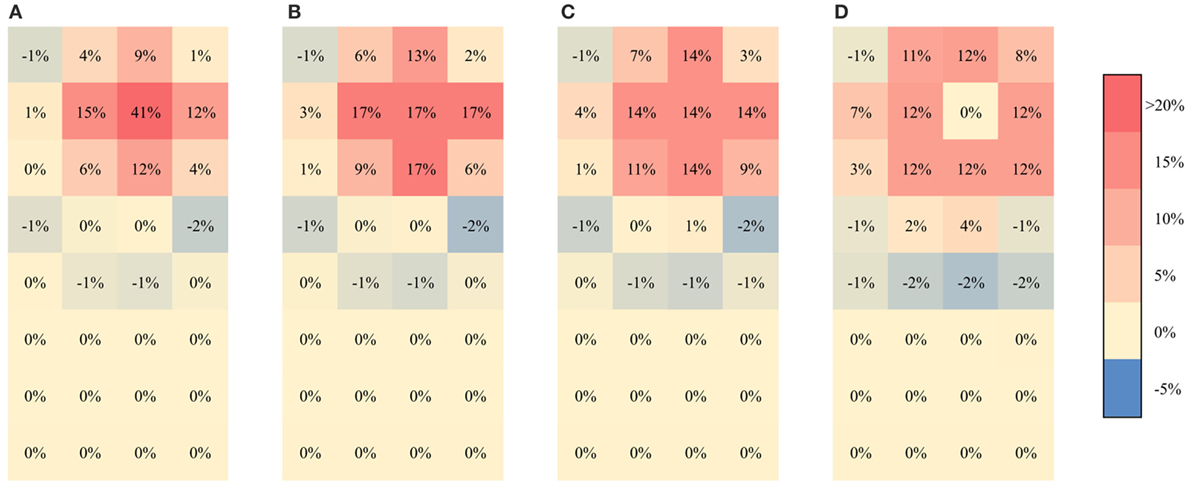
Figure 14. Color scale plots of batten-to-truss connection loads at five time steps showing percentage of total load borne by each connection. From left to right: (A) at and before yield of loaded connection, (B) at yield of connections along battens, (C) at yield of connections along cladding corrugations, and (D) at failure of loaded connection.
As load is applied above T2-B7, the system behaves as a set of springs in parallel, with part of the load being resisted by the connection T2-B7 itself and the remaining resisted by the batten and the cladding in flexure as well as extension of the neighboring connections. Uplift loads are thus shared among neighboring connections even when T2-B7 is undamaged and in the elastic range.
Before connection, T2-B7 yields as shown in Figure 14A, a total of 27% of the load is shared among connections immediately to the left and right on the same batten (T3-B7 and T1-B7). Load is also resisted along the corrugations of the cladding, with a total of 21% shared with connections T2-B8 and T2-B6. Finally, 15% is shared among connections diagonally away from the loaded connection. One hundred three percent of the uplift load is resisted by connections in the 3 × 3 grid surrounding the loaded connection with connections outside of this grid having the sheeting pressing down on the batten (the remaining −3% of loads). These proportions of load sharing continue to the point where connection T2-B7 yields.
After connection T2-B7 yields, the proportion of load borne by this connection decreases and the amount of load sharing at all neighboring connections increases. When the connection to the left (T3-B7) yields, a total of 37% of load is taken by connections that are immediate neighbors on the same batten and 28% spans along corrugations. As the connection to the right (T1-B7) yields, the battens have reduced the proportion of load sharing and bear 34% of the load, as shown in Figure 14B. Loads are now redistributed along corrugations and connections T2-B8 and T2-B6 take 30% of the load. From this point on, the loads borne by connections on the same batten reduce and load transferred along corrugations increases.
Once all connections adjacent to the loaded connection yield as shown in Figure 14C, load is shared equally among all the connections in the 3 × 3 grid including the loaded connection. However, when the loaded connection fails completely as shown in Figure 14D, loads are equally shared among battens and along corrugations. At this stage, loads are redistributed to diagonal connections.
The next connection to fail completely is T1-B7, to the right of the loaded connection. Loads are again redistributed to connections along the corrugations. At this stage, a cascading failure commences with loads being rapidly redistributed as connections fail in rapid succession resulting in the failure of all the connections in the study area.
The non-linear analysis has shown that load sharing and redistribution between batten-to-rafter connections is a complex process. Loads are shared among neighboring batten-to-truss connections depending on the ratio of stiffness of the battens and cladding as well as the batten and truss spacing. Additionally, the load path changes whenever a connection yields or fails completely. Connection failure and load redistribution occurs rapidly but in durations similar to pressure fluctuations experienced on the roof surface. Thus, the correlations of wind pressures may play a significant role in the initiation of a progressive failure. In future work, time history analysis with spatial and temporally varying loads can be used to determine the effects of the load correlations. This will lead to a study of the propagation of the failure cascade as well as how the structural system responds under fluctuating dynamic loads. Similar techniques can be applied to other connections in the vertical load path such as roof-to-wall connections discussed in Section “Full-Scale Tests on House Roofs.”
Discussion of Benefits and Limitations
The original house testing research program at CTS was able to demonstrate the strengths and weaknesses of contemporary house design and enabled the validation of structural details and prescriptive standards (codes) for Australian housing. Typically, once any weak links in the load path were found and repaired, the test houses were stronger than design expectations. The test program led to a greater understanding of the transfer of load and distribution of forces through the various elements of the house structure—the program repeatedly highlighted the complex non-engineered load path of typical house construction. Also, through the application of repeated load cycles representing the duration of a tropical cyclone, issues of low-cycle fatigue on structural connections of light gage steel were highlighted.
In recent years, full-scale testing of US and Canadian houses subjected to wind loads has been conducted to evaluate structural and component response (Datin and Prevatt, 2007; Morrison, 2010; Canino et al., 2011; Henderson et al., 2013). However, there are only limited data available on the load distributions in inter-component connections, and progressive damage due to connection failure to wind loading.
However, full-scale test programs are expensive and time consuming. In early full-scale tests, the costs were justified by the value of these data and outcomes from each test. The current full-scale test program incorporates detailed FEA modeling during the experimental design to ensure that the load and displacement data are recorded for the locations required to best assess the FEA models. Using a validated model, changes in material properties and construction defects can be analyzed with confidence.
Full-scale studies on houses and parts of houses have identified a number of elements that provide structural redundancies. For example, grid systems in roof structures can bridge over weaknesses in specific elements. Wall systems also incorporate multiple parallel elements that can also share load. In addition, there are many non-structural elements such as plasterboard wall linings and ceiling cornices that can also transmit loads around structural systems if the primary structural system fails. However, that does not mean that there is enhanced resilience for all criti-cal elements in the tie-down chain.
The most recent full-scale tests indicate that battens and roof cladding provide some bridging between batten-to-rafter/truss connections. Battens have the potential to carry the load from a failed batten-to-truss connection to only the adjacent connections along the batten. This study also indicates that the roofing provided a stiffer load transfer mechanism that only transfers load in a direction perpendicular to the ridge of the roof. However, in completed buildings, a failure of an edge batten-to-truss connection at the eaves could transfer load via bending in the battens to the fasteners in the same batten or via cantilever bending of the roof sheeting to the batten connector on the next batten up the roof. The load transfer from the failed connector significantly increases the load on the adjacent fasteners and can lead to progression of the failure. Where first failure is near a corner of a roof panel, there can be a rapid spread of failure through the roof in both directions.
Connections deeper within the tie-down load path have greater redundancy and resilience than connections immediately under the roof cladding. Recent tests indicate that at lower levels in the house, many more elements have the potential to provide bridging systems that can transfer load to other elements if a connection fails. Roof sheeting, battens, ceiling elements, ceiling cladding, and other roof structural elements can transfer load laterally in wall systems over a significant distance if tie-down elements in walls fail. In addition, non-structural elements such as plasterboard wall linings and ceiling cornices can also contribute to load transfer and make roof-to-wall connections and wall systems less vulnerable to progressive failure.
However, in examining the load path progression from cladding through rafter to wall, the gust pressure correlation over the time domain follows the load sharing path for a number of wind directions. These correlation results indicate that in an overload situation, the peak gust pressures are applied to connections that have already attracted extra load as a result of load sharing from a failed fastener. This effect can also contribute to rapid progression of failure of batten-to-truss connections. Therefore, the limited load sharing at batten-to-truss connections coupled with the pressure correlation does not lead to an improvement in resilience of the structure, so it is important that each and every connection has the capacity to resist its design loads.
As further research on progressive failure in roofs continues, the varying resilience of connections within houses can be quantified.
Author Contributions
DH, GB, KP, and NS: all revised the work critically, gave final approval for publication, agreed to be accountable for all aspects of the work, and have ensured the accuracy, integrity of the work. In addition, they have all contributed to the conception or design of the work and drafted the following sections: DH—Sections “Full-Scale Tests on House Roofs” and “Discussion of Benefits and Limitations,” GB—Sections “Introduction” and “Early Full-Scale Structural Tests on Whole Houses at CTS,” KP—Sections “Full-Scale Tests on House Roofs” and “Progressive Failure and Load Redistribution of Batten-to-Truss Connections,” and NS—Section “Full-Scale Tests on House Roofs.”
Conflict of Interest Statement
The authors declare that the research was conducted in the absence of any commercial or financial relationships that could be construed as a potential conflict of interest.
Acknowledgments
This work was supported by Greg Reardon and Debbie Falck.
Funding
The authors and CTS would like to acknowledge the long-standing support of the Cyclone Testing Station’s Supporters https://cyclonetestingstation.com.au/benefactors-links.
References
ABAQUS. (2013). FEA Computer Software, Version 6.12-3. Providence, RI: Dassault Systemes Simulia Corp.
Boughton, G. N. (1988). An Investigation of the Response of Full-Scale Timber-Framed Houses to Simulated Cyclonic Wind Loads. Ph.D. thesis, James Cook University, Townsville.
Boughton, G. N., and Reardon, G. F. (1982a). Simulated Wind Tests on a House Part 1 – Description Technical Report No. 12. Townsville: Cyclone Testing Station, James Cook University.
Boughton, G. N., and Reardon, G. F. (1982b). Simulated Wind Tests on a House Part 2 – Results Technical Report No. 14. Townsville: Cyclone Testing Station, James Cook University.
Boughton, G. N., and Reardon, G. F. (1983). Testing a High-Set House Designed for 42 m/s Winds Technical Report No. 19. Townsville: Cyclone Testing Station, James Cook University.
Boughton, G. N., and Reardon, G. F. (1984a). Testing a Logan Unit House Designed for 63 m/s Winds Technical Report No. 22. Townsville: Cyclone Testing Station, James Cook University.
Boughton, G. N., and Reardon, G. F. (1984b). Simulated Wind Load Tests on the Tongan Hurricane House Technical Report No. 23. Townsville: Cyclone Testing Station, James Cook University.
Canino, I., Chowdhury, A., Mirmiran, A., and Suksawang, N. (2011). Triaxial load testing of metal and FRP roof-to-wall connectors. J. Archit. Eng. 17, 112–120. doi:10.1061/(ASCE)AE.1943-5568.0000039
Datin, P. L., and Prevatt, D. O. (2007). “Wind uplift reaction at roof to wall connections of wood framed gable roof assembly,” in 12th International Conference on Wind Engineering (Cairns, Australia).
Doudak, G., McClure, G., and Smith, I. (2012). Experimental evaluation of load paths in light-frame wood structure. J. Struct. Eng 138, 258–265. doi:10.1061/(ASCE)ST.1943-541X.0000439
Ginger, J. D., Reardon, G. F., and Whitbread, B. J. (2000). Wind load effects and equivalent pressures on low-rise house roofs. Eng. Struct. 22, 638–646. doi:10.1016/S0141-0296(99)00015-2
Henderson, D. J., Morrison, M. J., and Kopp, G. A. (2013). Response of toe-nailed, roof-to-wall connections to extreme wind loads in a full-scale, timber-framed, hip roof. Eng. Struct. 56, 1474–1483. doi:10.1016/j.engstruct.2013.07.001
Huang, P., Chowdhury, A. G., Bitsuamlak, G., and Liu, R. (2009). Development of devices and methods for simulation of hurricane winds in a full-scale testing facility. Wind Struct. 12, 151–177. doi:10.12989/was.2009.12.2.151
Leicester, R. H., and Reardon, G. F. (2010). Impact statistics of Tracy and an opportunity missed. Aust. Meteorol. Oceanograph. J. 60, 207–212. doi:10.22499/2.6003.009
Morrison, M. J. (2010). Response of a Two-Story Residential House under Realistic Fluctuating Wind Loads. Ph.D. thesis, Department of Engineering, The University of Western Ontario, London, ON, Canada.
Parackal, K., Ginger, J. D., and Henderson, D. J. (2016). “Correlation of peak wind loads at batten truss connections,” in 18th Australasian Wind Engineering Society Workshop (McLaren Vale, South Australia).
Reardon, G. F. (1986). Simulated Cyclone Wind Loading of a Brick Veneer House Technical Report No. 28. Townsville: Cyclone Testing Station, James Cook University.
Reardon, G. F. (1990). Simulated Cyclone Wind Loading of a Nu-Steel House Technical Report No. 36. Townsville: Cyclone Testing Station, James Cook University.
Reardon, G. F. (1996). “Simulated wind load testing of full size houses,” in Structural Assessment – The Role of Large and Full Scale Testing (London: Institution of Structural Engineers). City University International Seminar, City University.
Reardon, G. F., and Henderson, D. J. (1996). “Simulated wind loading of a two storey test house,” in Int. Wood Engineering Conference, Vol. 4 (New Orleans, USA), 313–319.
Reardon, G. F., and Mahendran, M. (1988). Simulated Cyclone Wind Loading of a Melbourne Style Brick Veneer House Technical Report No. 34. Townsville: Cyclone Testing Station, James Cook University.
Satheeskumar, N., Henderson, D. J., Ginger, J. D., Humphreys, M. T., and Wang, C. H. (2016a). Load sharing and structural response of roof-wall system in a timber-framed house. Eng. Struct. 122, 310–322. doi:10.1016/j.engstruct.2016.05.009
Satheeskumar, N., Henderson, D. J., Ginger, J. D., and Wang, C. H. (2016b). Three-dimensional finite element modelling and validation of timber-framed house to wind loading. J. Struct. Eng. (ASCE) doi:10.1061/(ASCE)ST.1943-541X.0001850
Satheeskumar, N., Henderson, D. J., Ginger, J. D., and Wang, C. H. (2016c). Wind uplift strength capacity variation in roof-to-wall connections of timber-framed houses. J. Archit. Eng. 22, 04016003. doi:10.1061/(ASCE)AE.1943-5568.0000204
Satheeskumar, N., Henderson, D. J., Ginger, J. D., and Wang, C. H. (2016d). Finite modelling of the structural response of roof to wall framing connections in timber-framed houses. Eng. Struct. 134, 25–36. doi:10.1016/j.engstruct.2016.12.034
Standards Australia. (1983). AS 1170.2 SAA Loading Code Part 2: Wind Loads. Sydney: Standards Australia.
Standards Australia. (2001). AS 1649 Timber – Methods of Test for Mechanical Fasteners and Connectors – Basic Working Loads and Characteristic Strengths. Sydney: Standards Australia.
Standards Australia. (2010). AS 1684.3 Residential Timber-Framed Construction – Part 3: Cyclonic Areas. Sydney: Standards Australia.
Stewart, M. G., Wang, X., Bradford, M., Ginger, J., Hao, H., Sanjayan, J., et al. (2016). “Final report – climate adaptation engineering for extreme events cluster,” in CAEx Report 2016 (Canberra: CSIRO).
Keywords: cyclone, full-scale, testing, wind, house, model, failure
Citation: Boughton GN, Parackal K, Satheeskumar N and Henderson DJ (2017) Development of a Full-Scale Structural Testing Program to Evaluate the Resistance of Australian Houses to Wind Loads. Front. Built Environ. 3:21. doi: 10.3389/fbuil.2017.00021
Received: 06 October 2016; Accepted: 22 March 2017;
Published: 07 April 2017
Edited by:
Wei Zhang, University of Connecticut, USACopyright: © 2017 Boughton, Parackal, Satheeskumar and Henderson. This is an open-access article distributed under the terms of the Creative Commons Attribution License (CC BY). The use, distribution or reproduction in other forums is permitted, provided the original author(s) or licensor are credited and that the original publication in this journal is cited, in accordance with accepted academic practice. No use, distribution or reproduction is permitted which does not comply with these terms.
*Correspondence: David James Henderson, ZGF2aWQuaGVuZGVyc29uQGpjdS5lZHUuYXU=
 Geoffrey Neville Boughton
 Korah Parackal
 Navaratnam Satheeskumar
 David James Henderson