 Yutaka Nakamura
 Tetsuya Hanzawa
- Institute of Technology, Shimizu Corporation, Tokyo, Japan
This paper presents a performance-based placement design method for the control of the earthquake responses of a multistory building using tuned electromagnetic inertial mass dampers (T-EIMDs). The T-EIMD consists of a ball screw mechanism, a gear, a flywheel, and an electric generator installed in a cylinder, and a spring element connected in series. The ball screw mechanism converts the axial oscillation of the rod end into the rotational motion of the internal flywheel and generates a large inertial force. The electric generator is turned by the rotation of the inner rod and generates a variable damping force that is controlled by the terminal resistance. The T-EIMDs are installed between adjacent floors of a building with steel chevron braces and function as large tuned mass dampers within the stories. The spring element has the function of tuning the natural period of the T-EIMD to the fundamental natural period of the building. In the present work, a design procedure for the story-wise placement of T-EIMDs is proposed to limit the peak story drift angles to a specified target value. The proposed procedure utilizes the expanded complete quadratic combination method that involves modal analysis with complex eigenvalue analysis and is able to determine the necessary story-wise distribution of inertial masses of the T-EIMDs in a building. Time history earthquake response analyses are carried out for multistory building models set up with the necessary number of T-EIMD units, and the results establish the effectiveness and the adequacy of the proposed performance-based placement design procedure.
Introduction
An inertial mass damper (IMD) is a new kind of response control damper that is capable of generating an inertial force on a structure. Recently, IMDs with large inertial masses have been realized by employing a ball screw device that changes axial oscillations into rotating motions and turns an internal weight, amplifying the actual inertial mass of the weight (e.g., Furuhashi and Ishimaru, 2004, 2006). An IMD has “the effect of elongating the natural periods and reducing the apparent input excitation to the structure because of the induced inertial mass effect, while the inertial mass has the effect of decreasing the damping factors of a structure” (Nakamura et al., 2014). The electromagnetic inertial mass damper (EIMD) in this study is a type of an IMD that consists of a ball screw, a flywheel, a gear, and an electric generator. As described in the previous study (Nakamura et al., 2014), rotary motion, converted by the ball screw, turns both the flywheel and the generator, producing the inertial force and the electromagnetic damping force. The terminal of the electric generator is connected to a resistor, and its resistance can control the induced electromagnetic damping force.
A tuned inertial mass damper (T-IMD) is a novel application of an IMD studied for the reduction of the earthquake response of a structure. In a T-IMD, an IMD is connected with a spring element and a supplemental damper and the rotating weight is used as the oscillator of a tuned mass damper (TMD). The T-IMDs are installed between adjacent floors of a building with steel chevron braces, and function as large TMDs within the stories (Isoda et al., 2009, 2010, 2013; Tamura and Isoda, 2009; Ikago et al., 2010, 2011a,b, 2012a,b; Sugimura et al., 2010; Tamura et al., 2010; Kida et al., 2011; Inoue and Ikago, 2012; Isoda, 2012; Ikago and Inoue, 2013; Shijo et al., 2015). The spring element has the function of tuning the natural period of the installed T-IMD to the fundamental natural period of the building, and the supplemental damper acts to add the energy dissipation capacity. This paper studies a tuned electromagnetic inertial mass damper (T-EIMD) that combines an EIMD and a spring element and functions as a new kind of T-IMD that utilizes a large inertial mass and a variable damping force.
To use any kind of dampers in a multistory building for the reduction of the earthquake response, the mechanical characteristics of the dampers should be considered. Moreover, the optimal or demanded story-wise placement of the dampers should be studied to achieve the earthquake-resistant design targets. Quite a few studies have been previously conducted on the optimal or necessary placement of conventional dampers such as the viscous or viscoelastic dampers (Zhang and Soong, 1992; Gluck et al., 1996; Tsuji and Nakamura, 1996; Takewaki, 1997; Ribakov and Gluck, 1999; Takewaki et al., 1999, 2013; Garcia, 2001; Singh and Moreschi, 2002; Xu et al., 2003; Liu et al., 2004, 2005; Park et al., 2004; Lavan and Levy, 2005, 2006; Tan et al., 2005; Cimellaro, 2007; Silvestri and Trombetti, 2007). A variety of sequential methods have been developed to find the optimum placement of the additional dampers to achieve the seismic design restrictions or to optimize the values of the target properties. The restrictions are imposed mostly on the interstory drifts of a structure subjected to a specified earthquake input, because the interstory drifts can be regarded as the most important seismic index. The basic idea is that a damper is optimally located if it is placed at a position where the displacement response of the uncontrolled structure is the largest (Zhang and Soong, 1992).
Unlike a standard TMD that is installed on the top of a building, the T-IMDs are installed into a building between the floors to reduce the earthquake response. The necessary or optimum story-wise placement of the T-IMDs in a multistory building for meeting the seismic design constraints must be determined. In some previous studies, the inertial mass distribution of the T-IMDs has been assumed to be proportional to the story stiffness distribution of the building, or to be uniform for all stories (Ikago et al., 2012b; Ikago and Inoue, 2013; Inoue and Ikago, 2012). Another past study considered the case where the T-IMDs are set to be concentrated in the lower stories (Isoda et al., 2013), while some previous research used the SQP numerical optimization method and determined a set of optimum design parameters consisting of the inertial mass distribution, the tuning period, and the damping factor of the T-IMDs (Ikago et al., 2010, 2011a,b). Here, the authors expanded the performance-based placement procedure of conventional dampers (Nakamura and Hanzawa, 2002; Nakamura et al., 2013, 2016) to the case of a tuned electromagnetic inertial mass damper (T-EIMD) that functions as a T-IMD with a large inertial mass and generates an electromagnetic damping force.
In this paper, a placement-design method for T-EIMDs is developed such that the maximum story drifts for a design response spectrum would be restricted to a target value. The developed method utilizes the expanded complete quadratic combination (CQC) method, which is a modal analysis method based on the complex eigenvalue analysis of a structure with non-proportional damping (Igusa et al., 1984; Yang et al., 1990). It is found that the proposed procedure can find the necessary story-wise distribution of the T-EIMDs’ inertial masses in a multistory building. Additionally, parametric studies have been carried out to determine the dependence of the designed inertial mass on the terminal resistance of the generator and the tuning period. Time history earthquake response analyses are carried out for multistory building models with optimally placed T-EIMDs, and the results establish the effectiveness and the adequacy of the proposed performance-based placement method.
The novelty of the present study lies in the makeup of the T-EIMD as a new kind of T-IMD with a large inertial mass and a variable damping force, and in the performance-based placement procedure of the T-EIMD to control the peak story drifts to the target value for the design response spectrum. The terminal resistance of the electric generator is found to act as a control parameter for limiting the T-EIMD’s amplitude and minimizing the installed T-EIMDs.
Electromagnetic Inertial Mass Damper
Mechanism of EIMD
The simple IMD comprises a ball screw device and a flywheel installed in a cylinder as shown in Figure 1A. The linear oscillation of the rod end is changed into rotating motion by the ball screw, as shown in Figure 1B, and turns the flywheel. The rotating flywheel produces an inertial force and the rubbing in the ball screw mechanism induces friction and a damping force.
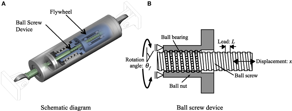
Figure 1. A simple inertial mass damper. (A) Schematic diagram and (B) ball screw device.
The produced inertial force is given by the design variables of the IMD as follows. The rotation angle, θf, of the rod connected to the flywheel is given by
where x denotes the axial displacement of the IMD and L denotes the ball screw lead, which is the linear length that a ball nut moves in one rotation of the ball screw. The inertial torque, Tf, generated by the revolving flywheel is given by
where If denotes the moment of inertia of the flywheel. The axial inertial forces of the IMD, Nf, corresponding to the above torque, Tf, can be expressed as follows:
where
and η is the rotary efficiency of the ball screw. Equation 3 indicates that the produced inertial force is in proportion to the acceleration of the IMD and φd can be regarded as the equivalent inertial mass of the IMD. Equation 4 indicates that a large inertial mass can be created by amplifying If.
The EIMD in this study comprises a ball screw device, a gear, a flywheel, and an electric generator set up in a cylinder, as shown in Figure 2 (Nakamura et al., 2014). A gear is set up between the ball screw and the flywheel that amplifies the rotation of both the flywheel and the rotating shaft of the generator. Rotary motion generates the inertial force and the electromagnetic damping force. A resistor is connected to the terminal of the electric generator, and the terminal resistance is able to adjust the induced electromagnetic damping force.
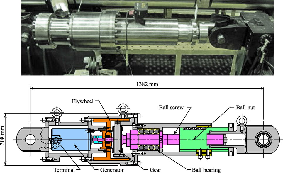
Figure 2. Photograph and schematic of the electromagnetic inertial mass damper.
The formula for the inertial mass and the damping factor of the EIMD were derived in the past studies (Ohtake et al., 2006; Nakamura et al., 2014) as follows. The produced inertial mass of the EIMD in Figure 2, φE, is given by
where α denotes the gear ratio, and Is and Ig denote the moments of inertia of the rotating rod connected to the unamplified side of the gear and of the revolving shaft of the generator, respectively.
The damping coefficient of the EIMD caused by the electric generator for the dissipation of electromagnetic energy is described by the following equation:
where KE and KT represent the electromotive force constant and the torque constant of the generator, respectively, and R and Ra represent the terminal resistance and the internal resistance of the generator, respectively. The damping coefficient, cE, is controlled by the value of R, and is maximized when R is 0, such as in the case of a closed-circuit system, while cE is minimized when R is infinite, such as in the case of an open-circuit system.
Design and Performance of a Full-size EIMD
A full-size EIMD was designed and assembled as shown in Figure 2 (Nakamura et al., 2014). The design parameters of the full-size EIMD are given in Table 1. The produced inertial mass, φE, is estimated at 2.0 × 10⁶ kg, or 2,000 ton using Eq. 5 and is governed by the amplified moment of inertia of the flywheel. The damping coefficient, cE, is estimated using Eq. 6 and is maximized at 3.045 × 10⁶ N⋅s/m for R = 0 Ω.
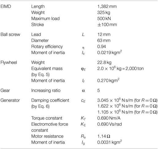
Table 1. Full-size electromagnetic inertial mass damper (EIMD) design parameters.
Figure 3 shows the data for the experimental axial resisting force versus the deformation of the full-size EIMD compared to the theoretical curve. The hysteresis curves in Figure 3 show negative gradients due to the generated inertial mass and develop loops due to the induced electromagnetic damping force. Figure 3 shows that the slope of the experimental hysteresis curve is in good agreement with the theoretical value, and that the theoretical hysteresis curve predicts the experiment curve accurately.
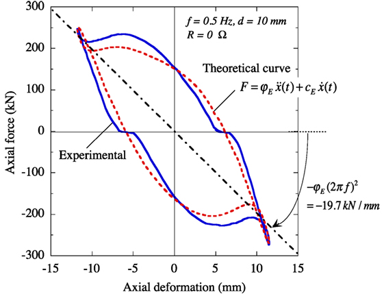
Figure 3. Full-size electromagnetic inertial mass damper resisting force characteristics.
Tuned Electromagnetic Inertial Mass Damper
Configuration of Standard T-IMD
The standard T-IMD comprises an IMD (Figure 1), a spring element connected in series, and a supplemental damper combined in parallel when necessary, and is installed in a structure as shown in Figure 4. The T-IMD functions as a single-degree-of-freedom (SDOF) oscillator, and the spring element plays the role of tuning the natural period of the T-IMD. The supplemental damper such as the viscous fluid damper adds the additional energy dissipation property when necessary.
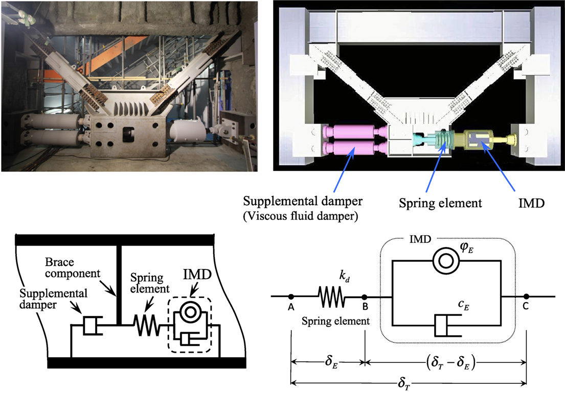
Figure 4. Photograph, configuration and mechanical model of standard tuned inertial mass damper (T-IMD).
Table 2 compares the standard T-IMD and the conventional TMD. Both of these are SDOF oscillators with the natural period that is tuned to the fundamental period of the structure. While the T-IMD is installed interstory-wise and utilizes a large inertial mass produced by the rotating flywheel, the conventional TMD is installed on the top floor of a structure and utilizes a solid concrete or metal block connected with springs, or water filled in tanks (Soong and Dargush, 1997).
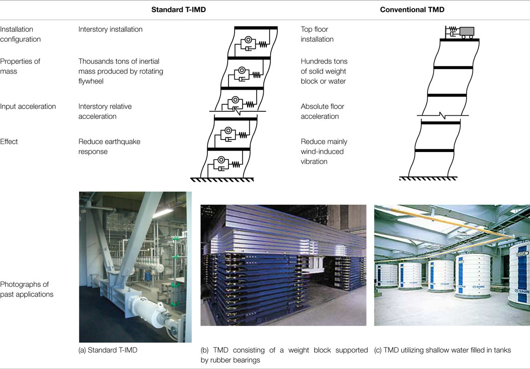
Table 2. Comparison between the standard tuned inertial mass damper (T-IMD) and the conventional tuned mass damper (TMD).
Makeup of T-EIMD
The T-EIMD employs the EIMD (Figure 2) for the IMD in Figure 4. Since the EIMD produces the inertial force and the electromagnetic damping force, the T-EIMD does not require the supplemental damper. A spring element is connected in series with the EIMD, and adjusts the natural period of the T-EIMD.
In the mechanical model of the T-EIMD (Figure 4), kd denotes the stiffness of the spring element for tuning the period, and δT and δE denote the total amplitude of the T-EIMD and the stroke of the EIMD, respectively. δT can be regarded to be the same as the story drift when the brace component can be considered to be sufficiently stiff. Similar to the case of a conventional TMD, the amplitude of the EIMD, δE, can be amplified by the resonance phenomenon by tuning the natural period of the T-EIMD to that of the structure.
The relationship between δT and δE can be obtained as follows. The equilibrium of the axial forces at the point B in Figure 4 leads to
Substituting and into Eq. 7 gives the following equation:
where ω0 denotes the circular frequency of the story sinusoidal oscillation, and
ωE and hE indicate the natural circular frequency and the damping factor of the T-EIMD as an SDOF oscillator, respectively.
When ωE = ω0, i.e., the T-EIMD is synchronized with the story sinusoidal oscillation, Eq. 8 can be expressed as
Equation 10 can be rewritten as
Equation 11 reveals that the stroke of the EIMD, δE, is amplified by 1/2hE and its phase is behind by π/2 against the story drift, δT (Inoue and Ikago, 2012). Substituting Eqs 5 and 6 into Eqs 9b and 11 gives the following equations:
where
For the design parameters in Table 1, Eqs 12a,b can be rewritten as follows.
where TE = 2π/ωE, which is the natural period of the T-EIMD. The damping factor of the T-EIMD is linearly proportional to TE and decreases with the terminal resistance of the generator, R. The amplitude amplification of the T-EIMD for resonant oscillations is inversely proportional to TE and increases with R. It should be noted that these properties are taken from the resonant sinusoidal oscillations and cannot be directly applied for earthquake excitations.
Modal Analysis of Structures with T-EIMDs
Consider a multistory shear building in which T-EIMDs are installed between the floors, as shown in Figure 5. When all of the variables of the structure and of the installed devices can be treated as linear parameters, the mean peak response of the building subjected to a given design response spectrum can be estimated using modal analysis as described in the following.
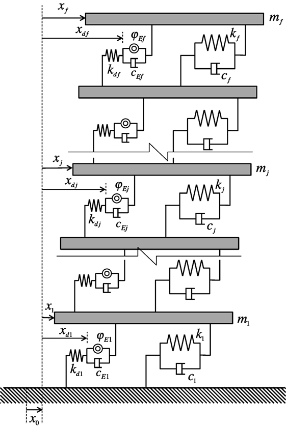
Figure 5. A multistory shear building with tuned electromagnetic inertial mass dampers.
The mass, stiffness, and damping coefficient of the j-th story of the structure are denoted by mj, kj, and cj, respectively. The inertial mass and the damping coefficient of the EIMD in the j-th story are denoted by φEj and cEj, respectively. The stiffness of the spring element connected in series with the IMD in the j-th story is denoted by kdj. The relative horizontal displacement of the j-th floor to the ground is denoted by xj. The displacement of the input earthquake is denoted by x0. The relative displacement of the edge of the spring element in the j-th story to the ground is denoted by xdj.
The equations of motion of an f -story shear building in which T-EIMDs are installed between the floors can be written as follows:
where
It should be noted that the inertial mass matrix, Md, appears only in the response inertial force term on the left side of Eq. 15, but does not appear in the earthquake inertial force term on the right side. This implies that the inertial mass generated by the T-EIMD reduces the apparent input excitation to the structure.
The damping matrix of the structure with T-EIMDs is non-proportional, and the eigenvalue problem is given by Foss’s method (Foss, 1958) as follows:
where E denotes the identity matrix, and
Equation 19 gives f pairs of complex conjugate eigenvalues {λ}, and their corresponding eigenvectors u for damped vibration as listed below.
where and (j = 1, 2, … f) are a pair of complex conjugate eigenvalues. The natural circular frequency, ωj, and the damping factor, hj, of the j-th mode are given by
The mean peak story drifts of the building with T-EIMDs subjected to the given design displacement spectrum can be evaluated by the expanded CQC method (Igusa et al., 1984; Yang et al., 1990) by
where
Re[ ] and Im[ ] denote the real and imaginary parts of a complex number, respectively, and in Eq. 24 are the modal cross-correlation coefficients given as follows (Yang et al., 1990):
where p(r,s) = ωr/ωs.
Performance-Based Placement Design Method of T-EIMDs
A design method for T-EIMDs is presented here such that each peak story drift angle {βj} of an f -story shear building with a given set of {M, C, K} subjected to a specified design earthquake would coincide with the prescribed values ( j = 1, …, f). The prime design target is the story-wise distribution of the inertial mass, {φEj} ( j = 1, …, f) of the installed T-EIMDs, with the other design parameters of the T-EIMDs regarded as dependent variables of {φEj} and the terminal resistance of the generator R. Figure 6 presents a design process for finding {φEj} that is necessary to limit the story drift angles {βj} to the prescribed values . The stiffness of the spring element, {kdj} ( j = 1, …, f), is determined such that the tuning period of the T-EIMD, TE, is equal to the fundamental period, , of the building structure without dampers as follows:
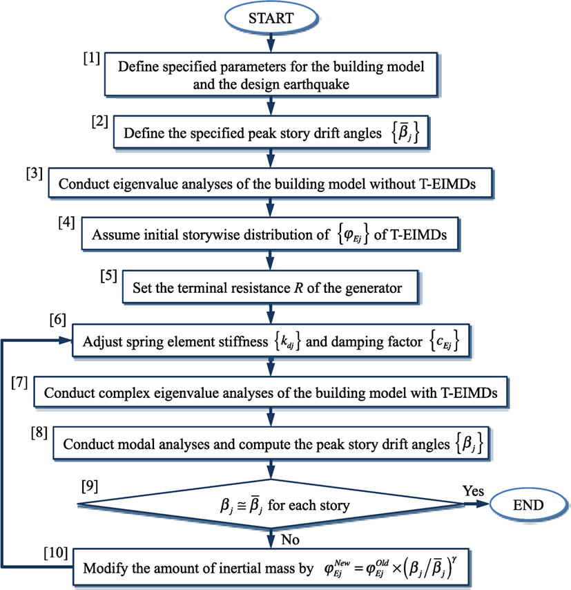
Figure 6. Flow for design of tuned electromagnetic inertial mass dampers (T-EIMDs) for specified story drift angles.
The damping coefficient, {cEj} (j = 1, …, f), of the T-EIMD is regarded as a dependent variable of {φEj} and R, and is adjusted in proportion to {φEj}. In each story, cEj is assumed to be proportional to φEj, and is given by Eq. 6 with the design parameters in Table 1 as
where the terminal resistance of the generator, R, is specified as a common control parameter for the T-EIMDs in the design process. From Eqs 9b and 29, the damping factor, hE, of the installed T-EIMDs is determined by TE and R as follows:
In the design process shown in the 10th step in Figure 6, the inertial mass {φEj} is regulated by the ratio of the evaluated peak story drift angle, {βj}, to the prescribed target value, in each story according to
where γ is the control parameter, specified as 0 < γ ≤ 1. The proposed design procedure utilizes complex eigenvalue analysis, and, therefore, can provide the changes in the natural periods and the damping factors of the building with T-EIMDs.
Design Examples
Multistory Building Models and Design Response Spectrum
Consider 20- and 30-story shear buildings with mass and story stiffness properties given in the previous study (Nakamura et al., 2016). These are based on actual high-rise buildings. The fundamental natural periods of the buildings without dampers, , and their story heights, SL, are as follows:
20-story shear building: , SL = 398 cm,
30-story shear building: , SL = 410 cm.
The damping ratio in the first mode, , is assumed to be 2% and those in the higher modes are assumed to be proportional to the frequency for the two building models.
The story-wise distribution {φEj} of the T-EIMDs is found such that the peak story drift angle {βj} is 1/150 for all stories, i.e., , for the design response spectrum (Level 2) given by the Japan Building Center. The control parameter γ in Eq. 31 in the 10th step in Figure 6 is set to be 0.2.
Story-Wise Placement Progress of Inertial Mass for Specified Peak Story Drift Angle
The extracted progress of the story-wise distribution {φEj} (ton) (j = 1, 2 …, 20) of the T-EIMDs for R = 2 Ω in the 20-story building is shown in Figure 7A, together with the evaluated peak story drift angles in Figure 7B that change according to {φEj}. At first, the story-wise distribution {φEj} of the T-EIMDs is assumed to be uniform for all floors, as shown on the left-hand side of Figure 7A, and the peak story drift angles are evaluated by the expanded CQC method, as shown on the left-hand side of Figure 7B. The inertial mass {φEj} at each floor is modified by the ratio of the evaluated peak story drift angle to the target value using Eq. 31. For the modified inertial mass distribution, the peak story drift angles are repeatedly evaluated and compared to the target value with the modifications repeated until the evaluated peak story drift angles are converged to the target value, as shown on the right-hand sides of Figures 7A,B.
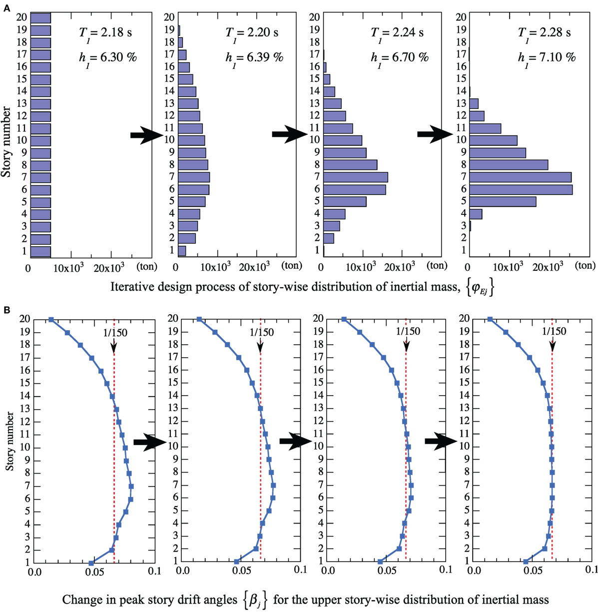
Figure 7. Extracted progress of story-wise distribution of inertial mass and peak story drift angles in 20-story building for R = 2 Ω. (A) Iterative design process of story-wise distribution of inertial mass, {φEj}. (B) Change in peak story drift angles {βj} for the upper story-wise distribution of inertial mass.
Figure 7A also shows the changes in the fundamental natural period, T1, and damping factor, h1, of the building with T-EIMDs computed by the complex eigenvalue analyses during the iterative design process. Installation of T-EIMDs elongates T1 and increases h1, while the tuning period of the installed T-EIMD, TE, is maintained as .
The right-hand side of Figure 7A shows that the final {φEj} exhibits a triangular distribution over the 4th to 13th stories and peaks at the 6th story. The right-hand side of Figure 7B shows that the peak interstory drifts of the upper stories above the 13th story and those of the lower stories below the 4th story fall below the target value of 1/150 without dampers.
Parametric Design of Damping Factor and Tuning Period of T-EIMDs
The damping factor of the installed T-EIMDs, hE, can be controlled by the terminal resistance of the generator, R, and the tuning period, TE, according to Eq. 30, and can be expressed as hE (R, TE). Parametric studies have been carried out here to determine the dependence of the designed inertial mass, {φEj}, on R and TE.
First, {φEj} are determined for R = 0, 1, 2, …, 6 Ω with such that in the 20-story building for the specified design response spectrum. Figure 8 shows the dependence of φE6 and on R, and reveals that both reach a minimum at hE = 0.055 for R = 4 Ω.
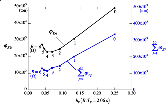
Figure 8. Dependence of necessary inertial mass on the damping factor of tuned electromagnetic inertial mass damper.
Figure 9 shows the variations in T1 and h1 of the 20-story building with the T-EIMDs as a function of R; the results imply that the increase of R hardly affects T1, but largely decreases h1. Figure 10 shows the dependence of the inertial mass, φE6, and the maximum amplitude, δE6, of the sixth story’s T-EIMD on R. While φE6 reaches a minimum at R = 4 Ω as mentioned above for Figure 8, δE6 reaches a maximum for R = 5 Ω and exceeds the allowable stroke of 10 cm of the EIMD given in Table 1. The setting of R = 2 Ω in Figure 7 can restrict δE6 to 10 cm and keep φE6 close to a minimum. Therefore, R can be regarded as a control parameter in terms for the minimization of the installed T-EIMDs with a limited stroke.
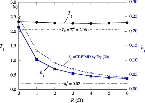
Figure 9. Variation of the fundamental natural period and damping factor with the terminal resistance.
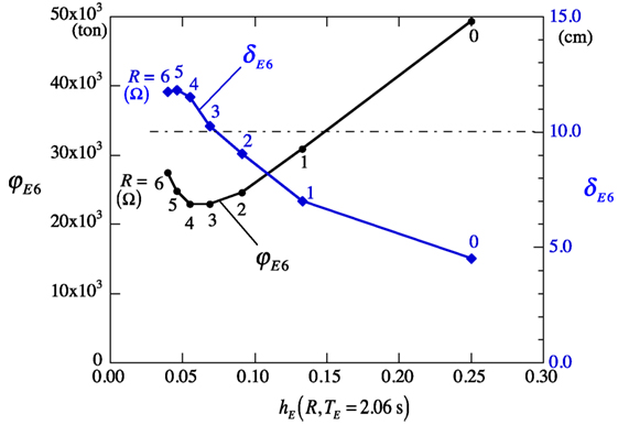
Figure 10. Dependence of inertial mass and maximum amplitude of the sixth story’s tuned electromagnetic inertial mass damper on its damping factor.
Next, {φEj} are determined for the varied TE values with R = 4 Ω such that in the 20-story building. Figure 11 shows the dependence of φE6 and on , implying that both vary with and that the setting of is found to be adequate for the minimization of {φEj}.
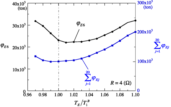
Figure 11. Dependence of necessary inertial mass on the tuned electromagnetic inertial mass damper tuning period.
Necessary Story-Wise Number of T-EIMD Unit for Specified Peak Story Drift Angle
Figure 12 shows the obtained story-wise distribution, {φEj} (ton), and the necessary number of T-EIMD units, {NEj} in the 20- and 30-story buildings, where {NEj} was obtained by dividing the obtained inertial mass by 2,000 ton (= the inertial mass of an EIMD unit in Table 1) and rounding off to a whole number. The stiffness of the spring element, {kdj} (kN/m) and the damping coefficient, {cEj} (kN⋅s/m) of the installed T-EIMD are given by Eqs 28 and 29 as follows:
where , and R = 2 Ω.
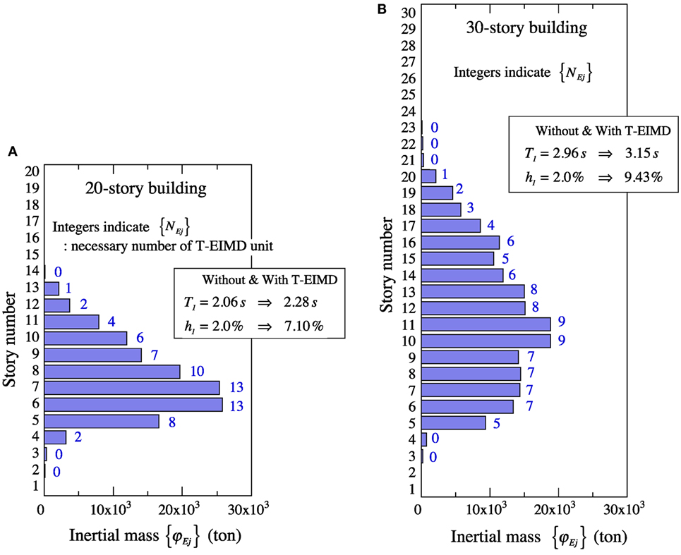
Figure 12. Obtained story-wise distribution of inertial mass and necessary number of T-tuned electromagnetic inertial mass dampers in 20- and 30-story buildings for peak story drift angle of 1/150. (A) 20-story building, and (B) 30-story building.
The proposed placement-design procedure can estimate the degree of the variations in the T1 and h1 of the building installed with the T-EIMDs by complex eigenvalue analyses. The T1 and h1 values of the 20- and 30-story building with and without the T-EIMDs are shown in Figure 12. The required T-EIMDs lengthen T1 to some extent and considerably increase h1 due to their inertial mass and damping coefficient. These variations in T1 and h1 can convey important information regarding the dynamic properties of the building.
Verification by Time–History Earthquake Response Analyses
To demonstrate the adequacy of the proposed design method, the buildings installed with the necessary number of the T-EIMD units were subjected to 10 synthetic earthquake waves generated to be compatible with the given design response spectrum (Nakamura et al., 2016).
Figure 13 shows the story-wise distribution of the mean peak story drift angles estimated by the time–history response analyses of the 20- and 30-story buildings with and without the T-EIMD units. With the exception of the lower and upper floors, for which the installation of a T-EIMD unit is unnecessary, the mean peak story drift angles are found to be limited to the specified value of 1/150 with sufficient accuracy.
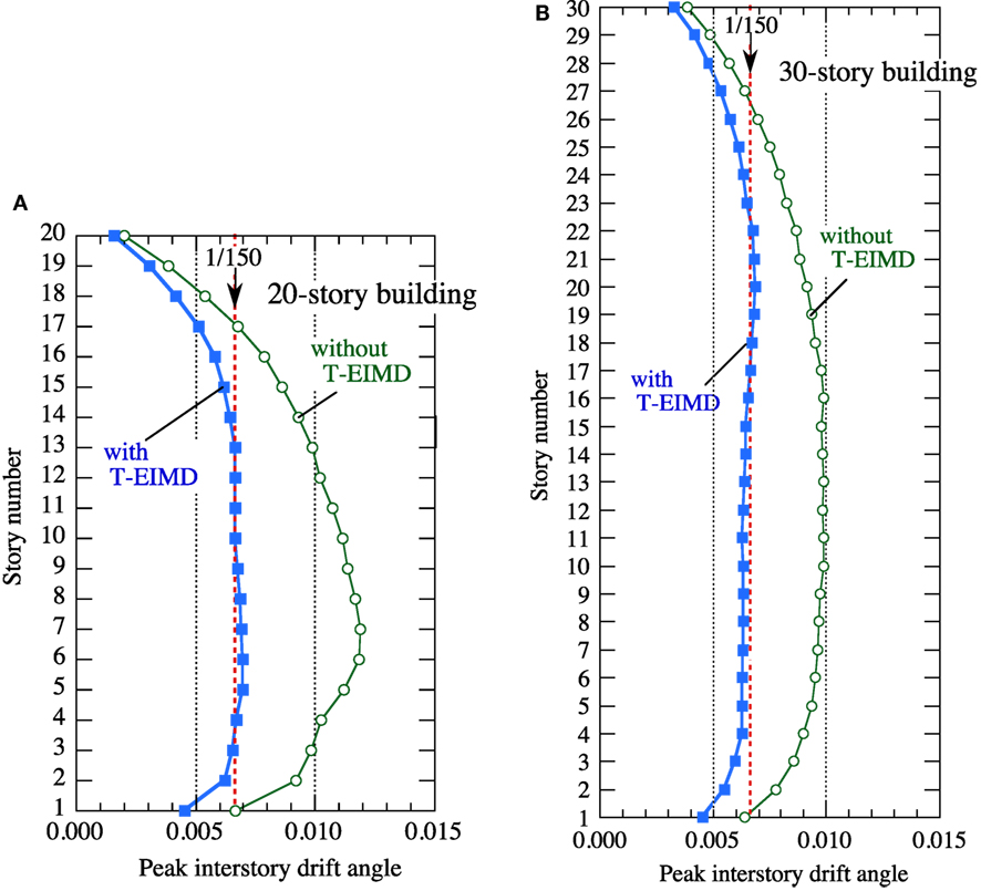
Figure 13. Mean peak story drift angles in buildings without tuned electromagnetic inertial mass dampers (T-EIMDs) and buildings with T-EIMDs designed for maximum story drift angle of 1/150. (A) 20-story building, and (B) 30-story building.
Conclusion
A T-EIMD is a new kind of the TMD that is installed between the adjacent floors of a building and utilizes a large inertial mass and variable damping force. A performance-based design method of T-EIMDs is presented to find the story-wise distribution of T-EIMDs in a multistory building such that each maximum story drift would be restricted to the target value for a specified design earthquake response spectrum. The EIMD studied in this paper is based on a full-size EIMD that was actually designed and assembled for performance testing.
The T-EIMD comprises a ball screw device, a gear, a flywheel, a generator, and a spring element. The T-EIMD is able to produce a large inertial mass by converting the linear oscillation of the rod end into the rotating motion of the flywheel. The spring element connected in series acts to tune the natural period of the T-EIMD to the fundamental natural period of the building and amplifies the amplitude of the T-EIMD. An attached electric generator rotated by the revolving rod is able to develop a variable damping force that can be controlled by the terminal resistance.
The proposed design method utilizes the expanded CQC method to evaluate the maximum story drifts of a multistory building with installed T-EIMDs subjected to a specified design earthquake response spectrum. In the proposed sequential design procedure, the inertial mass of the T-EIMD in each story is regulated by the ratio of the evaluated maximum story drift angle to the target value. Dividing the obtained inertial mass by the inertial mass of an EIMD unit and rounding off the result to a whole number give the necessary number of the T-EIMD units at each story. The stiffness of the spring element of the T-EIMD is determined to meet the period tuning condition, and its damping coefficient is determined by the given design parameters and the terminal resistance.
Design examples of the performance-based placements of the T-EIMDs are shown for two multistory building models. The parametric design studies show that the terminal resistance functions as a control parameter for limiting the T-EIMD’s amplitude and minimizing the installed T-EIMDs, and that the tuning to the fundamental natural period of the building is adequate for the minimization of the installed T-EIMDs. Time–history response analyses are carried out for the buildings installed with the necessary number of T-EIMDs subjected to the design response spectrum-compatible synthetic earthquakes. The results demonstrate the effectiveness and the validity of the proposed performance-based design procedure.
The developed design procedure can be applied not only to the EIMD but also to the standard T-IMD (in Figure 4) that consists of an IMD (in Figure 1), a spring element connected in series, and a supplemental damper combined in parallel. The damping coefficient of the supplemental damper can be regarded as a control parameter similar to the terminal resistance of the T-EIMD. Another merit of the proposed method is that the changes in the fundamental natural period and the damping ratio of the building due to the installed T-EIMDs can be estimated using complex eigenvalue analysis, providing valuable information regarding the dynamic properties of the building.
Author Contributions
YN: development of performance-based placement method of tuned electromagnetic inertial mass dampers and computation of design examples. TH: generation of synthetic earthquake motions and time–history response analyses of design examples.
Conflict of Interest Statement
The authors declare that the research was conducted in the absence of any commercial or financial relationships that could be construed as a potential conflict of interest.
Acknowledgments
An electromagnetic inertial mass damper (EIMD) used in this paper was studied by a joint research project between Akita University, Sanwa Tekki Corporation and Shimizu Corporation (Nakamura et al., 2014). The authors would like to express their appreciation to Dr. Katsuaki Sunakoda, Dr. Kazuhiko Hiramoto, Dr. Taichi Matsuoka, Dr. Kazuo Tamura, and Dr. Akira Fukukita for their collaboration in the study of EIMD. The authors also would like to thank Enago (www.enago.jp) for the English language review.
Funding
The authors did not utilize any funding institutions.
Supplementary Material
The Supplementary Material for this article can be found online at http://journal.frontiersin.org/article/10.3389/fbuil.2017.00026/full#supplementary-material.
Video S1. Action of inertial mass damper.
Video S2. Earthquake response of tuned inertial mass damper.
References
Cimellaro, G. P. (2007). Simultaneous stiffness-damping optimization of structures with respect to acceleration, displacement and base shear. Eng. Struct. 29, 2853–2870. doi: 10.1016/j.engstruct.2007.01.001
Foss, K. A. (1958). Coordinates which uncouples the equations of motion of damped linear dynamic systems. J. Appl. Mech. 25, 361–364.
Furuhashi, T., and Ishimaru, S. (2004). Mode isolation by inertia mass: study on response control by inertia mass no. 1. J. Struct. Construct. Eng. 576, 55–62 (in Japanese). doi:10.3130/aijs.69.55_1
Furuhashi, T., and Ishimaru, S. (2006). Response control of multi-degree system by inertia mass no. 2. J. Struct. Construct. Eng. 601, 83–90 (in Japanese). doi:10.3130/aijs.71.83_2
Garcia, D. L. (2001). A simple method for the design of optimal damper configurations in MDOF structures. Earthq. Spectra 17, 387–398. doi:10.1193/1.1586180
Gluck, N., Reinhorn, A. M., Gluck, J., and Levy, R. (1996). Design of supplemental dampers for control of structures. J. Struct. Eng. 122, 1394–1399. doi:10.1061/(ASCE)0733-9445(1996)122:12(1394)
Igusa, T., Der Kiureghian, A., and Sackman, J. L. (1984). Modal decomposition method for stationary response of non-classically damped systems. Earthq. Eng. Struct. Dyn. 12, 121–136. doi:10.1002/eqe.4290120109
Ikago, K., and Inoue, N. (2013). “Fundamental modes of seismic control multi-story shear building using tuned viscous mass damper: an analytical study on a case in which the secondary mass distribution is proportional to that of primary stiffness,” in Proceedings of 13th World Conference on Seismic Isolation, Energy Dissipation and Active Vibration Control of Structures (Sendai, Japan). Paper 900718.
Ikago, K., Saito, K., and Inoue, N. (2012a). Seismic control of single-degree-of-freedom structure using tuned viscous mass damper. Earthq. Eng. Struct. Dyn. 41, 453–474. doi:10.1002/eqe.1138
Ikago, K., Sugimura, Y., Saito, K., and Inoue, N. (2012b). Modal response characteristics of a multi-degree-of-freedom structure incorporated with tuned viscous mass dampers. J. Asian Architect. Build. Eng. 11, 375–382. doi:10.3130/jaabe.11.375
Ikago, K., Saito, K., Sugimura, Y., and Inoue, N. (2010). “Optimum seismic response control of multiple degree of freedom structures using tuned viscous mass dampers,” in Proceedings of the 10th International Conference on Computational Structures Technology (Valencia, Spain). Paper 164.
Ikago, K., Sugimura, Y., Saito, K., and Inoue, N. (2011a). “Seismic displacement control of multiple-degree-of-freedom structures using tuned viscous mass dampers,” in Proceedings of the 8th International Conference on Structural Dynamics (Leuven, Belgium), 1800–1807. EURODYN 2011.
Ikago, K., Saito, K., and Inoue, N. (2011b). “Optimum multi-modal seismic control design of high-rise buildings using tuned viscous mass dampers,” in Proceedings of the 13th International Conference on Civil, Structural and Environmental Engineering Computing (Chania, Crete, Greece). Paper 170.
Inoue, N., and Ikago, K. (2012). Displacement Control Design of Buildings. Japan: Maruzen (in Japanese).
Isoda, K. (2012). Japan Patent P4968682 (April 13, 2012), P5051590 (August 3, 2012), P5062561 (August 17, 2012).
Isoda, K., Hanzawa, T., and Tamura, K. (2009). A study on response characteristics of a sdof model with rotating inertia mass dampers. J. Struct. Construct. Eng. 642, 1469–1476 (in Japanese). doi:10.3130/aijs.74.1469
Isoda, K., Hanzawa, T., and Tamura, K. (2010). A study on earthquake energy input to the structure with rotating inertial mass dampers. J. Struct. Construct. Eng. 650, 751–759 (in Japanese). doi:10.3130/aijs.75.751
Isoda, K., Hanzawa, T., and Tamura, K. (2013). Basic study on vibration control system by rotating inertial mass dampers concentrated in the lower stories. J. Struct. Construct. Eng. 686, 713–722 (in Japanese). doi:10.3130/aijs.78.713
Kida, H., Watanabe, Y., Nakaminami, S., Tanaka, H., Sugimura, Y., Saito, K., et al. (2011). Full-scale dynamic tests of tuned viscous mass damper with force restriction mechanism and its analytical verification. J. Struct. Construct. Eng. 665, 1271–1280 (in Japanese). doi:10.3130/aijs.76.1271
Lavan, O., and Levy, R. (2005). Optimal design of supplemental viscous dampers for irregular shear-frames in the presence of yielding. Earthq. Eng. Struct. Dyn. 34, 889–907. doi:10.1002/eqe.458
Lavan, O., and Levy, R. (2006). Optimal design of supplemental viscous dampers for linear framed structures. Earthq. Eng. Struct. Dyn. 35, 337–356. doi:10.1002/eqe.524
Liu, W., Tong, M., Wu, Y., and Lee, G. C. (2004). Optimized damping device configuration design of a steel frame structure based on building performance indices. Earthq. Spectra 20, 67–89. doi:10.1193/1.1648334
Liu, W., Tong, M., Wu, Y., and Lee, G. C. (2005). Optimization methodology for damper configuration based on building performance indices. J. Struct. Eng. 131, 1746–1756. doi:10.1061/(ASCE)0733-9445(2005)131:11(1746)
Nakamura, Y., Fukukita, A., Tamura, K., Yamazaki, I., Matsuoka, T., Hiramoto, K., et al. (2014). Seismic response control using electromagnetic inertial mass dampers. Earthq. Eng. Struct. Dyn. 43, 507–527. doi:10.1002/eqe.2355
Nakamura, Y., and Hanzawa, T. (2002). “Performance-based placement design of vibration control dampers,” in Structural Engineers World Congress SEWC2002 (Yokohama, Japan). T2-4-a-1.
Nakamura, Y., Hanzawa, T., and Isoda, K. (2013). “Performance-based placement design of tuned inertial mass dampers,” in Proceedings of 13th World Conference on Seismic Isolation, Energy Dissipation and Active Control of Structures (Sendai, Japan).
Nakamura, Y., Hanzawa, T., Nomura, T., and Takada, T. (2016). Performance-based placement of manufactured viscoelastic dampers for design response spectrum. Front. Built Environ. 2:10. doi:10.3389/fbuil.2016.00010
Ohtake, T., Sunakoda, K., and Matsuoka, T. (2006). “Study on vibration control device using power generator,” in 2006 ASME Pressure Vessels & Piping/ ICPVT-11 Conference (Vancouver, BC, Canada). No.93534.
Park, J.-H., Kim, J., and Min, K.-W. (2004). Optimal design of added viscoelastic dampers and supporting braces. Earthq. Eng. Struct. Dyn. 33, 465–484. doi:10.1002/eqe.359
Ribakov, Y., and Gluck, J. (1999). Optimal design of ADAS damped MDOF structures. Earthq. Spectra 15, 317–330. doi:10.1193/1.1586043
Shijo, T., Ikenaga, M., Ikago, K., and Inoue, N. (2015). Optimum response control of multi-degree-of-freedom seismic control system incorporated with concentratedly arranged tuned viscous mass dampers. J. Struct. Construct. Eng. 80, 1393–1402 (in Japanese). doi:10.3130/aijs.80.1393
Silvestri, S., and Trombetti, T. (2007). Physical and numerical approaches for the optimal insertion of seismic viscous dampers in shear-type structures. J. Earthq. Eng. 11, 787–828. doi:10.1080/13632460601034155
Singh, M. P., and Moreschi, L. M. (2002). Optimal placement of dampers for passive response control. Earthq. Eng. Struct. Dyn. 31, 955–976. doi:10.1002/eqe.132.abs
Soong, T. T., and Dargush, G. F. (1997). Passive Energy Dissipation Systems in Structural Engineering. Chichester: John Wiley & Sons.
Sugimura, Y., Saito, K., Ikago, K., and Inoue, N. (2010). A study on response control of multi-story building structure using tuned viscous mass dampers. J. Struct. Eng. 56B, 153–161 (in Japanese).
Takewaki, I. (1997). Optimal damper placement for minimum transfer functions. Earthq. Eng. Struct. Dyn. 26, 1113–1124. doi:10.1002/(SICI)1096-9845(199711)26:11<1113::AID-EQE696>3.0.CO;2-X
Takewaki, I., Moustafa, A., and Fujjita, K. (2013). “Optimal placement of visco-elastic dampers and supporting members under variable critical excitations,” in Improving the Earthquake Resilience of Buildings, ed. H. Pham (London: Springer), 249–275.
Takewaki, I., Yoshitomi, S., Uetani, K., and Tsuji, M. (1999). Non-monotonic optimal damper placement via steepest direction search. Earthq. Eng. Struct. Dyn. 28, 655–670. doi:10.1002/(SICI)1096-9845(199906)28:6<655::AID-EQE833>
Tamura, K., and Isoda, K. (2009). “Study on a vibration control system with rotary mass devices,” in JSSI 15th Anniversary International Symposium on Seismic Response Controlled Buildings for Sustainable Society (Tokyo).
Tamura, K., Isoda, K., and Nakamura, Y. (2010). “Response characteristics of a structure with a vibration control system using rotating inertial mass,” in 5th World Conference on Structural Control and Monitoring (Tokyo).
Tan, P., Dyke, S. J., Richardson, A., and Abdullah, M. (2005). Integrated device placement and control design in civil structures using genetic algorithms. J. Struct. Eng. 131, 1489–1496. doi:10.1061/(ASCE)0733-9445(2005)131:10(1489)
Tsuji, M., and Nakamura, T. (1996). Optimum viscous dampers for stiffness design of shear buildings. Struct. Des. Tall Build. 5, 217–234. doi:10.1002/(SICI)1099-1794(199609)5:3<217::AID-TAL70>3.0.CO;2-R
Xu, Z.-D., Shen, Y.-P., and Zhao, H.-T. (2003). A synthetic optimization analysis method on structures with viscoelastic dampers. Soil Dyn. Earthq. Eng. 23, 683–689. doi:10.1016/j.soildyn.2003.07.003
Yang, J. N., Sarkani, S., and Long, F. X. (1990). A response spectrum approach for seismic analysis of nonclassically damped structure. Eng. Struct. 12, 173–184. doi:10.1016/0141-0296(90)90004-C
Keywords: inertial mass, ball screw, electromagnetic, variable damping, tuned mass damper, performance-based design, complex eigenvalue analysis, complete quadratic combination method
Citation: Nakamura Y and Hanzawa T (2017) Performance-Based Placement Design of Tuned Electromagnetic Inertial Mass Dampers. Front. Built Environ. 3:26. doi: 10.3389/fbuil.2017.00026
Received: 21 December 2016; Accepted: 30 March 2017;
Published: 24 April 2017
Edited by:
Nikos D. Lagaros, National Technical University of Athens, GreeceReviewed by:
Sameh Samir F. Mehanny, Cairo University, EgyptConstantinos Repapis, Piraeus University of Applied Sciences, Greece
Copyright: © 2017 Nakamura and Hanzawa. This is an open-access article distributed under the terms of the Creative Commons Attribution License (CC BY). The use, distribution or reproduction in other forums is permitted, provided the original author(s) or licensor are credited and that the original publication in this journal is cited, in accordance with accepted academic practice. No use, distribution or reproduction is permitted which does not comply with these terms.
*Correspondence: Yutaka Nakamura, eXV0YWthLm5ha2FtdXJhQHNoaW16LmNvLmpw