 Athanasios Agalianos
 Antonia Psychari
 Michalis F. Vassiliou*
 Bozidar Stojadinovic
 Ioannis Anastasopoulos
- Department of Civil, Environmental and Geomatic Engineering, ETH Zurich, Zurich, Switzerland
Rocking isolation of structures is evolving as an alternative design concept in earthquake engineering. The present paper investigates the seismic performance of an actual overpass bridge of the Attiki Odos motorway (Athens, Greece), employing two different concepts of rocking isolation: (a) rocking of the piers on the foundation (rocking piers); and (b) rocking of the pier and foundation assembly (rocking footings) on the soil. The examined bridge is an asymmetric 5-span system having a continuous deck and founded on surface foundations on a deep clay layer. The seismic performance of the two rocking-isolated bridges is comparatively assessed to the existing bridge, which is conventionally designed according to current seismic design codes. To that end, 3D numerical models of the bridge–foundation–abutment–soil system are developed, and both static pushover and non-linear dynamic time history analyses are performed. For the latter, an ensemble of 20 records (10 ground motions of 2 perpendicular components each) that exceed the design level are selected. The conventional system collapses in 5/10 of the (intentionally severe) examined seismic excitations. The rocking piers design alternative survives in 8/10 of the cases examined, with negligible residual deformations. The safety margins of the rocking footings design concept are even larger, as it survives in all cases examined. Both rocking isolation concepts are proven to offer increased levels of seismic resilience, reducing the probability of collapse and the degree of structural damage. Nevertheless, in the rocking piers design alternative high stress concentrations at the rotation pole (pier base) are developed, indicating the need for a special design of the pier ends. This is not the case for the rocking footings concept, which however is subject to increased residual settlements but no residual rotations.
Introduction
Motivated by the exceptional behavior of tall, slender, and seemingly unstable structures (such as water tanks and tombstones) during the 1960 Chilean Earthquake, Housner (1963) published his seminal paper where he explained the dynamic stability of rocking structures. In the same earthquake, other seemingly more stable structures, such as buildings and bridges, collapsed. Since then, the rocking motion has been extensively studied using conceptual models (Yim et al., 1980; Psycharis and Jennings, 1983; Zhang and Makris, 2001; Dimitrakopoulos and DeJong, 2012; among others) to conclude that large slender structures present remarkable stability against earthquakes. This conclusion is confirmed by the ancient temples in the Mediterranean that have survived multiple earthquakes for more than 2.5 millennia (Stiros, 1996). The most important finding of such conceptual models is that the stability of rocking objects is controlled by both the frequency of the excitation and the size of the rocking structure: ground motions whose spectra are dominated by high frequency content have less overturning potential, while out of two rectangular rigid blocks (Figures 1A,B) with the same aspect ratio, the largest one is more stable. The latter can be easily understood through displacement-based design concepts: a larger block has a larger “displacement capacity” up until it reaches the point of unstable equilibrium.
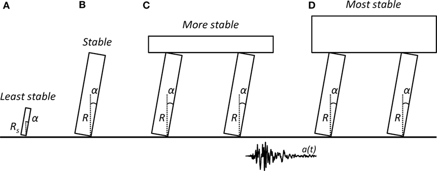
Figure 1. Rigid rocking systems: (A) small block; (B) larger block; (C) rocking frame; and (D) top-heavy rocking frame.
This superior performance of rocking structures has led researchers to propose rocking as an earthquake hazard mitigation technique. According to the concept of “rocking isolation,” instead of trying to fix the structure firmly to the ground, uplifting and rocking is allowed. Such uplifting acts as a mechanical fuse, limiting the forces transmitted to the structure. Rocking isolation aims to increase the safety of a structure against collapse, while simultaneously decreasing the residual displacements. Therefore, rocking isolation enables resilient structures. Additionally, rocking isolation often emerges as a cost-effective approach for the seismic upgrading of existing bridges that do not meet current seismic design code provisions resulting in poor seismic performance, or when the decks of existing bridges need to be widened leading to an increase of the corresponding inertia forces.
Concepts for Rocking Isolation of Bridges
The scope of the present study is to comparatively assess the performance of two rocking isolation concepts for a typical motorway bridge, comparing them to each other, but also to a bridge conventionally designed according to current seismic design codes (Figure 2A). In the field of rocking isolation of bridges, two approaches can be found in the relatively recent literature. The first one refers to rocking of the piers on the foundation (rocking piers, Figure 2B). The piers are not monolithically connected to the foundation; instead, they are designed to uplift and rock under seismic motion, analogous to the response of a rigid block rocking on a rigid base. The second concept promotes rocking of the pier and foundation assembly on the underlying soil (rocking footings, Figure 2C). This behavior is achieved by intentional under-sizing of the foundation to promote uplifting.
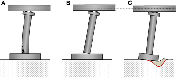
Figure 2. Studied configurations: (A) conventional system; (B) rocking piers; and (C) rocking footings.
The main scope of the present work is to identify the advantages and disadvantages of each design concept (rocking piers, rocking footings and conventional design). To that end, rigorous 3D numerical models of the entire bridge–foundation–abutment–soil system are developed within the ABAQUS finite element (FE) analysis environment (ABAQUS 6.14, 2012) and subjected to static pushover and dynamic non-linear time history analyses with biaxial excitation.
Rocking Piers Concept
Within the rocking piers concept, two approaches have been suggested. A restraining tendon can be used (Mander and Cheng, 1997; Palermo et al., 2004; Chen et al., 2006; Cheng, 2008; Marriott et al., 2009; Makris and Vassiliou, 2014b; Vassiliou and Makris, 2015; Giouvanidis and Dimitrakopoulos, 2017a), or the piers can be allowed to rock without a tendon. The former concept has been recently implemented in practice at the Wigram-Magdala Link Bridge (Liu and Palermo, 2016; Routledge et al., 2016), while a variation of the latter has only been used once, for the South Rangitikei Bridge in New Zealand in the early 1980s (Beck and Skinner, 1973). In this paper, only the systems without restraining tendons are studied.
Makris and Vassiliou (2013, 2014a) used rigid body models to prove that the planar response of the rocking frame shown in Figures 1C,D is equal to the response of an equivalent column with equal aspect ratio, yet larger size. Therefore, the frame is more stable than a column alone, even though its center of mass lies higher. The above finding has been also confirmed experimentally by Drosos and Anastasopoulos (2014) and has been proven for non-symmetric rocking frames (Dimitrakopoulos and Giouvanidis, 2015). The same conclusion holds even when the column flexibility is taken into account (Acikgoz and DeJong, 2012; Vassiliou et al., 2014, 2015, 2017a). Such behavior has been thoroughly examined both analytically and numerically, however, employing predominantly in-plane (2D) models. 2D analysis restrains the response to an impact-like motion, neglecting the phenomenon of wobbling and rolling of the block (i.e., the bridge piers), which might occur during biaxial excitations. Vassiliou et al. (2017b) extended Housner’s model to study the spatial (3D) behavior of a wobbling cylinder, bounded to move above the circumference of its base. They concluded that even though the 2D approximation is not conservative, 3D objects still present remarkable stability when excited dynamically. Rajah et al. (2017) extended the 3D model of Vassiliou et al. (2017b) to study the behavior of a slab supported on wobbling columns. As in the case of the planar rocking frame, the presence of the slab increases the stability of the system, even though it raises its center of mass.
The main disadvantage of such rocking piers systems is that conventional elastic spectrum analysis methods fail to describe their behavior (Makris and Konstantinidis, 2003). Therefore, simplified and easy-to-use methods need to be developed so that practicing engineers are able to design such systems without the need to perform time history analysis.
Construction-wise, special care needs to be taken both to protect the ends of the rocking piers from concrete crushing and to constrain their roll-out motion. However, this problem is already solved (to some extent) by researchers who focused on tendon-restrained concepts: Thonstad et al. (2016) have extended the column via a reduced diameter part that was fitted into a smaller void in the cap beam, while Mashal and Palermo (2017) used external shear keys welded to the steel jackets and the base plates protecting the supporting foundation from crushing. The rocking piers concept is also compatible with prefabrication, as it only requires dry connections and minimizes on-site construction time. It also bypasses the problem of column–foundation rebar intersection, which is a known to be a difficult construction task.
Rocking Footings Concept
The second concept refers to the introduction of a “safety valve” under the foundation blocks of the piers, by deliberately under-sizing them to promote full mobilization of their moment capacity during strong seismic shaking (Figure 2C). In this way, the soil experiences inelastic behavior and the footings are allowed to uplift under seismic excitation (e.g., Mergos and Kawashima, 2005; Gajan and Kutter, 2008; Anastasopoulos et al., 2010; Gelagoti et al., 2012; Antonellis et al., 2015). Depending on the safety factor (FSv) against static (vertical) loading, the mode of intentional foundation failure is either uplifting (for large FSv) or soil yielding (for small FSv) (Anastasopoulos et al., 2012). Especially in the latter case, the improved seismic performance comes at the cost of increased settlement, which needs to be accounted for in design. However, it should be understood that the current seismic design philosophy allows for plastic hinging in the superstructure (namely, at the bottom and at the top of the piers) and this may also result to residual displacements. Therefore, the design question is whether it is the underlying soil or the superstructure elements that should be allowed to deform in the plastic range.
Despite its proven (analytically and experimentally) beneficial seismic performance, such reversal of capacity design (from the superstructure to the soil) is still not allowed by current seismic codes, which only allow limited uplifting of the foundation, prohibiting full mobilization of soil bearing capacity. However, there are a few exceptions of structures that have been designed and constructed employing the concept of rocking footings, such as the Rio–Antirrio bridge in Greece and the Vasco de Gama bridge in Portugal (Pecker, 2003).
The comparative advantage of such a design concept lies in its simplicity and compatibility with the current state of practice. There is no need for special connections, and methods compatible to elastic design spectra have been developed (e.g., Gelagoti et al., 2012). An additional comparative advantage is the increased safety margins against toppling collapse, simply due to the aspect ratio of the rocking element (the footing is wider than the pier, compensating for the slightly increased height). Especially for the case of existing bridges that require retrofit in order to withstand current seismic design loads, or for deck widening purposes, the rocking footings concept might offer the simplest solution: focus on retrofitting the superstructure, taking no action on the existing foundations, allowing them to rock and uplift.
Description of the Bridge Model
An actual overpass bridge (A01-TE23) of the Attiki Odos motorway (Athens, Greece) is used as case study, forming the basis for the developed numerical models. The models are based on the actual bridge, bearing the necessary modifications depending on the analyzed design alternative (conventional, rocking piers, or rocking footings). The original bridge is an asymmetric 5-span system, having a total length of 115.6 m (Figure 3A). The pre-stressed reinforced concrete (RC) deck is 10.4 m wide, continuous with a voided cross section (Figure 3B). System asymmetry refers to both the span length, which varies from 19 to 30 m, and the pier height, which varies from 9 to 10 m. Each RC pier consists of a single, cylindrical 1.8 m diameter column. The bridge is designed according to the provisions of the Greek Seismic (EAK, 2000) and Reinforced Concrete (EKOS, 2000) Codes. C25/30 concrete (fck = 25 MPa) and S500 (fy = 500 MPa) reinforcing steel are used (Figure 3B). The moment–curvature relationships of the piers are derived using cross section analysis with the KSU–RC software (2013) and are shown in Figure 3B. The software uses the Mander model for confined concrete (Mander et al., 1988). Concrete tension strength equal to 1/10 of the compression strength is assumed. The reinforcing steel is modeled as elastoplastic material with hardening. The KSU-RC steel input parameters are (K1, K2, K3, K4) = (4, 25, 40, 1.3), where K1 is the ratio of the strain at start of the strain hardening to the yield strain, K2 is the ratio of strain at ultimate strength to yield strain, K3 is the ratio of ultimate strain to yield strain, and K4 is the ratio of the ultimate strength to the yield strength (KSU-RC, 2013). When the ultimate strength of the cross section is reached (which conventionally defines failure), the moment gradually decreases to a residual value which is kept constant until very large curvatures for numerical reasons.
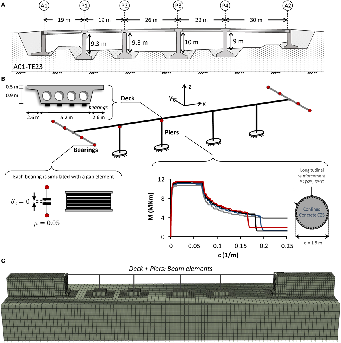
Figure 3. Conventionally designed A01-TE23 overpass bridge of the Attiki Odos motorway: (A) key dimensions; (B) main attributes of the finite element (FE) model of the structural system; and (C) rigorous 3D FE model of the entire bridge–foundation–abutment–soil system.
In the existing bridge, piers P1 and P2 are connected to the deck using a single sliding bearing on top of each pier, allowing for relative pier-deck displacement only in the longitudinal direction. Piers P3 and P4 are monolithically connected to the deck. All piers are founded on square (7 m × 7 m for P1 and P2, 8 m × 8 m for P3 and P4), shallow footings. At each abutment, the deck is sitting on four elastomeric bearings, arrayed in the transverse deck direction. Each abutment consists of a retaining wall (8.3 m tall and 1.8 m thick), connected to two 0.6 m thick sidewalls. Their 8.2 m × 10.4 m abutment foundation is rectangular.
Conventional System
A slightly modified version of the existing A01-TE23 bridge is studied. The relevant numerical model (Figure 3C) is based on the existing bridge and forms the basis for comparison with the rocking-isolated design alternatives. The dimensions of the model are those of the actual bridge, with the exception of pier height, which is simplified to 9 m for all piers. The deck and the piers are modeled with elastic and inelastic beam elements, respectively. The inelastic pier response is simulated using a non-linear model, according to the results of pier cross section moment–curvature analysis. Appropriate gap elements are introduced to model the sliding bearings at the abutments, having a vertical clearance δc = 0 and a friction coefficient μ = 0.05. The footings and the abutments are modeled with elastic brick elements, assuming RC material with E = 30 GPa. Geometric non-linearities (large displacements) are also taken into account in the analysis. According to the results of sensitivity analyses 10 brick elements per side of the foundation are used so that soil–structure interaction is properly modeled.
A 20 m deep homogeneous clay layer of undrained shear strength Su = 150 kPa is considered, also modeled with brick elements. Non-linear (inelastic) soil behavior is modeled with a thoroughly validated kinematic hardening model, with a Von Mises failure criterion and associated flow rule (Anastasopoulos et al., 2011). The evolution law of the model consists of a non-linear kinematic hardening component, which describes the translation of the yield surface in the stress space, and an isotropic hardening component, which defines the size of the yield surface as a function of plastic deformation (Gerolymos and Gazetas, 2005). Calibration of the model parameters requires knowledge of: (a) undrained shear strength Su; (b) the small–strain stiffness (expressed through Go or Vs); and (c) the stiffness degradation (G–γ and ξ–γ curves).
Tensionless interfaces with an appropriate friction coefficient μ = 0.7 are introduced between the subsoil and the footings to model uplifting and sliding, and also between the retaining wall and the embankment to model possible separation of the embankment from the wall. A reinforced earth embankment is considered, applying appropriate kinematic constraints in the transverse direction. For the latter, the same clayey material is considered to avoid further increasing the complexity of the FE model. Nevertheless, the present work focuses on the comparison of the response between the examined configurations. Hence, the material of the embankment is not expected to be of great significance. Appropriate “free-field” boundaries are used at the lateral boundaries of the model, while dashpots are installed at its base to simulate the half-space underneath the soil that is included in the 3D model. The seismic excitation is applied at the base of the model. More details on the development of the rigorous model can be found in the study by Anastasopoulos et al. (2011, 2015).
Rocking Piers Model
The Rocking Piers model (Figure 4A) is based on the model of the conventional system, with the necessary modifications to the piers and the pier–deck and abutment–deck connections in order to ensure purely rocking motion of the piers on top of the corresponding footings. No sliding is allowed for this purpose. As shown in Figure 4C, the piers are modeled with solid elements (instead of beam elements) in order to simulate the rocking interface, where plane sections are not expected to remain plane (Avgenakis and Psycharis, 2017). The pier ends of the actual structure would be protected with steel jackets and no concrete spalling would be expected as it was observed in experimental testing (Thonstad et al., 2016; Mashal and Palermo, 2017). Therefore, elastic concrete material is used to model the piers. Their diameter is increased from 1.8 to 2.0 m to increase the uplifting acceleration and the safety margins against toppling collapse. Sizing the pier diameter does not follow from a formal design procedure, as such a procedure does not exist, but it should only perceived as a trial-and-error approach, the effectiveness of which will be tested de facto. In terms of rocking behavior and with reference to Figure 1, the size parameter of the block (i.e., its semi-diagonal) is R = 4.27 m and its slenderness (i.e., width to height ratio) α = 0.24 rad.
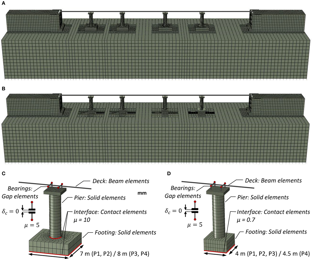
Figure 4. Rigorous 3D finite element model of the entire bridge–foundation–abutment–soil system and key attributes for (A,C) rocking piers and (B,D) rocking footings configurations.
The sliding bearings at the piers and the abutments are also simulated with gap elements, which allow uplifting of the deck and relative pier-deck rotation. Thus, the piers exhibit a purely rocking response with the weight of the deck and the pier being the only restoring force. Four bearings at the top of each pier are considered, placed in a square formation (Figure 4C). A large friction coefficient μ = 10 is assumed for the pier-deck interface, to prohibit sliding of the bearings, allowing only opening or closure of the joint. In reality, a recess or another similar constraint should be implemented to prohibit sliding (Thonstad et al., 2016; Mashal and Palermo, 2017). Special contact elements are introduced between the piers and the footings, allowing uplifting but prohibiting sliding by assuming a large friction coefficient μ = 10 (to ensure purely rocking response of the piers). 32 brick elements are used along the perimeter of each pier. Finally, the interface properties between the footings and the subsoil correspond to an embedded foundation (Figure 4C).
Rocking Footings Model
The Rocking Footings model (Figure 4B) is based on the Rocking Piers model with appropriate modifications. First of all, the piers are monolithically connected to the footings. Moreover, in order to introduce rocking isolation by foundation rocking, the dimensions of the footings are determined so that their moment capacity is smaller than that of the corresponding piers. Thus, full mobilization of the soil bearing capacity and uplifting of the footings will occur before failure of the piers. In the calculation of the moment capacity of a footing against seismic loading, only the horizontal components of the earthquake motion are typically considered. It has been shown that the vertical component has much higher frequency content than the horizontal, and because the two components are asynchronous its effect on moment capacity is minimal (Anastasopoulos et al., 2010). To that end, an “understrength” factor is applied to the footings and their moment capacity is reduced to 1/γRd = 1/1.4 ≈ 0.7 (FSE) of the moment capacity of the relevant piers. Thus, the apparent safety factor against seismic loading (FSE) is lower than 1. Nevertheless, the safety factor against vertical loads (FSv) remains within the range 2.5–3.0. More details on rocking isolation of foundations can be found in the study by Anastasopoulos et al. (2010). A side view of the model is shown in Figure 4B and its key attributes in Figure 4D.
Non-Linear Static Pushover Analysis
Figure 5 plots the results of displacement-controlled non-linear static analysis (pushover analysis) of each model in the longitudinal and the transverse directions. The displacement is applied at the deck level. The vertical axis plots the base shear (of the total structure) and the horizontal one the displacement of the top of Pier P4 relative to the bottom of its footing. The following sections summarize the key observations that can be made.
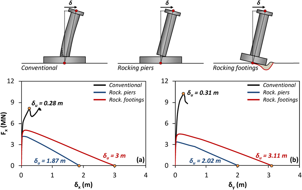
Figure 5. Comparison between the examined systems in terms of static pushover total base shear–drift (F–δ) response of pier P4 in: (A) the longitudinal and (B) the transverse direction.
Conventional Design
For both the longitudinal and the transverse direction, initially the piers behave elastically and the total stiffness of the system is due to their elastic stiffness along with the shear stiffness of the bearings. Subsequently, the piers start yielding at an imposed displacement δ of about 5 cm (in both directions), leading to non-linear behavior of the system. This is the elastic limit that corresponds to a deck drift of less than 1%. An earthquake inducing displacements larger than this yield limit is likely to result in residual displacements, unavoidably reducing the seismic resilience of the bridge.
With increasing horizontal displacement δ, the capacity of the system continues to increase until reaching a maximum, at about 30 cm of displacement (in each direction). Figure 6A plots the deformed geometry at incipient overturning for pushover analysis in the longitudinal direction. At that point, plastic hinges develop at the base of the monolithically connected piers and their strength gradually drops to the residual value. Observe that the resistance of the system in the transverse direction is higher than in the longitudinal. This is because the bearings of P1 and P2 are allowed to slide only in the longitudinal direction (for temperature effects), being fixed in the transverse direction. Therefore, even though in the transverse direction there is no frame action, the mobilization of the two extra piers increases the total resistance of the bridge (compared to the longitudinal direction).
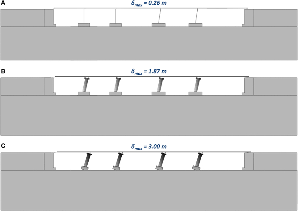
Figure 6. Snapshots of the examined systems at incipient collapse showing contours of total displacement during static pushover analysis in the longitudinal direction for: (A) conventional design; (B) rocking piers; and (C) rocking footings.
Rocking Piers
The pushover curve of Figure 5 reveals the capability of the FE model to capture the pure rocking response of the piers (with sliding being prevented). Initially, the total stiffness of the system is offered by the elastic piers and the bearings at the abutments. The non-linear behavior initiates at displacements of less than 1 cm (in each direction). In contrast to the conventionally designed bridge, this non-linearity is not the result of steel yielding or concrete crushing: it is simply due to the gradual opening of the connection between the piers and the foundation. This non-linearity is, thus, perfectly reversible, provided that the pier ends are adequately protected. Therefore, it may be considered to offer increased levels of seismic resilience.
With increasing applied displacement, the resistance reaches maximum values of 4.2 MN (3.4 MN) at displacements of about 8 cm (5 cm) at the longitudinal (transverse) directions. Subsequently, the resisting force starts to decrease (due to P-Delta effects) and the tangent stiffness of the system becomes negative. Finally, for very large applied displacement of 1.87 m (in the longitudinal) and 2.02 m (in the transverse direction), toppling occurs (no more resistance can be offered). It is worth noting that in the longitudinal direction, the rigid body approximation employed by Makris and Vassiliou (2013) would yield an uplift force equal to 4.62 MN and an overturning displacement of 1.9 m (taking into account that the forces between the deck and the piers are transferred though the bearings, that are placed 10 cm from the perimeter). The error in the force is on the order of 10% and in the displacement on the order of 3%. In the sense of displacement–based design, the “displacement capacity” of the bridge is 1.87 and 2.02 m in the longitudinal and transverse direction, respectively. In stark contrast to conventional design, this failure displacement does not correspond to material failure (provided that the ends of the piers are protected) but to overturning instability.
Figure 6B plots the deformed geometry at incipient overturning for pushover analysis in the longitudinal direction. Contours of total displacement in the longitudinal direction are superimposed. As it can be seen, most of the displacement of 1.87 m is taken by rigid body rotation of the piers. The deformation of the piers, as well as the displacement of the footings, has only a very minor contribution to the total displacement.
An interesting observation is that the piers experience displacement not only in the direction of the imposed displacement but also in the orthogonal direction. More specifically, when the applied displacement in the longitudinal direction exceeds 1.5 m, all piers are also subjected to lateral displacement. The latter proportionally increases (after the first 1.5 m) until reaching a maximum value of about 4 cm, which corresponds to about 2% of the applied displacement. When the pushover displacement is applied in the transverse direction, only pier P1 exhibits rotation around its vertical axis. The aforementioned observation is attributed to the 3D nature of the rocking problem and the phenomenon of wobbling and rolling of the piers (blocks), which might occur during biaxial excitation: small model asymmetries (in this case related with the FE mesh) are enough to cause deformation outside the plane in which displacements are applied. This has been proven theoretically by Stefanou et al. (2011), observed experimentally by Srinivasan and Ruina (2008) and Makris et al. (2015), and confirmed by the numerical results of Vassiliou et al. (2017b).
The role of the abutments is crucial in the redistribution of the vertical load among the four piers. As shown in Figure 7A, in the longitudinal direction, as the piers rotate they tend to lift the deck upward causing a decrease in the abutment vertical reaction forces. For a displacement of 19 cm, the deck detaches from Abutment A1 and the left span of the bridge acts as a cantilever. Most of the reaction of the abutment is then taken by Pier P1 and therefore the axial force in Pier P1 increases. The deck acts as a lever, leading to a decrease of the axial load of Pier P2. The same phenomenon is observed for Abutment A2 and Piers P4 and P3, albeit a larger deformation is needed for complete detachment because the right span of the bridge is longer, thus more flexible. As it will discussed in a later section, this uplift increases the deck design moments above the piers.
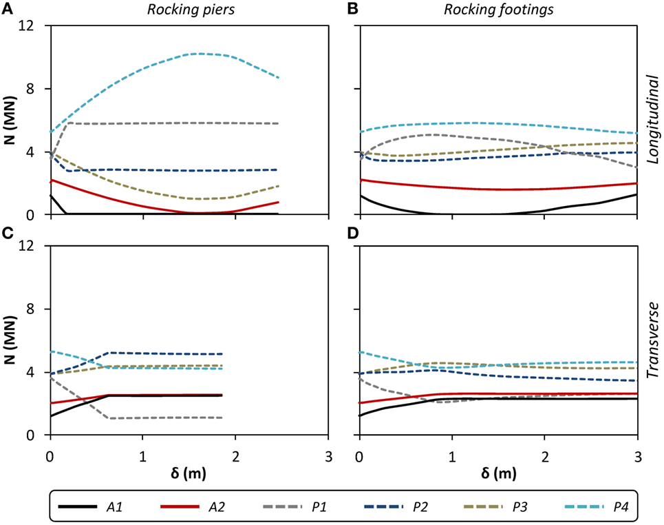
Figure 7. Comparison between the rocking systems in terms of abutment vertical reactions and pier axial loads vs pier drift (N–δ) response during static pushover analysis in each direction for (A,C) rocking piers and (B,D) rocking footings.
In the transverse direction (Figure 7C), the situation reverses: the rotation of the bridge around its longitudinal axis tends to move one side of the deck downward. This increases the reaction of the abutment while the edge piers are unloaded.
Rocking Footings
The pushover response of the rocking footings design alternative is also plotted in Figure 5. Similar to the rocking piers design alternative, the non-linear behavior of the rocking footing model starts at displacements of less than 1 cm for both directions. Subsequently, the gradual uplift of the foundation commences and the resistance increases to a value of 5.1 MN (4.5 MN) at the longitudinal (transverse) direction. The displacement at maximum resistance is in both cases 17 cm. The structure becomes unstable (i.e., negative restoring force) for a displacement equal to 3 m in the longitudinal direction and 3.11 m in the transverse direction, offering increased safety against toppling collapse.
Regarding the rocking mechanism, as the applied displacement increases, the footings start uplifting and rotating. With increasing rotation, the foundation bearing capacity is fully mobilized, and the soil yields due to the developing stress concentrations. The latter unavoidably leads to increased residual deformation and settlement of the footings. This is in accordance with the experimental studies performed by Anastasopoulos et al. (2012), where it was shown that structures with relatively low safety factor against vertical loads (FSv ≤ 2) rock via yielding the soil underneath, while structures with relatively large safety factor against vertical loads (FSv ≥ 10) rock via uplifting.
Figure 6C plots the deformed geometry at incipient overturning for the pushover analysis in the longitudinal direction. Contours of total displacement in the longitudinal direction are superimposed. As in the rocking piers model, most of the displacement in the rocking footings is taken by rigid body rotation of the piers—this time rotating together with the foundations. However, the soil now experiences inelastic behavior, and, as it will be shown later on, this results to residual settlements. Figure 7 shows that axial force redistribution phenomena similar to the rocking piers model take place. The redistribution mainly concerns the reaction force of abutment A1 and pier P1.
Non-Linear Dynamic Time History Analysis
To shed more light in the seismic performance of the three design alternatives, a series of non-linear dynamic time history analyses is performed. An ensemble of 20 historic earthquake records (10 ground motions of 2 perpendicular components each) is used as seismic excitation. The latter covers a range of seismic excitations from strong (e.g., Lefkada-2003) to very strong intensity, characterized by forward-rupture directivity effects, large number of significant cycles, and/or fling step effects (e.g., Takatori, JMA, TCU052). Figure 8 shows the selected records along with their elastic spectra and the design spectrum of the A01-TE23 bridge. It can be seen that all of the selected records exceed the conventional bridge design spectrum, in many cases quite significantly. It is well known that ground motion intensity measures (IMs) developed for elastic structures as well as elastic spectra cannot be used to determine the response of rocking structures (Makris and Konstantinidis, 2003). Even for yielding structures the usefulness of elastic spectra has been also questioned (Makris and Black, 2004; Makris and Psychogios, 2006). Therefore, the elastic spectra should only be perceived as an indication of the destructiveness of the ground motions used in this study.
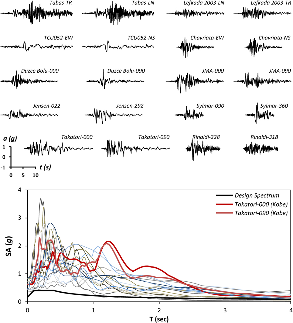
Figure 8. Real earthquake records used for the analysis of the three examined bridge systems, along with their elastic spectra and the design spectrum of the investigated bridge. The selected ensemble of 20 records (10 ground motions of 2 perpendicular components each) covers a range of seismic excitations from strong intensity (e.g., Lefkada-2003), to very strong accelerograms characterized by forward-rupture directivity effects, large number of significant cycles, and/or flingstep effects (e.g., Takatori, JMA, TCU052).
Initially, the response of the three systems is compared using the devastating Takatori record from the 1995 Kobe earthquake as an illustrative example. The selected record constitutes one of the most demanding seismic motions ever recorded, with PGA = 0.70 g, PGV = 169 cm/s bearing the mark of forward-rupture directivity. The pulse duration is roughly 0.7 s and the peak ground acceleration of the pulse is 0.6 g. The Takatori ground motion records are rotated such that the Takatori#000 component lies in the longitudinal direction of the bridge. This comparison aims at assessing the resilience of the three bridge design alternatives subjected to a very severe seismic excitation, by far exceeding the conventional bridge design spectrum.
Conventional Design
Figures 9 and 10 plot the time history response of the pier drifts for the Takatori ground motions. The total drift (between the bottom and the top of the piers) is depicted in Figure 9 for all piers in the longitudinal and in the transverse direction, as well as their vector sum. Figure 10 analyzes the drift to its two components: the flexural and the one originating from rigid body rotation. As shown in Figure 9 (left column), piers P3 and P4 move in phase and no rotation of the deck around the vertical axis occurs. It is reminded that piers P1 and P2 are not monolithically connected to the deck. The maximum displacement at the top of P4 in the longitudinal direction is 69 cm, while the corresponding displacement capacity (as given by the pushover curve) is only 28 cm. In the transverse direction, the maximum displacement reaches 46 cm, also substantially exceeding the capacity (31 cm). Evidently, such seismic excitation not only leads to yielding of the piers (causing potentially non-reparable damage), but also applies such displacements that the columns might lose their vertical bearing capacity. It should be re-iterated that the interaction of the bending strength in the two directions was disregarded. Had it been taken into account, the results would have indicated even larger displacements and even more severe damage.
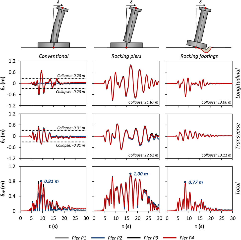
Figure 9. Comparison of the three design alternatives in terms of pier drift at each direction and total pier drift time histories δ(t) for all four piers of the bridge indicatively for Takatori records.
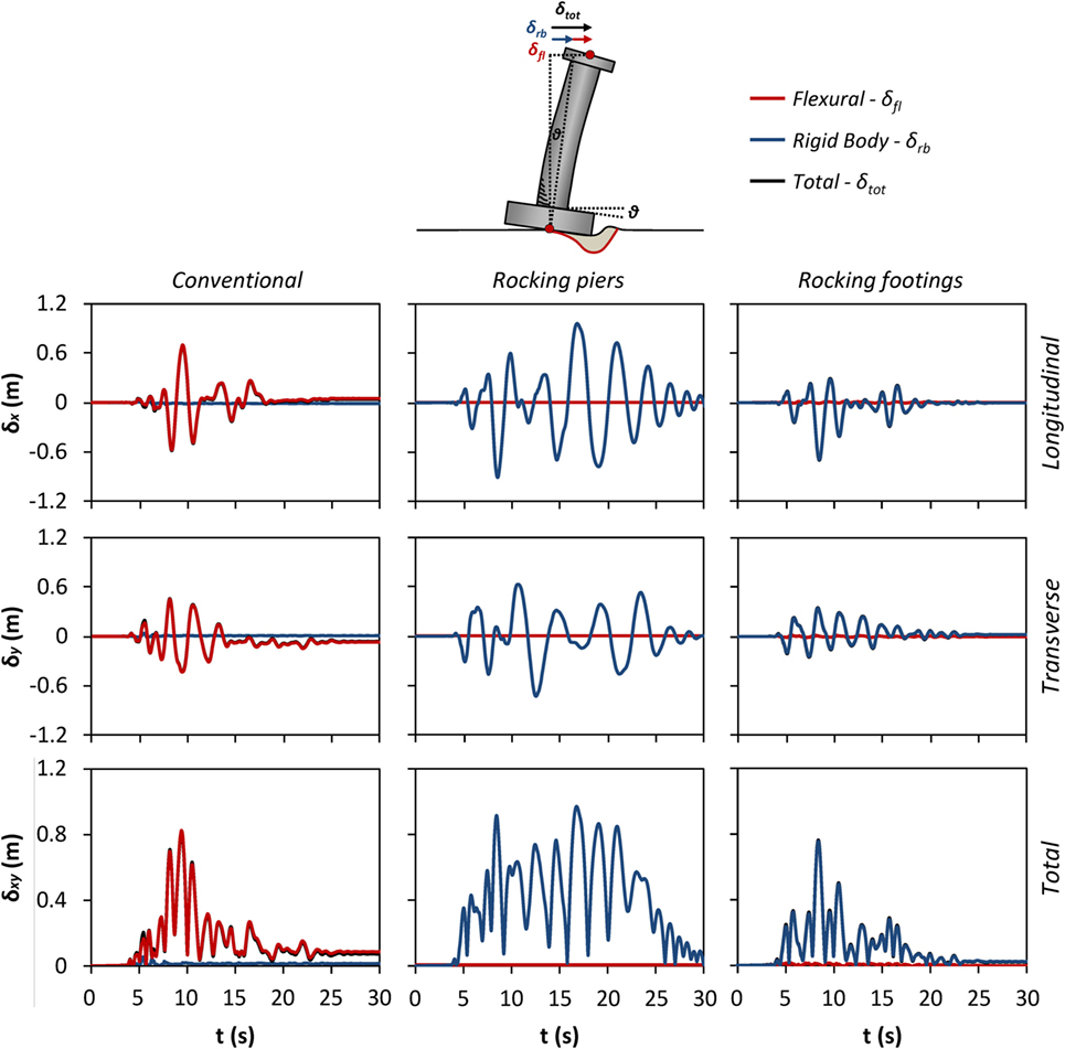
Figure 10. Comparison of the three design alternatives in terms of flexural—rigid body pier drift at each direction, and total pier drift time histories δ(t) indicatively for pier P4 for the Takatori record.
In order to further evaluate the seismic performance of the bridge, two additional very commonly used damage indices are also employed: (a) the ratio of the displacement demand over the displacement capacity (δd/δc) and (b) the drift ratio (δr), which is the displacement at the top of the pier (relative to the bottom of the pier) divided by its height. For the Takatori biaxial excitation, δd/δc reaches a maximum value of 2.5 for pier P4, which corresponds to collapse. The maximum drift ratio of Pier P4 is 7.7%. With reference to conventional bridge column drift response limit states (Priestley et al., 1996), a drift ratio δr > 3% corresponds to probable collapse. The damage and possible collapse is due to the concentration of all the displacement to the “flexural” mode and the failure to mobilize any rigid body mode, as Figure 10 (left column) indicates.
Figure 11 plots the time histories of the bending moments in the two directions at the base of pier P4. The left column refers to the conventionally designed system. The bending strength is reached in both directions, the ultimate curvature is exceeded and then the moment time history can only reach maxima equal to the residual moment strength. The lack of interaction of the bending strength along the two directions is clearly seen, as the vector sum of the maximum moment reaches . This is a limitation of the model. However, since it improves the performance of the conventional system, it further strengthens the key conclusion of the paper regarding the advantageous performance of the rocking systems.
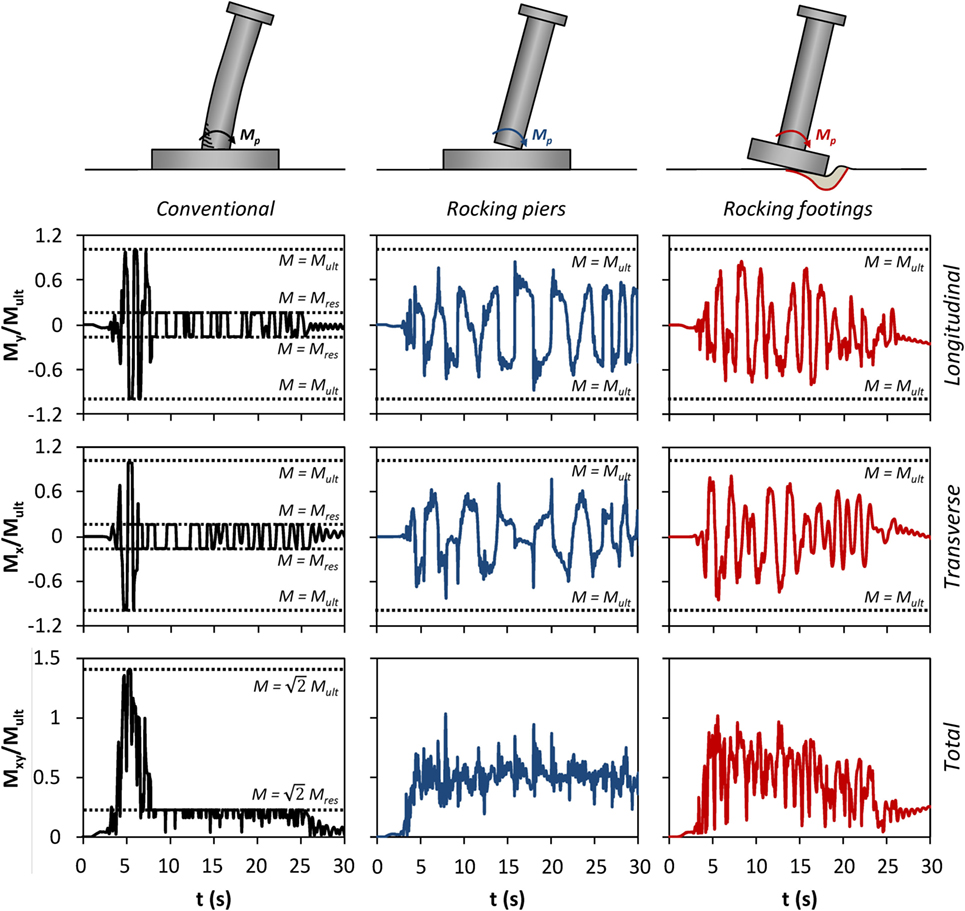
Figure 11. Comparison of the three design alternatives in terms of normalized moment at each direction and total moment to moment capacity time histories M/Mult, indicatively for pier P4 for the Takatori record.
Figure 12 depicts the hysteretic loops of pier P4 in terms of moment–rotation (M–θ) response at each direction. Both (a) the rotation of the plastic hinge vs the moment on the top of the foundation (red) and (b) the rotation of the foundation vs the moment reaction at its bottom (black) are plotted. The area of the loops shows the energy dissipated by each mechanism (RC or soil plastification). The left column refers to the conventional system and it shows that the RC plastic hinge deforms to the point that it reaches its residual strength. This deformation, according to the concrete and steel strain limits prescribed by RC codes, corresponds to failure, either due to unacceptable residual deformations or due to lack of vertical bearing capacity. Unexpectedly, there is some minor plastic deformation of the soil (even though the code philosophy should have guaranteed an elastic soil response).
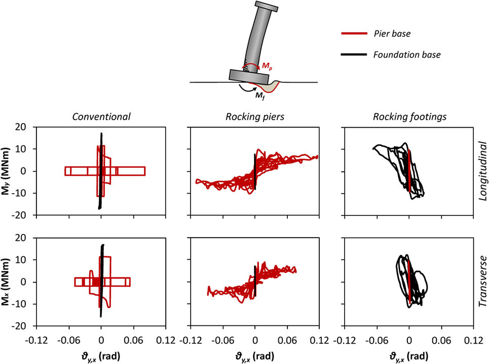
Figure 12. Comparison of the three design alternatives in terms of moment–rotation (M–θ) response at each direction indicatively for pier P4 of the bridge for the Takatori record.
Figure 13 plots the foundation settlement-rotation (w–θ) curves for pier P4. The curves are more useful for the Rocking Footings model described in a later section, but in the case of the conventional system one can observe that there is a residual vertical deformation of 1 cm and no residual rotation.
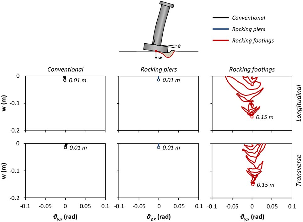
Figure 13. Comparison of the three design alternatives in terms of settlement–rotation (w–θ) response at each direction, indicatively for pier P4 of the bridge for the Takatori record.
Rocking Piers
In contrast to the conventionally design bridge, the rocking piers design alternative survives the Takatori ground motion, avoiding collapse without any structural damage. Figure 9 (middle column) shows that all piers move in phase and that there is (again) essentially no rotation of the bridge around the pier vertical axis. The maximum total (i.e., vector sum) horizontal drift of the piers reaches about 1 m. The latter is significantly smaller than the overturning horizontal drift capacity of the piers (1.87 m): the rocking columns bridge has a large safety margin against toppling collapse.
It is also worth noting that even though the piers are not connected to the foundation, the maximum displacement for the Takatori case is only 23% larger than that of the conventional system. This observation confirms the conclusion by Makris and Vassiliou (2014b) and Vassiliou and Makris (2015) that the presence of reinforcement or restraining tendons has marginal effect on the maximum deformations of large rocking structures. Moreover, it contradicts the widely established belief that increased displacements are always a price that needs to be paid for decreased design loads. Note that the conventionally designed system would likely start collapsing at horizontal displacements larger than 30 cm, when the ductility capacity of the piers is consumed. The analysis assumes a non-zero residual value of moment capacity of the piers (see Figure 3C). The loss of vertical load capacity of the piers is not accounted for, and this suggests that the maximum drift of the conventional system would be much larger in reality (collapse implies that δ → ∞).
Figure 10 shows that there is essentially zero flexural deformation in the piers, and that all of the displacement is taken by rigid body rotation of the piers. The total drift plot (center column, bottom) also shows that there is only one impact (at t = 15.5 s when δxy = 0). From the same plot, one can deduce that the size of the gap between the column and the foundation does fluctuate, but generally it does not become zero, indicating that the column sustains a wobbling motion (i.e., rolling on the perimeter of its base). The change of pivot point is sometimes fast, but it is only scarcely instantaneous, as first observed by Srinivasan and Ruina (2008) and confirmed by Vassiliou et al. (2017b). Figure 11 shows that 3D wobbling motion avoids the very large spikes in the moment time history that planar rocking structures experience (Oliveto et al., 2003; Acikgoz and DeJong, 2012; Truniger et al., 2015; Vassiliou et al., 2015; Giouvanidis and Dimitrakopoulos, 2017b). Spikes do occur, at every fast (but not instantaneous) change of pivot point, but their magnitude is clearly smaller than the ones observed in planar motion and are always smaller than the moment strength of the pier (even when they are vectorially added), as shown in Figure 11. The oscillations after the spike are attributed to the oscillation of the pier itself due to the impact. In any case, in the rocking piers model, the bending moment results should only be perceived as an indication and cannot be used for flexural design, because in the contact area between the piers and the footing, plane sections of the piers do not remain plain, there is a discontinuity of the structure and ordinary RC cross section analysis (which is based on an equivalent continuous beam and only implicitly takes cracking into account) is not expected to yield trustworthy results. Essentially, the problem becomes a question of designing the detailing to protect the pier ends, a task that has been addressed by Thonstad et al. (2016) and Mashal and Palermo (2017).
The smoothing of the motion due to wobbling could be potentially beneficial for reducing the stresses in the structure, but it results in reduced energy dissipation. The moment rotation loops of Figure 12 have a clearly smaller area, indicating less impact damping in the superstructure. The superstructure behaves elastically (given that, for example, steel jackets are used to protect the column ends from spalling) and the observed minimal damping is only due to the contact element forces. The reduced foundation moments result in quasi-elastic behavior of the soil and negligible residual deformation and energy damping. This is an indication that a smaller foundation could have been used, as the maximum foundation moment does not exceed 8.2 MNm, while for the conventional case it is 17.3 MNm. In soft soils, the reduction of the foundation design moment could result in avoiding costly pile foundations.
The detachment of the deck from the abutments causes an increase in the deck moments compared to the conventional system from 22.3 to 27.0 MNm and from −17.6 to −24.5 MNm. A possible solution (not examined in detail in this paper) could be the use of sliding concave bearings at the abutments, so that they follow the up-and-down motion of the deck.
Rocking Footings
Similar to the rocking piers design alternative, collapse is easily avoided in the rocking footings bridge, with the maximum column drift reaching 0.77 m (Figure 9), i.e., roughly four times smaller than the pier toppling capacity (3 m). The piers move in phase and no rotation of the deck around the vertical pier axis is observed. Figure 10 shows that the major component of the drift is the rocking one, albeit there is some minor contribution from flexure. Unlike the rocking piers model, the total displacement, δxy, does become zero: there is limited wobbling (i.e., limited rolling on the perimeter of the foundation). Unlike the almost pointwise contact of the rocking piers model, the larger contact area between the foundation and the soil does not allow for continuous rolling on the foundation perimeter. However, the soil deformability limits the harshness of the rocking impacts, and the bending moment time history (Figure 11, right) does not have the spikes observed in the rocking pier model. The total bending moments at the base of pier P4 (Mtot) never exceed its corresponding moment capacity (Mult).
The moment rotation loops (Figure 12, right column) show that most of the energy is dissipated through soil plastification, while the piers behave elastically. It is notable that the loops do not deteriorate significantly, even after the large rotations (larger than 0.06 rad) and the considerable amount of cycles that the Takatori record induces. This indicates that the inelastic behavior of soil is superior to the plastic behavior of RC, the latter being a composite of an inherently brittle and an inherently ductile material, that has been pushed to its deformation limits.
Figure 13 (right column) reveals that the inelastic behavior of soil results in accumulation of settlements. It is observed that during the first strong motion cycles of the excitation, the footings are subjected to significant rotations, which are subsequently reduced, while the settlement increases. The residual rotation is negligible in all cases, but the settlement reaches 15 cm.
In the rocking footings solution, the detachment of the deck from the abutments increases the design negative moment from −17.6 to −21.4 MNm. However, the design positive moment is decreased from 22.3 to 18.5 MNm.
Summary Comparison for 10 Ground Motions
Figure 14 collectively plots the results for all 10 ground motions. The maximum displacement δxy (along any direction) is plotted vs the PGV of the ground motion. The optimal choice of an earthquake ground motion IM for rocking systems is an open research subject (Gelagoti et al., 2012; Acikgoz and DeJong, 2014; Dimitrakopoulos and Paraskeva, 2015; Kavvadias et al., 2017; Petrone et al., 2017). The selection of an optimal IM does not fall within the scope of this paper, and PGV is used indicatively without further discussion.
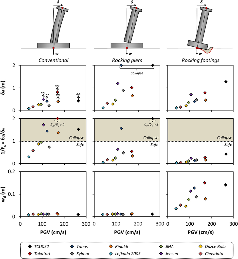
Figure 14. Summary of the response of the three examined systems in terms of maximum drift δd, displacement demand over displacement capacity δd/δu, and maximum settlement wd with respect to the peak ground velocity PGV for the selected ensemble of 20 records (10 ground motions of two perpendicular components each).
For the conventional and the rocking piers system, it is expected that failure along any direction would occur at a displacement roughly equal to the ultimate longitudinal and transverse direction displacement, because the pier displacement failure surface is circular. Therefore, the ultimate displacement (i.e., the one that corresponds to pier failure) is taken equal to 0.28 and 1.87 m, respectively, in any direction. Note that the FE model of the conventional system is non-conservative, because the interaction of moments is neglected. The rocking footings model fails due to overturning around a square foundation. It is therefore expected to have a slightly different displacement capacity along the foundation diagonal, but this is neglected in the discussion presented herein (not in the analyses) and the ultimate displacement capacity is taken equal to 3 m in any direction.
Figure 14 shows that in 5/10 cases (of intentionally selected extremely severe seismic excitations), the conventional bridge collapses. In stark contrast, both rocking design alternatives exhibit remarkable stability. The rocking piers system overturns in only 2/10 ground motions and the rocking footings survives all of them with a maximum drift not exceeding 1/3 of its ultimate capacity. Moreover, Figure 14 shows that the rocking footings system experiences only slightly larger maximum drifts (the median increase is 27%) than the conventional system (even though the former has a much lower strength). The rocking piers system experiences larger displacements than the conventional one (the median increase is 68%). For the calculation of these median values, only the analyses for which the conventional system did not fail are considered (5/10).
The price to pay for the superior stability and reduced displacements of the rocking footings system is the increased settlement of the footings (Figure 14, bottom row), which is clearly larger than the negligible settlement of the conventional and the rocking piers system.
Discussion and Conclusion
The present paper used an actual motorway overpass bridge to comparatively assess the seismic performance of three different design alternatives: one conventional and two based on rocking. For this purpose, 3D numerical models of the entire bridge–foundation–abutment–soil system were developed, and both static pushover and biaxial excitation non-linear dynamic time history analyses were performed. For the latter, 10 very strong earthquake records were used to examine the performance of the three systems subjected to excitations that significantly exceed the design limits.
The conventional, rocking piers, and rocking footings system have displacement capacities on the order of 0.30, 1.90, and 3 m.
For the selected pier and foundation dimensions, the conventional system collapses in half of the examined seismic excitations. Even for design-level earthquakes, for which failure should be avoided, the plastic design concepts on which the conventional design is based lead to non-negligible residual displacements, possibly rendering the bridge non-repairable (something that is acceptable by the current plastic design philosophy). However, this is something that may not have been fully realized by the society, when plastic design methods were adopted in the 1970s (even though there were practicing engineers that were criticizing it since the beginning of its application, as for example, Raptis, 1981). After the 2011–2012 Christchurch earthquake sequence, where only a small percentage of buildings collapsed, but an excessively large portion of the building stock needed to be demolished, there is a societal call for resilient structures. As demonstrated by the results presented in this paper, the conventional design alternative cannot offer the required levels of resilience.
The rocking piers design alternative avoids toppling collapse in 80% of the (intentionally very severe) seismic excitations examined, even without prestressing tendons or extra damping. A design with wider piers or wider pier ends would survive all of them. The residual deformations are negligible, and therefore the structure is resilient and ready-to-use even after severe earthquakes. However, the maximum displacements are larger than the ones of the conventional system (the median increase is 68%). The system requires special protection of the pier ends (e.g., steel jackets) and a restrain to prevent the piers from rolling out of their position. Such jackets have already been used and tested on models with prestressing tendons (for which the contact stresses are expected to be larger), but to the best of the authors’ knowledge a design method is yet to be developed. Furthermore, a special design of the bearings at the pier-deck connection is necessary, so that the rotation of the piers is not constrained. Moreover, the rocking piers system cannot be designed with some simplified, equivalent elastic method and non-linear time history analyses need to be performed. Given that the definition of IMs for rocking structures is an open research subject, there is no consensus on how ground motions should be selected and scaled. Therefore, more research is needed in the direction of understanding rocking dynamics and developing simplified and novel design tools that would allow engineers to rationally design such systems.
The rocking footings solution avoids toppling collapse in all cases examined, clearly offering the largest margins of safety. The residual rotations are practically equal to zero and no residual tilting of the structure is observed in all cases examined. The median increase of maximum displacements (compared to the conventional system) is only 27%. However, the mobilization of foundation bearing capacity unavoidably leads to increased residual settlement, which is the price to pay for such advantageous performance. Compared to the rocking piers solution, it does not require any special construction detailing, and hence it is more straightforward for contractors to construct. Compared to the rocking piers solution, where stress concentrations at the pier-footing contact areas are expected to develop and where potential impacts are more severe, the soil acts as a pillow offering additional damping and limiting the effects of these detrimental phenomena. Moreover, a simplified design method has been outlined by Gelagoti et al. (2012). The rocking footings approach can also be used for the seismic retrofit of existing bridges that were built according to obsolete seismic codes. In such cases, the retrofit could focus on the superstructure, keeping the existing foundation as is, avoiding expensive pilings. By relaxing the allowable uplift criterion for the foundation, the rocking footing design can be introduced in the retrofit, offering the extra benefit of acting as a safety valve, limiting the forces transmitted to the superstructure.
Both rocking systems result in significantly smaller foundation design moment that could result in avoiding costly pile foundations.
Author Contributions
All authors contributed according to their role in their research groups.
Conflict of Interest Statement
The authors declare that the research was conducted in the absence of any commercial or financial relationships that could be construed as a potential conflict of interest.
Funding
Partial support for this work has been provided to MV and BS by the Swiss National Science Foundation under award number 153240.
References
ABAQUS 6.14. (2012). Standard User’s Manual. Providence, RI: Dassault Systèmes Simulia Corp., ETH Zürich.
Acikgoz, S., and DeJong, M. J. (2012). The interaction of elasticity and rocking in flexible structures allowed to uplift. Earthq. Eng. Struct. Dyn. 41, 2177–2194. doi:10.1002/eqe.2181
Acikgoz, S., and DeJong, M. J. (2014). The rocking response of large flexible structures to earthquakes. Bull. Earthq. Eng. 12, 875–908. doi:10.1007/s10518-013-9538-0
Anastasopoulos, I., Gazetas, G., Loli, M., Apostolou, M., and Gerolymos, N. (2010). Soil failure can be used for seismic protection of structures. Bull. Earthq. Eng. 8, 309–326. doi:10.1007/s10518-009-9145-2
Anastasopoulos, I., Gelagoti, F., Kourkoulis, R., and Gazetas, G. (2011). Simplified constitutive model for simulation of cyclic response of shallow foundations: validation against laboratory tests. J. Geotech. Geoenviron. Eng. 137, 1154–1168. doi:10.1061/(ASCE)GT.1943-5606.0000534
Anastasopoulos, I., Kourkoulis, R., Gelagoti, F., and Papadopoulos, E. (2012). Rocking response of SDOF systems on shallow improved sand: an experimental study. Soil Dyn. Earthq. Eng. 40, 15–33. doi:10.1016/j.soildyn.2012.04.006
Anastasopoulos, I., Sakellariadis, L., and Agalianos, A. (2015). Seismic analysis of motorway bridges accounting for key structural components and nonlinear soil–structure interaction. Soil Dyn. Earthq. Eng. 78, 127–141. doi:10.1016/j.soildyn.2015.06.016
Antonellis, G., Gavras, A. G., Panagiotou, M., Kutter, B. L., Guerrini, G., Sander, A. C., et al. (2015). Shake table test of large-scale bridge columns supported on rocking shallow foundations. J. Geotech. Geoenviron. Eng. 141, 04015009. doi:10.1061/(ASCE)GT.1943-5606.0001284
Avgenakis, E., and Psycharis, I. N. (2017). Modeling of rocking elastic flexible bodies under static loading considering the nonlinear stress distribution at their base. J. Struct. Eng. 143, 04017051. doi:10.1061/(ASCE)ST.1943-541X.0001783
Beck, J. L., and Skinner, R. I. (1973). The seismic response of a reinforced concrete bridge pier designed to step. Earthq. Eng. Struct. Dyn. 2, 343–358. doi:10.1002/eqe.4290020405
Chen, Y. H., Liao, W. H., Lee, C. L., and Wang, Y. P. (2006). Seismic isolation of viaduct piers by means of a rocking mechanism. Earthq. Eng. Struct. Dyn. 35, 713–736. doi:10.1002/eqe.555
Cheng, C. T. (2008). Shaking table tests of a self-centering designed bridge substructure. Eng. Struct. 30, 3426–3433. doi:10.1016/j.engstruct.2008.05.017
Dimitrakopoulos, E. G., and DeJong, M. J. (2012). “Revisiting the rocking block: closed-form solutions and similarity laws,” in Proc. R. Soc. A, Vol. 468 (The Royal Society), 2294–2318.
Dimitrakopoulos, E. G., and Giouvanidis, A. I. (2015). Seismic response analysis of the planar rocking frame. J. Eng. Mech. 141, 04015003. doi:10.1061/(ASCE)EM.1943-7889.0000939
Dimitrakopoulos, E. G., and Paraskeva, T. S. (2015). Dimensionless fragility curves for rocking response to near-fault excitations. Earthq. Eng. Struct. Dyn. 44, 2015–2033. doi:10.1002/eqe.2571
Drosos, V., and Anastasopoulos, I. (2014). Shaking table testing of multidrum columns and portals. Earthq. Eng. Struct. Dyn. 43, 1703–1723. doi:10.1002/eqe.2418
EAK. (2000). Greek Seismic Code. Athens: Organization of Seismic Planning and Protection. (in Greek).
EKOS. (2000). Greek Code for Reinforced Concrete. Athens: Ministry of Environment, Planning and Public Works. (in Greek).
Gajan, S., and Kutter, B. L. (2008). Capacity, settlement, and energy dissipation of shallow footings subjected to rocking. J. Geotech. Geoenviron. Eng. 134, 1129–1141. doi:10.1061/(ASCE)1090-0241(2008)134:8(1129)
Gelagoti, F., Kourkoulis, R., Anastasopoulos, I., and Gazetas, G. (2012). Rocking-isolated frame structures: margins of safety against toppling collapse and simplified design approach. Soil Dyn. Earthq. Eng. 32, 87–102. doi:10.1016/j.soildyn.2011.08.008
Gerolymos, N., and Gazetas, G. (2005). “Seismic response of yielding pile in non-linear soil,” in Proceedings of the 1st Greece – Japan Workshop on Seismic Design, Observation, Retrofit of Foundations (Athens, Greece), 25–37.
Giouvanidis, A. I., and Dimitrakopoulos, E. G. (2017a). Seismic performance of rocking frames with flag-shaped hysteretic behavior. J. Eng. Mech. 143, 04017008. doi:10.1061/(ASCE)EM.1943-7889.0001206
Giouvanidis, A. I., and Dimitrakopoulos, E. G. (2017b). Nonsmooth dynamic analysis of sticking impacts in rocking structures. Bull. Earthq. Eng. 15, 2273–2304. doi:10.1007/s10518-016-0068-4
Housner, G. W. (1963). The behavior of the inverted pendulum structures during earthquakes. Bull. Seismol. Soc. Am. 53, 403–417.
Kavvadias, I., Bantilas, K., Papachatzakis, G., Vasiliadis, L., and Elenas, A. (2017). “Rocking spectrum intensity measure for seismic assessment of rocking blocks,” in COMPDYN 2017, 6th International Conference on Computational Methods in Structural Dynamics and Earthquake Engineering; 2017 Jun 15–17; Rhodes Island.
KSU-RC. (2013). Moment-Curvature, Force-Deflection, and Axial Force-Bending Moment Interaction Analysis of Reinforced Concrete Members. USA: Kansas State University.
Liu, R., and Palermo, A. (2016). “Pier to deck interaction and robustness of PRESSS hybrid rocking: issues affecting hammerhead pier bridges,” in Proceedings, New Zealand Society for Earthquake Engineering 2016 Conference, Christchurch.
Makris, N., Alexakis, H., Kampas, G., Strepelias, I., Kolonas, C., and Bousias, S. (2015). “Seismic protection of bridges with rocking piers which recenter with gravity,” in Report EEAM, 2015-01. Patras: University of Patras Department of Civil Engineering.
Makris, N., and Black, C. J. (2004). Dimensional analysis of rigid-plastic and elastoplastic structures under pulse-type excitations. J. Eng. Mech. 130, 1006–1018. doi:10.1061/(ASCE)0733-9399(2004)130:9(1019)
Makris, N., and Konstantinidis, D. (2003). The rocking spectrum and the limitations of practical design methodologies. Earthq. Eng. Struct. Dyn. 32, 265–289. doi:10.1002/eqe.223
Makris, N., and Psychogios, T. (2006). Dimensional response analysis of yielding structures with first-mode dominated response. Earthq. Eng. Struct. Dyn. 35, 1203–1224. doi:10.1002/eqe.578
Makris, N., and Vassiliou, M. F. (2013). Planar rocking response and stability analysis of an array of free-standing columns capped with a freely supported rigid beam. Earthq. Eng. Struct. Dyn. 42, 431–449. doi:10.1002/eqe.2222
Makris, N., and Vassiliou, M. F. (2014a). Are some top-heavy structures more stable? J. Struct. Eng. 140, 06014001. doi:10.1061/(ASCE)ST.1943-541X.0000933
Makris, N., and Vassiliou, M. F. (2014b). Dynamics of the rocking frame with vertical restrainers. J. Struct. Eng. 141, 04014245. doi:10.1061/(ASCE)ST.1943-541X.0001231
Mander, J. B., and Cheng, C. T. (1997). “Seismic resistance of bridge piers based on damage avoidance design,” in Technical Rep. NCEER, 97 (Buffalo, NY: National Center for Earthquake Engineering Research, State Univ. of New York at Buffalo).
Mander, J. B., Priestley, M. J., and Park, R. (1988). Theoretical stress-strain model for confined concrete. J. Struct. Eng. 114, 1804–1826. doi:10.1061/(ASCE)0733-9445(1988)114:8(1804)
Marriott, D., Pampanin, S., and Palermo, A. (2009). Quasi-static and pseudo-dynamic testing of unbonded post-tensioned rocking bridge piers with external replaceable dissipaters. Earthq. Eng. Struct. Dyn. 38, 331–354. doi:10.1002/eqe.857
Mashal, M., and Palermo, A. (2017). “Experimental testing of emulative and post-tensioned earthquake damage resistant technologies for accelerated bridge construction,” in Proc. 16th World Conference on Earthquake Engineering, 16WCEE 2017, Santiago, Chile.
Mergos, P. E., and Kawashima, K. (2005). Rocking isolation of a typical bridge pier on spread foundation. J. Earthq. Eng. 9, 395–414. doi:10.1142/S1363246905002456
Oliveto, G., Calio, I., and Greco, A. (2003). Large displacement behaviour of a structural model with foundation uplift under impulsive and earthquake excitations. Earthq. Eng. Struct. Dyn. 32, 369–393. doi:10.1002/eqe.229
Palermo, A., Pampanin, S., and Calvi, G. M. (2004). The Use of Controlled Rocking in the Seismic Design of Bridges. Doctorate thesis, Technical Institute of Milan, Milan.
Pecker, A. (2003). “Aseismic foundation design process, lessons learned from two major projects: the Vasco de Gama and the Rion Antirion bridges,” in ACI Int. Conf. Seismic Bridge Design and Retrofit (La Jolla: University of California at San Diego).
Petrone, C., Di Sarno, L., Magliulo, G., and Cosenza, E. (2017). Numerical modelling of typical hospital building contents. Bull. Earthq. Eng. 15, 1609–1633. doi:10.1007/s10518-016-0034-1
Priestley, M. J. N., Seible, F., and Calvi, G. M. (1996). Seismic Design and Retrofit of Bridges. New York: Wiley.
Psycharis, I. N., and Jennings, P. C. (1983). Rocking of slender rigid bodies allowed to uplift. Earthq. Eng. Struct. Dyn. 11, 57–76. doi:10.1002/eqe.4290110106
Rajah, S., Bachmann, J. A., Vassiliou, M. F., and Stojadinovic, B. (2017). “Dynamic response of a rigid slab supported by four rigid circular rocking and wobbling columns,” in COMPDYN 2017, 6th International Conference on Computational Methods in Structural Dynamics and Earthquake Engineering, Rhodes Island.
Raptis, N. (1981). Let’s Discuss About Earthquakes, Floods and Tram. Athens: Private Publication. (in Greek).
Routledge, P. J., Cowan, M. J., and Palermo, A. (2016). “Low-damage detailing for bridges—a case study of Wigram–Magdala bridge,” in Proceedings, New Zealand Society for Earthquake Engineering 2016 Conference, Christchurch.
Srinivasan, M., and Ruina, A. (2008). Rocking and rolling: a can that appears to rock might actually roll. Phys. Rev. E 78, 066609. doi:10.1103/PhysRevE.78.066609
Stefanou, I., Vardoulakis, I., and Mavraganis, A. (2011). Dynamic motion of a conical frustum over a rough horizontal plane. Int. J. Non Linear Mech. 46, 114–124. doi:10.1016/j.ijnonlinmec.2010.07.008
Stiros, S. C. (1996). Identification of earthquakes from archaeological data: methodology, criteria and limitations. Archaeoseismology 7, 129–152.
Thonstad, T., Mantawy, I. M., Stanton, J. F., Eberhard, M. O., and Sanders, D. H. (2016). Shaking table performance of a new bridge system with pretensioned rocking columns. J. Bridge Eng. 21, 04015079. doi:10.1061/(ASCE)BE.1943-5592.0000867
Truniger, R., Vassiliou, M. F., and Stojadinović, B. (2015). An analytical model of a deformable cantilever structure rocking on a rigid surface: experimental validation. Earthq. Eng. Struct. Dyn. 44, 2795–2815.
Vassiliou, M. F., Mackie, K. R., and Stojadinović, B. (2017a). A finite element model for seismic response analysis of deformable rocking frames. Earthq. Eng. Struct. Dyn. 46, 447–466. doi:10.1002/eqe.2799
Vassiliou, M. F., Burger, S., Egger, M., Bachmann, J. A., Broccardo, M., and Stojadinovic, B. (2017b). The three-dimensional behavior of inverted pendulum cylindrical structures during earthquakes. Earthq. Eng. Struct. Dyn. doi:10.1002/eqe.2903
Vassiliou, M. F., Mackie, K. R., and Stojadinović, B. (2014). Dynamic response analysis of solitary flexible rocking bodies: modeling and behavior under pulse-like ground excitation. Earthq. Eng. Struct. Dyn. 43, 1463–1481. doi:10.1002/eqe.2406
Vassiliou, M. F., and Makris, N. (2015). Dynamics of the vertically restrained rocking column. J. Eng. Mech. 141, 04015049. doi:10.1061/(ASCE)EM.1943-7889.0000953
Vassiliou, M. F., Truniger, R., and Stojadinović, B. (2015). An analytical model of a deformable cantilever structure rocking on a rigid surface: development and verification. Earthq. Eng. Struct. Dyn. 44, 2775–2794. doi:10.1002/eqe.2608
Yim, C. S., Chopra, A. K., and Penzien, J. (1980). Rocking response of rigid blocks to earthquakes. Earthq. Eng. Struct. Dyn. 8, 565–587. doi:10.1002/eqe.4290080606
Keywords: bridge engineering, rocking isolation, rocking structures, uplifting structures, seismic isolation, soil–structure interaction
Citation: Agalianos A, Psychari A, Vassiliou MF, Stojadinovic B and Anastasopoulos I (2017) Comparative Assessment of Two Rocking Isolation Techniques for a Motorway Overpass Bridge. Front. Built Environ. 3:47. doi: 10.3389/fbuil.2017.00047
Received: 06 July 2017; Accepted: 20 July 2017;
Published: 07 August 2017
Edited by:
Elias G. Dimitrakopoulos, Hong Kong University of Science and Technology, Hong KongCopyright: © 2017 Agalianos, Psychari, Vassiliou, Stojadinovic and Anastasopoulos. This is an open-access article distributed under the terms of the Creative Commons Attribution License (CC BY). The use, distribution or reproduction in other forums is permitted, provided the original author(s) or licensor are credited and that the original publication in this journal is cited, in accordance with accepted academic practice. No use, distribution or reproduction is permitted which does not comply with these terms.
*Correspondence: Michalis F. Vassiliou, dmFzc2lsaW91QGliay5iYXVnLmV0aHouY2g=