 Zacharias C. Fasoulakis
 Ioannis G. Raftoyiannis
 Tassos P. Avraam
- School of Civil Engineering, National Technical University of Athens, Athens, Greece
Angle sections are commonly designed to bear only axial force, usually neglecting the additional bending moments resulting from the eccentric connection and the shift of the effective centroid. The current work deals with the capacity of single-bolted equal angle sections made from cold-formed steel. The experimental investigation presented herein includes tension and compression tests that subsequently are compared with the corresponding code provisions. Numerical analyses are also presented based on a detailed finite element simulation. Finally, a reliability analysis is implemented in order to demonstrate the reliability of the design rules for cold-formed steel angle columns. Results indicate a small discrepancy on the strength prediction in general by EN 1993-1-3, as well as by the AISI for slender columns and a more conservative one by EN 1993-1-1. A comparison of the above results is clearly illustrated herein in graphical forms.
Introduction
It is generally accepted that cold-formed steel design can lead to lighter and more economical structures. In addition, angle sections in conjunction with simple bolted connections may facilitate an easy erection. Thus, angle sections are widely used in trusses, such as latticed transmission and telecommunication towers. However, the complexity implied by the eccentric axial load coupled with the asymmetric effective cross section makes the design process more laborious, without providing simultaneously sufficient approximation. The latter facts stress the importance of the issue. Some indicative studies are presented below.
The results from one of the first significant research projects on cold-formed angle columns is presented by Popovic et al. (1999). The research provided several fixed and pin-ended column tests and residual strain as well as initial geometric imperfection measurements. Another substantial work has been published by Young (2004). A series of fixed-ended cold-formed slender angle columns is presented therein (width-to-thickness ratio ranged from 35.8 to 57.9). Both the latter studies compare the results with the American and Australian/New Zealand design standards.
Landesmann et al. (2017) also do not incorporate bolted connections into the experimental investigation of cold-formed equal-leg angle sections. However, their study should be highlighted, since several investigations are implemented. Between the results, initial imperfection measurements, load-displacement equilibrium paths, and failure mode configurations are included therein. The column specimens’ b/t ratios are comprised between 32 and 58. The failure loads from the experimental and numerical results are also compared with the direct strength method design approach.
Prabha et al. (2011) carried out 18 tensile tests on bolted cold-formed angles, until net section failure. After a comparative study between the experimental results found in the literature and several specifications, some modifications are proposed toward a better prediction approach based on the Indian Standards.
The cold-formed lipped angles behavior has been investigated by Mohan et al. (2006). The investigation included experimental tests of members as well as full-scale transmission tower panels and subsequent comparison with the respective analytical and numerical calculations. The press brake effect of the cold-formed members on the capacity variation is also highlighted.
Load carrying capacity and failure modes of cold-formed angles are addressed by Vishnuvardhan and Knight (2008). Three different end connections (i.e., ball, welded and bolted) were used to examine stub and short columns of single, double, and starred angles. A non-linear finite element model, calibrated by experimental results on hot-rolled equal angles, is developed by Sun and Butterworth (1998). The eccentric bolted connection and initial imperfections are taken into account.
Finally, a recent study by Kettler et al. (2017) reviews a large amount of test results obtained in the literature for hot-rolled angles in compression with bolted connections which are compared with several standards. Then, systematic numerical simulations are employed taking into account realistic end supports.
Hitherto, no substantial experimental data can be found in the literature when dealing with single-bolted cold-formed angle members. The current work contributes toward filling this gap, by presenting an experimental study carried out in the laboratory of steel structures at National Technical University of Athens. Furthermore, the test results are used for a comparative study according to the Eurocode provisions, whereas a numerical procedure is also carried out in order to validate the corresponding finite element model.
Design Rules
The European Standard (EC3) is employed for the needs of the current study. A brief reference is attached herein. According to EN 1993-1-3 (CEN, 2009b), cross sections subjected to combined compression and bending moments should satisfy the criterion:
where eNy and eNz are the shifts of y-y and z-z centroidal axis due to axial forces, while N c,Rd is determined for the effective cross-sectional area. In addition, the Eurocode permits increased average yield strength for the case with no reduction due to local or distortional buckling. The effective area for outstand compression elements without stiffeners is determined through the reduction factor, ρ, according to the expression implemented by EN 1993-1-5 (CEN, 2009c):
Furthermore, EN 1993-3-1 (CEN, 2009e) clearly states that for angles connected by one leg, the reduction factor, ρ, applies only to the connected leg. It is also denoted therein that Annex BB of EN 1993-1-1 (CEN, 2009a) may give conservative results for the buckling resistance of members used in lattice towers and masts. On the other hand, if Annex G of EN 1993-3-1 is implemented for the design, an effective slenderness (through factor k) takes into account the support conditions according to the structural configuration. Thereby, the buckling resistance of class 4 compression members should be determined according to EN 1993-1-1 as follows:
However, a reduction factor 0.8 shall be applied for the compression resistance of pinned angle members (one bolt at each end).
Experimental and Numerical Investigation
Specimens and Test Procedure
The test specimens are equal-leg steel angles made from S355 cold-formed steel, by using roll forming procedures. The specimens were supplied in different lengths without holes, thus each specimen was cut to specific lengths and drilled for the bolt connection. For the tension tests, 500-mm length was used; while for the compression tests, the lengths vary between 750 and 1,100 mm. Finally, six different cross sections were used, i.e., flange (leg) width of 35, 40, 45, 50, 55, and 60 mm, and 3.2 mm nominal thickness for every cross section, except from the 45-mm angle section used for the tension tests, which had thickness of 4.5 mm. The last geometries give flange width-to-thickness ratios from 10.0 to 18.8.
The material properties were obtained by tensile coupon tests. The coupons were taken from the center of the angle leg (longitudinal direction) of untested specimens. The measured static 0.2% proof stress (σ0.2) and tensile strength (σu) were obtained 365 and 477 MPa, respectively. The stress rate was 1.5 MPa/s.
For the connection geometry, the e1 distance is a priori selected equal to 1.5 and 2.2d0, for the tension tests and 1.5d0 for the compression ones, giving totally 54 specimens (three identical for each case). M12 and M16 8.8 high strength bolts are used for cross sections L35, 40, 45 and 50, 55, 60, respectively. In the present study, the 2.2d0 tension tests are not presented for limited space reasons. The e2 distance is selected equal to the half of the specimen’s width.
In Figure 1A, one can observe the test specimen ready for a tension test using the INSTRON 300LX universal testing machine (300 kN load capacity). The compression tests as well as the tensile coupon tests were conducted on the same machine, which also recorded the imposed force and displacement (parallel to the beam axis). More specifically, the displacement was applied to the upper endplate in the direction of the angle member, imposing the force to the beam through the bolted connection. The exact geometry, including lengths, thicknesses, and widths at several positions, had been measured prior to the tests.
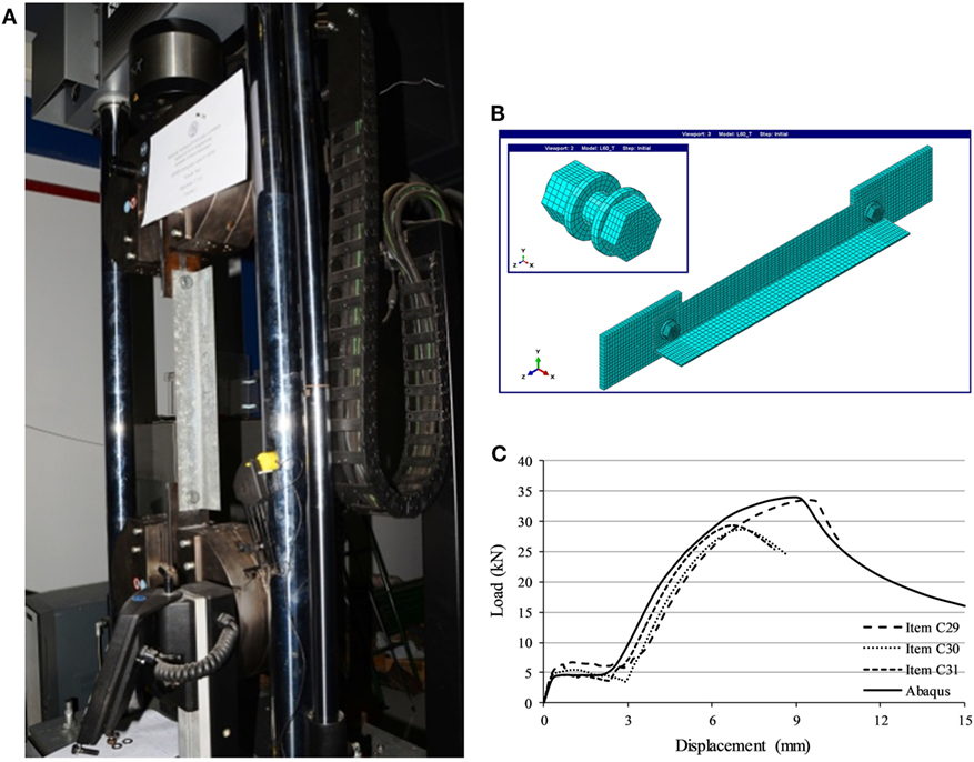
Figure 1. Overall view of (A) the tension set-up and (B) the Abaqus FEM, and (C) comparison of experimental and numerical buckling curves for cross section L45.
Given that crucial geometric imperfections were observed, their detailed measurement was deemed necessary. For this reason, a 2D Deformation Plotter (DP) was designed and constructed by the Laboratory technicians. The DP scanned the specimen’s deformation, by monitoring simultaneously the displacements of both angle legs, as well as the longitudinal coordinate. A more detailed description of the procedure will be presented in a future study.
Finite Element Simulation
The Abaqus finite element software is employed for the numerical analyses Abaqus/CAE (2015). The material parameters follow a simplified multi-linear model according to the tensile coupon test results, whereas no cold-form effects (residual stresses/strains) are taken into account in the current study. A “perfect” specimen geometry is introduced, in order to examine the effect of geometric imperfections found in the angle members. However, the geometrical non-linearities due to large displacements are considered into the FE analysis framework through the calculation of the updated stiffness matrix at the end of each loading increment. The boundary conditions are considered fixed for the outer edges of the endplates, perpendicular to the longitudinal axis of the beam.
Furthermore, 14 contact interactions are considered using surface-to-surface contacts between the parts: bolt–nut–washer–angle–plate. More specifically, exponential pressure-overclosure normal curve and tangential behavior with penalty formulation are considered. In addition, tied constraint is used for the case of bolt–bolt nut contact. Interesting details are included in Brunesi et al. (2014), about the contact conditions simulation as well as the bolt pretension. Some simplifications are allowed to be used in order to overcome convergence difficulties. In the absence of more information, one may use the 70% of the tensile strength as a bolt pre-load, according to EN 1993-1-8 (CEN, 2009d), as noted in Kettler et al. (2017). As for its effect on the load carrying capacity, previous work of Zhuge et al. (2012) states that moderate pre-tensioning force produced the more accurate results when dealing with starred angle sections. This factor will be addressed by the authors on a future research.
C3D8R solid elements are selected for the simulation of the endplates, nuts, bolts and washers, while C3D8I elements (with incompatible deformation modes) are preferred for the angle members. A finite element model is presented in Figure 1B, where one can observe the mesh geometry. The bolted connection components, which are positioned concentrically to the hole at the beginning of the analysis, can also be noticed. A displacement-controlled analysis is used taking into account non-linear geometric effects; in correspondence with the test set-up, the displacement is applied to one of the end plates toward the longitudinal direction.
Results
Figure 1C presents the response curves (in terms of imposed force-elongation) for the case of L45 cross section under compression, from both the experimental and numerical analyses. One can obtain the various horizontal offsets between the experimental curves and also compared to the Abaqus equilibrium path. The latter is attributed to the prior position of the bolts. Nevertheless, the buckling curves seem not to be affected by the aforementioned observation, whereas the overall response is well predicted.
In Figures 2A,B, one can compare the tensile test results with the corresponding Eurocode 3 (EN 1993-1-8 and EN 1993-1-3) provisions and the numerical results of the Abaqus finite element model, respectively. The failure loads showed a small deviation from the codes (with EN 1993-1-8 being more conservative than EN 1993-1-3) and the numerical capacities. A more sophisticated finite element model, incorporating the cold-formed effects, should be employed, since bigger capacities have been obtained in previous work of the authors (Fasoulakis et al., 2016). In addition, damage mechanics that will allow the crack formation for the case of bearing failure in tension tests, as well as the pre-tensioning force, can be also taken into account.
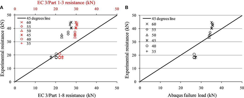
Figure 2. Comparison of tension experimental results with (A) the EN 1993 provisions (B) the numerical analyses.
In order to investigate the Eurocode 3 predictions, an indicative survey is followed herein for the case of compression. Results show that taking into account the interaction of compression and bending moments per the EN 1993-1-1 leads to conservative results and definitely is not the case for the present study. EN 1993-1-3 performs less conservative results for the case of interaction. Particularly, the small cross sections (L35, 40) are insensitive to local or distortional buckling, which allows an increase of the yield strength (leading here to unsafe results). On the contrary, the design capacities are close to the experimental ones when only the second-order effects are considered for the gross cross-sectional area. The last observations can be easily noticed in Figures 3A,B, whereas in Figure 3C one can obtain the dimensionless experimental capacities over the slenderness range, along with the buckling curve b per the EN 1993-1-1 and the reduced one for single-bolted angles per the EN 1993-3-1. EN 50341-1 notes that in case the analysis is not supplemented with full-scale experimental tests, buckling curve c should be used for the design resistance. For this reason, the latter curve is also attached in Figure 3C.
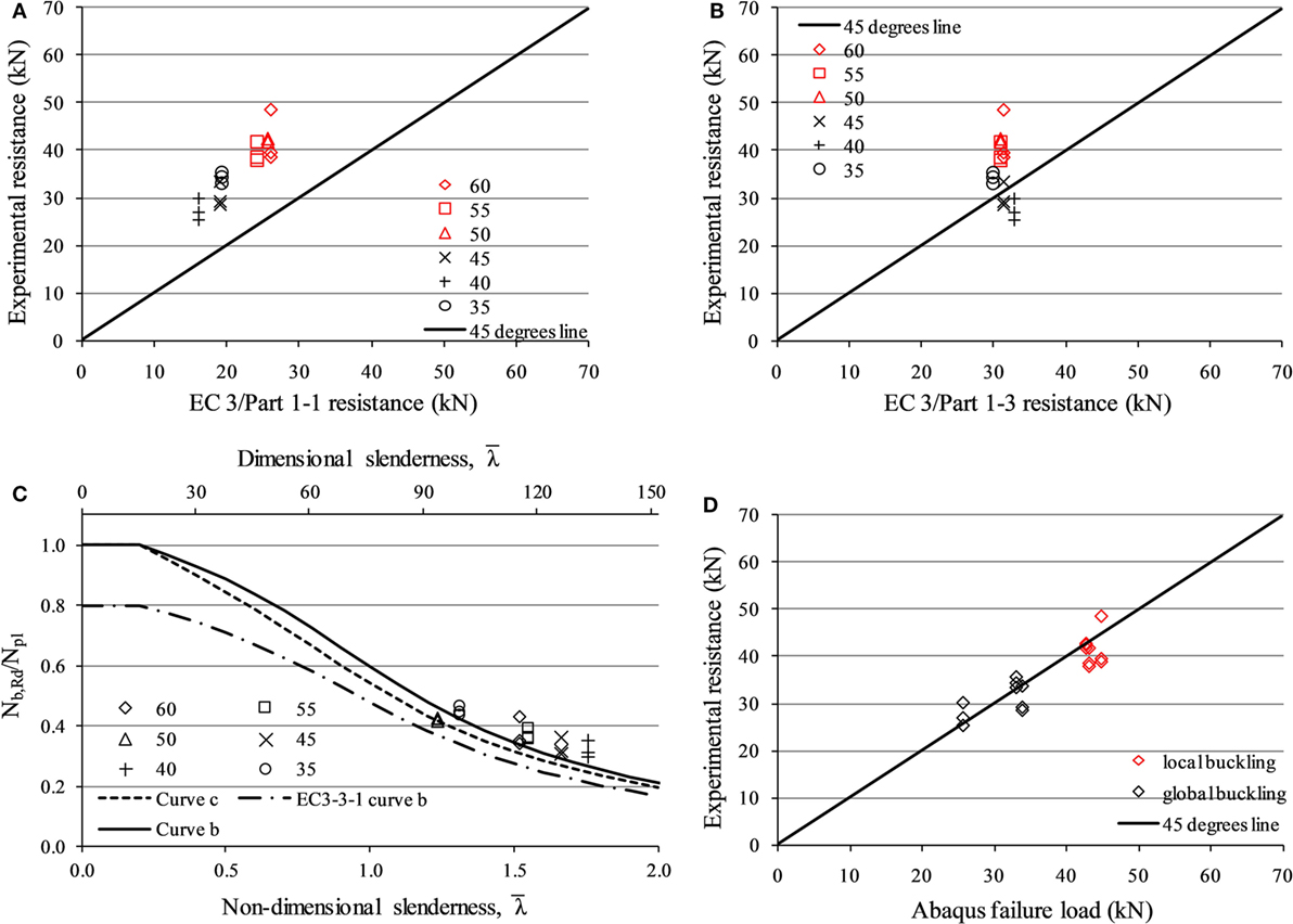
Figure 3. Comparison of compression experimental results with the predictions of (A) the EN 1993-1-1, (B) the EN 1993-1-3, (C) the EN1993 for compression only, and (D) with the numerical analyses.
For the case of compression, the computational results are in good agreement with the experimental ones (Figure 3D), while the buckling configuration is observed also in correlation. In particular, the non-slender sections L35, 40, and 45 deformed in a global buckling collapse mode, while the more slender sections L50, 55, and 60 failed under local buckling effects. The initial geometric imperfections (which reached out-of-straightness amplitudes greater than L/700) explain the lower experimental resistance loads compared to the numerical ones. In addition, two specimens exhibited greater failure loads than the corresponding FEA most probably due to greater cross-sectional thickness than the nominal (average) one. Particularly, specimens C26 and C12—with 3.4-mm thickness—recorded 17 and 8% greater buckling capacity than the ones obtained numerically.
Finally, a reliability analysis was performed for the compression tests according to the American Iron and Steel Institute (2016). Particularly, the reliability index was observed between 2.3 and 4.7, giving probability of exceeding the limit state approximately equal to 10−2 to 10−6, respectively. The lowest reliability is observed for the group of tests with the largest deviation from the average value, i.e., 16% for the L60 sections. Actually, the specimen that deviated recorded greater buckling capacity than the average one and it can be observed in Figures 3A,B,D (rhombus point with the greater experimental resistance). The reliability index values for the rest sections were observed over 3.4.
Conclusion
The investigation followed herein revealed interesting conclusions about the capacity of cold-formed angles in tension and compression. The code predictions can be improved to a minor extent, when addressing bolted cold-formed angle columns. Simple and more accurate design models can be adopted, avoiding the beam-column approach, proposed by the EN 1993-1-3. The numerical results showed good approximation with the experimental ones. More sophisticated simulations can be undertaken, though. Further research activities have been launched by the authors with regard to the geometric imperfections and the finite element model and will be presented in a more thorough future work.
Author Contributions
ZF carried out the numerical analyses and prepared the results. IR supervised the theoretical background and along with TA organized the research process. All authors contributed equally on the interpretation of the data for the current work.
Conflict of Interest Statement
The authors declare that the research was conducted in the absence of any commercial or financial relationships that could be construed as a potential conflict of interest.
Acknowledgments
The angle specimens were provided by the Independent Power Transmission Operator of Greece; therefore, the organization is kindly acknowledged by the authors.
Funding
First author would like to express his appreciation for the fee waiver grant by Frontiers Publishing Grants.
References
American Iron and Steel Institute. (2016). North American Specification for the Design of Cold-Formed Steel Structural Members. Washington, DC: CSA Group.
Brunesi, E., Nascimbene, R., and Rassati, G. A. (2014). Response of partially-restrained bolted beam-to-column connections under cyclic loads. J. Constr. Steel Res. 97, 24–38. doi: 10.1016/j.jcsr.2014.01.014
CEN. (2009a). Eurocode 3: Design of Steel Structures – Part 1–1: General Rules and Rules for Buildings. Brussels: European Committee for Standard.
CEN. (2009b). Eurocode 3: Design of Steel Structures – Part 1–3: General Rules – Supplementary Rules for Cold-Formed Members and Sheeting. Brussels: European Committee for Standard.
CEN. (2009c). Eurocode 3: Design of Steel Structures – Part 1–5: Plated Structural Elements. Brussels: European Committee for Standard.
CEN. (2009d). Eurocode 3: Design of Steel Structures – Part 1–8: Design of Joints. Brussels: European Committee for Standard.
CEN. (2009e). Eurocode 3: Design of Steel Structures – Part 3–1: Towers, Masts and Chimneys – Towers and Masts. Brussels: European Committee for Standard.
Fasoulakis, Z., Raftoyiannis, I., Avraam, T., and Papadopoulos, V. (2016). “Stability investigation of single bolted members from colf-formed angle sections with random imperfections,” in Proceedings of the 11th HSTAM International Congress on Mechanics (Athens, Greece).
Kettler, M., Taras, A., and Unterweger, H. (2017). Member capacity of bolted steel angles in compression – influence of realistic end supports. J. Constr. Steel Res. 130, 22–35. doi:10.1016/j.jcsr.2016.11.021
Landesmann, A, Camotim, D., Dinis, P. B., and Cruz, R. (2017). Short-to-intermediate slender pin-ended cold-formed steel equal-leg angle columns: experimental investigation, numerical simulations and DSM design. Eng. Struct. 132, 471–493. doi:10.1016/j.engstruct.2016.11.034
Mohan, S. J., Shabeen, S. R., and Knight, G. M. S. (2006). Behaviour of cold formed lipped angles in transmission line towers. Thin Walled Struct. 44, 1017–1030. doi:10.1016/j.tws.2006.07.006
Popovic, D., Hancock, G. J., and Rasmussen, K. J. R. (1999). Axial compression tests of cold-formed angles. ASCE J. Struct. Eng. 125, 515–523. doi:10.1061/(ASCE)0733-9445(1999)125:5(515)
Prabha, P., Jayachandran, S. A., Saravanan, M., and Marimuthu, V. (2011). Prediction of the tensile capacity of cold-formed angles experiencing shear lag. Thin Walled Struct. 49, 1348–1358. doi:10.1016/j.tws.2011.06.003
Sun, J., and Butterworth, J. W. (1998). Behaviour of steel single angle compression members axially loaded through one leg. ASEC 98, 859–866.
Vishnuvardhan, S., and Knight, G. M. S. (2008). Behaviour of cold-formed steel single and compound plain angles in compression. Adv. Steel Constr. 4, 46–58. doi:10.18057/IJASC.2008.4.1.4
Young, B. (2004). Tests and design of fixed-ended cold-formed steel plain angle columns. ASCE J. Struct. Eng. 130, 1931–1940. doi:10.1061/(ASCE)0733-9445(2004)130:12(1931)
Keywords: bolted angles, cold-formed sections, experimental testing, tension, compression
Citation: Fasoulakis ZC, Raftoyiannis IG and Avraam TP (2017) Experimental and Numerical Study on Single-Bolted Cold-Formed Angles under Tension and Compression. Front. Built Environ. 3:75. doi: 10.3389/fbuil.2017.00075
Received: 10 October 2017; Accepted: 05 December 2017;
Published: 20 December 2017
Edited by:
Konstantinos Daniel Tsavdaridis, University of Leeds, United KingdomReviewed by:
Chrysanthos Maraveas, University of Liège, BelgiumEmanuele Brunesi, European Centre for Training and Research in Earthquake Engineering, Italy
Copyright: © 2017 Fasoulakis, Raftoyiannis and Avraam. This is an open-access article distributed under the terms of the Creative Commons Attribution License (CC BY). The use, distribution or reproduction in other forums is permitted, provided the original author(s) or licensor are credited and that the original publication in this journal is cited, in accordance with accepted academic practice. No use, distribution or reproduction is permitted which does not comply with these terms.
*Correspondence: Zacharias C. Fasoulakis, emFmQGNlbnRyYWwubnR1YS5ncg==