 Huajie Wen
 Hussam Mahmoud
- Department of Civil and Environmental Engineering, Colorado State University, Fort Collins, CO, United States
In eccentrically braced frames (EBFs) subjected to large lateral demands, inelastic actions are mostly concentrated in shear links. The links vary in size and, when employed in frames, are known to be subjected to combined tension/compression and shear stress states that influence their strength, low-cycle fatigue behavior, and fracture characteristics. Despite their significance as the main energy dissipation elements in a structure subjected to seismic demand, simulating their full response, including the number of cycles to failure, of these links as individual components, or when employed in full frames, is lacking. This is primarily because until recently, most low-cycle fatigue models did not allow link failures under complex stress states to be captured. In this study, by means of a well-established ultra-low cycle fatigue (ULCF) criterion, the behavior of these links is fully assessed. The focus is on short shear links since they are widely used in comparison to intermediate or long links. Results of the simulations are compared with their experimental equivalents and excellent comparisons are achieved, confirming the validity of the simulation methodology and providing, for the first time, a framework for simulating the ULCF behavior of shear links. The verified response prediction methodology is then applied at the structural level, and non-linear pushover analysis on EBFs is conducted. Unlike the existing numerical approaches where failure is indicated through a prescriptive target performance, such as 5% interstory drift for collapse prevention, the pushover analysis is conducted until complete fracture of the links and failure of the system. Seismic design parameters, such as deign and elastic base shears as well as force reduction factors, are also determined based on the pushover curves. The results demonstrate that the proposed approach can reliably predict the performance of EBFs and can potentially be used in future design and analysis of such frames.
Introduction
Shear links are widely used in steel eccentrically braced frames (EBFs) for seismic protection. Short links are preferred since under severe cyclic loading conditions their performance is considerably better than intermediate and long links. Despite their stable performance, recent experimental test results have shown short links, designed using current criterion and fabricated from modern steel grades, to be prone to web fracture prior to the occurrence of any significant out-of-plane buckling (Arce, 2002; Okazaki and Engelhardt, 2007). This is different from tests conducted in 1980s, in which end local buckling of the links was shown to be the dominate failure mode (Kasai and Popov, 1986; Popov and Engelhardt, 1988). The unexpected web fracture usually occurred at the termination of web stiffener welds. Because of these premature failures, the deformation capacity of the links could not meet the standard minimum plastic rotation requirement of 0.08 rad under conventional cyclic loading history defined in Appendix S of AISC 341-02 [American Institute of Steel Construction, Inc. (AISC), 2002]. Achieving this level of rotation was not realized until less severe but more reasonable testing protocol was developed by Richards and Uang (2003), which was later adopted by AISC 341-05 [American Institute of Steel Construction, Inc. (AISC), 2005].
To understand web fracture, and subsequently improve the performance of the links, several researchers evaluated the reason for fracture initiation at the stiffener welds terminations. Okazaki and Engelhardt (2007), through a comprehensive experimental program, concluded that the web fracture mode was little affected by the loading history and stiffener detail. It was also noted that the relationship between the link web fracture and material properties, such as the k-area, is unclear. On the other hand, the welding process used for attaching the stiffener to the web was shown to have significant impact on the resistance of the link web to fracture, but not on the fracture modes or path. Galvez (2004) found that stiffened links, in which the stiffeners are only welded to the link flange but not the web, are far less prone to fracture than typical links where the stiffener is welded to the web. This, to some extent, indicates that the welding process may be relevant in understanding the reasons for premature fracture. Chao et al. (2006) conducted finite element (FE) analysis to evaluate fracture potential of the web using a monotonically loaded specimen in the experimental program by Okazaki and Engelhardt (2007). With the application of a basic ductile fracture criterion, it was noted that the termination of stiffener welds is the location with the highest potential for fracture because of the existing high triaxial constraint and elevated local strain demand. The higher triaxial and strain demand explanation correlates with the conclusion drawn by McDaniel et al. (2003), in which it was indicated that brittle fracture in the links is due to insufficient distance between the stiffener-to-web weld and the k-line. However, through experimental tests, Okazaki et al. (2004) indicated that increasing the distance would not eliminate this type of fracture entirely, although larger distances did lead to larger rotation at fracture. This, somehow, excludes the effect of k-line from the possible causes of fracture, since fracture still occurs in links with large distance between the stiffener weld termination and the start of the k-line areas. Therefore, it is not imprudent to conclude that the premature fracture is mainly attributed to the welding process and stress states.
From previous experimental results, it was speculated/concluded that the cause of web fracture at the stiffener weld termination may be attributed to local triaxial constraint, fracture resistance of k-line, and the welding procedure. The complexity and the interaction of these parameters, coupled with the high costs associated with experimental testing, necessitate the development of advanced FE models that can allow large number of analyses to be conducted so that detailed assessment can be made. While conventional FE analysis can provide useful information on the stress and the strain states, along with problematic regions (i.e., hotspots), they are not sufficient to evaluate the full ultra low cycle fatigue (ULCF) response of the links including fracture initiation and progression. In ULCF, failure occurs after very limited cycles, mostly less than 100, which is typical of these links, after significant reverse plastic straining. The key factor differentiating ULCF and traditional fatigue is the significant plastic deformations prior to the final occurrence of fracture. The large plastic deformations simply invalidate the foundations of traditional fatigue, which is based on linear elastic fracture mechanics (Kanvinde, 2004; Wen and Mahmoud, 2016b). ULCF belongs to the category of ductile fracture, where the fracture profile can be described using monotonic loading failure phenomenon (Kanvinde and Deierlein, 2007; Wen and Mahmoud, 2016a). Hence, ULCF should and does share similar characteristics to that of ductile fracture under monotonic loading in which the stress state is influenced and controlled by plastic strain. Several ductile fracture criteria have been developed to describe failure under monotonic loading and few of which were further extended to include the cyclic loading effects associated with ULCF. Among these is the recent criterion developed by Wen and Mahmoud (2016a) under monotonic loading, which has been extensively validated through comparison with experimental results of coupons (Wen and Mahmoud, 2016a) and applied to practical structural connections under monotonic loading conditions (Wen and Mahmoud, 2017). The Wen–Mahmoud model (Wen and Mahmoud, 2016a) was further extended on the coupon level to the case of cyclic loading to include the effect of loading history and non-linear damage accumulation (Wen and Mahmoud, 2016b) and is being assessed in this study to evaluate its appropriateness for simulating ductile fracture under cyclic loading on the member level (shear links), as will be discussed in detail.
Proper modeling of failure of shear links can provide amble opportunities for exploring the full behavior of EBFs. Non-linear time-history analysis is the most preferred approach for seismic analysis of structures but is known to be computationally demanding, especially when fracture simulations are included. In practice, non-linear pushover analysis has been widely used and accepted as the substitute. Over the years, the pushover analysis has progressed from force-controlled approaches to displacement-based adaptive pushover methods to allow for full capturing of system response, which is explored in this study on two EBFs.
In this study, we begin by introducing the Wen–Mahmoud ductile fracture and ULCF criterion as well as the associated damage accumulation rules. Simulations of fracture at the component level are first conducted on shear links with geomaterial characteristics similar to those previously tested experimentally. The component-level analysis accounts for the effect of residual stresses and the heat-affected zone (HAZ) from the welding process through alteration of the material resistance to fracture where appropriate. Validation analysis for the abovementioned numerical procedure is conducted through comparisons between the simulations and the corresponding experimental tests, in the perspective of load versus deformation response, fracture initiations and propagations, as well as the number of cycles to failure. Following assessment at the link level, the analysis is extended to the structural level where non-linear adaptive pushover analyses for one- and two-story EBFs are numerically performed through simple but uniquely designed displacement-controlled method. The pushover results are conducted up to and including fracture of the links and failure of the system. The results are utilized to highlight the relevance of the analysis in extracting and calculating relevant and accurate seismic design parameters such as elastic base shear, design base shear, and ductility reduction and overstrength factors.
ULCF Criterion
Attempts to accurately predict ductile fracture of metals have begun since 1950s. The dependency of ductile fracture on stress triaxiality has already been identified and modeled before 1980s. However, the dependency on Lode parameter has not been realized until very recent experimental studies (Bao, 2003; Bao and Wierzbicki, 2004; Wierzbicki et al., 2005; Bai, 2008). Thus, most existing ductile fracture models only include the effect of stress triaxiality and are only capable of capturing tension failure.
Recognizing the importance of Lode angle on ductile fracture, Bai and Wierzbicki (2008, 2010), among others, developed ductile fracture models that account for the combined effect of triaxiality and Lode angle. Wen and Mahmoud (2016a) proposed a simpler three-parameter ductile fracture criterion, with consideration to both the stress triaxiality η and Lode angle parameter as well as strong applicability in the entire range of stress states. The three parameters are designed to capture the unique and independent effects of the two stress state parameters and are much easier to calibrate than the equivalent criterion in the study by Bai and Wierzbicki (2008, 2010). The Wen–Mahmoud ductile fracture criterion is shown in Eq. 1:
where is the plastic strain at fracture and c1 to c3 are the three parameters that require calibration. For material under proportional or quasi-proportional loading conditions, the stress triaxiality and Lode angle parameter remain nearly constant with the varying plastic strain. Therefore, Eq. 1 can be directly used to calculate the fracture strain. However, for material under non-proportional loading conditions, fracture can be determined using the linear damage evolution rule described by Eq. 2, where is the equivalent plastic strain. The fracture is presumed to occur when the damage, D, reaches or exceeds a value of one. The criterion has been successfully applied in predicting and simulating block shear in gusset plate and coped beam connections in the study by Wen and Mahmoud (2017):
Under reverse loading, a non-linear damage accumulation rule was proposed by Wen and Mahmoud (2016b) based on Eq. 1, expressed in Eq. 3, shown as:
where c4 captures the loading history effects, κ describes the effects from previous plastic strain excursions, and m accounts for damage accumulation non-linearity. It is assumed that damage will develop along with the absolute value of plastic strain variation. The fracture criterion is applied in this study through a user-defined subroutine, VUMAT, and elements whose damage variable reaches one are deleted from the mesh. Figure 1 shows a flowchart describing the VUMAT process for capturing the ULCF, where p is another denotation of , σ is the stress tensor, ɛ is the strain tensor, α is the back stress tensor, σtr is the trial stress tensor, r() is the backstress function, and ɛpl is the plastic strain tensor.
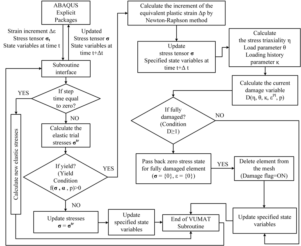
Figure 1. Flow chart for VUMAT of the ultra low cycle fatigue criterion.
Numerical Simulations of Shear Links
Description of the Simulated Shear Links
The shear links in the experimental program by Galvez (2004), shown in Figure 2, are used for the numerical simulations in this study. It is noted that this experimental setup was used by other members of the research team as shown in the studies by Okazaki (2004) and Okazaki et al. (2005) for further tests on shear links. There were a total of 10 links in this program, including 8 specimens with stiffeners welded to link webs, and 2 specimens with web pinched by stiffeners (i.e., stiffener is not welded to the web). Since the objective of this current study is to explore the premature fracture of the web, which initiates at the termination of the stiffener weld, the two links without welding on webs are not included. Another specimen is excluded since its geometry was significantly different from the others. Therefore, the total number of simulated specimens is seven. Two loading protocols are utilized in this study in which the first protocol is the conventional cyclic loading history in Appendix S of AISC 341-02 [American Institute of Steel Construction, Inc. (AISC), 2002], named the Severe Loading Protocol (SLP), and the other is the one developed by Richards and Uang (2003), which can be found in AISC-05 [American Institute of Steel Construction, Inc. (AISC), 2005] and is named the Revised Loading Protocol (RLP).
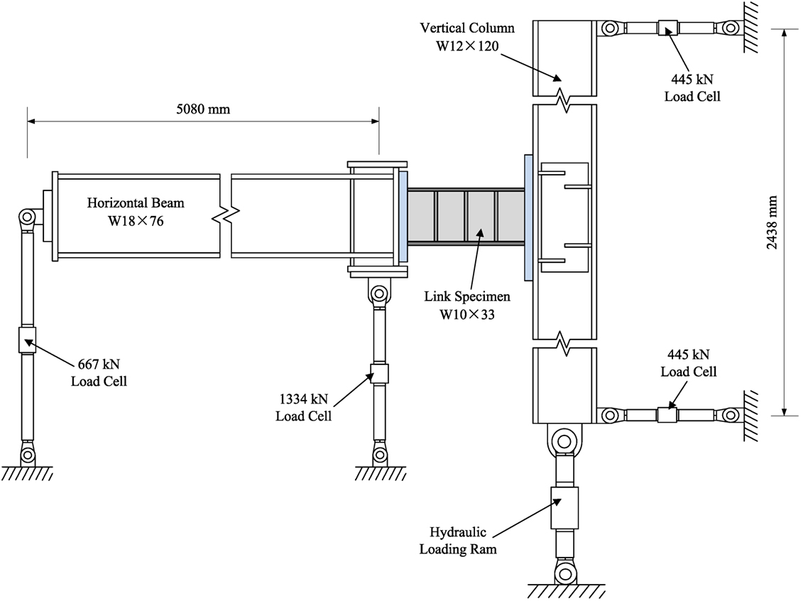
Figure 2. Details and dimensions of the test setup in the studies by Galvez (2004), Okazaki (2004), and Okazaki et al. (2005): redrawn from Galvez (2004).
Of the seven simulated specimens, the first three links included one-sided stiffeners and were all loaded under SLP. These three specimens had the same geometry and steel grade, ASTM A992 Gr. 50, but were obtained from different manufacturers. Therefore, only one numerical model is built for the three specimens since they share the same characteristics except possible slight material difference. This model is named as specimen I. There are three other specimens that also share the same geometry and include two-sided welded stiffener, one of which was uniquely fabricated using shielded metal arc welding (SMAW). For all other specimens, the stiffeners were welded using self-shielded flux-cored arc welding (FCAW), which is expected to produce lower heat input than SMAW. The link fabricated using SMAW is named specimen III and is loaded using the SLP. The other two specimens with two-sided stiffeners are named Specimens II and V and are loaded with the SLP and RLP. The only remaining specimen includes one-sided stiffener that is not welded to the flange, named Specimen IV, and loaded through the SLP. Therefore, in total five different numerical models that include three different geometries under two different loading protocols are developed to represent seven previously tested specimens. Details of link configurations and geometries are shown in Figure 3.
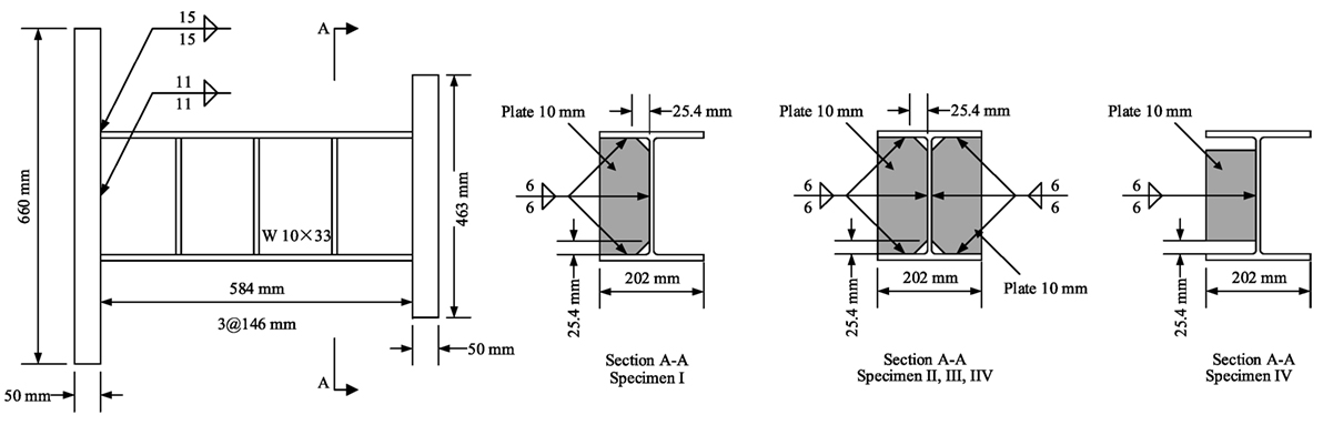
Figure 3. Geometry configurations and welding details for the simulated specimens.
General Modeling Approach
The general-purpose FE program ABAQUS/Explicit (Simulia Dassault Systèmes, 2012) is employed in the current study. For the purpose of reducing the computational demand, multiscale modeling technique is adopted. As shown in Figure 4, the beam and column are modeled using 3D beam element B31, while the link is modeled with 3D shell element S4R, and the welds are modeled with 3D solid element C3D6T. Each link includes 5,540 shell elements, and each weldment is composed of 16 solid elements. The beam and link are connected through coupling constraint, and the column is attached to the link by a series of multi-point constraints (MPCs). The weld is modeled using solid element with temperature, to accommodate the inclusion of the HAZ, and solid-shell coupling is achieved through MPC between the weld and web/stiffeners. In the concerned areas of the link webs, which have high fracture possibilities, a refined mesh size of 1.5 mm × 1.5 mm resolution is employed. For the sake of computational efficiency, only the link webs’ material model is defined using the VUMAT, while material for other parts of the model is defined using the available models in ABAQUS. The VUMAT material model hardening parameters are shown in Eqs 4 and 5a,b, where σ′ is the deviatoric stress tensor, and σy0 = 360 MPa is the yielding stress. Since there is no sufficient information regarding the material used for testing, the fracture parameters for a similar steel grade, ASTM 572 Gr. 50, calibrated in the study by Wen and Mahmoud (2016b) are used in the present study. The combined hardening material model embedded in ABAQUS is employed for structural components that are not susceptible to fracture, such as beam and columns:
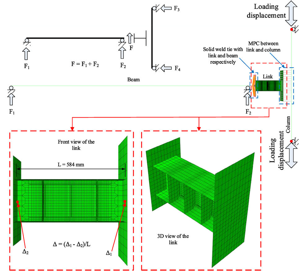
Figure 4. Typical numerical model.
The loading procedure used in the simulations is identical to that of the laboratory tests. The welding process, mainly in terms of the heat effects, can influence the adjacent base material in two ways, namely addition of residual stresses and alternation of properties in the HAZ. In the present study, the weld-induced residual stresses are applied to the base metal through specifying initial stresses representing the expected stress field, following one of the most popular representations, which was proposed by Dwight and Moxham (1969) and later modified by Faulkner (1975). This approach has been previously implemented and well verified as noted in the studies by Dexter et al. (2003, 2005), Mahmoud and Dexter (2005), and Mahmoud and Riveros (2014). With respect to traditional fracture mechanics, the local stress state at the crack tip, comprising residual stresses and in-service stresses, is quite important, and therefore, the inclusion of residual stresses in the model is critical for accurate predictions. During cyclic loading, the presence of residual stress influences the mean stress for high cycle fatigue and strain amplitude and mean strain for traditional low cycle fatigue, hence greatly affecting fatigue life. For ULCF, however, the effect of residual stresses is insignificant since they are removed by plastic deformations and are no longer present immediately prior to the onset of fracture. This is because initial plastic deformations are relaxed or redistributed after certain strain excursion. The residual stresses indeed lead to a “softer” load–deformation curve during the first loading cycle (shakedown), but the curves return back to the ones without consideration of residual stresses only after three cycles, in which the link web is still in the elastic range. This implies that the inclusion of residual stresses resulted in negligible additional difference since damage evolution is not even initiated in the first several elastic cycles. The insignificant effect of residual stresses on ductile fracture was also noted by Radaj (2012).
The HAZs
Although the effect of residual stresses on ductile fracture is insignificant, fracture resistance of welded structures is admittedly degraded while strength is actually increased in most cases. The degradation arises from the exposure to temperature during the welding process. The HAZ is the area of base metal that does not melt but has its microstructure and mechanical properties altered by the intensive heat induced by welding or flame cutting operations. The heating and subsequent cooling both cause changes in properties within the zones located from the weld interface to the boundary of the sensitizing temperature of base metal. The extent of change depends on many factors; primarily, the heat amount and input rate, the cooling environment, and the subject metals. It is important to note that compared to the entire components, the relative dimension of the HAZ is very small, and hence the global behavior of the link will not be greatly influenced by altering the material properties in HAZ. However, the effect of HAZ on the fracture phenomenon and the number of cycles to failure, where local crack initiation may be located in the HAZ, may be significant.
Many common mechanical properties, including yield stress, elastic modulus, ductility, and hardness, are changed after the material experiences thermal cycles. Since the characteristics of these properties vary as a function of distance from the heat source, the material in the HAZ becomes heterogeneous. Therefore, the material and damage parameters calibrated for base metal cannot be directly applied to the HAZ material. Since the HAZ is greatly restrained and usually not exceed the web thickness, a one meshed element of 1.5 mm × 1.5 mm is used to represent an average material property change in the HAZ.
Generally, the resistance to fracture in the HAZ is degraded by thermal cycles and the loss of fracture capacity, described as loss of toughness in traditional fracture mechanics, is mainly due to the formation of local brittle zones, which are believed to be due to the presence of martensite–austenite (M-A) islands. The microstructure of the base metal will be changed if the thermal cycles exceed some certain transformation temperature in the HAZ. As shown in Figure 5A, for single pass weld, the HAZ microstructures can be broadly categorized into four regions as (1) coarse grain HAZ (CG HAZ), (2) fine grain HAZ (FG HAZ), (3) intercritical HAZ (IC HAZ) or partially transformed HAZ, and (4) subcritical HAZ (SC HAZ) or tempered HAZ [American Petroleum Institute (API), 1986]. There are no sharp transitions between each zone. The microstructure of HAZ is very complicated. For low-carbon steel, whose original microstructure is ferrite/pearlite, in the CG HAZ, the original steel is transformed and more or less characterized by quenched microstructure of bainite/martensite, and austenite grains also grow with increasing peak temperature, followed by a subsequent microstructure coarsening. The FG HAZ comprises fine ferrite grain structure, from the normalizing heat treatment. In the IC HAZ, the pearlite is only partially transformed to ferrite due to the reduced temperature. In the SC HAZ, there is no microstructure change since the temperature is not high enough, and the base metal only undergoes thermal treatment. In the case of a multipass weld, the HAZs are reheated by the subsequent cycles, and the microstructure may be altered again significantly with more complicated transformation mechanism and more regions produced. The difference between single pass and multipass weld lies in the fact that the original microstructure has transformed from the original ferrite/pearlite to maybe bainite/martensite of CG HAZ. With another high thermal cycle, more martensite and austenite forms, which means that more M-A brittle islands are produced. It has been previously shown that the reheated coarse grain HAZ (IRCG HAZ) is the most degraded zone among these regions (Homma et al., 1998), as shown in Figure 5B, which shows the classifications for multipass weld. The web fracture initiation of the shear links lied at the termination of stiffener welds, which are exactly located at the zones influenced by both welds on the two sides of a stiffener on the same web face, and should be further degraded than vertical zones along the welds.
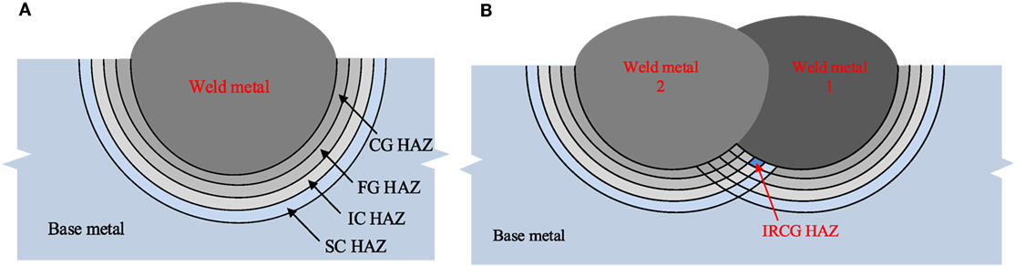
Figure 5. Classification of heat-affected zone (HAZ): (A) single pass weld and (B) multipass weld.
There is no well-accepted quantitative definition of the level of fracture resistance degradation of HAZs. In addition, related studies are scarce and include diverse and mixed conclusions. For ULCF or ductile fracture, Tateishi and Hanji (2004) indicated that crack initiation life in the HAZ was only around 30% of the life of the base metal. Liao et al. (2012), on the other hand, only noted slight degradation, which might be attributed to the fact that all the samples included material not only from HAZs but also from transition zones and base metal. In the present study, the degradation factor for damage parameters of certain HAZ locations is qualitatively calibrated and implemented in the numerical simulations. Although the quantification of such merits extensive future studies, no attempts are made to recommend a general degradation factor for all structural steel grades under different welding methods. In this study, a degradation factor of 0.8 is specified for HAZ under single-pass FCAW welding and 0.8 × 0.8 = 0.64 for HAZ under two weld pass, based on the results of Specimen I. For SMAW, the degradation factor for single- and two-pass weld is 0.56 and 0.32, respectively, based on the results of Specimen III. After calibration, the reduction factor for the FCAW process is then applied in simulating the response of Specimens II, IV, and V. The results of the simulations on individual shear links are compared to their experimental counterparts in terms of load–deformation curves, number of cycles to failure, and fracture initiation and propagation.
Shear Links Simulations Results
The Load–Deformation Behavior
As previously noted, seven specimens are evaluated in this study. The load versus deformation curves are shown in Figures 6A–D for Specimens I, III, IV, and V, respectively. The reason for showing only four responses is because Specimen I is equivalent to three experimental specimens, and therefore, the response of only one specimen is shown. In addition, since there is little difference between Specimens I and II, the curve for Specimen II is not included. In Figure 6, the load is the shear force applied to the EBF link, which can be calculated by summing the two reaction forces on the beam. The deformation, on the other hand, is monitored through link rotation, determined by the displacement difference between the two link ends over the link length. Inelastic/plastic rotation γp is usually used for assessment of link resistance to failure and can be determined from the total rotation γ, by Eq. 6, as follows:
where V is the link shear force, K is the elastic rotation stiffness, computed from the ratio of V and γ in the elastic cycles, which correspond to the first two steps in the present study. As shown in Figure 6, for all specimens, all simulated responses correlate exceptionally well with their experimental equivalents. Since one of the main goals of this study is to evaluate the ability to predict the ULCF life of the specimens, comparison of the experimental and numerical number of cycles to failure is shown in Table 1. As shown in the table, the predicted cycles to failure correlate very well with their experimental counterparts for all specimens with a very marginal error of merely 1 cycle in approximately 40 cycles. The numeral before the comma denotes the number of steps and the numeral following the comma denotes the number of cycles in the step. The symbol (±) denotes total completion of one cycle, while (+) denotes completion of only the first excursion of the cycle. For instance, 8, +3 indicates the specimen completed two cycles and failed after completing the positive portion of the third cycle during load step 8.
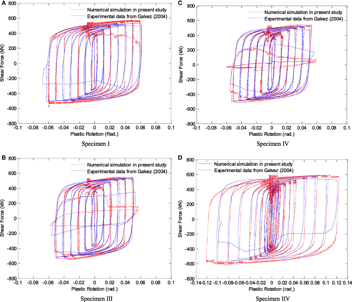
Figure 6. Comparisons of link shear force versus plastic rotation curves in numerical simulations and laboratory tests (experimental data from Galvez (2004)). (A) Specimen I, (B) Specimen III, (C) Specimen IV, and (D) Specimen V.
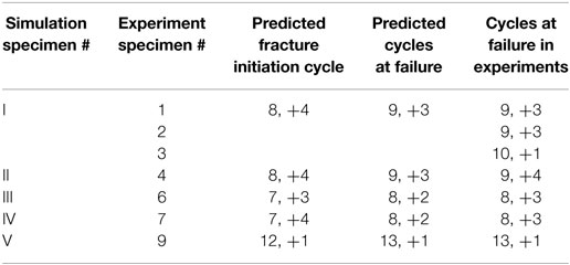
Table 1. Comparisons of the results between simulations and experiments.
The excellent correlation between the observed and the predicted cycles with failure further confirms the validity of the numerical modeling approach including the accuracy of the fracture parameters of the ULCF criterion, and the utilized HAZ degradation values. It is worth noting that closely simulating the load versus rotation response of members or connections has been previously conducted. However, it is the first time in numerical simulations where ULCF failure is predicted with such high level of accuracy.
Fracture Initiation and Propagation
The cycles to fracture initiation are also shown in Table 1. It is worth noting that for all specimens, first crack initiation occurs at the termination of the middle stiffener weld, at a step preceding the final failure step as shown for example in Figure 7A. Following fracture initiation, no degradation in strength is observed for additional few cycles as fracture progresses steadily. Only significant development of fracture may lead to strength loss, and intermediate fracture propagation only causes the strength to be maintained or its increase to be decelerated. Post the initiation cycle, the fracture is observed to progress mostly horizontally and later vertically with larger displacement required for the vertical progression.
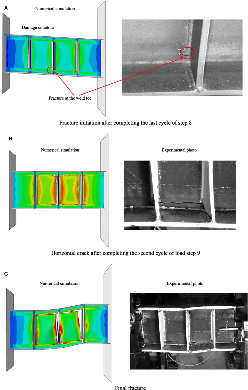
Figure 7. Comparisons of numerical versus experimental results for Specimen I (A) fracture initiation, (B) fracture propagation, and (C) final fracture [experimental photos from Galvez (2004)].
Comparisons between the numerical simulations and experimental tests, for Specimen I as a representative, are shown for fracture initiation in Figure 7A, fracture propagation in Figure 7B, and final fracture in Figure 7C. As the comparisons show, the fracture profiles obtained numerically agrees very well with their experimental equivalents.
Overall, the numerical simulations agree well with the experimental results in terms of load versus rotation curves, failure cycles, fracture initiations, and propagations. Therefore, it can be concluded that the numerical simulation methodology outlined in this study, that is (1) develop detailed and representative model of the links using appropriate multiscale techniques, (2) employ proper ductile fracture models that can allow for simulating of fracture up to and including failure, and (3) specify the correct damage parameters for the material in HAZs, is appropriate and can be utilized for accurate prediction of the full response of shear links and potentially for other structural details.
Pushover Analysis
In seismic design, explicit identification of the source of inelasticity in structural response is required for accurate estimation of energy absorption capacity of the system. For EBFs, ideally, evaluation based on a non-linear time-history analysis is the most accurate and can be accepted as the close-to-exact solution, if appropriate ground motions are selected. Since the focus of this study is on demonstrating the usefulness of the modeling approach and the entire framework, and in relation to existing guidelines such as FEMA P695 (FEMA P-695, 2009), non-linear pushover analysis is used instead to demonstrate the extension of the analysis to the frame level.
In numerical pushover analysis, a non-linear FE model of a given structure subjected to gravity loads is laterally proportionally loaded, until a target displacement is reached or collapse is imminent. In cases where large inelastic demand is expected, usually a prescriptive target performance is assigned, such as 5% interstory drift (IDR), to mark the onset of collapse without actually simulating failure. The pitfall of this approach is that it might be penalizing the frames that have the capacity to deform beyond the prescribed limit of 5% IDR or too forgiving and unconservative for frames that have limited deformation capacity. In pushover analysis on structures with multiple stories, the applied loads should be proportional to the equivalent mass of each floors, and hence, a force control solution scheme is more straightforward. However, under force control the applied force cannot continue to increase anymore when the load curve passes the peak point and the analysis terminates. As a result, a full load-displacement curve cannot be developed. To mitigate this issue, a displacement-based adaptive pushover method should be used. Anthoine (2006) proposed a simple but effective displacement-controlled method, which is utilized and illustrated in Figure 8. The load F in the two systems in Figures 8A,B has identical effects prior to reaching ultimate strength. After reaching the peak load, the simulation based on the loading system of Figure 8A cannot proceed. However, in the second system of Figure 8B, the loads in the form of displacement control can still be applied beyond the ultimate strength, and at the same time the forces applied on each floor are automatically distributed similar to that of Figure 8A since the loading beam is simply supported.
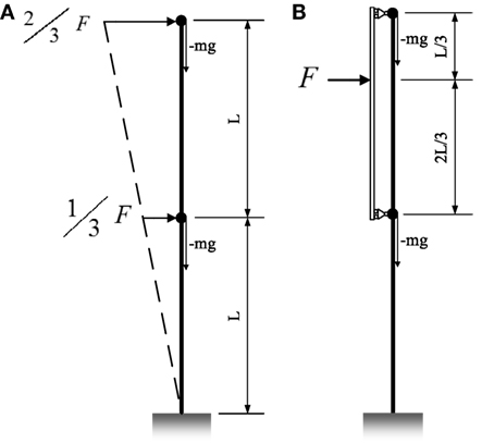
Figure 8. (A) Pushover analysis on a cantilever beam and (B) equivalent isostatic loading system.
Pushover analysis is conducted on one- and two-story EBFs. The two-story EBF is shown as a representative model in Figure 9. The one-story EBF has the same geometry and configuration as the first story of two-story EBF. The dead loads are applied on the beams. For the one-story pushover analysis, displacement is applied directly at the story height. For the two story EBF, the loads are applied through a system similar to that of Figure 8B. Multiscale modeling technique is used in which the frames are modeled with 3D beam elements B31, except for the shear links which are modeled identical to that of Specimen I discussed in the previous section. The links and constraints between the frame and links are also identical to that of Specimen I. Unless noted otherwise, all simulation settings in the frame pushover analysis are identical to that of the isolated shear links in the previous section.
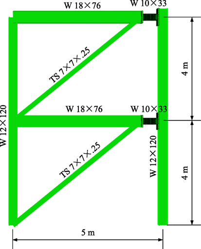
Figure 9. Numerical model and geometry of the two-story eccentrically braced frame.
The pushover curves are shown in Figures 10A,B for one- and two-story EBFs, respectively. For the two-story frame, fracture is observed for the link at the second-floor level. At the point of complete yielding of the links, which corresponds to design level base shear, versus, all other structural members remained elastic. When the links are further strained and subsequently fracture, minor inelastic behavior develops in the bottom of the column in the story with the failed link. The IDR for the one-story EBF is 2.86% and 2.57% and 3.58% for the first and second story, respectively, of the two-story EBF. Based on the obtained curves, the force reduction factors R in seismic codes, used to reduce the elastic base shear Ve to the design level base shear Vs, are determined, which can be defined as the product of the ductility reduction factor Rμ and the overstrength factor Rd. All of these parameters can be obtained from the pushover curves as illustrated in Figures 10A,B. There are two limit states defined in the analysis, complete yielding, corresponding to yield/design strength, and ultimate failure, corresponding to the ultimate strength, shown in Figures 10A,B. It is important to point out that after reaching the peak load point, the frames did not collapse immediately. Instead, the frames sustained their strength without significant loss for a notable displacement before total collapse, which is an overall confirmation of the design philosophy and the methodology for determining the force reduction factor.
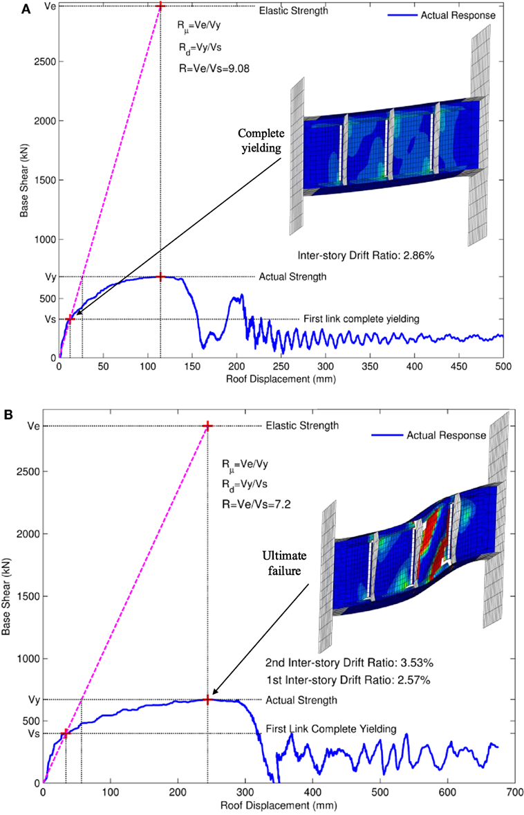
Figure 10. Pushover curves of (A) one-story eccentrically braced frames (EBF) and (B) two-story EBF.
Conclusion
In the present study, a well-established ULCF criterion is introduced then used to numerically simulate the failure mode of fracture, for the first time, in short shear links that are typically employed in EBFs. FE simulations of previously tested shear links were conducted up to and including complete failure, whose results are also extensively verified against their experimental equivalents. Excellent agreements were achieved in terms of load-versus displacement, number of cycles to failure, fracture initiation and propagation. The verified methodology was then applied to the frame level, and non-linear pushover analyses were conducted until complete fracture and system failure instead of relying on prescribed target displacements. Design characteristics, such as force reduction factors, were determined through the obtained pushover curves. Based on the simulations the following conclusions can be drawn:
1. The introduced methodology for simulating fracture in steel structures under reverse loading, by means of a well-established ULCF criterion, has been verified and can be applied for simulating failure in other structural components.
2. The main cause of fracture in short shear links in EBF has been identified as degradation of resistance to fracture in the HAZs. In the present study, this was accounted for through specifying reduction factors of 0.8 and 0.56 for FCAW and SMAW, respectively. Two or multipass welding will further degrade the fracture resistance in the HAZs. So careful attention should be made if a stiffeners is to be used to restrain possible out-of-plane deformations.
3. The pushover analyses on the EBFs were conducted using an adaptive displacement-controlled method. The results show the frame to undergo IDR less than 5% at the onset of failure.
4. Design parameters, such as force reduction factors and overstrength factors, were also able to be determined from the pushover analysis.
Author Contributions
HW conducted the study as part of his Ph.D. thesis. HM was the academic adviser of HW.
Conflict of Interest Statement
The authors declare that the research was conducted in the absence of any commercial or financial relationships that could be construed as a potential conflict of interest.
Funding
The work was in part funded by The US Department of Transportation under grant DTRT13-G-UTC38.
References
American Institute of Steel Construction, Inc (AISC). (2002). Seismic Provisions for Structural Steel Buildings. Standard ANSI/AISC 341-02. Chicago, IL: AISC.
American Institute of Steel Construction, Inc (AISC). (2005). Seismic Provisions for Structural Steel Buildings. Standard ANSI/AISC 341-05. Chicago, IL: AISC.
American Petroleum Institute (API). (1986). Recommended Practice for Reproduction Qualification for Steel Plates for Offshore Structures, First Edn. API Recommended Practice 2Z(RP 2Z). Dallas, TX: API Publishing Services.
Anthoine, A. (2006). A simple displacement control technique for pushover analysis. Earthquake Eng. Struct. Dyn. 35, 851–866. doi: 10.1002/eqe.560
Arce, G. (2002). Impact of Higher Strength Steels on Local Buckling and Overstrength of Links in Eccentrically Braced Frames. Master’s thesis. Austin, TX: University of Texas at Austin.
Bai, Y. (2008). Effect of Loading History in Necking and Fracture. Ph.D. dissertation. Cambridge MA: Massachusetts Institute of Technology.
Bai, Y., and Wierzbicki, T. (2008). A new model of metal plasticity and fracture with pressure and lode dependence. Int. J. Plast. 24, 1071–1096. doi:10.1016/j.ijplas.2007.09.004
Bai, Y., and Wierzbicki, T. (2010). Application of extended Mohr–Coulomb criterion to ductile fracture. Int. J. Fract. 161, 1–20. doi:10.1007/s10704-009-9422-8
Bao, Y. (2003). Prediction of Ductile Track Formation in Uncracked Bodies. PhD. dissertation. Cambridge MA: Massachusetts Institute of Technology.
Bao, Y., and Wierzbicki, T. (2004). On fracture locus in the equivalent strain and stress triaxiality space. Int. J. Mech. Sci 46, 81–98.
Chao, S., Khandelwal, K., and El-Tawil, S. (2006). Ductile web fracture initiation in steel shear links. J. Struct. Eng. 132, 1192–1200. doi:10.1061/(ASCE)0733-9445(2006)132:8(1192)
Dexter, R. J., Mahmoud, H. N., and Pilarski, P. J. (2005). Propagation of long cracks in stiffened box-sections under bending and stiffened single panels under axial tension. Int. J. Steel Struct. 5, 181–188.
Dexter, R. J., Pilarski, P. J., and Mahmoud, H. N. (2003). Analysis of crack propagation in welded stiffened panels. Int. J. Fatigue 25, 1169–1174. doi:10.1016/j.ijfatigue.2003.08.006
Dwight, J. B., and Moxham, K. E. (1969). Welded steel plates in compression. Struct. Eng. 47, 49–66.
Faulkner, D. (1975). A review of effective plating for use in the analysis of stiffened plating in bending and compression. J. Ship. Res., 19, 1–17.
FEMA P-695. (2009). Quantification of Building Seismic Performance Factors. Washington, DC: Federal Emergency Management Agency.
Galvez, P. (2004). Investigation of Factors Affecting Web Fractures in Shear Links. Master’s thesis. Austin, TX: University of Texas at Austin.
Homma, K., Miki, C., and Yang, H. (1998). Fracture toughness of cold worked and simulated heat affected structural steel. Eng. Fract. Mech. 59, 17–28. doi:10.1016/S0013-7944(97)00100-8
Kanvinde, A. M. (2004). Micromechanical Simulation of Earthquake-Induced Fracture in Steel Structures. Ph.D. dissertation. Stanford, CA: Stanford University.
Kanvinde, A. M., and Deierlein, G. G. (2007). Cyclic void growth model to assess ductile fracture initiation in structural steels due to ultra low cycle fatigue. J. Eng. Mech. 133, 701–712. doi:10.1061/(ASCE)0733-9399(2007)133:6(701)
Kasai, K., and Popov, E. P. (1986). General behavior of WF steel shear link beams. J. Struct. Eng. 112, 321–354. doi:10.1061/(ASCE)0733-9445(1986)112:2(362)
Liao, F., Wang, W., and Chen, Y. (2012). Parameter calibrations and application of micromechanical fracture models of structural steels. Struct. Eng. Mech. 42, 153–174.
Mahmoud, H., and Riveros, G. (2014). Fatigue reliability of a single stiffened ship hull panel. Eng. Struct. 66, 89–99. doi:10.1016/j.engstruct.2014.02.007
Mahmoud, H. N., and Dexter, R. J. (2005). Propagation rate of large cracks in stiffened panels under tension loading. J.Marine Struct. 18, 265–288. doi:10.1016/j.marstruc.2005.09.001
McDaniel, C. C., Uang, C. M., and Seible, F. (2003). Cyclic testing of built-up steel shear links for the new bay bridge. J. Struct. Eng. 129, 801–809. doi:10.1061/(ASCE)0733-9445(2003)129:6(801)
Okazaki, T. (2004). Seismic Performance of Link-to-Column Connections in Steel Eccentrically Braced Frames. Austin, TX: Mira Digital Publishing.
Okazaki, T., Arce, G., Ryu, H. C., and Engelhardt, M. D. (2005). Experimental study of local buckling, overstrength, and fracture of links in eccentrically braced frames. J. Struct. Eng. 131, 1526–1535. doi:10.1061/(ASCE)0733-9445(2005)131:10(1526)
Okazaki, T., and Engelhardt, M. D. (2007). Cyclic loading behavior of EBF links constructed of ASTM A992 steel. J. constr. steel Res. 63, 751–765. doi:10.1016/j.jcsr.2006.08.004
Okazaki, T., Engelhardt, M. D., Nakashima, M., and Suita, K. (2004). “Experimental study on link-to-column connections in steel eccentrically braced frames,” in Proceedings of the 13th World Conference on Earthquake Engineering (Vancouver, Canada: Mira Digital Publishing), 2004.
Popov, E. P., and Engelhardt, M. D. (1988). Seismic centrically braced frames. J. Constr. Steel Res. 10, 321–354. doi:10.1016/0143-974X(88)90034-X
Radaj, D. (2012). Heat Effects of Welding: Temperature Field, Residual Stress, Distortion. Berlin: Springer Science & Business Media.
Richards, P., and Uang, C. M. (2003). Development of Testing Protocol for Short Links in Eccentrically Braced Frames. San Diego, CA: Department of Structural Engineering, University of California.
Simulia Dassault Systèmes. (2012). ABAQUS FEA Version 6.12 [Computer software]. Providence, RI: Dassault Systèmes Simulia corp.
Tateishi, K., and Hanji, T. (2004). Low cycle fatigue strength of butt-welded steel joint by means of new testing system with image technique. Int. J. Fatigue 26, 1349–1356. doi:10.1016/j.ijfatigue.2004.03.016
Wen, H., and Mahmoud, H. (2016a). New model for ductile fracture of metal alloys. I: monotonic loading. J. Eng. Mech. 142, 04015088. doi:10.1061/(ASCE)EM.1943-7889.0001135
Wen, H., and Mahmoud, H. (2016b). New Model for ductile fracture of metal alloys. II: reverse loading. J. Eng. Mech. 142, 04015089. doi:10.1061/(ASCE)EM.1943-7889.0001009
Wen, H., and Mahmoud, H. (2017). Simulation of block shear failure in bolted connections. J. Constr. Steel Res. 134, 1–16. doi:10.1016/j.jcsr.2017.03.006
Wierzbicki, T., Bao, Y., and Bai, Y. (2005). “A new experimental technique for constructing a fracture envelope of metals under multi-axial loading,” in Proceedings, 2005 SEM Annual Conference and Exposition on Experimental and Applied Mechanics (Orlando: Society for Experimental Mechanics (SEM)), 1295–1303.
Keywords: eccentrically braced frame, shear link, fracture, ultra-low cycle fatigue, prediction
Citation: Wen H and Mahmoud H (2018) A New Approach to Predict Cyclic Response and Fracture of Shear Links and Eccentrically Braced Frames. Front. Built Environ. 4:11. doi: 10.3389/fbuil.2018.00011
Received: 28 November 2017; Accepted: 05 February 2018;
Published: 26 February 2018
Edited by:
Solomon Tesfamariam, University of British Columbia, CanadaReviewed by:
Emanuele Brunesi, European Center for Training and Research in Earthquake Engineering, ItalyMichele Palermo, Università di Bologna, Italy
Copyright: © 2018 Wen and Mahmoud. This is an open-access article distributed under the terms of the Creative Commons Attribution License (CC BY). The use, distribution or reproduction in other forums is permitted, provided the original author(s) and the copyright owner are credited and that the original publication in this journal is cited, in accordance with accepted academic practice. No use, distribution or reproduction is permitted which does not comply with these terms.
*Correspondence: Hussam Mahmoud, aHVzc2FtLm1haG1vdWRAY29sb3N0YXRlLmVkdQ==