 Raffaele Carabbio
 Luca Pieraccini
 Stefano Silvestri
 Martijn Schildkamp
- 1Department of Civil, Chemical, Environmental, and Materials Engineering, University of Bologna, Bologna, Italy
- 2Smart Shelter Research, Alphen aan den Rijn, Netherlands
After the 2005 M7.6 Kashmir earthquake (Pakistan), field observations reported that several buildings manufactured with local traditional techniques resisted well to that strong seismic event. In this paper, the attention is focused on a typical vernacular construction technique commonly named as “Bhatar,” still practiced in the Himalayan regions of India and Pakistan. It is grounded upon the “timber lacing” or “timber reinforcement masonry” concept, i.e., the combination of dry-stacked loose stones with timber beams to increase the wall confinement. Despite its good seismic performances, it has still not been deeply studied from a structural engineering point of view. This paper represents a first attempt to fill this gap. It presents a full analytical study on the structural behavior of a simple one-storey building unit characterized by a 3.6 m × 3.6 m square plan covered by a heavy wooden roof with 20-cm-thick earth coverage, in order to investigate its response under gravity and seismic inertial loadings. Materials properties, static analysis, and seismic analysis are discussed. In detail, Shorea Robusta wood and limestone rocks are identified as the most used construction materials for the Bhatar buildings. The Barton’s model is applied to characterize the shear strength of the rubble stone layers in the wall. Static analysis reveals that normal stresses at the ground level are around 92 kPa, which can be considered acceptable for common soils. With respect to earthquake, the Bhatar technique can absorb wall cracking and distortion mechanisms, and can dissipate energy through friction between stones. Under the assumption of no vertical ground motion, the acceleration which activates in-plane sliding mechanisms is found to be around 0.5 g, being dependent on the interface friction between adjacent layers. Some preliminary considerations about the out-of-plane seismic behavior are also provided concerning overturning and bending failure mechanisms. The results are based on assumptions taken by several authors and have not been verified with experimental tests. Nevertheless, some practical suggestions can be derived to improve the seismic shear strength and to ensure friction also in the case of significant vertical component of earthquake ground motions.
Introduction
In countries worldwide, including many Himalayan regions, examples can be found of load-bearing masonry with horizontal wood lacing, but without vertical reinforcement (Langenbach, 2009). For the wall material, generally bricks or stones are used, and the masonry is either constructed with mortar or dry-stacked, depending on local availability and preference (Figure 1). In the north of India the technique is called “Taq,” usually built with bricks and mud mortar. Nepal does not have local names for the techniques, whereas in Pakistan the technique is known as “Bhatar,” and the buildings predominantly consist of dry-stacked stone walls. According to Schacher (2007), the Pashto word “Bhatar” specifically indicates beams with a cross section of 3″–4″, which are then combined into continuous wooden ladders with cross pieces, used to reinforce the walls. In some cases, a weak mud or lime mortar is used, which may result in lower quality of masonry, as the masons take less care in proper placement of the stones (Dowling et al., 2007).
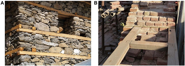
Figure 1. (A) Wooden bands and dry-stacked rubble stone masonry (photo credit: Tom Schacher). (B) Wooden bands and brick masonry with lime mortar in Bhaktapur, Nepal (photo credit: Martijn Schildkamp).
The “Bhatar” technique is generally handed down through generations, with long tradition possibly derived from central Anatolia some 9,000 years ago. The history and construction typology of Bhatar has been described in detail by Hughes (2005) and Langenbach (2009). This vernacular architecture is still practiced in the Himalayan regions of developing countries, such as India and Pakistan, due to its advantages from both economical and constructive point of view with respect to the conventional construction techniques (i.e., brick masonry and concrete structures). The high number of people living in such structures highlights the importance of focusing on this subject and better understanding the structural behavior and limitations of this technique. Moreover, given the great availability of the construction materials (stones and wood), Bhatar may be a valuable alternative building technique for post-disaster reconstruction of individual houses or community facilities. A further advantage is represented by the easy construction process which does not require special equipment, nor highly trained personnel, especially for remote areas that are generally poorly supplied.
On the other hand, Himalayan regions present a significant seismic activity (Chaulagain et al., 2015) and the “weight issues” concerning Bhatar are not negligible due to the significant mass of walls and roof. Nonetheless, Bhatar buildings are known to have a strong resistance to seismic forces (Langenbach, 2015). This is provided by the combination of dry-stacked stone masonry, which has a high capacity for energy dissipation, and the timber bands with their excellent tensile and elastic properties (Dowling et al., 2007). As a matter of fact, seismic damage figures of Bhatar or Taq buildings are hard to find and damage reports are possibly non-existent. When asked for such data during a reconnaissance mission after the 2005 Kashmir earthquake, officials stated that they were “unaware of any, but in years past, there may have been” (Langenbach, 2009). Only few pictures have been found. Figure 2A shows the partial collapse of a house near Battagram that may be caused by improper bonding due to the large size and irregular shape of the stones. The wood lacing that became visible after the 2015 earthquake in Nepal is incorporated in a brick wall with mud mortar. It is currently being restored and the wood is replaced. A possible explanation for the failure of many timber-laced brick buildings in Nepal is the bad state of the wood due to neglect of maintenance. Figure 2B testifies the occurrence of an out-of-plane collapse mechanism in a Bhatar building in Nepal and the raw reinforcement intervention with wooden posts.
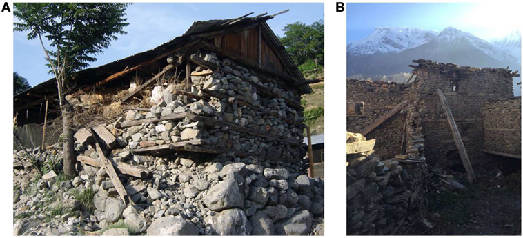
Figure 2. (A) Partially collapsed Bhatar house near Battagram in Pakistan (photo credit: Jitendra Bothera). (B) Out-of plane collapse mechanism of a wall and intervention with wooden posts in Nepal (photo credit: Tom Whity).
In the scientific literature, no specific studies are available regarding the structural behavior of Bhatar buildings, except from the studies by Langenbach (2003, 2009, 2015). The work by Langenbach (2015) provides a brief state of the art of the vernacular architecture in the Himalayas, providing the classification and the description of different construction types, as well as many interesting, even if only qualitative, considerations on the seismic behavior of such buildings. For instance, Langenbach underlines the fundamental role of timber lacing with these words: “Timber lacing and a strong tie between the timbers in the walls and the floors serve to restrain the walls from spreading and hold the building together while still allowing the system as a whole to be flexible.” Furthermore, he identifies the fundamental principle of the dry-stacked rubble stone masonry Bhatar technique in the dissipation of energy through friction (shear) between the various elements in the wall, such as stone with stone and stone with wood. Combined with the thickness and heavy weight of the walls, the capacity for dissipation of energy through friction is very high. Therefore, the use of mortars, especially cement mortar, is paradoxically not recommended. This makes the walls too stiff and reduces their capacity to absorb energy, as also stated by Gosain and Arya (1967).
Of course, advanced non-linear techniques, such as 3D discrete element method (Hart et al., 1988), finite element method (Bathe and Wilson, 1976) with solid brick elements with peculiar friction-interface on the horizontal layers (Macorini and Izzuddin, 2010), as well as applied element method (Meguro and Tagel-Din, 2000a,b) can be envisaged for the earthquake analysis of this kind of complex structures in which friction and dissipation play a fundamental role. However, at this first stage of the research, simple, even if rough, analytical calculations that allow to obtain the order of magnitude of the seismic activation multipliers might be preferred to non-linear methods whose results are extremely sensitive on the assumed parameters, and thus not fully reliable if not accompanied by sufficient experience.
An interesting collection of research papers on the seismic behavior of vernacular architecture is represented by the book of Correia et al. (2015). Part 1 and Part 2 of this book present traditional construction techniques in seismic areas that have been characterized, for a long time, by a large variety of structural solutions based on the combined use of brick or stone masonry, rammed earth, and timber elements. Examples can be found in the most seismic areas, such as Latin America (Chile, Perù, El Salvador), Nepal, Algeria, Turkey, some rural areas of Europe, as well as central and eastern Asian areas (China, Japan, Taiwan) where recent earthquake events have proved the adequacy or the vulnerability of some vernacular solutions. In the last decades, especially after catastrophic seismic events, scientific efforts have been invested by different authors worldwide in understanding the seismic performance of different typologies of vernacular architecture by means of on-field reconnaissance, experimental tests and numerical analyses (D’Ayala, 2004; Gutierrez, 2004; Torrealva et al., 2006; Sayın et al., 2013; Sorrentino et al., 2014; Varum et al., 2015; Gautam et al., 2016; Tonna et al., 2016; Aktaş, 2017; Barros et al., 2017). The main objectives are to investigate the seismic behavior of vernacular solutions in order to better individuate structural limits and primary factors affecting structural performance and to possibly indicate compatible reinforcement for seismic performance enhancing. Among these, it is worth citing the experimental campaign carried out by Ali et al. (2017). They performed dynamic shake table tests on three reduced-scale rubble-stone masonry models, one of them incorporating simple cost-effective features in the form of horizontal and vertical reinforced concrete (not timber) elements. The tests results highlight the importance of horizontal bands.
With the aim of understanding the actual structural response of dry-stacked rubble stone Bhatar constructions (detailed in Section “The Dry-Stacked Rubble Stone Masonry Bhatar Construction Technique”), the ongoing research discusses the following aspects: the identification of the material properties (see Materials Properties), the geometry of the wooden bands (see Timber Elements and Carpentry Connections), the selection of a representative case study (see The Case Study—One Room Building), the static analysis of a single Bhatar wall (see Static Analysis), the assumptions of the seismic analysis (see Seismic Analysis), the investigation of the in-plane seismic behavior of a single Bhatar wall (see In-Plane Seismic Analysis of a Bhatar Wall), and some initial considerations about the out-of-plane behavior of such buildings (see Preliminary Considerations on the Out-of-Plane Seismic Behavior of a Bhatar Wall).
The Dry-Stacked Rubble Stone Masonry Bhatar Construction Technique
The “Bhatar” technique that is examined in this paper consists of load-bearing walls made of common dry-stacked rubble stone masonry, held together by horizontal wooden bands disposed at several levels, spaced at intervals of around 60–130 cm (Figures 1A, and 3A–C). One of the most peculiar aspects of this dry-stacked Bhatar system is the absence of mortar and the use of timber to increase the confinement of the loose stone aggregate.
In more detail, a typical Bhatar building has an almost modular layout of load-bearing masonry piers, divided by small sized openings, and tied together by continuous timber ladders with modest vertical spacing. During stacking of the walls, it is important to provide proper bonding by adding sufficient through-stones over the full width of the wall, and to overlap longer stones in the corners. Dressed or semi-dressed stones provide better bonding patterns than random rubble or round river stones. Continuous vertical joints are to be avoided as much as possible. The bands resist out-of-plane bending and ensure stronger interconnection of the walls, thus further reducing the risk of vertical cracking at corners and T-sections, as well as delamination of the wall wythes. Furtherly, the bands reduce the risk of overturning of the relatively thick walls.
No precise building specifications have been developed until 2007, when a study was conducted by architect Schacher (2007) for the Swiss Agency for Development and Cooperation and the French Red Cross. This work provides an illustrated guide for craftsmen, in the Northwest Frontier province in Pakistan, and shows the steps for construction of a one-story building. It recommends maximum dimensions of around 3 m for height, 3.5 m for the sides of a square plan, and a minimum wall thickness of 0.45 m.
For the wooden reinforcements, it describes mainly two kinds of timber elements. First, “long members” parallel to the wall should be placed every 60 cm along the wall height. Second, transversal “short cross braces” with a maximum spacing of around 90 cm hold together the longitudinal long members, in order to compose the “horizontal wooden beam” or “horizontal band” (Figures 3A,B). Complex structures may be composed by coupling together simple units (Figure 3C).
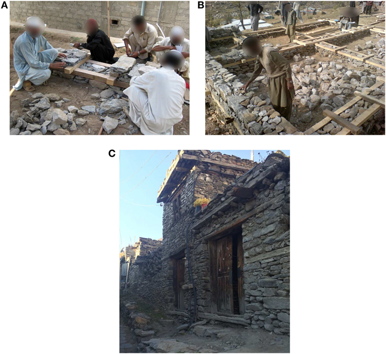
Figure 3. (A) Construction process of a single Bhatar wall (by courtesy of the French Red Cross). (B) Construction of a Bhatar building (by courtesy of the Swiss Agency for Development and Cooperation). (C) A typical Bhatar building (photo credit: Tom Whity).
Walls are generally built on shallow strip foundations, hand digging the soil up to a depth between 0.30 and 0.75 m, independently from soils characteristics (Hughes, 2005).
Materials Properties
The Bhatar technique adopts timber and stones as building materials. High variability in the material properties of the two constitutive materials may be encountered due to local availability and quality of timber essences (Shorea Robusta, Cedrus Deodara, Pinus Wallichiana, Populus Ciliata) and stone typologies (limestone, sandstone, granite, dolomite, quartzite). Thus, for the materials properties and the material interaction properties (on the stone–stone interface and on the stone–timber interface), reference is made to the most commonly used materials in the Himalayan regions: Shorea Robusta species for the timber and limestone for the stones. The interaction between these two materials being extremely important.
Timber: Shorea Robusta
Shorea Robusta, commonly known as Sal, is one of the typical timber species used in Nepal. The mechanical properties of Shorea Robusta have been specifically studied by many authors: Bellal Hossain and Abdul Awal (2012), Bhatt et al. (2015), and Sharma et al. (2008). Also reference information is available in the structural timber textbook by Giordano (1988).
In order to better quantify the mechanical properties of such timber within codified standards, data reported in literature have been compared with those given by European Standard UNI EN338:2009 (2009). With reference to the values of strength under bending and tension parallel to wood grain, Shorea Robusta may be classified into the D70 hardwood class. A summary of the main mechanical properties of D70 hardwood is listed in Table 1.
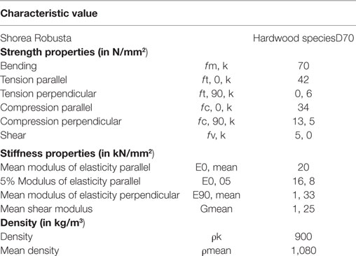
Table 1. Main mechanical properties of D70 hardwood.
Stone: Limestone
Typically, dolomite, sandstone, quartzite, and limestone are used in Nepal for aggregate in various construction works, road paving, and flooring (Kaphle, 2011). In the present study, limestone has been chosen as the particulate material for the rubble stone masonry.
The main mechanical properties of limestone may be expressed with reference to the following: (i) the rock material (at the scale of the particulate component) and (ii) the rock-fill (at the scale of an aggregate of many particulate components). In detail, the main parameters considered for characterizing limestone rock are as follows:
• the dry density;
• the rebound number (RN) with Schmidt hammer;
• the unconfined compressive strength (UCS).
Common values of such parameters were collected in the research work by Nazir et al. (2013) and are listed in Table 2.
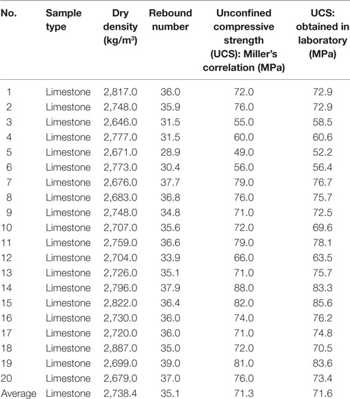
Table 2. Main mechanical characteristics for limestone [taken from Nazir et al. (2013)].
Stone–Stone Interface Properties
In a Bhatar wall, rocks of various sizes are fitted compactly together. A stone–stone interface is represented by the discontinuous contact surface between adjacent loose stones, characterized by rough joints. The effects of interlocking and friction between stones are responsible for the shear strength of the rock-fill under in-plane seismic actions. Thus, the structural behavior of the wall is highly dependent on the mechanical characterization of the interfaces between the stones.
In the scientific literature, and specifically in the field of Rock Mechanics, the mechanical proprieties of rock-fill have been studied by various authors (Patton, 1966; Leps, 1970; Barton, 2008), using different methods to describe the rock joints shear behavior from more idealized schemes (with simple linear functions) to more realistic schemes (with non-linear functions). The Barton’s model, which include the behavior of the rock discontinuities, has been considered for this paper.
In 1981, Barton and Kjaernsli (1981) developed an empirical model considering the aspect of rock-fill by using two comparative empirical parameters for JRC (Joint Roughness Coefficient) and JRS (Joint wall Compressive Strength), commonly simply referred to as R (Roughness) and S (Strength), respectively. Typically, R and S are obtained by means of in situ tests or estimated making use of abacuses (Barton, 2008).
On the one hand, Barton suggests that roughness R is estimated as a function of porosity (n%) and the origin of the rock-fill. In this study, considering the peculiarities of the Bhatar construction process, n = 20 and quarried rock origin have been assumed, thus leading to R≅ 10 (Figure 4A).
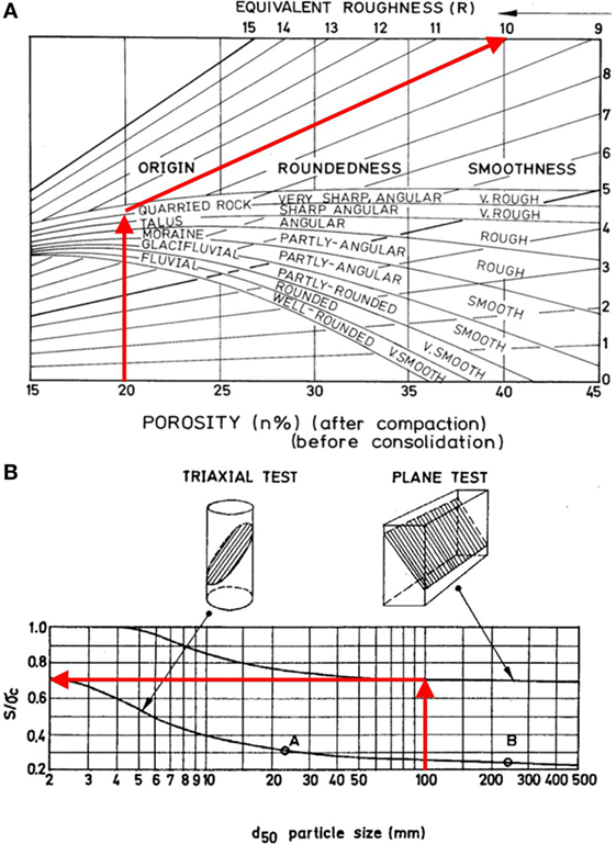
Figure 4. Abacuses for the identification of (A) the roughness R and (B) the strength S (taken from Barton, 2008).
On the other hand, Barton suggests that strength S is estimated as a function of the d50 particle size parameter and the kind of test conducted to measure the UCS of the rock sample tests (plane or triaxial testing). In this study, considering the peculiarities of the Bhatar construction process, d50 = 100 mm and “plane testing” have been assumed, thus leading to S = 0.7 σc (Figure 4B), where σc is the UCS.
Finally, Barton (2008) proposed the following empirical formula to assess the peak shear strength (τp) for rock-fill:
where σn is the applied normal stress and ϕr is the residual friction angle.
In this study, R ≅ 10. and S = 0.7. σc = 0.7. 71.3 MPa ≅ 50 MPa have been considered, using the mean value reported in Table 2 for the UCS (σc) of the limestone. As far as the value of the residual friction angle is concerned, Krsmanovic and Popovic (1966) proposed the value 13° for limestone with 6-mm clay layers and a range of values from 15° to 24° for limestone with 20-mm-thick Marlaceous joints. More recently, Melin (2012) discussed a number of direct shear tests on six rock types and found that the mean value of the residual friction angle decreases with increasing the ratio between the normal stress and the uniaxial compressive strength (similar to the peak friction angle), the mean value of the residual friction angle being slightly lower than the one of the peak friction angle. In this study, provided that unpredictable site construction conditions may lead to substantial differences in the rock-fill interbedded layers, and in order to obtain safe-side results, the lowest value 13° has been used. Thus, application of Eq. 1 to the case of the Bhatar wall leads to the following result:
Figure 5A represents the shear strength τp(σn) for the case under exam, according to Eq. 2. It can be observed that, for the limited stress range concerned, a simply linear relationship could be considered as first approximation (such as the Mohr–Coulomb’s friction law, where the term within the square brackets represents the friction angle φ, where cohesion is neglected). The results of a quick sensitivity analysis with respect to the three parameters of the Barton’s model are presented in Figures 5B,C,D. A variation of about ±20% has been taken for both R and S (even if for S it could be lower, provided that the coefficient of variation for the UCS values of Table 2 is around 14% and the ratio S/σc is almost constant, equal to 0.7 for large particle size). Making reference to the range of the ϕr values suggested by Krsmanovic and Popovic (1966), the values 13°, 18°, and 24° have been assumed. The model is basically not affected by the strength S of the stones, while, on average (over the common range of σn values), the variation in the shear strength due to a variation of +20% in the roughness R becomes equal to +25%. The choice of the residual friction angle ϕr plays an important role, since using 24° instead of 13° leads to an increase of about +50% in the shear strength. As later developed in Section “In-Plane Seismic Analysis of a Bhatar Wall,” the shear strength of the material directly affects the shear strength of the wall against sliding failure.
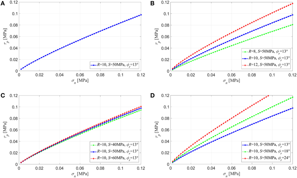
Figure 5. Shear strength for the Bhatar rock-fill according to Barton’s model (Eq. 1): (A) plot of Eq. 2 with the parameters considered in this study, (B) sensitivity analysis with respect to R, (C) sensitivity analysis with respect to S, and (D) sensitivity analysis with respect to ϕr.
Timber–Stone Interface Properties
A timber–stone interface is represented by the discontinuous contact surface between adjacent loose stones and horizontal timber elements.
In the present work, due to the fact that the timber–stone static friction coefficient (μt−s roughly equal to 0.4, according to Malhotra et al., 1994) is lower than the stone–stone static friction coefficient (μs−s around 0.9, according to Barton’s model of Eq. 2, as per the results reported in next Table 5) and in virtue of the limited stone–timber actual contact area (usually the contact is only punctual and discrete), for sake of safe-side conservative calculations, the contribution of the shear stresses between timber and stone to the in-plane shear strength of the rock-fill can be neglected (μt−s < μs−s).
Figure 6 shows the typical cross section of a Bhatar wall portion, including the horizontal band (long members). At level A–A, the blue arrows represent the normal stresses acting on a layer composed only by rubble stones. At level B–B, the blue arrows represent the normal stresses acting on the layer composed by the rubble stones and the timber long members. The normal stresses at levels A–A and B–B are equal:
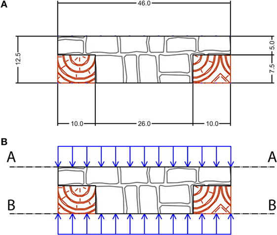
Figure 6. Vertical cross section of a typical Bhatar wall portion slice: (A) dimensions in [cm] and (B) levels A–A and B–B.
Assuming that μt−s < μs−s, the timber–stone contact area At−s can be neglected in the estimation of the shear strength at level B–B. Thus, the shear strength of level B–B is smaller than the shear strength of level A–A. An area reduction factor ξ may be introduced equal to the ratio of the stone–stone contact area As−s at level B–B to the total area A of the horizontal surface at level B–B. In this study, considering a wall thickness equal to 46 cm and a width of 10 cm for each one of the two timber long beams, the ratio (As−s/A) results equal to 0.57.
Timber Elements and Carpentry Connections
The Bhatar technique includes a number of horizontal timber reinforcements with specific functions, which are incorporated into the rubble stone wall masonry. These members confine the wall structure and provide it with tension strength. The “horizontal wooden beams,” sometimes also referred to as “horizontal bands” or “ladders,” are composed of two parallel longitudinal “long members” over the length of the wall, connected to each other with transversal “short cross braces” over the width of the wall.
The bands are placed at roughly 60 cm interval in height and fulfill different roles such as the following:
• foundation beams, continuous;
• wall beams, semi-continuous due to disruption of door openings;
• lintel beams, which continuously cross over the level of doors and windows;
• top beams, continuous, also called roof beams as they are used to connect the roof to the wall (Figure 7).
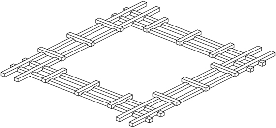
Figure 7. The four horizontal wooden beams at the roof level.
To analyze the stresses on the timber elements, the areas of the significant cross sections of both the long members and the short cross braces have been first identified in Figures 8A,B, then computed and reported in Table 3.
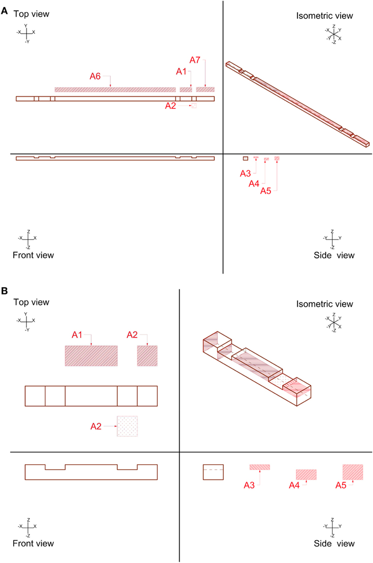
Figure 8. Typical dimensions of (A) the “long members” and (B) the “short cross braces.”
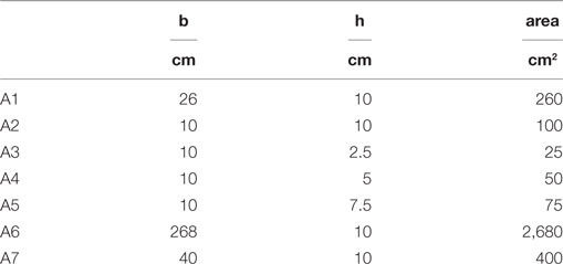
Table 3. Areas of the significant cross sections of the “long members” and the “short cross braces.”
The Case Study—One Room Building
According to the guidelines given by Schacher (2007), a basic one-room building unit has been defined, which is characterized by the following details (Figure 9):
• foundation made of stones,
• seismic horizontal bands made of wood,
• square plan dimensions L = 3.6 m and W = 3.6 m,
• height H = 3.1 m,
• 1 door characterized by width = 0.9 m and height = 2.4 m,
• 2 windows characterized by width = 0.9 m and height = 0.6 m.
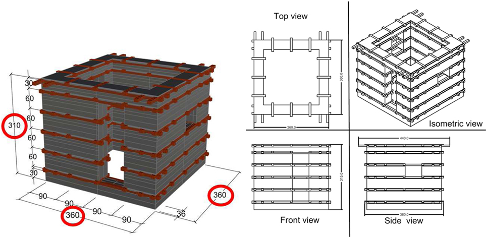
Figure 9. Sketch and dimensions of the considered Bhatar building unit.
The Bhatar building is studied making reference to four single walls (the only one without openings is detailed in Figure 10).
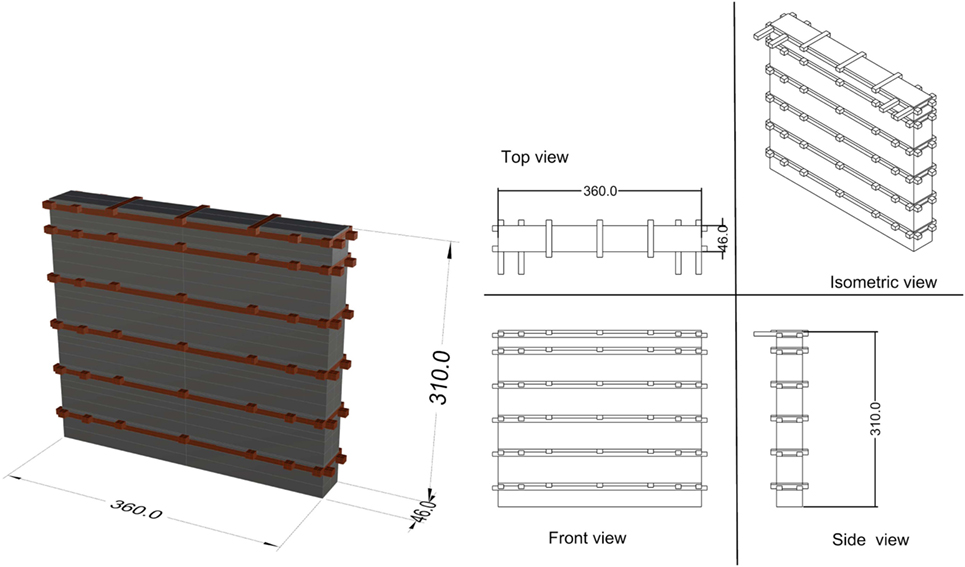
Figure 10. Sketch and dimensions of the single Bhatar wall without openings.
The roof has been considered as flat heavy roof with earth cover, which is composed as follows from the bottom up (Figure 11):
• Timber roof beams,
• Roof joists 10 cm height,
• Planks 3 cm thick,
• Ring of flat stones 10-cm thick,
• Layer of twigs 5-cm thick,
• Layer of earth 20-cm thick.
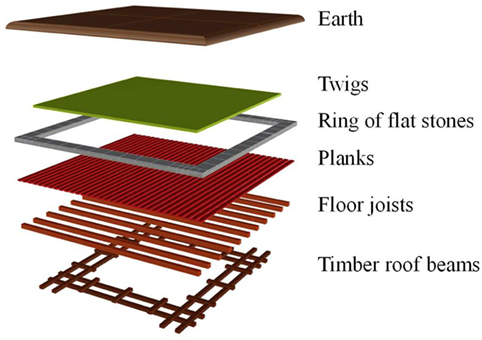
Figure 11. Flat heavy earthen roof.
Static Analysis
The stress levels acting on each horizontal layer of the Bhatar wall are computed by taking into account the weight of the roof and the self-weight of the wall.
The static analysis has been conducted with reference to a 1.20-m-wide vertical strip portion of the Bhatar wall (characterized by dimensions: 1.20 m × 0.46 m × 3.00 m), as represented in Figure 12.
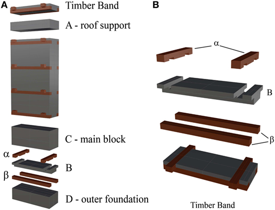
Figure 12. (A) The 1.2 m wide vertical strip portion of the Bhatar wall. (B) Details of the wall around the horizontal wooden band.
Figure 13 identifies the levels at which the stresses have been computed. They correspond to the critical stone–timber contact interfaces immediately below each horizontal wooden band, and to the ground level.
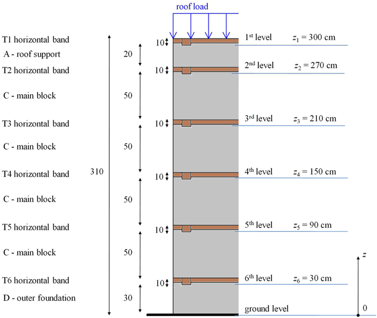
Figure 13. Levels under consideration for the estimation of the normal stresses acting on the wall.
The mean value of the normal stress acting at the j-th level (j = 1, …, 6, see Figure 13) just below an horizontal wooden band is given by
where A is the horizontal area at each level, Wroof is the amount of roof load acting on the considered wall, Wlayer,i is the self-weight of each layer, while Wj is the total weight (i.e., the axial force) acting at the j-th level.
These weights have been computed by simply multiplying the volume of each elementary part, represented in Figure 12, with its corresponding unit weight, and by consistently summing each contribution, as detailed in Table 4. In the present study, with reference to the 1.2 m wide vertical wall portion, A = 1.2 m × 0.46 m = 0.55 m2. Also, considering the specific weight of the stones γstone = 26.86 kN/m3 and a void ratio equal to 0.26, the specific weight of the rubble stones has been taken equal to γstone = 19.88 kN/m3. For the timber elements, γtimber = 9.00 kN/m3 has been assumed. The heavy roof described in Figure 11 is sustained by the floor joists, which are supported by two opposite walls. Therefore, the total weight of the roof (around 102 kN) is only applied to two (each one sustaining around 51 kN) out of the four 3.6-m-long walls, i.e., only to the ones that are perpendicular to the floor joists. Consequently, the considered 1.2-m-wide vertical stripe portion takes around 17 kN.
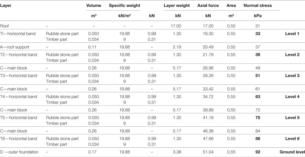
Table 4. Details of static analysis and normal stresses at different heights: the bold font highlights the selected levels, identified in Figure 13, to which reference is made in following Table 5.
Table 4 presents the mean values of the normal stress acting at each level. In computing the normal stress acting at the roof level, Wroof is considered as uniformly distributed along the 1.2 m length of the considered wall portion. At each level, the limited stress value does not represent an issue for limestone strength which is around 70,000 kPa, according to Nazir et al. (2013). At the ground interface, the stress level is around 92 kPa. Even if quite larger, this value can be considered acceptable for common soils, but settlement issues should be taken into account. On-field data reports recognized the frequent presence of differential settlements affecting Bhatar buildings (Hughes, 2005). However, Bhatar walls could withstand moderate differential settlements thanks to their flexibility.
Seismic Analysis
The effects of an earthquake ground motion on a structure are basically associated with inertial forces which are proportional to the mass of the structure and to the peak ground acceleration (PGA) impressed at the base. In this preliminary investigation on the seismic behavior of Bhatar systems, the seismic analyses are carried out under the following assumptions:
1. The effect of the earthquake ground motion is represented by a uniform vertical distribution of horizontal inertia forces, proportional to the PGA. This is due to the low-rise configuration of the building, and the stockiness and high lateral stiffness of the wall, which lead to negligible structural amplification. Consequently, the horizontal seismic shear force acting at the j-th interface of the wall, Vj, is given by
where g is the gravity acceleration and α = PGA/g represents the seismic activation load multiplier.
2. No vertical component of the earthquake ground motion is considered.
3. No global cellular behavior of the building unit is considered. The study is conducted with reference to the single 3.6-m-length wall only.
In-plane seismic capacity of the Bhatar wall is quantitatively evaluated in Section “In-Plane Seismic Analysis of a Bhatar Wall,” while only preliminary observations on the out-of-plane seismic capacity are made in Section “Preliminary Considerations on the Out-of-Plane Seismic Behavior of a Bhatar Wall.”
In-Plane Seismic Analysis of a Bhatar Wall
In this section, the in-plane seismic behavior of a single Bhatar wall is investigated, in order to identify the value of the horizontal acceleration which triggers in-plane failure mechanisms.
Only the failure mechanism associated with the horizontal sliding between adjacent rubble stones layers can be envisaged. As a matter of fact, the diagonal cracking failure, typical of masonry walls, does not straightforwardly apply to this kind of structures, since the wall shows up in “already cracked conditions” due to its constructive typology. This effectiveness has been seen in recent major earthquakes in Turkey, India, and Pakistan (Langenbach, 2003; Rai and Murty, 2005). Furthermore, the failure mechanism which involves a combined action of axial force and bending moment at the base of the wall is not significant for stocky elements.
The in-plane seismic analysis is based on the application of Barton’s empirical model for rock-fill presented in Section “Stone–Stone Interface Properties.” The Barton’s model provides the shear strength as a function of the normal stress and other rock-fill parameters. This non-linear model permits to estimate the value of the friction coefficient which develops at each layer, due to the vertical load and the self-weight. The normal stresses have been taken from the static analysis. These friction coefficients are then used to calculate, at each level, the shear resistance of the wall to the horizontal forces due to the seismic event. Table 5 reports the friction coefficients at each level. Only the levels that correspond to the critical stone–timber contact interfaces immediately below each horizontal wooden band have been considered.
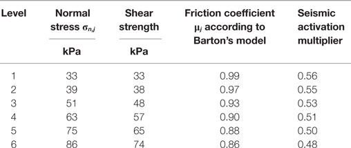
Table 5. Normal stresses, shear strengths, friction coefficients at the levels just below the horizontal wooden beams, and corresponding seismic activation multipliers for in-plane sliding mechanisms.
Horizontal sliding failure occurs when, at the generic j-th layer, the seismic shear force (Vj) is larger than the shear strength (Rsliding,j) of the wall. The shear strength against sliding failure at the j-th level, Rsliding,j, depends on the friction coefficient μj and the vertical compression normal stress σn,j at the j-th level
The failure is triggered if Vj is larger than the corresponding Rsliding,j. Thus, the value of α that triggers the horizontal sliding of two adjacent layers can be obtained by imposing:
which leads to
Thus, the acceleration which activates the sliding failure depends on the interface friction between adjacent layers and, with specific reference to the critical layers identified as the ones just below the horizontal wooden beams for which the timber–stone interface friction is neglected, also on the As–s/A ratio given in Eq. 4. If vertical (steel or timber) connectors or rock elements are inserted in such a way they provide a cutting strength along this interface, the friction coefficient will increase, as well as the sliding strength of the wall.
Table 5 also reports the seismic activation multipliers at each level. α values around 0.5 have been obtained for the lower levels. Despite all the strong assumptions, this gives a robust indication that in-plane behavior appears not to be a seismic issue for Bhatar buildings. These simple calculations are capable of justifying the experimental pieces of evidence of Bhatar structures capable of sustaining PGA values around 0.5 g, as witnessed recently in Nepal. To account for possible discrepancies relevant to all uncertainties, especially the material properties, the strong assumptions, and the rough modeling, for design purposes a global safety factor should be introduced at least equal to 2.
Just to give some reference acceleration values in Nepal, the 500-year return period PGAs are in the range of 0.22–0.50 g, as per the results of the hazard analysis developed by Chaulagain et al. (2015). These values are consistent with the prescriptions of the Nepal National Building Code, NBC 105 (1994). In fact, it prescribes, for structures of minimal ductility including masonry bearing wall structures, other than monumental buildings and essential or critical safety facilities, a design horizontal acceleration around 0.32 g. Also, the NBC105:1994 states that, in general, the effects of the vertical component of seismic motion need not be considered in the design of a common structure. Nonetheless, where consideration of vertical seismic forces is required, it prescribes that the design vertical acceleration shall be taken as one half of the horizontal one. Thus, vertical accelerations can be estimated to be in the range of 0.11–0.25 g. These values, even considering structural amplification factors in the vertical direction around 2.5 and 3, are not likely to cause uplifting of the structure and the annihilating of normal stress between stones. In this respect, it should be pointed out that, in this study, shear strength has been evaluated on the basis of friction. However, vertical ground motion can be capable of reducing the normal stress between two adjacent layers and thus the shear strength. For this reason, the addition of vertical timber beams can be envisaged to connect the cross braces along a vertical line, to avoid vertical detachment of the horizontal layers in earthquake conditions (see Figure 14).
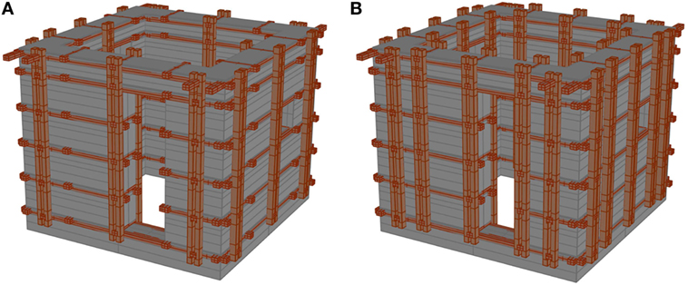
Figure 14. Sketches of the Bhatar building equipped with additional vertical timber beams: (A) thrifty solution and (B) optimal solution.
Preliminary Considerations on the Out-of-Plane Seismic Behavior of a Bhatar Wall
Out-of-plane failure mechanisms may occur due to overturning behavior with a rigid response of the wall (Figure 15A) or due to a bending behavior with a flexible response of the wall (Figure 15C).
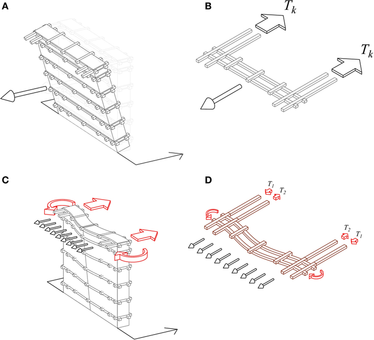
Figure 15. (A) Overturning behavior with a rigid response of the wall. (B) Tie action provided by the two horizontal bands at the k-th level. (C) Bending behavior with a flexible response of the wall. (D) Horizontal wooden beams acting as bond beams at each level.
Both mechanisms are still under investigation. On the one hand, the overturning with a rigid response of the wall (Figure 15A) is counteracted by the tie actions provided by the horizontal bands (Figure 15B), with the flat heavy earth roof acting as a deformable slab. On the other hand, the bending behavior with flexible response of the wall (Figure 15C) is investigated with the heavy roof being a deformable slab, and with the embedded timber elements considered as bond beams providing flexural stiffness and strength to the wall (Figure 15D).
As far as the overturning behavior with a rigid response of the wall is concerned, kinematic analysis can be easily performed and is here briefly presented. The 3.6-m-long wall is considered as composed of horizontal rigid blocks overturning around possible ideal horizontal cylindrical hinges at each wooden band level (the failure mechanism around the horizontal hinge at the ground level is displayed in Figure 15A). The value of the seismic acceleration multiplier α that triggers this out-of-plane mechanism at the generic j-th level can be obtained by imposing the rotational equilibrium
The destabilizing and stabilizing moments Mdest,j and Mst,j are evaluated around the horizontal cylindrical hinge formed at the j-th level and are related to the seismic horizontal inertial forces corresponding to the roof and the wall, and to the self-weight of the structure (roof + wall) and the tie actions Tk of the horizontal bands above the hinge formation level, respectively.
The destabilizing overturning moment is
and the stabilizing moment is
where Wrοt,j is the weight of the wall portion rotating above the j-th horizontal band, zj represents the height of the j-th horizontal band level, and twall is the thickness of the wall (0.46 m). 2Tk represents the total tie action provided by the two horizontal bands at the k-th level at both sides, counteracting the detachment mechanism of the considered wall portion from the two orthogonal walls which work as lateral-resisting elements with in-plane actions (Figure 15B).
Provided that the axial strength of the horizontal band (Nt,0,Rd) is far larger than the horizontal friction force at the k-th timber–stone interface level (Ffr.k) triggered by the relative motion between the two longitudinal “long members” and the stone blocks of the orthogonal walls, the maximum tie action Tk is governed by friction:
where μt−s = 0.40, At−s = 3.6 m (2·0.10)m = 0.72 m2 and σn,k is the normal stress at the k-th level (see Table 4). Eq. 11 leads to the following α load multiplier:
Table 6 reports the values of the seismic acceleration multiplier α as function of the position (level) of the horizontal cylindrical hinge for the rigid response out-of-plane mechanism. The lowest value of α is around 0.74 for the wall portion rotating around an horizontal cylindrical hinge located at zj = 2.10 m (j = 3) and, thus, larger than the one (around 0.50) activating the sliding mechanisms for the in-plane analysis. Thus, the results seem to suggest that, due to the tie action offered by the horizontal wooden bands, in-plane behavior is more dangerous than out-of-plane behavior. However, rigid response of the wall is a strong assumption that allows for easy calculations, but flexible response of the wall should also and still be analyzed. In any case, local sliding mechanisms and possible consequent detachment of stones in the main blocks (see Figures 12 and 13) may also occur in the wall as subjected to orthogonal seismic action. In this respect, in addition to ensure friction also in the case of vertical ground motions, the introduction of additional vertical timber beams according to Figure 14 would be useful (i) to reduce the local sliding of stones in the direction perpendicular to the wall (by simply acting as distributed vertical physical restraints), (ii) to enhance the tie action up to values referable to the axial strength of the long members of the horizontal wooden bands (by acting as external end anchorages, such as those used to fix the tie-rods in the strengthening interventions on masonry structures), and (iii) to involve a global cellular response of the three-dimensional building.
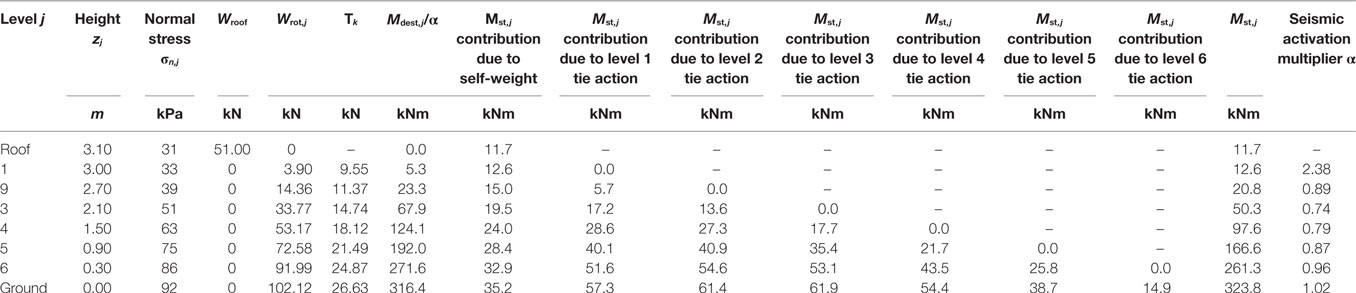
Table 6. Values of α for various locations of the horizontal cylindrical hinges for the rigid response out-of-plane mechanism.
Conclusion
Bhatar is a vernacular construction technique of the Himalayan regions which is grounded upon the “timber lacing” or “timber reinforcement masonry” concept, i.e., the combination of dry-stacked loose stones with timber beams to increase the wall confinement. The timber provides wall reinforcement and strong resistance against tension and bending, thereby complementing the compression properties of the rubble stone masonry. Moreover, this technique makes it easier to build straight-sided walls, and it allows to create strong corner joints due to long members that provide tensile/bending resistance to out-of-plane wall movements.
This work reports a preliminary analytical study aimed at giving a first insight into the static and seismic behavior of a small one-room Bhatar building, characterized by a 3.6 m × 3.6 m square plan, of 3.1 m height, and a flat heavy roof with earth cover.
First, a research has been conducted about the mechanical properties of the construction materials commonly used in Nepal regions, such as Shorea Robusta wood and limestone rocks. The Barton’s model has been applied to characterize the shear strength of the rubble stone layers in the wall.
Then, static analysis has been developed by sub-dividing each Bhatar wall into a number of layers, for which the volume and the weight have been precisely computed. The normal stress at the ground interface is around 92 kPa, which, even if quite larger, can be considered acceptable for common soils, since Bhatar walls can withstand moderate differential settlements thanks to their flexibility.
With respect to earthquake, the Bhatar technique can absorb and resist wall cracking and distortion mechanisms. This effectiveness has been seen in recent major earthquakes, such as in Turkey, India, and Pakistan (Kashmir). For the Bhatar system, the only possible in-plane seismic failure mechanism is the horizontal sliding between the stones. The acceleration which activates this mechanism depends on the interface friction between adjacent layers, and the critical layers are identified as those just below the horizontal wooden beams for which the timber–stone interface friction can be neglected with respect to the stone–stone interface friction. Under the assumption of no vertical ground motion (i.e., friction forces are guaranteed), the seismic activation acceleration values are found to be around 0.5 g.
Although this study should be considered as a starting point, the simple analytical developments presented in this manuscript, as well as the ongoing research of the out-of-plane seismic analysis, are capable of justifying the experimental evidences of Bhatar structures being able to sustain PGA values around 0.5 g, as observed in Nepal in 2015. Moreover, some rules of thumb have been envisaged to improve the shear strength (insertion of vertical steel or timber connectors, or including rock elements which can provide a cutting strength along the critical interfaces) and to ensure friction also in the case of significant vertical component of the earthquake ground motion (introduction of vertical timber beams to connect the cross braces along a vertical line). An analytical study devoted to the out-of-plane seismic behavior of the Bhatar technique will be presented in a forthcoming paper.
Finally, it is worth pointing out that the results are based on the assumptions taken by several authors and have not been verified with experimental tests. Also, further numerical research as well as shaking-table tests are necessary in order to obtain confirmation of the obtained results and to explore the effectiveness of the cellular behavior.
Author Contributions
This work derives from the main results of the Master graduation thesis of RC, who performed all initial analyses on Bhatar structures. LP and SS supervised both the thesis and this work, identifying the general research lines. They suggested the analytical approach and performed the final analyses. SS also drew the conclusions. MS was the inspiring person who solicited this work. On the basis of his field experience in developing countries, he provided useful information about the materials, he checked the nomenclature and revised both the literature review and the whole manuscript.
Conflict of Interest Statement
The authors declare that the research was conducted in the absence of any commercial or financial relationships that could be construed as a potential conflict of interest.
References
Aktaş, Y. D. (2017). Seismic resistance of traditional timber-frame Hımış structures in Turkey: a brief overview. Int. Wood Prod. J. 8, 21–28. doi: 10.1080/20426445.2016.1273683
Ali, Q., Ahmad, N., Ashraf, M., Rashid, M., and Schacher, T. (2017). Shake table tests on single-story Dhajji Dewari traditional buildings. Int. J. Arch. Heritage 11, 1046–1059. doi:10.1080/15583058.2017.1338789
Barros, R., Rodrigues, H., Varum, H., Costa, A., and Correia, M. (2017). Seismic analysis of a Portuguese vernacular building. J. Arch. Eng. 24, 05017010. doi:10.1061/(ASCE)AE.1943-5568.0000258
Barton, N. (2008). “Shear strength of rockfill, interfaces and rock joints, and their points of contact in rock dump design,” in Rock Dumps 2008 (Perth: Australian Centre for Geomechanics). Available at: http://www.nickbarton.com/Downloads_new/2008.Barton-ShearStrengthRockfill-InterfacesRockJoints-TheirPointsContactRockDumpDesign.zip
Barton, N., and Kjaernsli, B. (1981). Shear strength of rockfill. J. Geotech. Eng. Div. 107, 873–891.
Bathe, K. J., and Wilson, E. L. (1976). Numerical Methods in Finite Element Analysis. Englewood Cliffs, NJ: Prentice Hall.
Bellal Hossain, M., and Abdul Awal, A. S. M. (2012). Mechanical properties and durability of some selected timber species. Malays. J. Civ. Eng. 24, 67–84.
Bhatt, S., Dutt, B., Meena, R. K., and Ahmad, T. (2015). Studies on tensile strength property of commercial timber species of Solan District, Himachal Pradesh. Int. J. Farm Sci. 5, 119–123.
Chaulagain, H., Rodrigues, H., Silva, V., Spacone, E., and Varum, H. (2015). Seismic risk assessment and hazard mapping in Nepal. Nat. Hazards 78:583–602. doi:10.1007/s11069-015-1734-6
Correia, M. R., Lourenço, P. B., and Varum, H. (eds) (2015). Seismic Retrofitting: Learning from Vernacular Architecture. London: CRC Press/Balkema, Taylor and Francis Group.
D’Ayala, D. (2004). “Correlation of fragility curves for vernacular building types: houses in Lalitpur, Nepal and in Istanbul, Turkey,” in Proceedings of the 13th World Conference of Earthquake Engineering (Vancouver, BC). Paper No. 485.
Dowling, D., Pere, P., and Perrault, P. (2007). Building Back Better – Bhattar. Background and Rationale. Pakistan: UN-HABITAT.
European Standard UNI EN 338:2009. (2009). Structural Timber – Strength Classes. Brussels: European Committee for Standardization (CEN).
Gautam, D., Prajapati, J., Paterno, K. V., Bhetwal, K. K., and Neupane, P. (2016). Disaster resilient vernacular housing technology in Nepal. Geoenviron. Disasters 3, 1. doi:10.1186/s40677-016-0036-y
Gosain, N., and Arya, A. S. (1967). “A report on Anantnag earthquake of February 20, 1967,” in Bulletin of the Indian Society of Earthquake Technology, Vol. 3.
Gutierrez, J. (2004). “Notes on the seismic adequacy of vernacular buildings,” in Proceedings of the Thirteenth World Conference on Earthquake Engineering, (Vancouver, BC), Paper No. 5011.
Hart, R., Cundall, P. A., and Lemos, J. (1988). Formulation of a three-dimensional distinct element model-part II. Mechanical calculations for motion and interaction of a system composed of many polyhedral blocks. Int. J. Rock Mech. Min. Sci. 25, 117–125. doi:10.1016/0148-9062(88)92294-2
Hughes, R. (2005). “Vernacular architecture and construction techniques in the Karakoram,” in Karakoram: Hidden Treasures in the Northern Areas of Pakistan, ed. S. Bianca (Torino: The Aga Khan Trust for Culture), 99–132.
Kaphle, K. P. (2011). Minerals Resources of Nepal and Their Present Status. Available at: http://ngs.org.np/geodetail/4
Krsmanovic, D., and Popovic, M. (1966). “Large scale field tests of the shear strength of limestone,” in Proceedings of 1st Congress of International Society of Rock Mechanics, Vol. 1 (Lisbon), 773–779.
Langenbach, R. (2003). Survivors Amongst the Rubble: Traditional Timber-Laced Masonry Buildings that Survived the Great 1999 Earthquakes in Turkey and the 2001 Earthquake in India, While Modern Buildings Fell. Madrid: International Congress on Construction History.
Langenbach, R. (2009). Don’t Tear It Down! Preserving the Earthquake Resistant Vernacular Architecture of Kashmir – Text and Photographs by Randolph Langenbach. India: Vernacular Architecture of Kashmir – United Nations Educational, Scientific and Cultural Organization (UNESCO).
Langenbach, R. (2015). “The earthquake resistant vernacular architecture in the Himalayas,” in Seismic Retrofitting: Learning from Vernacular Architecture (London: Taylor & Francis Group), 83–92.
Leps, T. M. (1970). Review of the shearing strength of rockfill. J. Soil Mech. Found. Div. 96, 1159–1170.
Macorini, L., and Izzuddin, B. A. (2010). A non-linear interface element for 3D mesoscale analysis of brick-masonry structures. Int. J. Numer. Methods Eng. 85, 1584–1608. doi:10.1002/nme.3046
Malhotra, M. M., Subramanian, R., Gahlot, P. S., and Rathore, B. S. (1994). Textbook in Applied Mechanics. New Delhi, India: New Age International (P) Ltd.
Meguro, K., and Tagel-Din, H. (2000a). Applied element method for structural analysis: theory and application for linear materials. Struct. Eng. 17, 21s–35s.
Meguro, K., and Tagel-Din, M. (2000b). Applied element method for dynamic large deformation analysis of structures. Struct. Eng. 17, 215s–224s.
Melin, H. (2012). Controlling Parameters for Normal and Shear Behaviour of Rock Fractures – A Study of Direct Shear Test Data from SKB. Master of Science Thesis, Stockholm, Sweden. Available at: kth.diva-portal.org/smash/get/diva2:524789/FULLTEXT01.pdf
Nazir, R., Momeni, E., Armaghani, D. J., and Amin, M. F. M. (2013). Prediction of unconfined compressive strength of limestone rock samples using L-type Schmidt hammer. Electronic Journal of Geotechnical Engineering EJGE 18, 1767–1775.
Nepal National Building Code, NBC 105: 1994. (1994). Seismic Design of Buildings in Nepal. Babar Mahal, Kathmandu, Nepal: Government of Nepal, Ministry of Physical Planning and Works, Department of Urban Development and Building Construction.
Patton, F. D. (1966). “Multiple modes of shear failure in rock,” in Proceedings of 1st Congress of International Society of Rock Mechanics, Vol. 1 (Lisbon), 509–513.
Rai, D. C., and Murty, C. V. R. (2005). Preliminary Report on the 2005 North Kashmir Earthquake of October 8, 2005. Kanpur, Indian Institute of Technology. Available at: https://www.eeri.org/lfe/pdf/kashmir_eeri_1st_report.pdf
Sayın, E., Yön, B., Calayır, Y., and Karaton, M. (2013). Failures of masonry and adobe buildings during the June 23, 2011 Maden-(Elazığ) earthquake in Turkey. Eng. Fail. Anal. 34, 779–791. doi:10.1016/j.engfailanal.2012.10.016
Schacher, T. (2007). Bhatar Construction, Timber Reinforced Masonry; An Illustrated Guide for Craftsmen. Mansehra: NWFP.
Sharma, R., Sinha, R., Acharya, P., Mishnaevsky, L. Jr., and Freere, P. (2008). “Comparison of test results of various available Nepalese timbers for small wind turbine applications,” in Proceedings of 3rd International Conference – Asia Pacific Region (ISES-AP-08) and 46th ANZSES Conference (Sydney, Australia).
Sorrentino, L., Liberatore, L., Liberatore, D., and Masiani, R. (2014). The behaviour of vernacular buildings in the 2012 Emilia earthquakes. Bull. Earthq. Eng. 12, 2367–2382. doi:10.1007/s10518-013-9455-2
Tonna, S., Sumini, V., Chesi, C., Chillè, F., Prajapati, S., and Sorrentino, L. (2016). “Seismic protection and preservation of the Newari architecture in Nepal,” in 10th Int. Conf. on Structural Analysis of Historical Constructions (SAHC 2016) Leuven, eds K. Van Balen, and E. Verstrynge (London: CRC Press/Balkema, Taylor and Francis Group), 1613–1620.
Torrealva, D., Neumann, J. V., and Blondet, M. (2006). “Earthquake resistant design criteria and testing of adobe buildings at Pontificia Universidad Catòlica del Peru,” in Proceedings of the Getty Seismic Adobe Project 2006 Colloquium (Los Angeles, CA: Getty Conservation Institute), 3–10.
Varum, H., Rodrigues, H., Lourenço, P. B., and Vasconcelos, G. (2015). “Seismic behaviour of vernacular architecture,” in Seismic Retrofitting: Learning from Vernacular Architecture, 151. Available at: https://repositorium.sdum.uminho.pt/handle/1822/38134
Keywords: Bhatar, vernacular construction technique, rock-fill material, horizontal wooden bands, static analysis, seismic analysis
Citation: Carabbio R, Pieraccini L, Silvestri S and Schildkamp M (2018) How Can Vernacular Construction Techniques Sustain Earthquakes: The Case of the Bhatar Buildings. Front. Built Environ. 4:18. doi: 10.3389/fbuil.2018.00018
Received: 01 December 2017; Accepted: 09 March 2018;
Published: 12 April 2018
Edited by:
Luigi Di Sarno, University of Sannio, ItalyReviewed by:
Roberto Nascimbene, European Centre for Training and Research in Earthquake Engineering, ItalyEmanuele Brunesi, European Centre for Training and Research in Earthquake Engineering, Italy
Hugo Rodrigues, Polytechnic Institute of Leiria, Portugal
Copyright: © 2018 Carabbio, Pieraccini, Silvestri and Schildkamp. This is an open-access article distributed under the terms of the Creative Commons Attribution License (CC BY). The use, distribution or reproduction in other forums is permitted, provided the original author(s) and the copyright owner are credited and that the original publication in this journal is cited, in accordance with accepted academic practice. No use, distribution or reproduction is permitted which does not comply with these terms.
*Correspondence: Stefano Silvestri, c3RlZmFuby5zaWx2ZXN0cmlAdW5pYm8uaXQ=