 Daniel Orfeo
 Dylan Burns
 Henry Mitchell
 Dryver R. Huston
- School of Engineering, University of Vermont, Burlington, VT, United States
This study reports on the theory of operation, design principles, and results from laboratory and field tests of a magnetic telemetry system for communication with underground infrastructure sensors using rotating permanent magnets as the sources and compact magnetometers as the receivers. Many cities seek ways to monitor underground water pipes with centrally managed Internet of Things (IoT) systems. This requires the development of numerous reliable low-cost wireless sensors, such as moisture sensors and flow meters, which can transmit information from subterranean pipes to surface-mounted receivers. Traditional megahertz radio communication systems are often unable to penetrate through multiple feet of earthen and manmade materials and have impractically large energy requirements which preclude the use of long-life batteries, require complex (and expensive) built-in energy harvesting systems, or long leads that run antennas near to the surface. Low-power magnetic signaling systems do not suffer from this drawback: low-frequency electromagnetic waves readily penetrate through several feet of earth and water. Traditional magnetic telemetry systems that use energy-inefficient large induction coils and antennas as sources and receivers are not practical for underground IoT-type sensing applications. However, rotating a permanent magnet creates a completely reversing oscillating magnetic field. The recent proliferation of strong rare-earth permanent magnets and high-sensitivity magnetometers enables alternative magnetic telemetry system concepts with significantly more compact formats and lower energy consumption. The system used in this study represents a novel combination of megahertz radio and magnetic signaling techniques for the purposes of underground infrastructure monitoring. In this study, two subterranean infrastructure sensors exploit this phenomenon to transmit information to an aboveground radio-networked magnetometer receiver. A flow meter uses a propeller to directly rotate a diametrically magnetized neodymium magnet. A moisture sensor rotates a magnet with a low-power electric motor. Laboratory performance and field tests establish the capabilities of magnetic telemetry for IoT-linked leak-detection sensors. Remote datalogging with encryption demonstrates the viability of integrating sensors and surface receivers into a LoRa wireless IoT network.
Introduction
Buried infrastructure, such as water and sewer pipes, are often located in congested urban areas, in unknown locations, and in unknown condition. The American Society of Civil Engineers (ASCE) gives drinking water and wastewater infrastructure in the United States grades of D and D+, respectively (ASCE, 2017). Leak detection is a particularly urgent problem, with some municipalities reporting non-revenue water loss up to 50% (Lambert, 2002; Goulet and Smith, 2013; Adedeji et al., 2017; Huston and Xia, 2017).
Leak detection has three primary goals: quantifying amount of water loss, identification of leak location, and the development of leakage control models (Puust et al., 2010). These goals are achieved in several ways: on-site pipe inspection, statistical modeling of past known failures, modeling of physical pipe/soil attributes, and evaluation of the impacts of specific pipe failure modes (Liu and Kleiner, 2013). Non-intrusive non-destructive testing is especially important so as to avoid water shutoffs which are disruptive to customers, and can cause disturbance of internal pipe tuberculation (Rajani and Kleiner, 2004). Methods of on-site pipe inspection include acoustic detection (Khulief et al., 2012), laser-scanning of pipe interiors, magnetic flux leakage measurements, remote field eddy current detection, broadband electromagnetic sensing, pulsed eddy current testing, (Liu and Kleiner, 2013), and ground penetrating radar (Huston et al., 2017). Not all inspection techniques work for all pipe materials and diameters (Rajani and Kleiner, 2004), however, which complicates the inspection process. Furthermore, detection sensitivity challenges are omnipresent. For example, water leaks at pipe joints and fittings often have flow rates too low to be identified with acoustic detection methods (Lambert, 2002).
A strategy to improve underground utility operations is to use multiple sensors and the IoT to determine the state of infrastructure, including flow levels, leak detection, and unauthorized usage. An example of underground infrastructure sensor networking is in the city of South Bend, Indiana, USA, with CSOnet, which provides real-time control of storm water infrastructure for combined sewer overflow abatement (Montestruque and Ruggaber, 2007). A challenge is that communication with sensors in and around subterranean water utilities is often obstructed by asphalt, rebar, concrete, manhole covers, in addition to several feet of earth and soil. Low-power megahertz radio systems, such as LoRa, do not transmit well through these obstacles (Montestruque and Lemmon, 2008). As the 900 MHz radio used in the CSOnet system was unable to broadcast out of the South Bend sewer system, wireless networking required replacing iron and steel manhole covers with customized fiberglass alternatives, which contained embedded radio antennas (Montestruque and Lemmon, 2008).
The penetrating ability of magnetic signaling makes it well-suited for direct communication with sensors used for monitoring underground utilities, without the need for modifications to existing infrastructure such as manhole covers. Most materials, including earth and sea water, do not interact with magnetic fields that oscillate below 3,000 Hz, making magnetic signaling compatible with the demands of low-bitrate through-earth communication with buried infrastructure.
Large electric induction coils, or massive antennas that resonate with the desired transmission frequency, are the traditional method of generating and receiving low-frequency magnetic fields. The physical principle is the linear motion of charged particles, i.e., electrons, through conductors creates and receives magnetic fields. The wavelengths of low frequency electromagnetic waves range from tens to thousands of kilometers, making these traditional antenna designs impracticably large and expensive for most applications (Huston, 2017). Only in the past several years have low-cost alternatives become viable (Picos et al., 2016). The recent proliferation of inexpensive, high sensitivity magnetometers has dramatically increased the range of possible applications for magnetic signaling and sensing. The movement of permanent magnets is an alternative means of generating magnetic fields (Gerginov, 2017). The physical principle is that the spin and orbital angular momentum of electrons produces magnetic dipole fields bound in location and orientation to the solid magnet (Moon, 1984). Oscillating movements of the magnets produce oscillating magnetic fields. Powerful rare-earth magnets show promise for the development of smaller, lighter, and stronger signaling sources.
This study uses a simple compact magnetic source based on a rotating permanent magnet, which works well at frequencies up to about 100 Hz. The magnet is a diametrically magnetized neodymium cylinder with a dipole field polarized north-south across its diameter. Rotation about the cylindrical axis causes open field lines to sweep out with the rotation of the cylinder. This creates an alternating oscillating field, as shown in Figure 1.
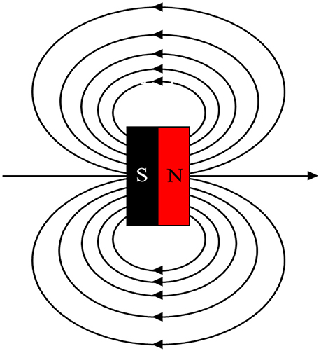
Figure 1. Field lines of diametrically magnetized cylinder, shown with open horizontal field lines.
Low-frequency oscillating magnetic fields have limited transmission range, however. The proposed solution is to use a second technology for long range networking. LoRa is a wireless radio modulation format for networking IoT systems which operates in the license-free range of the spectrum, at 868 MHz (European specification) or 915 MHz (North American specification). It is appealing for aboveground IoT purposes due to its low power consumption, low cost, potential for high interoperability between connected devices, and relatively long range (up to 1–10 miles). A Dragino LoRa module can easily add LoRa capability to an Arduino Uno or Arduino Mega microcontroller.
This study applies a novel combination of these two communication regimes (LoRa megahertz radio, and low-frequency magnetic signaling) for the development of an inexpensive, low-power IoT system, which is able to pass information from subterranean sensors to an aboveground IoT network. These sensors are designed for the purpose of leak detection in a municipal water system. One strategy for leak detection is to use flow meters to monitor for flow rate or volume changes (Zhang, 1996). In this scheme, a rapid change in flow rate at a pipe inlet or outlet may indicate that a leak has developed. Similarly, a leak can also be indicated if the difference between an upstream and a downstream flow measurement exceeds a predefined tolerance (Zhang, 1996). Another leak detection strategy is to use moisture sensors to monitor the moisture content of soil around buried pipes (Christodoulou et al., 2010). A localized area of high moisture may indicate a pipe leak in that location. In this paper, two sensors are developed which take advantage of these leak detection techniques: a self-powered flow meter with magnetic signaling, and a battery powered moisture sensor with magnetic signaling.
Section Electromagnetic Theory presents the electromagnetic theory which motivates the sensor design. Section Equipment lists the specifications of the test equipment used. Section Signaling With Oscillating Magnetic Fields describes three initial tests undertaken to evaluate the capabilities of low frequency magnetic signaling for subterranean IoT applications. Section Development of Communication System describes the components and functionality of the two leak detection sensors developed in this paper. Section Tests of Magnetic Telemetry IoT System presents the results of three tests of the leak detection system. Finally, Section Conclusions and Discussions discusses limitations of the current system, and possible improvements for future development.
Electromagnetic Theory
A spherical coordinates model for the fields generated by moving magnetic dipoles appears in Wangsness (1986). The dipole moment is along the z axis, is the direction of the radial distance, and is the direction of the polar angle:
where is the angular wavenumber m0 is the dipole moment, r is the distance from the source, θ is the polar angle from zenith, c is the speed of light, and ϵ0 is the vacuum permittivity constant: farad per meter. Permittivity is a measure of the ability of a material to resist the formation of an electric field within it. Generally, the near field is within one wavelength of a source, and the far field begins when r > 2λ. A transition zone exists for λ < r < 2λ. In the near field, terms with (kr)−3 dominate the magnetic field , and:
The near field amplitude quickly drops due to the (kr)3 term in the denominator. Thus, in the near-field, the strength of the magnetic field falls-off approximately according to the inverse of the distance cubed. For a 10 Hz source, the wavelength can be determined: . Since this study involves low-frequency oscillations less than 10 Hz, this signaling operates in the extreme near field.
The near-field magnetic field also induces propagation of a far-field electromagnetic signal with oscillations of energy between magnetic and electric fields. Propagating electric fields can travel long distances, but interact with most solids and liquids, including dielectrics and conductors. These interactions cause the movement of charged particles and dissipation of energy. Energy loss from propagating electromagnetic signals prevents the transmission of most electromagnetic waves through earth and water. This is the reason that low-power megahertz-frequency radio systems such as LoRa, are not, by themselves, suitable for subterranean communication.
Magnetic fields, however, do not interact significantly with most non-magnetic solids and liquids. This makes it possible for the near-field magnetic fields to propagate unimpeded through earth and water, making near-field magnetic signaling well-suited for short-range subterranean telemetry. This leads to the overall equipment design: the use of near-field magnetic signaling for short-range communication from subterranean sensors to surface receivers, and long-range LoRa wireless for aboveground data transmission.
Equipment
Preliminary testing and concept evaluation were conducted using a 3-axis Hall magnetometer (Honeywell HMR2300), with a digital resolution of 67 micro-gauss (Honeywell, 2006). A Hall magnetometer utilizes the Hall effect to perform magnetic field sensing. The Hall effect forms a voltage difference across an electrical conductor, perpendicular to the flow of a current, in the presence of an applied magnetic field perpendicular to both the conductor and the current flow. Measuring the voltage difference determines the strength of a magnetic field. The main drawbacks of the HMR2300 magnetometer are that its large size (~10.6 cm long) and the required external 120 V power supply make it unsuited for use in compact, inexpensive, low-power IoT systems.
Subsequent field tests switch to a more compact and substantially lower cost magnetoresistive 3-axis magnetometer (Honeywell HMC5883L). Magnetoresistance is the property wherein a material changes its directional electrical resistance based on the application of an external magnetic field. Magnetoresistive sensors are small and operate with low power consumption. The HMC5883L has a minimum digital resolution of 730 micro-gauss (Honeywell, 2010), the spatial resolution of 1.7 centimeters square, and can be controlled and powered by an Arduino microcontroller. Figure 2 shows an Arduino Mega with an HMC5883L magnetometer and a LoRa transmitter.
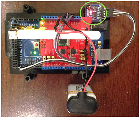
Figure 2. Arduino Mega with HMC5883L magnetometer (circled in green) and LoRa transmitter.
Except where noted, all tests in the study use cylindrical neodymium magnets with diametrical poling, a diameter of 6.35 mm, and a length of 25.4 mm. Residual magnetic flux density is ~1.32 T, with a pull force of roughly 6.4 kg.
Signaling with Oscillating Magnetic Fields
Signal Range
Tests were performed to evaluate the ability of magnetic fields, produced by rotating a diametrically-poled permanent magnet, to transmit frequency information over distances for use in a subterranean signaling system. The test setup is shown in Figure 3. The cylindrical magnet was rotated at ~2.3 Hz by a servo motor. The magnetic field was measured with an HMR2300 magnetometer placed radially from the rotating magnet at a distance of 7.62 m. Figure 4A shows a raw periodogram spectral estimate with a small, but distinct, frequency feature at 2 Hz. Figure 4B shows a smoother and lower variance spectrum produced by Welch averaging of the same signal with segments of 512 data points, which enhances the 2 Hz signal feature relative to the noise.
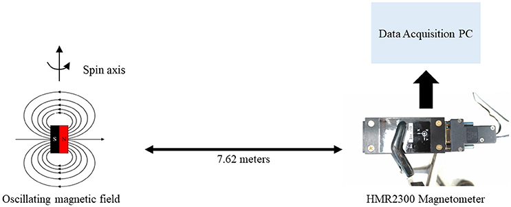
Figure 3. Diagram of signal range test.
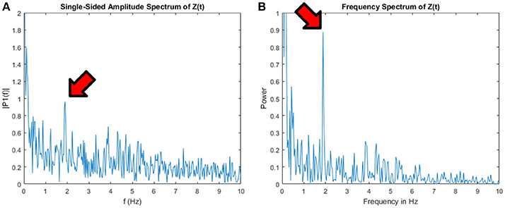
Figure 4. (A) Frequency feature detected at 2 Hz, at indoor range of 7.62 m. (B) The same spectrum smoothed using MATLAB pwelch function, yielding an enhanced feature.
Propagation Through Media
Experiments were also conducted to measure the extent to which distance and obstructing materials attenuate a rotating magnetic field. A servo motor was configured to spin a diametrically-poled neodymium magnet at ~2 Hz to create an oscillating field. The servo motor, power supply, and magnet were sealed in a 0.18-m2 waterproof housing that was weighted with rocks and gravel, as shown in Figure 5A. Figure 5B shows the waterproof housing containing the rotating magnet placed in a plastic storage bin. The HMR2300 measured the magnetic field strength at various distances horizontally from the rotating magnet. The magnetometer was oriented so that the front of the magnetometer (the X-axis sensor) was pointing toward the spinning magnet. Different test conditions were performed with the plastic storage bin empty (except for the sealed housing), filled respectively with 0.3 m of water, or with 0.3 m of soil, or empty but with an additional thin steel pipe surrounding the waterproof housing. An additional test was performed without the plastic bin or the waterproof housing, with the servo motor and magnet instead sealed inside an aluminum case.
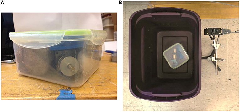
Figure 5. (A) servo motor with diametric magnet and power supply in waterproof housing, and (B) waterproof housing in plastic storage bin and HMR2300 magnetometer on stand.
Each test run records the signal strength vs. time for each axis at a rate of 20 samples per second. A Fourier Transform converts time-domain magnetic field information to the frequency domain and allows for determination of the frequency of the spinning magnet. The amplitude of the primary Fourier frequency feature determines the strength of the signal. Figure 6 shows a combination of the strength of the X, Y, Z frequency features, for the different media types, plotted on a log-log scale. It indicates that the magnetic signal propagates almost equally well through all tested obstructing media. The combined strength of the three (X, Y, Z) primary frequency features remained at least 10x above the noise floor in all test variations. Figure 7 shows that in open-air tests, the recorded signal strength attenuation agrees well with the theoretical near-field signal strength drop-off, and that these signals are detectable with a Hall effect magnetometer. Experimental results deviate from the theoretical calculation most noticeably at the closest range increment, where the magnetometer detects a smaller signal than what is predicted by the relationship. It is possible this may be due to an oversaturation of the sensitivity of the magnetometer at close range.
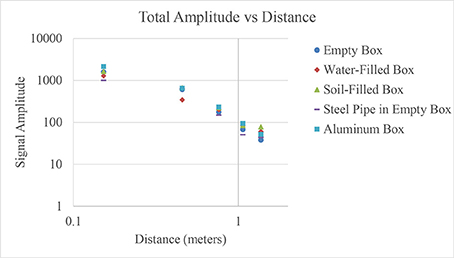
Figure 6. Combined (X, Y, Z) strength of primary frequency feature vs. distance, with rotating magnet source at ~2 Hz. Plotted on log-log scale with trendline.
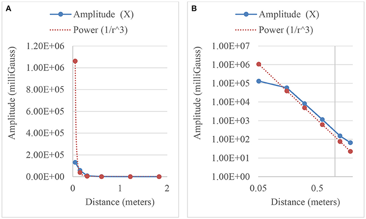
Figure 7. Comparison of experimentally observed (X-axis) and theoretical near-field values in air using HMR2300 magnetometer. (A) Shows results using base-10, while (B) uses a log-log scale.
Field Test of Range at Drain Pipe
A test was conducted to evaluate the ability of an oscillating magnetic signal to transmit out of a buried corrugated plastic stormwater sewer pipe. The HMR2300 magnetometer was placed ~2.3 m away from the rotating magnet source (straight-line distance). A soil/rock/gravel layer above the pipe was ~1.2 m thick. Figure 8 shows the frequency spectra in X, Y, Z directions after data were collected for 38.2 s. Figure 8D shows the axis directions of the HMR2300 magnetometer, as viewed from above. The X and Z sensors easily detected the 2.3 Hz signal.
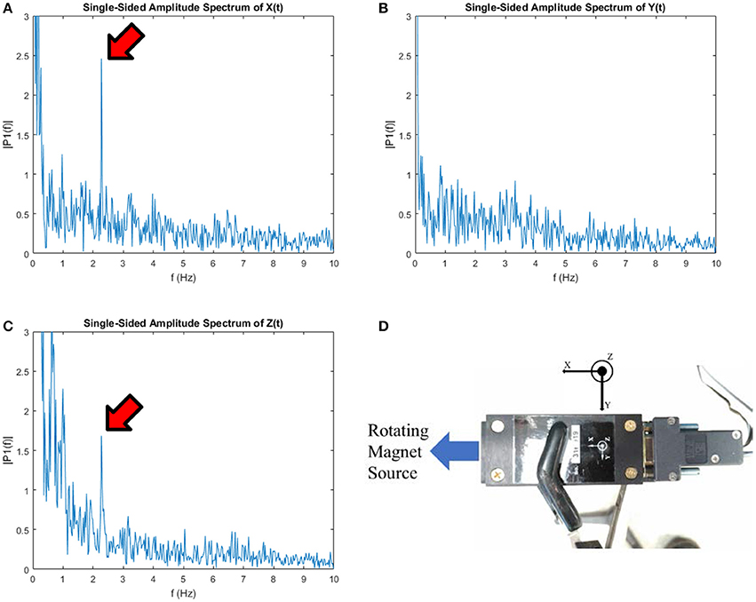
Figure 8. (A) X, (B) Y, and (C) Z frequency spectra after 38.2 s data acquisition. (D) Shows the orientation of magnetometer axes, as viewed from above.
Development of Communication System
Magnetic telemetry wasintegrated into a two-stage networked sensor communication system. In the first stage, magnetic signaling transmits information from a subterranean sensor to a surface mounted receiver. This receiver samples the signal using an attached magnetometer. A LoRa radio transmits information to a LoRa receiver, which uploads data to a server or data-acquisition computer.
Figure 9 shows a model of a rotating magnet flow meter: (a) is a 3D solid CAD assembly of the two-piece modular propeller, (b) is the nose cone part which holds a diametrically magnetized cylinder, and (c) is the propeller without the noise cone part. 3D-printing with polylactic acid (PLA) plastic is used to produce the part. When assembled, the nose cone is fixed to the propeller body. The propeller assembly rides on two low-resistance ceramic ball bearings, which are press-fitted into the 3D-printed propeller part. The two ball bearings ride on a non-metallic fiberglass bolt—with head underneath the nose cone, and threads extending out the back of the propeller. A fiberglass nut secures the bearings and keeps the propeller from sliding on the bolt. The protruding, threaded end of the bolt can be threaded into a mount for flow-meter installation. As the propeller rotates with the flow of the water, so does the diametric magnet, which creates an oscillating magnetic field. Faster-flowing water causes the field to oscillate faster, and measurements of the oscillating field provide wireless monitoring of the flow rate. The flow meter itself requires no wires, no power supply, and no physical connection to the LoRa network, unlike conventional flow meters currently available. The device does not require a data logging pick-up to be installed on the outside of the pipe, opening the possibility for it to be lowered into any section of existing subterranean pipe without excavation.
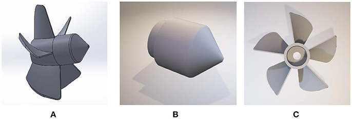
Figure 9. (A–C) Three views of rotating magnet flow meter SolidWorks Model.
Figure 10 shows a battery-operated moisture sensor that uses a low-power electric motor to rotate a diametrically magnetized neodymium magnet according to the amount of moisture detected. The rotating magnet produces an oscillating magnetic field, allowing information to be transmitted to an aboveground IoT-networked receiver, without the need for connecting wires, and with the potential to use less power than a radio-frequency transmitter. An Arduino Uno connects to a moisture sensor through a signal amplifier. As moisture content increases, the Arduino spins the motor faster. A lower power-consumption variation was also designed in which the Arduino Uno was replaced with a simple mechanical relay, to provide threshold-based moisture sensing.
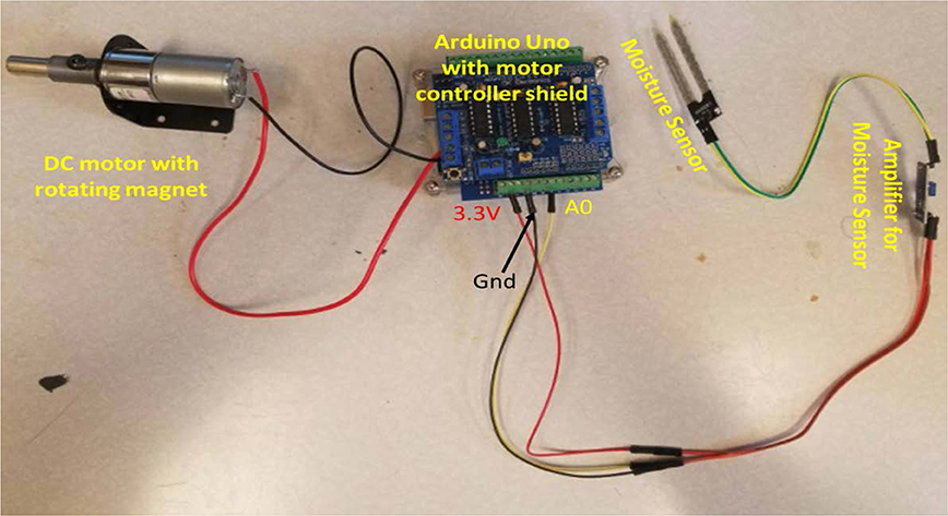
Figure 10. Rotating magnet moisture sensor design.
Figure 11 shows the complete IoT magnetic telemetry process. An oscillating magnetic field is produced by a rotating magnet. The primary sensing unit is an Arduino Mega powered by a 9-V battery. Connected to this are an HMC5883L 3-axis magnetometer and a Dragino LoRa Long Range Transceiver Shield. The device runs on custom Arduino code. It is configured to take 20 magnetic field strength samples per second using the magnetometer, resulting in 256 samples for each of the X, Y, and Z axes. The Arduino Mega then performs a 256-bin Fast Fourier Transform (FFT) on each axis dataset to calculate the frequency spectra. Next, the primary frequency feature for each axis is determined. The frequencies of these three features are then encrypted using the 128-bit AES AESLib.h encryption library. The three encrypted frequency values are transmitted via LoRa. The LoRa receiver consists of an Arduino Uno with a Dragino LoRa Long Range Transceiver Shield. Custom Arduino code receives and decrypts the LoRa transmission using a pre-shared key. Data are uploaded via USB serial port to a data-acquisition computer.
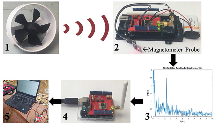
Figure 11. Complete IoT magnetic telemetry process.
Tests of Magnetic Telemetry IOT System
Magnetic Telemetry Moisture Sensor
A system test of the rotating magnet moisture sensor was performed to verify proper LoRa integration, as well as to determine the feasibility of using a rotating magnet to transmit information through a 0.14-m-thick rebar-reinforced concrete slab. Test details are shown in Figure 12. The relay-based moisture sensor is placed into damp soil, and a rotating magnet source is buried under a concrete slab. The Arduino Mega magnetometer-receiver/LoRa-transmitter unit was placed on the surface of the concrete, and the Arduino Uno LoRa receiver was connected to a data-acquisition computer. Results are shown in Figure 13. An oscillation frequency of 1.6 Hz was detected, indicating that the moisture content threshold of the soil was reached.
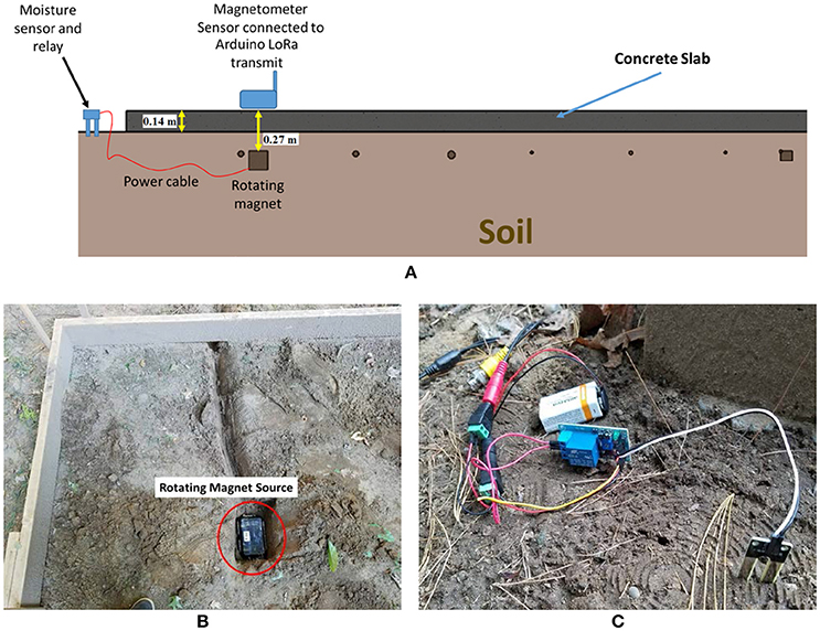
Figure 12. (A) Schematic of moisture sensor test setup, (B) rotating magnet source before being buried, and before concrete slab is poured, (C) moisture sensor with low-power relay design.
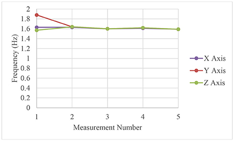
Figure 13. Recorded frequency of moisture sensor transmission through concrete slab.
Calibration of Magnetic Telemetry Flow Meter
A rotating magnet flow meter with magnetometer/LoRa transceiver system were tested in a hydraulic laboratory flume. Figure 14A shows the Arduino Uno LoRa receiver connected to a data acquisition computer. The flume is visible in the background with a submerged 0.1016-m inner-diameter PVC pipe, which contains the rotating magnet flow meter. Figure 14B shows water flowing through the submerged flow-meter pipe. The Arduino Mega with a magnetometer and the LoRa transmitter is enclosed in a weatherproof box visible on top of an aluminum shelf. During the test, the magnetometer successfully detected the oscillating magnetic field, and the frequency information was transmitted wirelessly to the Arduino Uno LoRa receiver.
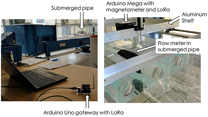
Figure 14. (Left) LoRa Arduino receiver connected to data-acquisition PC, and (Right) rotating magnet flow meter submerged in flume.
In this test, the flow meter was equipped with a larger magnet (9.525 mm diameter, up from 6.25 mm). A dam with a circular, 75 mm diameter inner drain was installed in the flume. A rectangular thin-plate weir was installed ~1 m downstream of the circular drain dam, as shown in Figure 15. The weir allows for calculation of water flow by measuring the depth of the water flowing over the weir. By making the reasonable assumption that the volume of water between the circular drain dam and the weir is roughly constant, calculating water flow over the weir gives a good measure of water flow through the dam, and therefore, through the rotating magnet flow meter. The height of the water flowing over the weir is converted to flow using the Kindsvater and Carter (Water Measurement Manual, 2001) weir equation:
where CKC, aKC, kb are coefficient values, g is acceleration due to gravity, h is the height of the water above the weir plate, P is the height of the weir plate, and b is the width of the weir opening. CKC, aKC, and kb are determined by the relationship b/B, where B is the width of the flume (1 m). Additionally, a Venturi flow meter was used to measure the flow rate of water entering the flume, upstream of the circular drain dam. It gives flow in units of inches of H2O which is subsequently converted to flow rate. The magnetic flow meter was calibrated at three flow rates for which the flume motor was set to 15, 23, and 30 Hz, respectively. Results are given in Figure 16. Inspection of Figure 16B shows that the magnetic flow meter (blue) tracks very well with the calculated flow rates obtained by using the weir method (green). This indicates that as flow increases, the frequency of the magnetic flow meter increases appropriately, such that flow rate can be readily calculated. It was noted during the testing that at the two higher flow rates (23 and 30 Hz), the upstream portion of the flume filled faster than the water could drain through the flow meter. This is evidenced by the Venturi flow meter measurement, which measured water volume entering the flume. It is the red line in Figure 16B. As the flume pump motor speed increased, the flow into the flume increased faster than the flow leaving the flume. Thus, the red Venturi meter line has a steeper slope than the other two measurements. Figure 17 shows extrapolated linear trendlines comparing actual flow rate (as determined by the previous weir calculation), with rotating magnetic flow meter rotation frequency. These trendlines provide frequency-flow conversion for the rotating magnet flow meter.
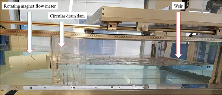
Figure 15. Flow calibration test setup for rotating magnet flow meter.
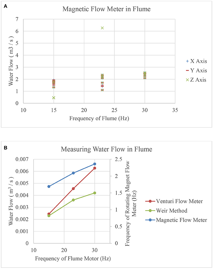
Figure 16. (A) Recorded X, Y, Z axis frequencies of rotating magnet flow meter during flume testing, using IoT system. (B) Median frequency at each flow rate, along with flow measurements using Venturi flow meter and weir method.
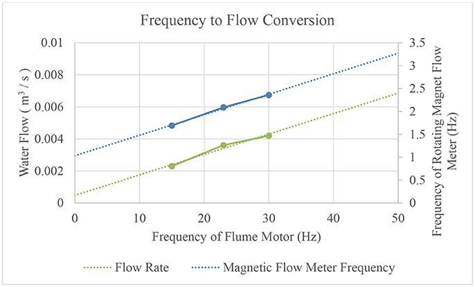
Figure 17. Frequency to flow conversion for rotating magnet flow meter.
Magnetic Telemetry Flow Meter Test in Buried Pipe
A PVC pipe was buried on a sandy hillside, as shown in Figures 18A–D. The pipe was 3.7 m long with an inner diameter of 0.1016 m. It was buried 0.3–0.46 m below the ground surface. A rotating magnet flow meter (with the standard 6.35 mm diameter magnet) was installed approximately halfway through the length. The system was fed by a rain barrel filled by a garden hose, illustrated in Figure 18A. Figure 18D shows two drains on the system—one has a 3.81 cm diameter, and a second smaller drain has a 1.905 cm diameter. This secondary drain splits off from the main pipe approximately one foot below the flow meter. Opening and closing this drain can be used to emulate a pipe leak downstream of the flow sensor (Hunaidi et al., 2000). The goal is to detect a flow difference caused by opening the secondary drain valve, i.e., detecting a leak. The ratio of the size of the drain area of the primary drain plus the “leak” drain, compared to the area of the primary drain alone, is:
This indicates that in the test, opening the “leak” drain should increase water flow by a factor of 1.25.
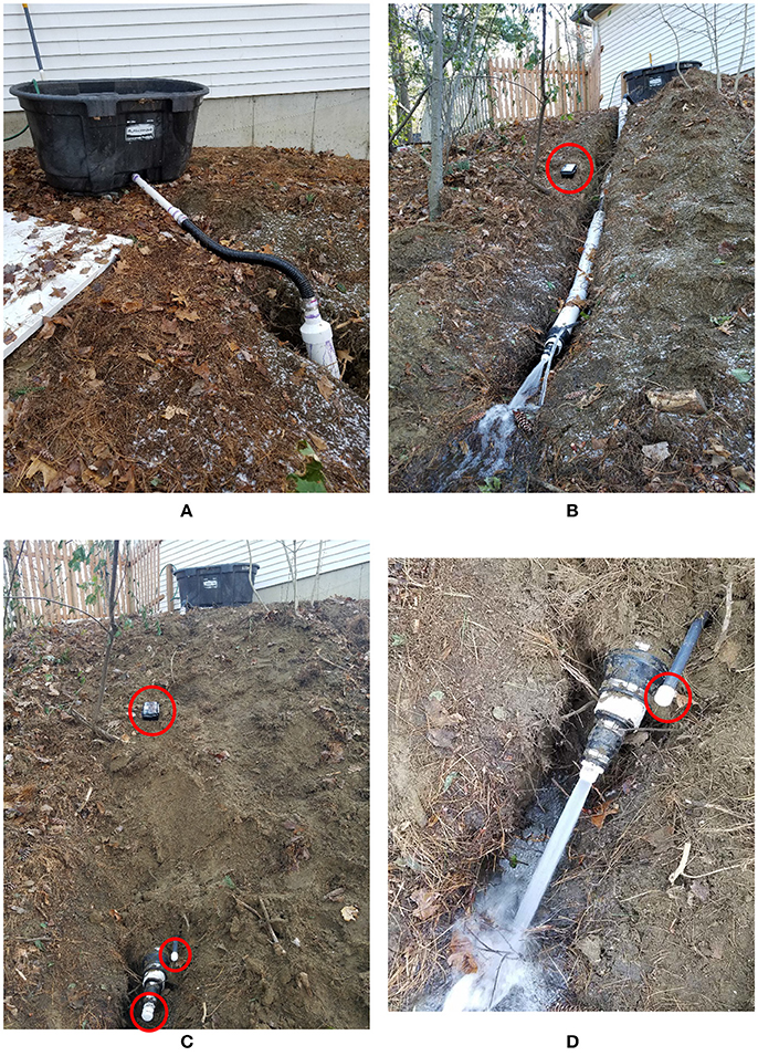
Figure 18. (A) Rain barrel water source for buried pipe containing rotating magnet flow meter. (B) Pipe containing rotating magnet flow meter before burial. Arduino Mega unit with magnetometer and LoRa transmitter is indicated. (C) Pipe after burial. The Arduino Mega unit and the pipe's two drain outlets are circled in red. (D) Water drains through the larger of the two drain outlets. The smaller drain outlet is circled in red.
Data were acquired by placing the Arduino magnetometer unit on the ground surface near to the location of the flow meter. After the pipe was buried, data were gathered: with only the primary drain open, the LoRa magnetic transceiver system detected a median flow rate of 6.29 Hz. When the “leak” drain is opened, frequency increased to a median value of 7.85 Hz. This represents a flow increase of 125%, the expected increase given the size of the pipes. While this is a simplification of the fluid dynamics processes, it does demonstrate proper functioning of the rotating magnet flow meter, as well as the LoRa wireless integration. The sensor system was able to detect changes in water flow associated with leak development.
Conclusions and Discussions
In this study, a series of experiments are performed to assess the viability of magnetic telemetry for subsurface infrastructure monitoring. Magnetic signals propagate well through air and a variety of urban-relevant media. Tests in a buried drain demonstrate these signal transmission capabilities in a real-world environment. A novel two-step transmission system is developed, in which a magnetic flow meter uses oscillating magnetic fields to transmit flow information to a custom-built low-cost, low-power, magnetometer-equipped LoRa IoT device. This two-step process is also used to gather and interpret data from a rotating magnet moisture sensor. These two magnetic signaling sensors are evaluated in a variety of test environments, including a concrete slab testbed, a flume, and a buried PVC pipe. The results provide evidence for the potential effectiveness of this type of sensor for low cost IoT-capable flow monitoring, for applications such as leak detection.
While the completed magnetic sensing and LoRa system shows good system performance, it may be desirable to increase the transmission range of the magnetic sensor. The diametrically-poled neodymium magnet used in the majority of tests has a magnetic material volume of ~3.212 cm3. Increasing from a 0.635 cm to a 1.27 cm diameter magnetic cylinder would result in a 4-fold increase in magnetic material and magnetic field strength. Because of the experimentally-verified inverse-cube signal deterioration experienced in near-field magnetic sensing, this corresponds to a range increase by a factor of 41/3 = 1.59. An increase in material volume at this scale is relatively easy to achieve with the current design; however, significantly larger magnet volumes may be prohibitive due to the size restraints associated with fitting in small pipes, as well as the energy requirements to move a larger mass. A very large pipe with strong water flow may accommodate a larger device: for example, a 10.16 cm diameter neodymium cylinder 15.24 cm long would provide an 11.6-fold range increase compared to the magnet used in the current design.
Another way to improve magnetic sensing range is to use a more sensitive magnetometer. While the HMC5883L is appealing for IoT applications due to its extremely low cost, it may be advantageous to have certain IoT units equipped with more sensitive magnetometers.
IoT-enabled flow sensors with magnetic telemetry have the potential to integrate with and supplement other IoT and infrastructure monitoring systems. Further refinement of the technology will continue to bring these devices closer to marketability. A logical next step in system design is the integration of many IoT flow sensors into two-way communication networks, leveraging the penetrating capabilities of magnetic signaling to remotely control subsurface sensors.
Author Contributions
DO and DB designed and built the devices and performed the experiments with contributions from RF. MQ, HM, and CO assisted with LoRa networking. DO wrote the manuscript with support from DH and TX. DO and DB prepared the figures. DH, TX, and DB conceived the original idea. DH and TX supervised the project.
Funding
This work has been supported by US National Science Foundation grants 1647095 and 1640687, the University of Vermont SPARK Fund, and VT EPSCoR.
Conflict of Interest Statement
The authors declare that the research was conducted in the absence of any commercial or financial relationships that could be construed as a potential conflict of interest.
Acknowledgments
The authors would like to thank Jon Miller and White River Technologies for technical advice and use of the HMR2300 magnetometer.
References
ASCE (2017). Infrastructure Report Card. Available online at: https://www.infrastructurereportcard.org/americas-grades/
Adedeji, B. K., Hamam, Y., and Abe, B. T. M. (2017). Leakage detection and estimation algorithm for loss reduction in water piping networks. Water 9:773. doi: 10.3390/w9100773
Christodoulou, S., Agathokleous, A., Kounoudes, A., and Milis, M. (2010). Wireless sensor networks for water loss detection. Eur. Water. 30, 41–48.
Gerginov, V. (2017). Prospects for magnetic field communications and location using quantum sensors. Rev. Sci. Inst. 88:125005. doi: 10.1063/1.5003821
Goulet, J. A. Coutu, S., and Smith, I. F.C. (2013). Model falsification diagnosis and sensor placement for leak detection in pressurized pipe networks. Adv. Eng. Inform. 27, 261–269. doi: 10.1016/j.aei.2013.01.001
Hunaidi, O., Chu, W. T., and Wang, A. (2000). Detecting leaks in plastic pipes. Am. Water Works Assoc. 92, 82–94. doi: 10.1002/j.1551-8833.2000.tb08819.x
Huston, D., and Xia, T. (2017). “EAGER: Underground Infrastructure Sensing, Mapping and Modeling for Smart Maintenance, Sustainability and Usage,” Poster Session Presented at: Eighth Annual Cyber-Physical Systems Principal Investigators' Meeting (Alexandria, VA).
Huston, D., Xia, T., Burns, D., Orfeo, D., Zhang, Y., and Ou, C. (2017). “Mapping, assessing and monitoring urban underground infrastructure,” in 11th International Workshop on Structural Health Monitoring 2017 (Stanford, CA: DEStech Publications, Inc).
Khulief, Y. A., Khalifa, A. E., Ben-Mansour, R., and Habib, M. A. (2012). Acoustic detection of leaks in water pipelines using measurements inside pipe. J. Pipeline Syst. Eng. Pract. 3, 47–54. doi: 10.1061/(ASCE)PS.1949-1204.0000089
Lambert, A. O. (2002). International report: water losses management and techniques. Water Sci. Technol. 2, 1–20.
Liu, Z., and Kleiner, Y. (2013). State of the art review of inspection technologies for condition assessment of water pipes. Measurement 46, 1–15. doi: 10.1016/j.measurement.2012.05.032
Montestruque, L., and Lemmon, M. (2008). “CSOnet: A metropolitan scale wireless sensoractuator network”, in MODUS '08: International Workshop on Mobile Device and Urban Sensing.
Montestruque, L. A., and Ruggaber, T. P. (2007). “The Use of a Decentralized Wireless Sensor Network for CSO Abatement and Control,” in World Environmental and Water Resources Congress 2007 (Tampa, FL).
Picos, R., Lopez-Grifol, A., Martinez-Villagrassa, D., Simo, G., Wenger, B., and Dunnermann, J. (2016). “Development of a low-cost tethered balloon sensing system for monitoring the lower atmosphere,” in EGU General Assembly Conference Abstracts (Vienna).
Puust, R., Kapelan, Z., Savic, D., and Koppel, T. (2010). A review of methods for leakage management in pipe networks. Urban Water J. 7, 25–45. doi: 10.1080/15730621003610878
Rajani, B., and Kleiner, Y. (2004). “Non-destructive inspection techniques to determine structural distress indicators in water mains,” in Evaluation and Control of Water Loss in Urban Water Networks (Valencia), 1–20.
Water Measurement Manual (2001). Water Resources Technical Publication 2001; Revised Reprint 2001:[US Department of the Interior: Bureau of Reclamation]. Available online at: https://www.usbr.gov/tsc/techreferences/mands/wmm/chap07_06.html
Keywords: magnet, telemetry, IoT, leak detection, flow meter, moisture sensor, Arduino, underground
Citation: Orfeo D, Burns D, Farrell R, Qin M, Mitchell H, Ou C, Xia T and Huston DR (2018) Mechano-Magnetic Telemetry for Underground Water Infrastructure Monitoring. Front. Built Environ. 4:29. doi: 10.3389/fbuil.2018.00029
Received: 16 February 2018; Accepted: 24 May 2018;
Published: 19 June 2018.
Edited by:
Branko Glisic, Princeton University, United StatesReviewed by:
David Lattanzi, George Mason University, United StatesJónatas Miguel De Almeida Valença, Universidade de Lisboa, Portugal
Copyright © 2018 Orfeo, Burns, Farrell, Qin, Mitchell, Ou, Xia and Huston. This is an open-access article distributed under the terms of the Creative Commons Attribution License (CC BY). The use, distribution or reproduction in other forums is permitted, provided the original author(s) and the copyright owner are credited and that the original publication in this journal is cited, in accordance with accepted academic practice. No use, distribution or reproduction is permitted which does not comply with these terms.
*Correspondence: Dryver R. Huston, ZHJ5dmVyLmh1c3RvbkB1dm0uZWR1