 Hiroki Akehashi
 Kotaro Kojima
 Kohei Fujita
 Izuru Takewaki
- 1Department of Architecture and Architectural Engineering, Graduate School of Engineering, Kyoto University, Kyotodaigaku-Katsura, Kyoto, Japan
- 2Faculty of Design and Architecture, Kyoto Institute of Technology, Kyoto, Japan
The critical nonlinear response considering soil-structure interaction is investigated for a base-isolated building under a double impulse as a substitute for near-fault earthquake ground motions. The complicated model of the nonlinear base-isolated building considering soil-structure interaction is first modeled as a two-degree-of-freedom (2DOF) system (SDOF superstructure and base-isolation story) on a swaying-rocking spring-dashpot system. Then the 2DOF system on a swaying-rocking spring-dashpot system is transformed into an SDOF system on a swaying-rocking spring-dashpot system by neglecting the mass on the base-isolation story. Finally the SDOF system on a swaying-rocking spring-dashpot system is further transformed into an SDOF system by neglecting the mass and moment of inertia of the base mat. Since an explicit expression had been derived in the previous paper on the maximum elastic-plastic response of an SDOF damped bilinear hysteretic structure subjected to the “critical double impulse input” causing the maximum response for variable interval of impulses with the input level kept constant, this expression is applied to the finally transformed SDOF system. The transformation of structural viscous damping in different elements is another new aspect in this paper. The reliability and accuracy of the proposed simplification methodology are investigated by comparing with the results by the time-history response analysis under the critical double impulse and the one-cycle sine wave as a representative of the main part of the near-fault earthquake ground motion.
Introduction
A great deal of useful records from recent earthquakes enabled a clear classification of earthquake ground motions in view of their characteristics (Abrahamson et al., 1998). Especially this observation is being accelerated due to dense arrangement of high-performance measurement systems. One is a short-duration intensive ground motion characterized by a near-fault ground motion and another one is a long-period and long-duration ground motion mostly with a far fault (see Takewaki et al., 2011). It is widely understood in the field of earthquake resistant design of structures that surface-soil properties influence greatly earthquake ground motions at ground surface. For this reason, the surface soil types (soil, rock) are important factors for such classification as well as fault mechanisms. On the effects of near-fault ground motions on structural inelastic responses, various viewpoints have been provided (for example Bertero et al., 1978; Hall et al., 1995; Sasani and Bertero, 2000; Mavroeidis and Papageorgiou, 2003; Alavi and Krawinkler, 2004; Makris and Black, 2004; Mavroeidis et al., 2004; Kalkan and Kunnath, 2006; Khaloo et al., 2015). Fling-step (parallel to the fault plane) and forward-directivity (normal to the fault plane) are often discussed and used recently for designating such near-fault ground motions. Representatives of recent related earthquake ground motions are Northridge earthquake in 1994, Hyogoken-Nanbu (Kobe) earthquake in 1995, Chi-Chi (Taiwan) earthquake in 1999 and Kumamoto earthquake in 2016. Recently strong earthquakes occurred in Italy, e.g., the 2009 L'aquila (Di Sarno et al., 2011) and 2016–2017 Central Italy earthquakes. Such seismic events had significant near field effects.
For simple but essential discussion, two or three half-cycle sine waves have been extracted from fling-step and forward-directivity motions (see Figure 1). As the first step, many engineers discussed mainly the elastic response under the near-fault ground motions. Since there are many parameters (e.g., duration and amplitude of pulse, predominant period, ratio of pulse frequency to structure natural frequency) and the corresponding numerical parametric analysis is extremely complicated for elastic-plastic response, the treatment of only elastic response was reasonable. However, the investigation on elastic-plastic response is inevitable from the reliable damage assessment and enhancement of true safety of structures.
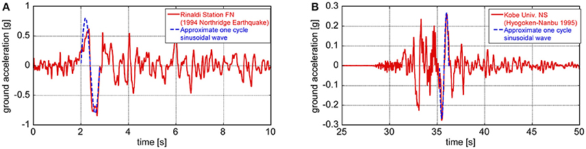
Figure 1. Transformation of main part of recorded pulse-type ground motion into one-cycle sine wave: (A) Fault-normal component at Rinaldi station (Northridge earthquake in 1994), (B) NS component (nearly fault-normal) at Kobe University (Hyogoken-Nanbu earthquake in 1995) (Kojima and Takewaki, 2016).
Kojima and Takewaki (2015a) introduced an innovative approach using the double impulse as expressed in Figure 2A to overcome such complex difficulty. The double impulse substitutes for the main effect of the fling-step near-fault ground motion and the explicit maximum elastic-plastic response was obtained in a structure under the “critical double impulse” using the smart energy balance law. The “critical input” is closely related to the critical excitation method (see Drenick, 1970; Takewaki, 2007). Since only the free vibration appears under such double impulse, their approach enabled the simple expression of complex elastic-plastic response. The introduction of the triple impulse enabled the successful application of the methodology for the fling-step motion to a more realistic forward-directivity motion by Kojima and Takewaki (2015b) (see Figure 2B). This approach using impulses was further extended to long-period, long-duration ground motions in terms of multi impulses (Kojima and Takewaki, 2015c).
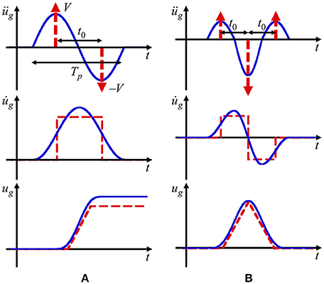
Figure 2. Modeling of main part of near-fault ground motion, (A) Fling-step and double impulse, (B) Forward-directivity and triple impulse, Kojima and Takewaki (2015a).
In the last century, the field of earthquake-resistant design was developed successfully and the resonance played a key role in the damage analysis of structures (e.g., Elnashai and Di Sarno, 2008). Once an input level is specified, the resonant equivalent frequency is required to be analyzed by changing the input frequency of a sine wave parametrically (Caughey, 1960a,b; Iwan, 1961, 1965a,b; Roberts and Spanos, 1990; Liu, 2000). Following this approach, Luco (2014) presented an interesting result on nonlinear steady-state response for a base-isolated building with nonlinear isolators on flexible ground. He employed the equivalent linearization technique to draw the resonance curve which requires the repetition in the determination of equivalent parameters and the sweeping of excitation frequency. On the other hand, such computation without repetition is realized by the double impulse. The double impulse enables the smart capture of the resonance through an energy balance law and the timing of the second impulse can be obtained as the time at which the zero restoring force is attained after the first impulse. The maximum elastic-plastic response after the first impulse can be obtained by transforming the initial kinetic energy given by the first impulse into the sum of elastic strain energy, hysteretic energy and the damping energy (Kojima et al., 2017).
In this paper, the critical nonlinear response is investigated for a base-isolated building on flexible ground under a double impulse as a good substitute for near-fault earthquake ground motions. The complex model of the nonlinear base-isolated building considering soil-structure interaction is first modeled using a two-degree-of-freedom (2DOF) system (SDOF superstructure and base-isolation story) on a swaying-rocking spring-dashpot system which represents the flexibility and damping of ground. Then the 2DOF system on a swaying-rocking spring-dashpot system is transformed into an SDOF system on a swaying-rocking spring-dashpot system by neglecting the mass on the base-isolation story. Finally the SDOF system on a swaying-rocking spring-dashpot system is further transformed into an SDOF system by neglecting the mass and moment of inertia of the base mat. Since an explicit expression had been derived in the previous work (Akehashi et al., 2018) on the maximum elastic-plastic response of an SDOF damped structure with bilinear hysteresis under the “critical double impulse input” which causes the maximum response for variable impulse interval with the input level kept constant, this expression is applied to the finally transformed SDOF system. The transformation of structural viscous damping in different elements is another new aspect in this paper. The reliability and accuracy of the proposed simle methodology are investigated by comparing with the results by the time-history response analysis to the critical double impulse and the one-cycle sine wave as a representative of the main part of the near-fault earthquake ground motion.
Base-Isolated Building Considering Soil-Structure Interaction and Its Modeling Into 2DOF Model on Swaying-Rocking Spring-Dashpot System
Consider a base-isolated building on ground as shown in Figure 3. The superstructure is modeled as an SDOF system and the stiffness and damping of the ground are represented by a swaying-rocking spring-dashpot system. The base-isolation story is assumed to consist of lead rubber bearings and is modeled by a shear spring with bilinear hysteresis. Then the total system is a 2DOF shear building model supported by the swaying-rocking spring-dashpot system. This total system is finally transformed into an SDOF system as shown in Figure 4. The masses of the superstructure, the base-isolation story and the base mat are denoted by mU, mI, m0 and the corresponding mass moments of inertia are denoted by IU, II, I0. Let dyI and αI denote the yield deformation and the post-yield stiffness ratio to the initial stiffness at the base-isolation story.
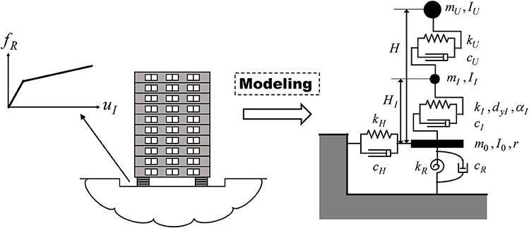
Figure 3. Base-isolated building considering soil-structure interaction and its modeling into 2DOF model on swaying-rocking spring-dashpot system.
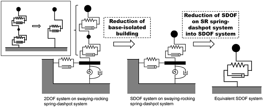
Figure 4. Transformation of total system into an SDOF system through two-stage procedure.
Let uU, uI, uH, θR denote the deformation of the superstructure, the deformation of the base-isolation story, the swaying displacement and the angle of rotation of the base mat. The stiffnesses and damping coefficients of the superstructure and the base-isolation story are denoted by kU, kI, cU, cI. The swaying-rocking stiffnesses and damping coefficients of the spring-dashpot system of the ground are denoted by kH, kR, cH, cR. H is the height of the equivalent mass from the base mat.
Transformation of 2DOF System on Swaying-Rocking Spring-Dashpot System into SDOF System on Swaying-Rocking Spring-Dashpot System
The 2DOF system consisting of an SDOF superstructure and a base-isolation story on rigid ground is transformed into an SDOF system as shown in Figure 5 by neglecting the degree of freedom just above the base-isolation story. Then the total system is the SDOF system on a swaying-rocking spring-dashpot system. In this section, the 2DOF system on rigid ground is transformed into an SDOF system. Let ue, ke, ce denote the displacement of the transformed SDOF mass (= superstructure mass), the stiffness and damping coefficient of the transformed SDOF model.
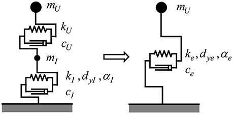
Figure 5. Transformation of 2DOF system consisting of an SDOF superstructure and a base-isolation story into an SDOF system.
The procedure of neglecting the mass just above the base-isolation story and neglecting the corresponding degree of freedom is explained.
The dynamic equilibrium at the degree of freedom just above the base-isolation story can be expressed by
The stiffness ke of the equivalent SDOF model can be derived based on the series spring model.
On the other hand, the damping coefficient ce of the equivalent SDOF model can be related to the respective damping coefficients cU, cI. The following equation can be obtained from the Fourier transform of Equation (1).
From Equation (3), ce can be obtained as follows.
where .
From the static equilibrium at the yielding point, the yield deformation is expressed by
From 1/(αeke) = 1/(αIkI)+1/kU, the second stiffness ratio of the equivalent SDOF model can be expressed by
Transformation of SDOF System on Swaying-Rocking Spring-Dashpot System into SDOF System
By neglecting the degrees of freedom at the base mat (the mass and moment of inertia of the base mat are neglected), the SDOF system on a swaying-rocking spring-dashpot system can be transformed into an equivalent SDOF system as shown in Figure 6.
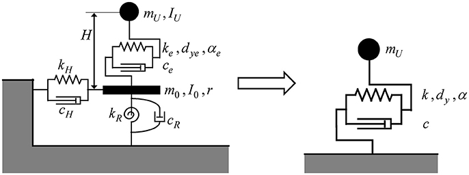
Figure 6. Transformation of SDOF system on a swaying-rocking spring-dashpot system into an SDOF system.
Let u and us denote the total displacement of the equivalent SDOF system and the deformation of the equivalent SDOF system (displacement without swaying-rocking component). k and c are the stiffness and damping coefficient of the equivalent SDOF system.
The equation of motion of the SDOF system on a swaying-rocking spring-dashpot system can be expressed by
The horizontal and rotational dynamic equilibriums at the base mat can be described by
where u is the following total displacement of the equivalent SDOF system.
The equation of motion of the equivalent SDOF system can be expressed by
Equations (8, 9) are rearranged into
The static series-spring assumption leads to
On the other hand, the dynamic series-spring assumption provides
The damping coefficient of the equivalent SDOF system can be derived as
where ,
From the static equilibrium at the yielding point, the yield deformation can be expressed by
From , the second stiffness ratio after yielding of the equivalent SDOF system can be expressed by
Explicit Expression on Critical Elastic-Plastic Response Under Double Impulse
In the previous work (Akehashi et al., 2018), an explicit expression on the peak deformation of a damped SDOF system of bilinear hysteresis under the critical double impulse has been derived. That expression is used in this paper for predicting the response of a base-isolated building on ground. In particular the maximum elastic-plastic deformation of the base-isolation story under the critical double impulse is obtained by relating that deformation with the total deformation of the equivalent SDOF model.
A damped SDOF system of bilinear hysteresis is considered which has the mass mU, initial stiffness k and damping coefficient c. This system is subjected to the double impulse üg(t) = Vδ(t)−Vδ(t−t0) of ground acceleration as shown in Figure 7. This SDOF system is the same as that in Figure 6. V is the given velocity value of the first and second impulses. In addition, t0 is the time interval between two impulses and this value is treated as a variable in the problem of finding the critical double impulse. The ratio of the post-yield stiffness to the initial one is designated by α (α>0). The yield deformation and force are expressed by dy and fy. The bilinear hysteretic restoring-force characteristic is described by f(u). Let , T1 = 2π/ω1, , denote the undamped natural circular frequency, the undamped natural period, the damped natural circular frequency and the damped natural period, respectively. Furthermore the damping ratio, the displacement of the mass relative to the ground (deformation of the system) and the restoring force in the model are denoted by h, u, and f, respectively. The time derivative is designated by an over-dot.
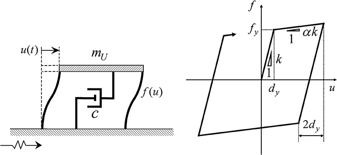
Figure 7. Damped SDOF model and its bilinear hysteretic restoring-force characteristic.
Extraction of Maximum Deformation of Base-Isolation Story from the Total Response
Once the maximum deformation of the equivalent SDOF model is obtained, the corresponding maximum deformation of the base-isolation story can be derived. This procedure is explained in this section.
The total displacement u consists of several components including the base mat displacement and rotation (see Figure 8).
Then the corresponding deformation of the base-isolation story can be expressed by
where fR denotes the common restoring force in the respective spring. When the maximum displacement umaxi and the maximum restoring force fRmaxi are substituted into u and fR in Equation (21), the maximum deformation of the base-isolation story can be obtained. Here the maximum displacement after the first impulse is denoted by umax1 and that after the second impulse by umax2. The maximum restoring force in the base-isolation story can be obtained as follows depending on the input level.
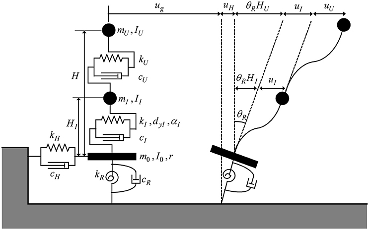
Figure 8. Relation of deformation components.
[Case 1:uImax1, uImax2, Case 2:uImax1]
[Case 2:uImax2, Case 3:uImax1]
[Case 3:uImax2]
Figure 9 shows the four cases depending on the input level. Case 3-1 is the case where the second impulse acts at the zero restoring force in the unloading process and Case 3-2 is the case where the second impulse acts at the zero restoring force in the reloading process.
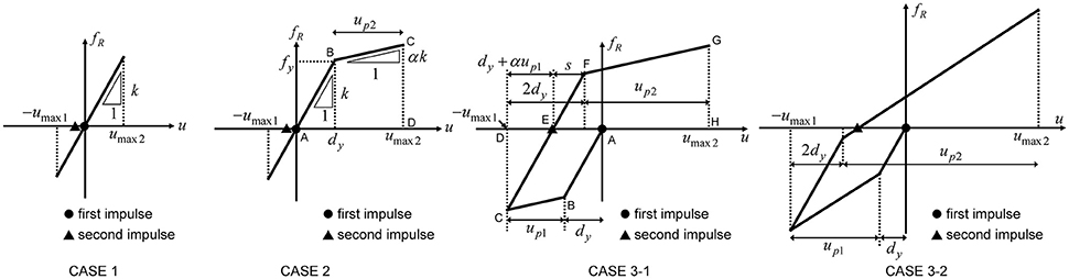
Figure 9. Four cases of response process depending on input level.
Accuracy Investigation of the Proposed Transformation into SDOF System Through the Comparison of the Closed-Form Expression with the Result by Time-History Response Analysis
In order to investigate the reliability and validity of the proposed expression under the double impulse with the velocity V, the time-history response analyses of the 2DOF system on the swaying-rocking spring-dashpot system under the double impulse and the one-cycle sine wave have been performed. The second impulse was input at the timing such that the maximum deformation at the base-isolation story after the second impulse attains the maximum.
In this investigation, the adjustment of the input levels between the double impulse and the one-cycle sinusoidal wave is important from the viewpoint of the equivalence of the maximum Fourier amplitude. The adjustment procedure is explained in the references (Kojima and Takewaki, 2016; Kojima et al., 2017). The one-cycle sine wave corresponding to the critical double impulse can be expressed as follows.
where Vp/V = 1.2222 (V: the velocity amplitude of the double impulse) (Kojima and Takewaki, 2016; Kojima et al., 2017). Vp denotes the maximum velocity of the sine wave. In addition, and ωp = 2π/Tp denote the period and the circular frequency, respectively, of the sine wave. The critical time interval obtained above is used for in Equation (25).
The swaying-rocking spring-dashpot parameters are evaluated by the formula due to Parmelee (1970) and are expressed by
where the Poisson's ratio ν = 0.35, the mass density ρ = 1.8[t/m3], the shear wave velocityVs = 200, 133, 100[m/s] for Soil type 1, 2, 3 (the shear modulus ). The radius of the disk equivalent to the superstructure floor and the foundation mat is given by (assuming 1.0 × 10³(kg/m2) for the superstructure floor mass and 2.0 × 10³(kg/m2) for the foundation mat). The mass moments of inertia are given by . Let Ts and TBI denote the fundamental natural period of the super structure with fixed base and the fundamental natural period of the rigid super structure on the base-isolation story.
The given parameters for the 10-story model are as follows:
mU = 800[t], mI = m0 = 160[t]
On the other hand, the given parameters for the 20-story model are as follows:
mU = 1600[t], mI = m0 = 160[t]
The left figure in Figure 10A presents the comparison of the maximum deformations (after the first impulse and after the second impulse) of the models reduced from a 10-story building on the rigid ground. The solid line indicates the values based on the explicit expression explained in section Explicit Expression on Critical Elastic-Plastic Response Under Double Impulse (Akehashi et al., 2018) and the broken line presents the maximum value (top displacement) by the time-history response analysis for the 2DOF system on the swaying-rocking spring-dashpot system under the critical double impulse. On the other hand, the dotted line illustrates the maximum value (top displacement) by the time-history response analysis for the 2DOF system on the swaying-rocking spring-dashpot system under the corresponding one-cycle sine wave. It can be observed that the closed-form expressions are accurate enough. Furthermore, the right figure in Figure 10A presents the comparison of the maximum deformations (after the first impulse and after the second impulse) in the base-isolation story of the model on the rigid ground. The solid line indicates the value extracted from the explicit expression (Akehashi et al., 2018) as explained in section Extraction of Maximum Deformation of Base-Isolation Story from the Total Response and the broken line presents the maximum value in the base-isolation story by the time-history response analysis for the 2DOF system on the swaying-rocking spring-dashpot system under the critical double impulse. On the other hand, the dotted line illustrates the maximum value in the base-isolation story by the time-history response analysis for the 2DOF system on the swaying-rocking spring-dashpot system under the corresponding one-cycle sine wave. It can also be observed that the extracted values based on the closed-form expressions are accurate enough.
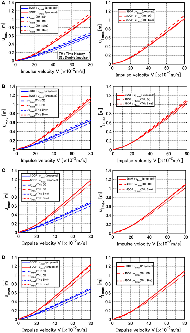
Figure 10. Comparison of maximum deformations of 10-story model for the proposed method, time-history response analysis under double impulse and time-history response analysis under corresponding one-cycle sine wave, (A) Rigid ground, (B) Soil type 1, (C) Soil type 2, (D) Soil type 3.
The left figure in Figure 10B shows the comparison of the maximum deformations (after the first impulse and after the second impulse) of the models on the ground of type 1. Furthermore, the right figure in Figure 10B presents the comparison of the maximum deformations (after the first impulse and after the second impulse) in the base-isolation story of the model on the ground of type 1. It can be observed that the proposed model reduction into the SDOF model and the closed-form expressions in the previous paper (Akehashi et al., 2018) are sufficiently accurate in the evaluation of both the total response and the response in the base-isolation story.
Figures 10C,D illustrate the corresponding comparison for the models on the ground of type 2, 3. It can be seen that the proposed model reduction into the SDOF model and the closed-form expressions in the previous paper (Akehashi et al., 2018) are accurate enough for the models on rather soft grounds.
Figures 11A–D show the comparisons for the model reduced from a 20-story building on the rigid ground and the grounds of type 1–3. It can be seen that the same tendency as in the model of 10 story exists.
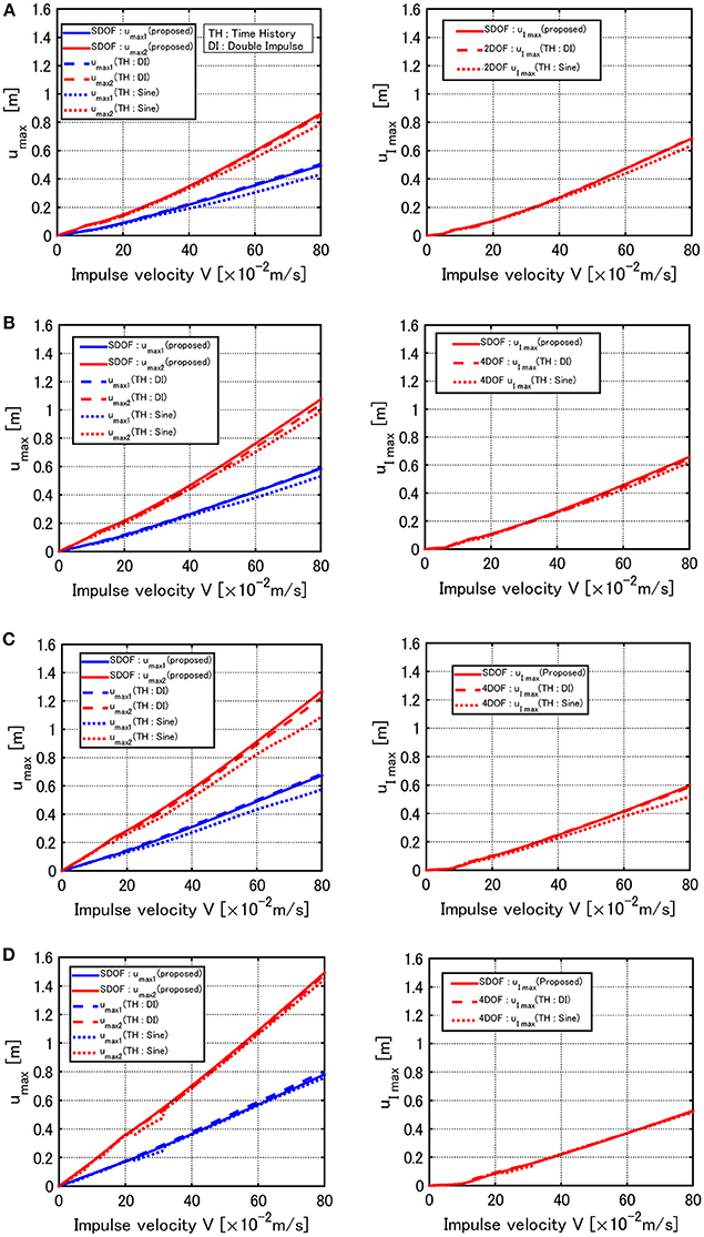
Figure 11. Comparison of maximum deformations of 20-story model for the proposed method, time-history response analysis under double impulse and time-history response analysis under corresponding one-cycle sine wave, (A) Rigid ground, (B) Soil type 1, (C) Soil type 2, (D) Soil type 3.
Applicability of Proposed Theory to Actual Near-Fault Ground Motion
It seems important to investigate the applicability of the present theory to actual recorded pulse-type ground motions.
Consider a representative pulse-type ground motion, i.e., the Rinaldi station fault-normal component, shown in Figure 1A, during the Northridge earthquake in 1994. Since the ground motion is fixed, the structural models are varied, i.e., ω1 and dy in Vy = ω1dy are varied. Figure 12 shows the maximum amplitude of deformation for the recorded ground motion and the corresponding proposed one. The sum (umax1+umax2)/dy of the both amplitudes is plotted here. The 10-story model on Soil types 1, 3 and the 20-story model on Soil type 1 and 3 introduced in the previous section are dealt with. The second stiffness ratios α of the equivalent SDOF model are 0.146, 0.202, 0.423, 0.649 for the 10-story model on Soil type 1 and 3 and the 20-story model on Soil types 1, 3, respectively. The damping ratios of the equivalent SDOF model are 0.0135, 0.0088, 0.0058, 0.0024 for the 10-story model on Soil types 1, 3 and the 20-story model on Soil types 1, 3, respectively. As stated before, since the initial velocity V is determined in Figure 1A, Vy is changed here. This procedure is similar to the well-known elastic-plastic response spectrum developed in 1960-1970. The solid line is obtained by changing Vy for the specified V using the method for the double impulse and the dotted line is drawn by conducting the nonlinear time-history response analysis on each model with varied Vy under the recorded ground motion. It can be observed that, although a slight difference can be seen in the large range of V/Vy, the result by the proposed method is a fairly good approximate of the result by the recorded pulse-type ground motion.
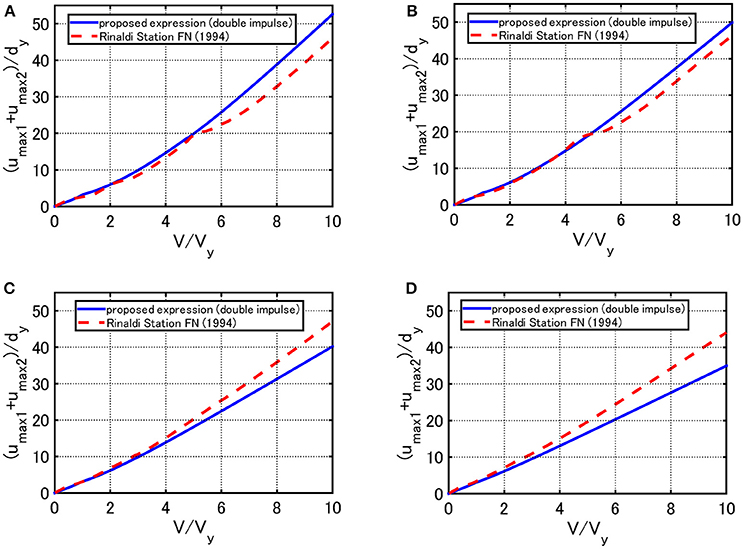
Figure 12. Maximum amplitude of deformation for the recorded ground motion (Rinaldi station fault-normal component) and the proposed one: (A) 10-story model (Soil type 1), (B) 10-story model (Soil type 3), (C) 20-story model (Soil type 1), (D) 20-story model (Soil type 3).
Conclusions
The critical nonlinear response has been investigated for a base-isolated building on ground under a double impulse as a substitute for near-fault earthquake ground motions. The complicated model of the nonlinear base-isolated building considering soil-structure interaction was first modeled as a two-degree-of-freedom (2DOF) system (SDOF superstructure and base-isolation story) on a swaying-rocking spring-dashpot system. Then the 2DOF system on a swaying-rocking spring-dashpot system was transformed into an SDOF system on a swaying-rocking spring-dashpot system by neglecting the mass on the base-isolation story. Finally the SDOF system on a swaying-rocking spring-dashpot system was further transformed into an SDOF system by neglecting the mass and moment of inertia of the base mat. Since an explicit expression had been derived on the maximum elastic-plastic response of an SDOF damped structure with bilinear hysteresis under the “critical double impulse input,” this expression was applied to the finally transformed SDOF system. The transformation of structural viscous damping in different elements is another new aspect in this paper. The conclusions may be summarized as follows.
(1) By deleting the degrees of freedom just above the base-isolation story and at the base mat, the complicated model of the nonlinear base-isolated building considering soil-structure interaction can be transformed into an SDOF system. After the model transformation, the explicit expression on the critical maximum elastic-plastic response of the SDOF system derived in the previous paper can be used and the critical maximum elastic-plastic response in the base-isolation story can also be evaluated.
(2) The accuracy of the model transformation and the validity in the application of the previously derived expressions have been discussed. The comparison with the maximum deformation under the critical double impulse and the one-cycle sine wave (good representative of the main part of the near-fault ground motion) supports the validity of the proposed theory. For reliable comparison, the time-history analysis was introduced. It has been made clear that, once appropriate adjustment of the maximum Fourier amplitude is made, the double impulse can become a reasonable substitute for the one-cycle sine wave. Furthermore the maximum deformation subjected to a near-fault ground motion can be captured by the double impulse.
(3) Numerical examples demonstrated that the explicit expression on the critical maximum elastic-plastic response of the SDOF system derived in the previous paper can simulate the maximum response under the critical double impulse and the corresponding one-cycle sine wave within a good accuracy independent of the ground stiffness. While the proposed expression almost gives an upper bound of the time-history response under the double impulse and the corresponding one-cycle sine wave in 20-story models, it does not necessarily provide an upper bound of the response under the double impulse in 10-story models. However its discrepancy is small. In addition, the influence of the ground stiffness on the critical maximum deformation at the base-isolation story is small.
(4) The expression on the critical maximum elastic-plastic response of the SDOF system under the double impulse can simulate the maximum response under recorded ground motions once the main part of the recorded ground motion is transformed into the double impulse. In this simulation, the yield deformation and the natural circular frequency are changed because the recorded ground motion is fixed.
Author Contributions
HA formulated the problem, conducted the computation, and wrote the paper. KK formulated the problem and wrote the paper. KF helped the computation and wrote the paper. IT supervised the research and wrote the paper.
Conflict of Interest Statement
The authors declare that the research was conducted in the absence of any commercial or financial relationships that could be construed as a potential conflict of interest.
Acknowledgments
Part of the present work is supported by KAKENHI of Japan Society for the Promotion of Science (No.15H04079, 17J00407, 17K18922). This support is greatly appreciated.
References
Abrahamson, N., Ashford, S., Elgamal, A., Kramer, S., Seible, F., and Somerville, P. (1998). in Proc. of the 1st PEER Workshop on Characterization of Special Source Effects (San Diego, CA: Pacific Earthquake Engineering Research Center, University of California).
Akehashi, H., Kojima, K., and Takewaki, I. (2018). Critical response of SDOF damped bilinear hysteretic system under double impulse as substitute for near-fault ground motion. Front. Built Environ. Specia. Sect. Earthq. Eng. 4:5. doi: 10.3389/fbuil.2018.00005
Alavi, B., and Krawinkler, H. (2004). Behaviour of moment resisting frame structures subjected to near-fault ground motions. Earthq. Eng. Struct. Dyn. 33, 687–706. doi: 10.1002/eqe.369
Bertero, V. V., Mahin, S. A., and Herrera, R. A. (1978). Aseismic design implications of near-fault San Fernando earthquake records. Earthq. Eng. Struct. Dyn. 6, 31–42. doi: 10.1002/eqe.4290060105
Caughey, T. K. (1960a). Sinusoidal excitation of a system with bilinear hysteresis. J. Appl. Mech. 27, 640–643. doi: 10.1115/1.3644075
Caughey, T. K. (1960b). Random excitation of a system with bilinear hysteresis. J. Appl. Mech. 27, 649–652. doi: 10.1115/1.3644077
Di Sarno, L., Elnashai, A. S., and Manfredi, G. (2011). Assessment of RC columns subjected to horizontal and vertical ground motions recorded during the 2009 L'Aquila (Italy) earthquake. Eng. Struct. 33, 1514–1535. doi: 10.1016/j.engstruct.2011.01.023
Drenick, R. F. (1970). Model-free design of aseismic structures. J. Eng. Mech. Div. ASCE 96, 483–493.
Elnashai, A. S., and Di Sarno, L. (2008). Fundamentals of Earthquake Engineering. Chichester: Wiley and Sons.
Hall, J. F., Heaton, T. H., Halling, M. W., and Wald, D. J. (1995). Near-source ground motion and its effects on flexible buildings. Earthq. Spectra 11, 569–605. doi: 10.1193/1.1585828
Iwan, W. D. (1961). The Dynamic Response of Bilinear Hysteretic Systems. Ph.D. thesis, California Institute of Technology, Pasadena.
Iwan, W. D. (1965a). “The dynamic response of the one-degree-of-freedom bilinear hysteretic system,” in Proceedings of the Third World Conference on Earthquake Engineering (Wellington).
Iwan, W. D. (1965b). The steady-state response of a two-degree-of-freedom bilinear hysteretic system. J. Appl. Mech. 32, 151–156. doi: 10.1115/1.3625711
Kalkan, E., and Kunnath, S. K. (2006). Effects of fling step and forward directivity on seismic response of buildings. Earthq. Spectra 22, 367–390. doi: 10.1193/1.2192560
Khaloo, A. R., Khosravi, H., and Hamidi Jamnani, H. (2015). Nonlinear interstory drift contours for idealized forward directivity pulses using “modified fish-bone” models. Adv Struct. Eng. 18, 603–627. doi: 10.1260/1369-4332.18.5.603
Kojima, K., Saotome, Y., and Takewaki, I. (2017). Critical earthquake response of a SDOF elastic-perfectly plastic model with viscous damping under double impulse as a substitute of near-fault ground motion. J. Struct. Constr. Eng. AIJ 735, 643–652 (in Japanese). doi: 10.3130/aijs.82.643
Kojima, K., and Takewaki, I. (2015a). Critical earthquake response of elastic-plastic structures under near-fault ground motions (part 1: fling-step input). Front. Built Environ. 1:12. doi: 10.3389/fbuil.2015.00012
Kojima, K., and Takewaki, I. (2015b). Critical earthquake response of elastic-plastic structures under near-fault ground motions (part 2: forward-directivity input). Front. Built Environ. 1:13. doi: 10.3389/fbuil.2015.00013
Kojima, K., and Takewaki, I. (2015c). Critical input and response of elastic-plastic structures under long-duration earthquake ground motions. Front. Built Environ. 1:15. doi: 10.3389/fbuil.2015.00015
Kojima, K., and Takewaki, I. (2016). Closed-form critical earthquake response of elastic-plastic structures with bilinear hysteresis under near-fault ground motions. J. Struct. Constr. Eng. AIJ 726, 1209–1219. doi: 10.3130/aijs.81.1209
Liu, C.-S. (2000). The steady loops of SDOF perfectly elastoplastic structures under sinusoidal loadings. J. Mar. Sci. Technol. 8, 50–60.
Luco, J. E. (2014). Effects of soil-structure interaction on seismic base isolation. Soil Dyn. Earthq. Eng. 66, 67–177. doi: 10.1016/j.soildyn.2014.05.007
Makris, N., and Black, C. J. (2004). Dimensional analysis of rigid-plastic and elastoplastic structures under pulse-type excitations. J. Eng. Mech. ASCE 130, 1006–1018. doi: 10.1061/(ASCE)0733-9399(2004)130:9(1006)
Mavroeidis, G. P., Dong, G., and Papageorgiou, A. S. (2004). Near-fault ground motions, and the response of elastic and inelastic single-degree-freedom (SDOF) systems. Earthq. Eng. Struct. Dyn. 33, 1023–1049. doi: 10.1002/eqe.391
Mavroeidis, G. P., and Papageorgiou, A. S. (2003). A mathematical representation of near-fault ground motions. Bull. Seism. Soc. Am. 93, 1099–1131. doi: 10.1785/0120020100
Parmelee, R. A. (1970). “The influence of foundation parameters on the seismic response of interaction systems,” in Proceedings of the 3rd Japan Earthq Earthquake Engineering Symposium, Vol. 3 (Tokyo), 49–56.
Roberts, J. B., and Spanos, P. D. (1990). Random Vibration and Statistical Linearization. New York, NY: Wiley.
Sasani, M., and Bertero, V. V. (2000). “Importance of severe pulse-type ground motions in performance-based engineering: historical and critical review,” in Proceedings of the Twelfth World Conference on Earthquake Engineering (Auckland).
Takewaki, I. (2007). Critical Excitation Methods in Earthquake Engineering, 2nd Edn. London: Elsevier.
Keywords: critical excitation, soil-structure interaction, base-isolated building, elastic-plastic response, bilinear hysteresis, near-fault ground motion, resonance
Citation: Akehashi H, Kojima K, Fujita K and Takewaki I (2018) Critical Response of Nonlinear Base-Isolated Building Considering Soil-Structure Interaction Under Double Impulse as Substitute for Near-Fault Ground Motion. Front. Built Environ. 4:34. doi: 10.3389/fbuil.2018.00034
Received: 21 April 2018; Accepted: 19 June 2018;
Published: 17 July 2018.
Edited by:
Solomon Tesfamariam, University of British Columbia, CanadaCopyright © 2018 Akehashi, Kojima, Fujita and Takewaki. This is an open-access article distributed under the terms of the Creative Commons Attribution License (CC BY). The use, distribution or reproduction in other forums is permitted, provided the original author(s) and the copyright owner(s) are credited and that the original publication in this journal is cited, in accordance with accepted academic practice. No use, distribution or reproduction is permitted which does not comply with these terms.
*Correspondence: Izuru Takewaki, dGFrZXdha2lAYXJjaGkua3lvdG8tdS5hYy5qcA==