 Magnus Larsson
 Magnus Wålinder
- EnWoBio-Engineered Wood and Biobased Building Materials Laboratory, Department of Civil and Architectural Engineering, School of Architecture and the Built Environment, KTH Royal Institute of Technology, Stockholm, Sweden
This paper investigates ways in which weathering-related site conditions can be allowed to inform the design process in order to improve a building's geometry and performance. Providing a building design with the capacity to remember past experiences and anticipate future events can provide substantial gains to the architectural configuration and engineering of a timber façade. A new theory of architecture is outlined based on recent “teleodynamic” theories—a hypothesis about the way far-from-equilibrium systems interact and combine to produce emergent patterns. The proposed explanation considers nested levels of thermodynamic systems applied to an architectural context: “homeodynamic” operations that involve equilibration and dissipation of constraint combine to produce self-organising “morphodynamic” procedures that amplify and regularise site-specific constraining data streams. A teleodynamic design reconstitutes itself by combining morphodynamic processes so as to optimise its relationship to the past, present, and future. A novel teleodynamic design tool called Contextual Optimisation Workspace (COW) is assembled within the Grasshopper visual programming environment. The tool is used to carry out four experiments that combine to produce the teleodynamic design of an urban wooden façade, exemplifying an alternative framework for the design of wood-based structures. The first experiment investigates a variegated grid combining two distinct subdivision methods (an orthogonal grid and a Voronoi tessellation), transmuting one system into another. The second and third experiments focus on durability aspects of a wooden façade and devise strategies for how the effects of photochemical degradation and wetting due to driving rain might be minimised using the COW tool. The fourth experiment optimises the building for daylight based on an illuminance simulation. Using simulation and anticipation to add the advantages of site- and time-specific data streams as a design strategy can effectively suspend an algorithm-driven design iteration in time and space in order to allow it to be parametrically influenced by past or future events such as unique site and project conditions. The COW tool can be used to produce such teleodynamic designs.
Introduction
This paper is an attempt to outline the beginnings of a new “teleodynamic” theory of architecture and engineering. Teleodynamics is a recent hypothesis about the way far-from-equilibrium systems interact and combine to produce emergent patterns. Turning this theory into practice, a novel design tool is assembled from existing software parts. The tool is then put to the test through four experiments that seek to prove its concept while optimising the façade design of the EnWoBio pavilion, a prototype structure planned to be constructed on campus at the KTH Royal Institute of Technology in Stockholm and unveiled in 2019. The pavilion will predominantly utilise bio-based materials, and the exercise below seeks to improve the efficiency of its exterior “skin” by using the best possible material components at optimal positions across the façade.
In the first experiment, two different grid systems are manipulated and merged together to define the building's envelope. The next three experiments seek to populate the outer surface of this envelope with four types of engineered wood elements carrying different properties, in an attempt to position the right material in the right place and achieve a set of predefined goals unique to the project at hand. A concluding discussion attempts to elucidate how such a paradigm-shifting theoretical framework and the design operations it supports allow for algorithmic design iterations to be influenced by past and future events, while considering possibilities for future studies.
This article has two primary objectives. The first is to delineate a new framework for an alternative theory of wood-based architecture and timber engineering based on recent speculations (primarily within the field of neuroanthropology) about teleodynamic processes (Deacon, 2012). The second is to show how a teleodynamically anticipatory design tool can be specifically used to engineer certain aspects of a timber structure.
To the best of the authors' knowledge, the present paper is the first ever to suggest that architecture and engineering can benefit from a theoretical framework based on the teleodynamic paradigm. Of principal interest here is the outlining of an initial conceptual foundation for such a novel theory. While example outcomes of the implementation of a teleodynamic design system are cited below to illustrate the processes involved, the results are highly generalised. Obtaining more precise values through actual optimisation operations will be the subject of future investigations.
The overall hypothesis examined is (1) that a teleodynamic strategy can be successfully and beneficially incorporated as part of a general architectural/engineering multiple-objective optimisation process, (2) that it can inform the decision-making process in surprising and unconventional ways to yield creative and significant results, and (3) that such a design procedure might uncover fertile ground for future studies.
To simplify the experimental process and the analysis of the results obtained at this proof-of-concept stage, the trials below were designed so that they can be repeated using actual multiple-objective optimisation (MOO) processes, but without invoking actual MOO procedures. (Instead, the experiments are carried out “manually” using parametric definitions). This postpones the time-consuming process of analysing substantially larger outputs of alternative design iterations, while still achieving the principle goal of proving the COW concept.
The investigation is limited to the teleodynamic design of a building envelope and the teleodynamic panelisation of this envelope's façade when simulated and optimised for UV radiation, illuminance, and anticipated wetting (through rainfall). Several factors that will obviously need to be considered in a final real-life scenario have been deliberately left out, including structural considerations, potential “green building” benefits such as passive solar heating, programmatic concerns, aesthetic intentions, legal and financial constraints, and so on.
Method
Teleodynamic Architecture
Constructing an avant-garde methodological framework based on an interdisciplinary appropriation of the recent term teleodynamics (Deacon, 2012) is one way to apply ideas of simulation and optimisation to the fields of engineering and architecture.
In his extensive and formative study, biological anthropologist Terrence Deacon attempts to fuse a wide range of topics—from biosemiotics via philosophy through to the underlying mechanisms of life itself—into a grand theory of emergent dynamics. Deacon's thesis aims to explain “ententional” phenomena: concepts such as purpose, meaning, function, and intention that refer to (“are about”) something that is not present. Critic Mads Solberg has described the model as “a three-tiered process hierarchy describing how dynamical processes like meaning, subjectivity, self and sentience are organized in relation to “possibilities not realized” (Solberg, 2014).
Teleodynamics can be visualised as a procedural hierarchy constructed from nested levels of thermodynamic systems. At the basic level we find homeodynamic systems, which involve the simple “equilibration and dissipation of constraint” (Solberg, 2014). These systems combine to produce more complex morphodynamic processes (one level up in the hierarchy) that “amplify and regularise constraint” (Solberg, 2014). Morphodynamic systems in turn combine to produce teleodynamic systems, a “dynamical form of organization that promotes its own persistence and maintenance by modifying this dynamics to more effectively utilize supportive extrinsic conditions” (Deacon, 2012, p. 270).
Homeodynamics, morphodynamics, and teleodynamics are “shifts in causal tendencies,” characterised by Deacon as “processes of organization that yield higher-level, stable and more complex dynamic patterns from lower-level dynamics (i.e., morphodynamics is formed from homeodynamics; teleodynamics is formed from morphodynamics)” (Pryor, 2015). The authors intend to investigate further the philosophical/theoretical aspects of such a teleodynamic architecture in a planned paper, and will focus here primarily on some pragmatic applications of this new paradigm.
MOO
Design processes are per definition decision-making processes, and decision making itself is “the process of selecting a possible course of action from all the available alternatives” (Hwang and Masud, 1979). In most situations, and certainly throughout the decision making that defines an architectural or engineering design process, “the multiplicity of criteria for judging the alternatives is pervasive,” that is, the decision maker “wants to attain more than one objective or goal in selecting the course of action while satisfying the constraints dictated by environment, processes, and resources” (Hwang and Masud, 1979). Multiple-objective optimisation (MOO) is a technique used within the field of multiple-criteria decision making as a response to such situations.
It is important to note that MOO isn't necessarily capable of providing a single solution that simultaneously optimises for all objectives, but rather a (possibly infinite) number of compromises between conflicting objective functions. These are called Pareto optimal solutions, and are considered equally good until a subjective preference (such as the designer's desires, or a list of preconceived targets) is added to the system (Ehrgott, 2005).
COW
Our teleodynamic design system seeks to improve architectural and engineering schemes through MOO. We call this system COW (Contextual Optimisation Workspace), and have constructed it as a prototypical application within the Grasshopper visual programming language and environment, an integral part of the Rhinoceros 3D computer-aided design (CAD) application (Rutten, 2007; Robert McNeel and Associates, 2014). Grasshopper is primarily used to construct generative algorithms by dragging components (snippets of code) onto a canvas and connecting their outputs to the inputs of other components. A work in progress, the COW prototype consists of a workspace in Grasshopper and a set of “user objects”—algorithmic components scripted specifically for use within the COW “application.”
The present version of COW features eight groups of such user object components. These mechanisms are connected (theoretically in any order) within the central Fitness area of the workspace, where the multiple-objective optimisations take place (Figure 1). While eventually any component can be attached to any other, at this early development stage, COW operates on a preconceived sequential combination of components from the different COW groups: a Frame is constructed, a Field delimited, Flows defined, a Form drafted, Functions implemented, Forces applied, a Façade constructed, and Future values recorded and logged. Furthermore, COW collects three modes of output: information (data), 2D representations (drawings), and 3D representations (digital models), while also providing support for the creation of physical 3D representations (scale models). We will now discuss each group in further detail.
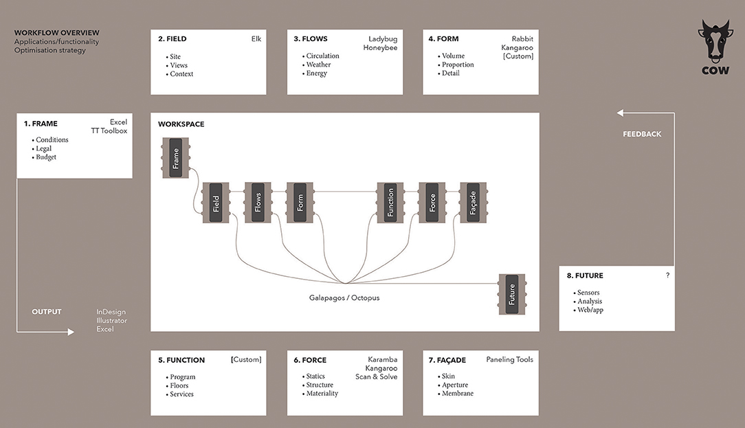
Figure 1. The COW (Contextual Optimisation Workflow) system.
The Frame group features components that gather relevant data to set the stage for all subsequent combinations of components by providing a constraining framework that delimits the boundary conditions within which those components are allowed to operate. Such data might for instance include legal restrictions, planning demands, budgetary constraints, defined material systems, life cycle analysis (LCA)-based requirements, time- and scheduling-related limitations, sustainability targets, market analysis specifications, and so on. The data is logged in Excel (Microsoft., 1985), and fed to the succeeding components through an Excel listener component. The Frame can be said to control all project-specific data up until the point at which a specific site is decided upon.
The Field group provides a particular site that anchors the project in the physical world. While all COW components are largely based on previous work by the (informal) community of Grasshopper developers, Field borrows extensively from Timothy Logan's Elk component, which generates topographies and street maps using data from OpenStreetMap.org as well as Shuttle Radar Topography Mission (SRTM) data from the NASA/Jet Propulsion Laboratory (Logan, 2013). The outcome is a wide array of site-specific data ranging from simple coordinates and cardinal directions through to building footprints and road networks. Components within this group also support different site analysis methods, including the creation of grids, zones, and vector fields.
The Flow group adds data that corresponds to flows running through the demarcated site—fluxes such as the circulation of people, the movements of vehicles, motion through different infrastructural networks, as well as past and future local weather conditions. Simulations allow for experimentation using different potential scenarios, and parametrically controlled points and curves are added to the model to be used as constraining attractors and repellers in subsequent modelling.
The Form group unsurprisingly holds form-generating components. The group's components model forms in many different ways. One strategy uses an initial volumetric boundary, such as the maximum allowable building envelope, or the structure's solar envelope (Knowles, 2003). Another employs formal “seeds” (form-generating concepts such as the stacking of boxes or the packing of spheres) to configure shapes. The components making up this group are likely to be uniquely composed (scripted) for each individual scheme, as the formal aspects added at this stage make up the main architectural contribution to the project in terms of aesthetic vision, formal direction, and visual impact.
The Function group collects components that can be used to add programmatic features to the design and adjust it in accordance with such characteristics. Here we find means to control the structure so as to make it accommodate different architectural programs (support the events taking place within and around the structure), adjust its internal vertical subdivision into floors, optimise for accessibility, and so on.
The Force group gathers classical engineering aspects into a set of components that deal with the forces being applied to the structure, from the outside as well as from within. Components that optimise the structural engineering of the design and its resistance to different kinds of loads and activities.
The Façade group contributes components that are exclusively aimed at designing and adjusting the structure's skin, including its fenestration. Some components in this set overlap with those in the Force group, as the control of functions such as ventilation and lighting are largely dependent on the performance of the skin.
The Future group consists of components that can be used to track the performance of the (virtual or actualised) structure over time. It also allows for a sort of manifold construction, whereby the final physically built and/or digitally modelled design can be viewed as a benchmark structure made (through simulations) to not only adhere to and withstand the actual forces applied to the built structure, but equally well to be subjected to other forces, other scenarios, other events.
Over time, such a simultaneous construction of both a physical model (the final building itself, equipped with data trackers and sensors) and a plurality of digital structures “living” under different conditions would result in an archive of data that could be referenced and invoked in future designs, thus creating a sort of external “memory,” or “experience” for future COW structures to draw upon. This notion of the final building as a “built-model” (Ansari, 2013) with a number of coexisting “digital doubles” holds another potential: that of analysing the “noise” between the simulation and the real-world structure. It is likely within this realm that further optimisations are to be more easily found.
COW connects the mechanisms collected within the above eight groups and then performs multiple-objective optimisations—using either David Rutten's evolutionary solver, Galapagos (bundled with Grasshopper), or the Octopus plug-in (Vierlinger, 2012)—to achieve constructive compromises between the conflicting desires that the design team wishes to negotiate. Emotion as well as efficiency, embodied energy as well as economic potential are all examples of desires, some more easily quantifiable than others, that can be used to drive such an evolutionary system towards a Pareto-efficient sub set (one allocated so as to make it impossible to improve on any preference criterion without worsening at least one other such criterion) from which to make the final choice.
This is not the first MOO-based tool for architectural and engineering design and research. Many predecessors exist, such as the applications GENE_ARCH, Mobo, and Opt-E-Plus. For a good review of computational optimisation methods within the field, see (Evins, 2013). A very helpful overview of optimisation programs applied to building performance optimisation is shown in (Nguyen et al., 2014), a paper that also features an interesting graph showing the increased number of optimisation studies in building science, a trend that seems to have taken off in earnest around 2005. However, since no existing tool appeared to support the teleodynamic methodology we had in mind, we decided to build our own.
One important aspect of that methodology is a concept that has been part of the transdisciplinary cybernetic tradition at least since the publication of the paper “Behavior, Purpose and Teleology” (Rosenblueth et al., 1943). The system should “exhibit control” and therefore be “goal orientated, teleological or purposive”—it should “have a desired state, and the act of control brings [it] towards that state” (Glanville, 2004). However, as Glanville points out in his historical account (Glanville, 2004), roughly coinciding with Margaret Mead's seminal 1968 paper Cybernetics of Cybernetics (Mead, 1968), a transition occurred where cybernetics evolved from first-order cybernetics (about observed systems) to second-order cybernetics (about observing systems).
In second-order cybernetics, the observer “is understood to be both within the system being described and affected by it” (Glanville, 2004). In a valid description of the COW system, the “observer” should be substituted for “member of the design team.” A client, an architect, an engineer, and a sustainability consultant might have quite differing ambitions for the project at hand. A tool such as COW can allow them to find common ground in a series of weighted targets that can influence each other and be updated at any point throughout the design process, thereby generating the ability of the system to adapt continuously over time.
Results and Analysis
Methodological Experiments and Results
As the starting point for an impending in-depth investigation of the possibilities of teleodynamic architecture and engineering, the present study focused on developing the first version of the COW system and understanding its theoretical ramifications.
Using COW, four experiments were carried out that together begin to define the design of our prototype building's wooden façade. The process allowed different timber panel types to be applied to the building envelope like a quilt to maximise its material potential in the given context using operations driven by simulations that use data from the actual site in question.
The first experiment investigated how a combination of algorithms can create a variegated grid that forms a single, surface-defining lattice. Two distinct subdivision methods (a regular orthogonal grid and a Voronoi tessellation grid) are combined, seamlessly transmuting one system into the other.
The two following experiments focused on durability aspects. The second experiment investigated a strategy for how photochemical degradation can be minimised through the COW system's multiple-objective optimisations. A simulation of solar radiation revealed what cells within the building envelope lattice are most likely to be affected by the sun, then turned this “problem” into a potential by assigning panels capable of harvesting photovoltaic energy to those surfaces.
As a measure against wetting due to driving rain, the third experiment instead assigned a particular panel material to surfaces within a certain angular span relative to the ground datum.
The fourth experiment used an illuminance simulation to control fenestration while optimising the daylight factor inside the building.
The resulting final material subdivision of the façade is shown in (Figure 2). The panelisation strategy is based on four cross-laminated timber (CLT)-based materials with differing levels of durability. All four panel types are hypothetical. Panel A is the default element of the skin we are designing: a standard CLT panel with a top layer that has been pressure-treated with a preservative formulation to better withstand weather pressures. Panel B adds a photovoltaic surface layer to the CLT, for a novel hybrid element that harvests solar energy from the surfaces most highly exposed to photochemical radiation. Panel C adds a surface layer of acetylated wood to the CLT, for use in parts of the façade where water run-off is slow. Panel D adds a glass sheet glued onto a perforated CLT panel to produce a glazing element that allows light into and views out of the building while protecting the underlying wood. The panel types are illustrated in (Figure 3).
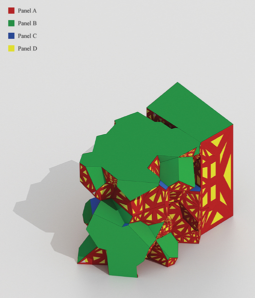
Figure 2. The final material subdivision of the façade.
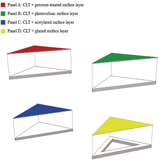
Figure 3. The four CLT-based building elements used in the experiments.
Experiment I: Volume
The first experimental stage investigated the teleodynamic design of the volumetric massing, or “global geometry,” of the EnWoBio pavilion. As opposed to the shape of the structure (its outline from a single perspectival point), an architectural massing volume denotes the structure's three-dimensional form (its “skin”).
User components are Grasshopper objects created by its community of users. They are stored locally on each user's computer, but can also be distributed. User components can be created straight from within the Grasshopper environment, and are much easier to produce than actual components, which call for programming using languages such as Visual Basic, C#, or Python.
Connecting such a user component (Field) developed specifically for the COW environment to the Grasshopper definition provided an overview of the site, which was found to encompass a roughly rectangular footprint of 50 × 80 m. Conversations with the division for spatial activities at the KTH campus suggested that it would be reasonable to use this footprint area in order to stay within the legally allowable boundary. As future simulations are not likely to return a perfectly rectangular footprint, an arbitrary polygonal building boundary was drawn within the given area confines. The footprint is angled at −23.56° to align with the primary site axis; its area is 339 m2, and its circumference 80 m (Figure 4). The boundary was extruded to a height of 15 m (roughly aligning with but not rising above the roofline of neighboring buildings) to obtain an initial massing volume of 5,081 m3 and a surface area of 1,538 m2 (Figure 5).
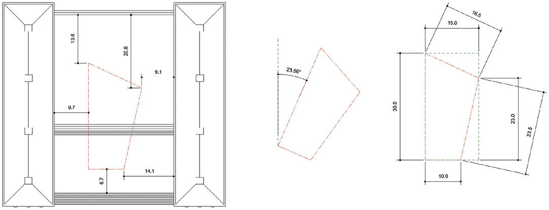
Figure 4. The arbitrary polygonal building boundary on site.
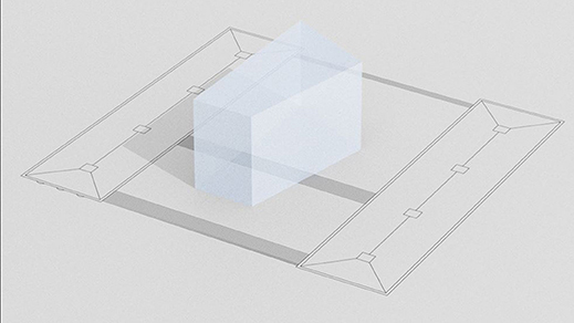
Figure 5. The initial massing volume on site.
The resolution of a geometry's subdivision has an obvious impact on its potential for optimisation. A seamless skin stretched across a fixed armature effectively lacks any optimisation capacity over and above changes afflicting the material of the skin itself. It might be possible to calibrate the inherent thermal mass of the material at certain points. The skin's relative translucency can perhaps be selectively changed. Its thickness can conceivably be allowed to change along a gradient across the surface length, or simply increase in certain areas. Maybe pockets can be created where other materials can be added (to produce a hybrid material). But the possibilities for further optimisations remain highly limited.
Subdivide this single skin into two skins, however, and it can of course feature two different sheet materials with distinct properties. With every further increase to the number of faces, the prospect of improving the performance of the building envelope through a strategic application of different materials accumulates. If the subdivision is not simply restricted to a structured grid, but also allows the implementation of an unstructured one—that is, if the subdivision's form is allowed to impact on the optimisation potential—the chances of achieving better results through optimisation processes are further improved.
In real-life scenarios, standardised material dimensions and cost implications are likely to influence the resulting variegated (hybrid) grid towards a more structured state. Simulation results and potential optimisation benefits are expected to work in the opposite direction, towards a more unstructured subdivison. In teleodynamic terms, the latter trajectory produces a more “orthograde” grid (veering towards the stable organisational equilibrium of chaos, or maximum entropy) while the former results in a more “contragrade” grid (veering towards the traditional architectural subdivision of a more symmetrical grid) (Pryor, 2015).
Such an orthograde/contragrade grid was achieved through the combination of two distinct subdivision methods: one based on a regular orthogonal grid, the other on a random Voronoi tessellation. The latter is “the partitioning of a plane with n points into convex polygons such that each polygon contains exactly one generating point and every point in a given polygon is closer to its generating point than to any other” (Voronoi, 1907; Weisstein, 2009) (Figure 6). Extended to three dimensions (as in the cellular geometry used here), an analogous construct would be soap bubbles in compression: place a cloud of points inside a box and proceed to blow a bubble around each point until the bubbles meet either each other or the edge of the box. The resulting space-covering tiling produced by the intersections of the bubbles form a three-dimensional Voronoi pattern (Gold, 1989).
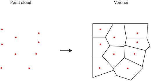
Figure 6. Voronoi tessellation.
If the point cloud that makes up a Voronoi tessellation's underlying set of cell nuclei is symmetrically ordered into a so-called Delone set (a decidedly well-spaced set of points), the resulting Voronoi cells will become highly regular. These space-filling polyhedra are called plesiohedra (Grünbaum and Shephard, 1980), and include such well-known crystal structures as the cube, hexagonal prism, and rhombic dodecahedron. We would still consider a plesiohedral tessellation to be contragrade. It is when the cell nuclei are randomly organised that the Voronoi becomes an orthograde tiling, as it is then driven by the internal geometry of the system itself rather than being “forced” by interactions with an extrinsic system (Deacon, 2012, p. 220–227).
A brep (“boundary representational object”) is a local geometrical representation that connects vertices, edges, and faces. COW's Voronoi Seed user component takes three input data: (1) The bounding geometry brep, defined by the initial massing volume, (2) a number of points (in this case 100), (3) a random seed value (in this case 1) for points insertion. The component outputs a final three-dimensional Voronoi geometry together with data about its surface area and volume. The brep is first turned into a bounding box, which is then used as a virtual container within which points can be pseudo-randomly dispersed. Around these points, a Voronoi structure is generated. A routine then culls the parts of Voronoi cells that lie outside the bounding box, producing the final cellular form.
That COW user component was combined with another, Threshold Curve, which uses the site boundary curve (the two-dimensional outline of the massing volume in the x/y plane—its footprint) as a starting point. This polyline is exploded into an ordered list of segments. Slider values allow for a parametrically controlled subdivision of these segments such that a “threshold curve” can be drawn between control points on opposing edge curves.
Lofting two surfaces between this subdividing threshold curve and the two edge curves at each end of the footprint, and then extruding those surfaces to the same height as our initial massing volume, produces an object that is seamlessly split into two different tessellations on each side of the threshold curve. On the “contragrade” side, the form is based on a regular cubic honeycomb tessellation, while on the “orthograde” side, the form follows the three-dimensional Voronoi tessellation (Figure 7). The threshold curve between the two states thus controls the relative degree of contragrade-ness vs. orthograde-ness exhibited by the resulting modified massing volume.
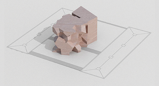
Figure 7. The modified massing volume and its seamless orthograde/contragrade tessellation.
While this article is not focused on evaluating biomimetic connections between the techniques used and examples found in biology, it seems sensible here to point out the theoretical similarity between such an architectural skin system capable of moving from orthograde to contragrade state, and the geometry of a biological skin system such as transitional epithelia.
Of the four basic types of animal tissue (the other three being connective tissue, muscle tissue, and nervous tissue), the epithelium tissue lines cavities and surfaces of organs and blood vessels. Transitional epithelia (sometimes referred to as urothelium as it almost exclusively lines the bladder, uretha, and ureters) are dome shaped and able to stretch.
In the presence of tensile forces, these special epithelial cells can change geometry. In its unstretched state, the organisation of the cell “grid” is “contragrade,” with cells being large, rounded, and “regularly” ordered into an essentially stratified cuboidal arrangement. In its stretched state, the organisation becomes “orthograde,” with cells pulled into a flatter, less symmetrical shape that makes for a stratified squamous arrangement (Hicks, 1965). While curvilinear rather than angular, this progressive transmutation from one system to another certainly bears a resemblance to the massing volume permutated through the process described above.
Ten different subdivision values were used to explore the result of different threshold curve positions, as planimetrically shown in (Figure 8). A highly articulated surface was deemed likely to provide more opportunities for iteration in the experiments to follow, and in the end a value of 3 (subdivisions of edge curves to produce threshold curve control points) was chosen as the most promising option. This decision was arrived at through intuitive rather than formal strategies or preconceived target values. As the optimum orientation for a passive house is generally assumed to be due south (Wang et al., 2013), the “orthograde” articulation was implemented predominantly toward the south side of the façade. In future experiments, the relative positioning of this threshold curve could and should of course itself be optimised so as to approach the most appropriate configuration of the resulting volume. The surface area for the new massing model is 2,556 m2, its volume 4,933 m3.
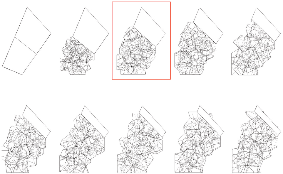
Figure 8. The ten different subdivision values used to explore the result of different positions for the threshold curve (chosen alternative highlighted in red).
How is this a teleodynamic form? The two grids that organise the articulation of the geometry can be viewed as self-simplifying morphodynamic systems as they amplify and regularise the constraints given by the algorithms and values that control them. One grid “attempts” to “pull” the form along an orthograde trajectory, towards the “natural” (“organic”) geometry of the random Voronoi tessellation; the other works in an opposing direction, “trying” to make it align with the contragrade “ordered” (“artificial”) geometry of the regular grid. The interaction between these two systems, guided by multiple-objective optimisations that adjust the iterative design process in response to constraints that hinge on ententional/anticipatory digital simulations, adds the teleodynamic dimension to the operation.
Experiment II: Photochemical Radiation
The building envelope is “one of the most significant contributors to the energy consumption and the comfort parameters of any building” (Aksamija, 2015). While a building's façade has historically been viewed mainly as a simple barrier between the indoors and the outdoors, this element is increasingly regarded as a building system with the potential to actively respond to the structure's external environment in order to significantly reduce the building's energy consumption. In most cases, the façade will affect the project's energy budget and the comfort of occupants more than any other system, and one proposed definition of high-performance sustainable façades reads “exterior enclosures that use the least possible amount of energy to maintain a comfortable interior environment, which promotes the health and productivity of the building's occupants” (Aksamija, 2013).
Regardless of their material composition, urban façades are under continuous attack from a wide array of physical, chemical, and biological agencies. While the threat of fire and the risk of fungal and insect attacks are by far the most important structural hazards to the durability of a wooden façade (Dinwoodie, 1981), the effects of photochemical degradation and wetting due to driving rain are significant aspects associated with the use of wood as a cladding material, and so the next two experiments focused on these two aspects.
The weathering of wood is largely a result of the material's inherent dimensional instability. Exposure of wood to ultraviolet (UV) light causes the formation of volatile products of degradation, as well as modifications to the chemical properties of the material itself (U. S. Forest Service, 1966). Sunlight will lighten the heartwood of most timbers (such as mahogany and oak), though it will also darken others (such as Rhodesian teak). The change in colour is very rapid, taking place in a matter of months, and is viewed as the first stage in the weathering process (Dinwoodie, 1981).
The combination of exposure to light energy together with subjection to rain and wind leads to a degrading mechanism that renders the timber silvery-grey. This effect is however not simply a (not necessarily negative) aesthetic matter, but a concern with regards to the resulting loss of surface integrity (Derbyshire and Miller, 1981; Derbyshire et al., 1995). The material deprivation leads first to a degradation (primarily by UV light) of the lignin, causing brittleness and a reduction in stress transfer capabilities, and second to a detrimental shortening of the chain length of the cellulose (primarily through energy from the visible part of the spectrum), leading to reductions in microfibril strength. The combined effect is an erosion of the cell wall and (in particular) the pit aperture and torus (Dinwoodie, 1981, p. 207). Once attacked, the cell walls act as “an efficient filter for those cells below and the rate of erosion from the combined effects of UV, light and rain is very slow indeed” (Dinwoodie, 1981).
That said, at least two reasons speak in favour of the utilisation of anti-weathering tactics with regards to photochemical radiation: (1) the continual threat of biological attack still makes proper weather protection a prudent strategy, and (2) a mitigatory strategy against radiation can easily be developed into a profitable strategy through the application of a photovoltaic wooden panel with the potential to not just alleviate material degradation but also harvest energy and improve the performance of the timber façade.
For the second experimental stage, a radiation simulation revealed what parts of the building envelope (on its actual site) are most likely to be affected by photochemical radiation. These are of course also the most beneficial areas from which to generate photovoltaic energy. The simulation made it possible to perform an initial material prioritisation and make an informed decision about which façade panels should ideally be assigned as Panel B (Figure 9). The UV and visible solar radiation reaching Earth's surface is limited to the range between 295 and 800 nm. Infrared radiation covers wavelengths between 800 and about 3,000 nm, and the radiation from 295 to 3,000 nm “comprises distinct ranges that affect weathering: UV radiation, visible light, and infrared radiation (IR)” (Williams, 2005).
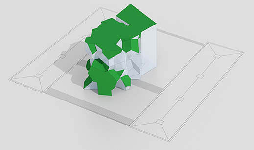
Figure 9. The building envelope faces identified as optimally carrying Panel B façade elements.
The simulation was carried out using the Ladybug plug-in for Grasshopper (Sadeghipour Roudsari and Pak, 2013a,b). An epw weather file for Arlanda (59.65 North latitude, 17.95 East longitude) was used. The true North was generated based on this location. In the interest of processing speed, the cumulative sky matrix parameter was set to generate a simple Tregenza sky (145 sky patches) rather than a more accurate Reinhart sky (580 sky patches). The analysis period was set to 09:00–17:00 between 1 January and 31 December. The shading of surrounding buildings was ignored. The analysis grid size was set to 0.1 m, as was the offset distance between the test point grid and the test geometry (in order to ensure that the radiation analysis was carried out for the geometry's exterior).
The simulation returned a total radiation (in one year) of 756,061 kWh. Using the Ladybug Mesh Selector component, a threshold value was used to cull any surface below the top 20 % of radiation values, returning a set of Panel B façade surfaces that receive between 700 and 1,000 kWh/m2 throughout the specified analysis period. The total radiation falling on these surfaces was 398,950 kWh. The total area of the Panel B surfaces was 474 m2. This represents the area shielded from photochemical degradation as well as the area used to obtain photovoltaic energy through the Panel B façade elements. Adding values for the total amount of energy that can potentially be harvested, as well as other parameters such as for instance material and implementation costs, maintenance savings, and levelised cost of electricity (IRENA Secretariat., 2012) could further support and focus the optimisation process in future implementations. An initial optimisation could for instance seek to minimise the surface area allocated to the Panel B elements while maximising the amount of solar energy obtained.
When connected to the volume-generating process described above, this radiation simulation-based strategy is a further example of how the combination of several interacting morphodynamic systems—the geometrical tug-of-war between the Voronoi tessellation and the regular grid being integrated with the analysis of its resulting faces' exposure to decay and potential for solar harvesting—synthesise to become a teleodynamic architectural system.
Experiment III: Water Runoff
We had subdivided the massing volume into its constituent grid faces, and initially assigned the basic preservation-treated material of Panel A to the entire envelope. A number of grid cells had been culled in order to allocate the solar energy-harvesting Panel B to a select set of surfaces based on their exposure to photochemical radiation. We were now left with a partial building envelope that could still be materially optimised further to maximise its performance.
A substantial part of the dimensional changes of wood that result from internal swelling and shrinking, as well as the decay and degradation of other properties of wood exposed to the elements, are caused by the skin being infiltrated by water. The next experimental stage analysed the remaining parts of the building envelope in order to find areas where another material—Panel C, with its water-repelling acetylated surface layer—could be systematically assigned to facets of the skin particularly susceptible to prolonged wetting.
It has been noted that all buildings, “whatever shortcomings they may have, are required to possess two fundamental characteristics. They should be structurally sound and they should exclude moisture” (Marsh, 1977). Timber façades typically have a moisture content range that is wider than accepted: “The minimum moisture content of around 10 % appears to be similar for all types of timber cladding and all species. The maximum appears to vary between species according to their fibre saturation point and is influenced by construction detailing and workmanship… it has been showed that the mean moisture content is all but irrelevant” (Davies, 2011).
A structure's surface geometry (for instance the design of horizontal and vertical projections, or the sculpting of individual façade panels) is the primary means of controlling the flow of runoff water, and uncontrolled runoff will produce uneven weathering of a building façade (Robinson and Baker, 1975). Rainwater runoff from building façades, however, is “a complex process governed by a wide range of urban, building, material and meteorological parameters,” and “despite research efforts spanning over almost a century, wind-driven rain and rainwater runoff are still very active research subjects” (Blocken et al., 2013). Indeed, in the process of preparing this paper, the authors identified a noticeable lack of discussion and data in the literature to aid the calculation of rainwater runoff for angled (non-vertical and non-horizontal relative to the ground datum) surfaces made from wood.
That is not an insignificant lacuna: the evolution of architecture as a morphological discipline indubitably hinges on advances in architectural geometry, and today's timber structures—designed through, enabled by, and constructed using cutting-edge computational technologies—are arguably at the forefront of this development (Menges et al., 2016; Weinand, 2016). This means contemporary avant-garde timber structures are likely to feature advanced geometries that depart from the orthogonal tradition on which most standard rainwater runoff calculations are based. If the wide range of parameters is what makes optimisation strategies based on (simulated) rainfall so complex, we could do worse for this initial experiment than focus on four key factors.
The first factor is the positioning of the structure in relation to other structures in its immediate vicinity (which may shield from or intensify the material degradation due to prolonged wetting), as well as its location on the planet, in relation to the distinctive local climate and the weather conditions it is likely to be subjected to. More specifically these include annual precipitation totals and other data that can be used to statistically project or determine the amount, momentum, intensity, and trajectories of condensation of atmospheric water vapour likely to fall on the structure under gravity. That is, historical records of rain and snow conditions for the unique site in question.
The typical weather on the present site (based on data from the weather station at the Arlanda Airport, Stockholm, Sweden, available at https://weatherspark.com/averages/28951/Stockholm-Sweden) is a reflection of the city's humid continental climate with warm summers and no dry season. There is a 50 % precipitation chance during the warm season (28 May−1 September), and in 53 % of those days this precipitation will be no worse than light rain. Such knowledge might well have a direct impact on the choice of surface elements in a material optimisation of the façade.
Closely related to the climate is the second factor: the impact of prevailing winds, in particular when it comes to risks associated with wind-driven rain (WDR). This is rain “given a horizontal velocity component by the wind and that falls obliquely,” a phenomenon considered to be “the most important moisture source affecting the performance of building façades” (Blocken and Carmeliet, 2004).
Several parameters need to be considered when calculating the quantity of WDR that might impinge on a façade. These include the structure's positioning and geometry, the topology of the environment in which it sits, and several specific climate-related variables including wind speeds, wind directions, the intensity of turbulence and rainfall, raindrop size distribution, and rain event duration. The large number and variable nature of these and other relevant parameters “make the quantification of WDR a highly complex problem. It is not surprising that despite research efforts spanning over almost a century, WDR is still an active research subject in building science and a lot of work remains to be done” (Blocken and Carmeliet, 2004, p. 1080).
The third factor is the contact angle hysteresis (CAH) of a drop of water hitting the surface of the building. This phenomenon can be intuitively understood if we focus on a single droplet of water resting on one of our façade panels. The raindrop is pulled down by gravity, while the counteraction of CAH keeps it in place, resulting in the drop becoming asymmetric without moving: “the top of the droplet becomes thin, with a low contact angle, while the bottom becomes thick, with a high contact angle” (Eral et al., 2013). Once the raindrop reaches a certain size, it will slide down the panel in an asymmetric fashion: the CAH is the difference between its front and back contact angles in the direction of the driving force (in this case gravity). These angles will, of course, change with the angle of the rain itself, as well as with the angle of the panel relative to the ground datum (Figure 10).
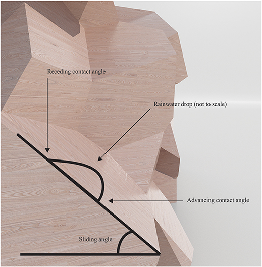
Figure 10. The principle of contact angle hysteresis.
The fourth and final of the primary factors considered here is to do with material properties. The roughness, moisture diffusion transition, and other wetting properties of the surface material used, as well as, potentially, its materially-embedded responsiveness (Reichert et al., 2015) of course have impacts on the structure's rainwater runoff capabilities. Untreated surface elements made from wood species such as maple, alder, and black locust are, for instance, likely to weather more slowly and be more durable following exposure to moisture (due to a lower decrease in contact angle). Surfaces made of, for instance, softwoods, oak, and poplar, on the other hand, will weather faster due to their higher hydrophilicity and corresponding decrease in contact angle (Oberhofnerová and Panek, 2016).
One effect of the acetylation process, which “replaces some of the hydroxyl groups on the cell wall polymers with bonded acetyl groups” (Rowell, 2005), is a reduction in the hygroscopicity of the wood and a decrease in its fibre saturation point. This counters the detrimental effects of the wood's exposure to moisture, and changes its properties in advantageous ways, including increases in dimensional stability, durability, and paint retention.
Given the above four primary factors impacting on the structure's capacity for shedding rainwater, it appears reasonable to assume that the building envelope's performance would benefit if any panel that is angled at ± 0–30° relative to the ground datum and that has not already been assigned the Panel B element (due to its exposure to radiation) were to be composed of the acetylated Panel C element. This assumption is of course rather generalized—the degree value could certainly be optimised further in future studies—but it constitutes a reasonable number that can be used as a starting point for future discussions in forthcoming experiments. Applying this value to the present structure identifies 11 surface panels as falling within the span specified, for a total surface area of 38 m2 (Figure 11).

Figure 11. The building envelope faces identified as optimally carrying Panel C façade elements.
Again, using the morphodynamic system that controls this degree interval as a boundary parameter within a multiple-objective optimisation that combines several such morphodynamic systems enables us to view the algorithmic “forces” that “pull” the angle values in opposite directions as being part of a teleodynamically controlled design. The contact angle hysteresis factor is probably the most clear-cut example of this, whereby the front angle of a droplet on the inclined surface (in the orthograde direction towards gravity) and the back angle (in the contragrade direction “pulling” against gravity) amplify and regularise the constraints given by their controlling algorithms.
Experiment IV: Illuminance and Fenestration
The initial three experiment stages described above yielded a process capable of providing a materially optimised building skin with regards to volume, radiation, and water runoff–but arguably they did not yet provide us with an architectural building envelope. This calls for at least one added functionality: a component that brings light and air to the interior spaces and allows for views of the outdoor scenery while keeping the thermal properties of the resulting edifice at acceptable levels.
Staying with the skin metaphor, we need a series of strategically positioned pores. Apertures capable of supplying sufficient amounts of daylight while limiting the building's solar heat gain, the often problematic increase in temperature resulting from solar radiation. The fourth and final experiment introduces such a context-driven fenestration strategy that optimises perforations in the building envelope and assigns a fourth material, the perforated CLT panel topped with a glass sheet layer that composes Panel D, to the orifices produced.
Basing an architectural design on a structure's alignment with the sun's path across the sky relative to the site in question is certainly not a new idea. The huge stones and embanked avenue that make up the main features of the prehistoric Stonehenge monument in the UK are famously positioned so that they line up with the sunset of the winter solstice and the opposing sunrise of the summer solstice along a north-east/south-west axis (Johnson, 2008). Experts still argue over the intentionality behind this design, with some maintaining that the monument was built on a natural ice age landform, which just happens to be on the solstice axis (Alberge, 2013). The history of architecture is ripe with solar-based constructions: similar alignments of structures and urban plans with solar events and phenomena have suggested the presence of advanced cultures at prominent historical sites including Machu Picchu, Abu Simbel, and Chaco Canyon. As a result of their religious beliefs, the ancient Aztecs orientated entire cities based on the directions from which the sun would rise (Aguilar-Moreno, 2007).
There are several contemporary additions to this tradition of solar-based designs that may be viewed as precedents to the illuminance optimisation discussed here. Steven Holl's (2007) Sliced Porosity Block housing scheme for Chengdu, China, takes its shape “from its distribution of natural light. The required minimum sunlight exposures to the surrounding urban fabric prescribe precise geometric angles that slice the exoskeletal concrete frame of the structure” (Steven Holl Architects, 20121). Other examples of architectural designs based on the sun's path across the sky include several designs by Studio Gang Architects, such as the Solar Carve office tower currently under construction in New York. The studio's residential tower in Chicago, Solstice on the Park (also under construction), features a woven glass curtain wall that is angled at 71 degrees in response to the city's latitude, to allow for passive solar warming in winter while reducing air conditioning needs in summer (Studio Gang Architects, 2017).
Having the sun illuminate an interior with natural daylight is a common strategy to enhance the visual comfort conditions for building occupants and reduce the overall energy use of a building. Factors that might impact on the designers' attempts to improve the temporal and spatial availability of daylight in an architectural structure include the massing and orientation of a building (and its façades), the fenestration strategy, and the properties of the materials used. Particular conditions unique to the site, weather aspects, the program of the building, and the more or less well-defined desires of its users may also have an influence.
Solar gains and visual comfort can be further improved and optimised using a range of widely available commercial products including shading devices, glare-mitigating light-diffusing panels, and daylighting elements that reflect incoming daylight deeper into the interior—over and above electric lighting and shading control systems.
Daylight performance targets are ideally identified at the outset of a project to guide the design while allowing for the weighted comparison of different daylight design options in terms of, for instance, cost versus predicted performance. The method employed here is a simplified version of this strategy. To rigorously analyse the opportunities of using natural daylight as an operative parameter in the multiple-objective optimisations-based methodology of COW, we need to first run simulations to estimate the physical amount of daylight available on the site and in the building. Those results can then be converted into daylight performance measures, which are finally interpreted and used to make and evaluate automated design decisions that control the final geometry of the structure.
Using the remaining facets of the mesh that defines the building envelope as our test analysis surface, we simulated the illuminance values at the surface for office hours (09:00 to 17:00) throughout the entire year (as to cover both the winter and summer seasons). A daylight simulation program can either calculate the amount of daylight “under selected sky conditions (static simulation) or during the course of the whole year (dynamic simulation)” (Reinhart, 2006). The range values used were 300–4,000 lx (generally viewed as the minimum amount needed for visibility and the lower threshold for glare issues, respectively (Reinhart, 2006), producing a glazed area of 678 m2 and a remaining “frame” area of 2,842 m2.
The illumination analysis was carried out using Honeybee, Ladybug's sister plug-in for Grasshopper (Sadeghipour Roudsari and Pak, 2013a). The “background engine” supporting the data for the plug-in is EnergyPlus, an open-source software from the US Department of Energy (https://energy.gov/eere/buildings/downloads/energyplus-0). Faces that receive enough daylight illuminance to fall within the top 20% of the value range (a parameter that can of course be changed within the definition, and used as a constraint during forthcoming optimisation procedures) are used for fenestration (the others are culled and assigned the Panel A material). These 20% are connected to a Weaverbird's Picture Frame (wbFrame) component (Piacentino, 2009), which “computes a new mesh with higher genus, where each face has a new hole in the center and resembles a picture frame. The resulting mesh always consists of quad faces” (Piacentino, 2009). The resulting fenestration scheme creates “openings” that follow the two different geometric panel shapes from the optimised volumetric mesh (triangles and quadrangles) equidistantly positioned from the edges of three or four quadrangular “framing panels,” respectively (three surrounding each triangle, four surrounding each quadrangle) within each face of the mesh (Figure 12). The scalar value controlling the frame thickness (from quad face outer edges to internal vertices edges) was set to 20; this can of course also be optimised in future studies.

Figure 12. The fenestration scheme (close up).
Fenestration is typically viewed as a functional requirement. Per definition, however, it is also a material strategy, as certain parts of a building envelope are assigned a material with higher relative translucency than others. Conventional façades are designed using standard-sized windows (usually rectangular panes of glass held within wooden, plastic, or metal frames) positioned to punctuate the building's outer surfaces at regular intervals. Less orthodox designs, such as the one presented here, may take advantage of alternative material solutions, since the building elements (including the glazed areas) are typically individually differentiated from each other, and digitally (pre)fabricated as bespoke and/or mass-customised designs unique to the structure they are part of.
Here we exploit this potential by allowing the top (external) layer of the CLT panel be a sheet of glass. Rather than using a standard hybrid solution with a glazing sheet held in place by a (timber) frame, we opt to “extend” the glazing material and make a thin top layer of it cover the entire façade quad from edge to edge (Figure 13). The glazing is thus not just mounted within the aperture but extended to the perimeter of the element so as to protect the entire frame from environmental pressures. This effectively combines an outermost rain screen layer with an inner structural panel within the same hybrid element. This detail does away with the traditionally rigid dichotomy between (non-structural) window and (structural) window frame—at the added cost of more glazing, to be offset against the lowered need for maintenance that should follow from this kind of protection. Further studies are needed to assess the relevance of this strategy.
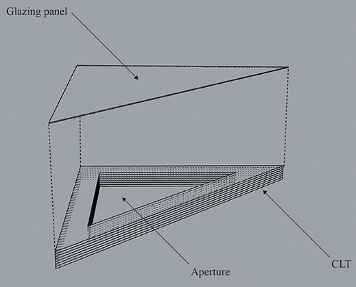
Figure 13. The glazed CLT concept of Panel D.
It might be prudent at this stage to stress that as with all strategies based on multiple-objective analysis, the idea of architectural “performance” is not necessarily limited to such easily quantifiable metrics as illuminance. The present study focuses on this particular parameter as it supports the brief of the prototypical building for which the study is made: a building that needs to be properly illuminated, preferably using natural daylight, for both thermal comfort and energy consciousness reasons.
The conflicting objectives of the morphodynamic systems of the previous experiments (which effectively define the panels capable of carrying fenestration), together with a new morphodynamic system, the parametrically controlled constraint on how large a percentage of those faces that are assigned glazing (again based on an anticipatory simulation of probable future scenarios), combine to make this a teleodynamic fenestration strategy. The transparent (contragrade) apertures “break open” the opaque (orthograde) skin to let light into the building and allow it to reach its daylight performance targets. The final combination of element types is shown as an exploded diagram in (Figure 14). A rendered model of the final teleodynamically designed building envelope is shown in (Figure 15).
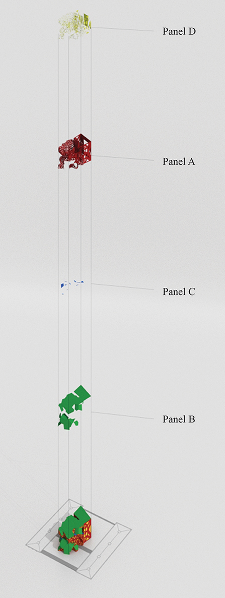
Figure 14. Exploded diagram showing the final combination of element types.
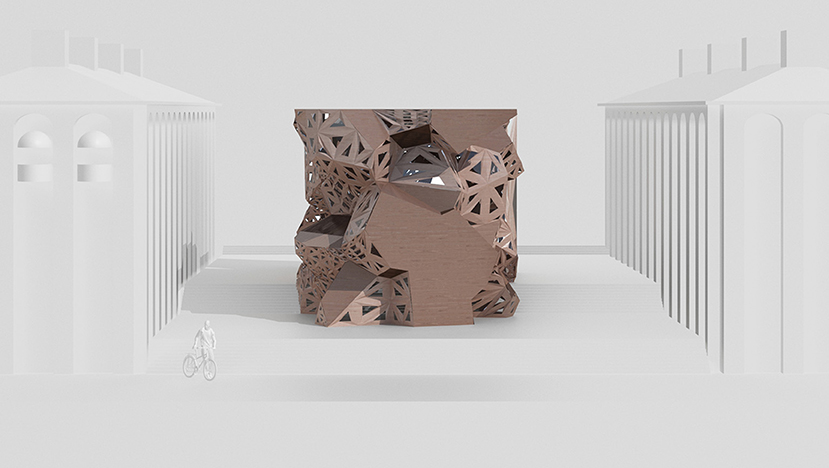
Figure 15. Rendered 3d model of the final teleodynamically designed building envelope.
Discussion
Experiment stages I-IV above optimised a building envelope for durability on the very site where the structure is to be built. Through COW's optimisation procedures, the building envelope is subdivided into a pattern of façade elements, which can be assigned a predefined number of specific properties/durability capabilities. These different elements can be optimally combined for best environmental/durability performance under the site-specific conditions, while simultaneously considering the optimal lighting conditions for the indoor environment. In the experiments above, four different element types were predefined in response to site-specific weather and weathering conditions aiming for a mainly wood-based façade system locally adapted to different levels of current weathering and future risk of degradation. The element types could also be defined with other aspects/performance characteristics considered.
While an even less developed version of the COW system was previously used for and presented in a conference paper (Larsson, 2016), the present iteration is still very much an alpha version in its very infancy: much development remains to be carried out to push it further along its software release life cycle and turn it into a fully functional tool that can be properly used for real-life design processes.
A wide range of potential applications for future versions of the prototypical design system could be listed. In the context of material science as it applies practically to the engineering and architecture of timber structures, the Holy Grail is to facilitate a translation between new knowledge of material behaviour at the micro scale and actual changes to the design of an architectural geometry at the macro scale.
The COW system seems to provide one way of facilitating such a translation process, but much research is needed before a solid understanding of the mechanisms involved can be reached. Consider the question “What geometrical reconfiguration of structure x would be the result of a change in material property y?”. How the smallest of “local” changes to an aspect of a structure's composition might result in much larger changes at its “global” scale is an analysis that could allow for a reverse engineering of the design process, from the application of materials to a specified geometry to the generation and specification of a geometry based on material properties.
Conclusions
As stipulated, this study had two goals. Its principal objective, to produce the first iteration of an anticipatory tool for the generative design of innovative timber structures that can be further developed and investigated through forthcoming research, resulted in the COW system. This system was then used to frame a theoretical discussion on how the traditional view of architecture and engineering as predominantly homeodynamic processes might give way to one that views the design process as a teleodynamic system capable of modifying its dynamics to be more effectively supported by extrinsic conditions.
Attaching mechanisms of simulation and anticipation to the design process can improve its usefulness by adding advantages that come with the use of site- and time-specific data streams. Such streams effectively “suspend” an algorithm-driven design iteration in time and space in order to allow it to be parametrically influenced by past or future events such as unique site and project conditions including future local weather predictions or changes to the scheme's political context, economy, or legal circumstances.
Future Studies
While the above discussion provides an incipient theoretical outline for how to use the teleodynamic paradigm within the fields of architecture and engineering, much work remains to be done within this area. Below is an attempt to list some obvious question marks that need to be straightened out at the present, nascent level.
Initial studies could focus on how to define the “concrete space of possibilities with a definite structure” (DeLanda, 2011), and how this space can be efficiently investigated through multiple-objective optimisation operations within an algorithmic/parametric framework, how the “coupling” of morphodynamic processes within such a system can be devised so as to create teleodynamic design iterations, and how the Pareto front of such iterations can best be analysed and evaluated.
What “ententional” qualities could and should be considered as “drivers” of the optimisation processes? What is the full scope of the possibilities that come with the methodological shift of designing not (only) for existing scenarios but (also) for possibilities not (yet) realised?
As mentioned above, the mechanisms featured within COW could theoretically be connected in any order, but different configuration sequences would most likely result in different end results. How to control this and move away from a preconceived sequential combination of components would be another area worth studying further.
Following such initial studies, the relative weighting of the individual desires and driving forces within the system that produce more or less optimised design iterations would be an important contribution towards a fully functional methodology. How can input values be assigned relative levels of relevance and importance? A user object component could be built to be used whenever the system needs to “punish” solutions that do not fall within the pre-specified Frame group reference values. Methods could be created that allow members of the design team to merge the output of several objectives and punish them collectively (so that for instance the total material CO2 emissions are taken into account rather than peak values for individual materials).
Yet another step could involve an optimisation of the optimisation system itself: user object components can be constructed to simplify the creation of new COW components, and a formal set of rules devised to make sure they act in a similar and predictable fashion, based on a common input/output logic. Steps could also be taken to simplify and make the multiple-objective optimisation processes run faster, as they are notoriously slow operations requiring heavy computer processing.
Author Contributions
ML: Substantial contributions to the conception and design of the work; as well as the acquisition, analysis, or interpretation of data for the work; drafting the work and revising it critically for important intellectual content; giving final approval of the version to be published; and agreeing to be accountable for all aspects of the work in ensuring that questions related to the accuracy or integrity of any part of the work are appropriately investigated and resolved. AF, MW: Substantial contributions to the interpretation of data for the work; critical revision; final approval of the version to be published; and agreement to be accountable for all aspects of the work in ensuring that questions related to the accuracy or integrity of any part of the work are appropriately investigated and resolved.
Conflict of Interest Statement
The authors declare that the research was conducted in the absence of any commercial or financial relationships that could be construed as a potential conflict of interest.
Acknowledgments
The authors express sincere appreciation for the financial support from the Svenska Träskyddsföreningen (The Swedish Wood Preservation Industries Association). This study was carried out as part of EnWoBio: the Engineered Wood and Bio-based materials and products laboratory at KTH Building Materials, financed by the Swedish Research Council Formas (Project 2014-172).
We are indebted to the principle developers of the software applications and plug-ins primarily used to assemble the alpha version of COW: David Rutten, Timothy Logan, Robert Vierlinger, Mostapha Sadeghipour Roudsari, Michelle Pak, Chris Mackey, and Giulio Piacentino, and to helpful members of the grasshopper3d.com website forum: Anders Holden Deleuran, Peter Fotiadis, Tom Jankowski, and Hyungsoo Kim. Thanks to Barthélemy Aupetit and Alex Kaiser for assistance with the production of figures. We are very grateful to the referees who carefully went over the manuscript and offered many valuable suggestions that helped us improve its quality.
Heartfelt gratitude goes to Emmett Larsson Levy (who kept questioning the reasoning at a logical level way beyond his 4 years) and Madelaine Levy (who not only applied her remarkable trademark patience throughout the process, but also gave birth to Astor as this paper was written).
Footnotes
1. ^This press release is available online at: http://www.stevenholl.com/projects/raffles-citychengdu.
References
Aguilar-Moreno, M. (2007). Aztec Architecture (FAMSI, Foundation for the Advancement of Mesoamerican Studies). Available online at: www.famsi.org/research/aguilar/Aztec_Architecture.pdf
Aksamija, A. (2013). Sustainable Facades: Design Methods for High-Performance Building Envelopes. Hoboken, NJ: John Wiley and Sons.
Aksamija, A. (2015). “High-performance building envelopes: design methods for energy-efficient facades,” in Proceedings of the Building Enclosure Science and Technology (BEST) 4 Conference, 12–15 April (Kansas City, MO: National Institute of Buildings Sciences).
Ansari, I. (2013). Architecture, syntax, and the emergence of a new subjectivity: Iman Ansari in conversation with Peter Eisenman. Architectural Review, Special issue on Architecture and Representation, May 2013. 94–99.
Blocken, B., and Carmeliet, J. (2004). A review of wind-driven rain research in building science. J. Wind. Eng. Ind. Aerod. 92, 1079–1130. doi: 10.1016/j.jweia.2004.06.003
Blocken, B., Derome, D., and Carmeliet, J. (2013). Rainwater runoff from building facades: a review. Build. Environ. 60:339e361. doi: 10.1016/j.buildenv.2012.10.008
Davies, I. P. (2011). Moisture Conditions in External Timber Claddings: Field Trials and Their Design Implications. Doctoral thesis, Edinburgh Napier University School of Engineering and the built environment, Edinburgh).
DeLanda, M. (2011). Philosophy and Simulation: The Emergence of Synthetic Reason, London: Bloomsbury.
Derbyshire, H., and Miller, E. R. (1981). The photodegradation of wood during solar radiation. Holz als Roh Werkstoff 39, 341–350.
Derbyshire, H., Miller, E. R., Sell, J., and Turkulin, H. (1995). Assessment of wood photodegradation by microtensile testing. Drvna Ind. 46, 123–132.
Dinwoodie, J. M. (1981). Timber: Its nature and behaviour. London; New York, NY: E & FN Spon (2000). First edition 1981 by Van Nostrand Reinhold Co. Ltd), 206.
Eral, H. B., 't Mannetje, D. J. C. M., and Oh, J. M. (2013). Contact angle hysteresis: a review of fundamentals and applications. Colloid Polym. Sci. 291, 247–260. doi: 10.1007/s00396-012-2796-6
Evins, R. (2013). A review of computational optimisation methods applied to sustainable building design. Renewable Sustain. Energy Rev. 22, 230–245. doi: 10.1016/j.rser.2013.02.004
Glanville, R. (2004). The Purpose of Seconds-Order Cybernetics. Kybernetes 33, 1379–1386. doi: 10.1108/03684920410556016
Gold, C. M. (1989). “Voronoi diagrams and spatial adjacency,” in Proceedings G.I.S. – Challenge for the 1990s (Ottawa, ON: Canada), 1309–1316.
Grünbaum, B., and Shephard, G. C. (1980). Tilings with Congruent Tiles. Bull. Amer. Math. Soc. 3, 951–973.
Hicks, R. M. (1965). The fine structure of the transitional epithelium of rat ureter. J. Cell Biol. 26, 25–48.
Hwang, C.-L., and Masud, A. S. M. (1979). Multiple Objective Decision Making–Methods and Applications: A State-of-the-Art Survey. Berlin; Heidelberg: Springer.
IRENA Secretariat. (2012). Renewable Energy Technologies: Cost Analysis Series, Vol. 1. Bonn: The International Renewable Energy Agency (IRENA), 3.
Johnson, A. (2008). Solving Stonehenge: The New Key to an Ancient Enigma. London: Thames and Hudson.
Knowles, R. L. (2003). “The solar envelope,” in Time-Saver Standards for Urban Design, eds D. Watson, A. Plattus, and R. Shibley (New York, NY: McGraw-Hill), 4.6.1–4.6.18.
Larsson, M. (2016). “Parametrics beyond parametricism,” in Proceedings of the 12th Meeting of the Northern European Network for Wood Science and Engineering (WSE): Wood Science and Engineering–A Key Factor on the Transition to Bioeconomy, eds B. Andersons and A. Kokorevics, (Riga).
Logan, T. (2013). Elk 0.3.1. Grasshopper Plug-in to Generate Maps and Topographical Surfaces. Available online at: www.food4rhino.com/app/elk
Mead, M. (1968). “Cybernetics of cybernetics,” in Purposive Systems. Proceedings of the First Annual Symposium of the American Society for Cybernetics, eds H. von Foerster, L. J. Peterson, and J. K. Russel (New York, NY; Washington, DC: Spartan Books).
Menges, A., Schwinn, T., and Krieg, O. D. (2016). Advancing Wood Architecture: A Computational Approach (London: Routledge).
Nguyen, A., Reitera, S., and Rigob, P. (2014). A review on simulation-based optimization methods applied to building performance analysis. Appl. Energy 113, 1043–1058. doi: 10.1016/j.apenergy.2013.08.061
Oberhofnerová, E., and Panek, M. (2016). Surface wetting of selected wood species by water during initial stages of weathering. Wood Res. 61, 545–552.
Piacentino, G. (2009). Weaverbird. Plug-in for Grasshopper. www.giuliopiacentino.com/weaverbird/ The component help text quoted is from the WB tool menu (Transform > wbFrame).
Pryor, A. (2015). Constrained dynamics both orthograde and contragrade. Religion Brain Behav. 5, 65–71. doi: 10.1080/2153599X.2013.826721
Reichert, S., Menges, A., and Correa, D. (2015). Meteorosensitive architecture: Biomimetic building skins based on materially embedded and hygroscopically enabled responsiveness. Computer-Aided Design 60, 50–69. doi: 10.1016/j.cad.2014.02.010
Reinhart, C. F. (2006). Tutorial on the Use of DayDaysim Simulations for Sustainable Design. Cambridge, MA: Harvard University Graduate School of Design.
Robert McNeel and Associates (2014). Rhinoceros 5 SR9 64-bit, 5.9.40617.14345 (June 2014). Grasshopper 0.9.0075 (April 2014).
Robinson, G., and Baker, M. C. (1975). Wind-Driven Rain and Buildings, Technical Paper No. 445, Division of Building Research, National Research Council, Ottawa, Canada.
Rosenblueth, A., Wiener, N., and Bigelow, J. (1943). Behavior, purpose and teleology. Phil. Sci. 10, 18–24.
Rowell, R. M. (2005). “Chemical modification of wood,” in Handbook of Wood Chemistry and Wood Composites, ed R. M. Rowell (Boca Raton, FL: CRC Press), 397.
Rutten, D. (2007). Grasshopper (Robert McNeel and Associates). Available online at: www.grasshopper3d.com
Sadeghipour Roudsari, M., and Pak, M. (2013a). Ladybug. (Plug-in for environmental analysis using Grasshopper.) Available online at: www.grasshopper3d.com/group/ladybug
Sadeghipour Roudsari, M., and Pak, M. (2013b). Honeybee. (Plug-in for building energy and daylighting simulation, connecting Grasshopper to EnergyPlus, Radiance, DayDaysim and OpenStudio.) Available online at: www.grasshopper3d.com/group/ladybug
Solberg, M. (2014). Terrence Deacon's Incomplete Nature (online review, Somatosphere), 1–5. Available online at: www.somatosphere.net/2014/06/terrence-deacons-incomplete-nature.html
Studio Gang Architects (2017). Solstice on the Park. Available online at: www.studiogang.com/project/solstice-on-the-park/pdf
U. S. Forest Service (1966). “Surface characteristics of wood as they affect durability of finishes,” in U.S. Forest Service research paper FPL 57 (Madison, WI: U. S. Department of Agriculture, March 1966).
Vierlinger, R. (2012). Octopus (A Range of Grasshopper Tools Developed by Robert Vierlinger at the University of Applied Arts. Vienna: Bollinger+Grohmann Engineers.
Voronoi, G. (1907). Nouvelles applications des paramètres continus à la théorie des formes quadratiques. Premier mémoire: sur quelques propriétées des formes quadritiques positives parfaites. J. Reine Angew. Math. 133, 97–178.
Wang, W,., Tian, Z., and Ding, Y. (2013). Investigation on the influencing factors of energy consumption and thermal comfort for a passive solar house with water thermal storage wall. Energy Build. 64, 218–223. doi: 10.1016/j.enbuild.2013.05.007
Weinand, Y. (2016). Advanced Timber Structures: Architectural Design and Digital Dimensioning. Basel: Birkhäuser.
Weisstein, E. W. (2009). Voronoi Diagram. MathWorld – A Wolfram Web Resource. Available online at: www.mathworld.wolfram.com/VoronoiDiagram.html
Keywords: teleodynamic architecture, wooden structures, timber, façade, multiple-objective optimisation, preservation-treated wood, EnWoBio Pavilion
Citation: Larsson M, Wålinder M and Falk A (2018) Teleodynamic Timber Façades. Front. Built Environ. 4:37. doi: 10.3389/fbuil.2018.00037
Received: 04 September 2017; Accepted: 25 June 2018;
Published: 11 September 2018.
Edited by:
Michael Budig, Singapore University of Technology and Design, SingaporeReviewed by:
Gearoid Patrick Lydon, ETH Zürich, SwitzerlandChristiane M. Herr, Xi'an Jiaotong-Liverpool University, China
Copyright © 2018 Larsson, Wålinder and Falk. This is an open-access article distributed under the terms of the Creative Commons Attribution License (CC BY). The use, distribution or reproduction in other forums is permitted, provided the original author(s) and the copyright owner(s) are credited and that the original publication in this journal is cited, in accordance with accepted academic practice. No use, distribution or reproduction is permitted which does not comply with these terms.
*Correspondence: Magnus Larsson, bWFnbnVzLmxhcnNzb25AYnl2Lmt0aC5zZQ==