 Gianni Blasi
 Flavia De Luca
 Maria Antonietta Aiello
- 1Department of Innovation for Engineering, University of Salento, Lecce, Italy
- 2Department of Civil Engineering, University of Bristol, Bristol, United Kingdom
The present study is aimed at developing a hybrid approach to consider the effect of concrete cracking on the hysteretic response of RC frames. The mechanical behavior of the concrete is defined according to the smeared cracking approach, while discrete cracking surfaces are included in the geometrical model. The interface behavior of the discrete cracking surfaces is defined by the combination of contact and cohesive elements. The proposed approach is adopted in ABAQUS to simulate an experimental test on a double cantilever column for the calibration of the numerical model. Therefore, a test conducted on a RC portal and modeled numerically for the first time is simulated. Numerical and experimental results are compared in terms of hysteretic force-displacement behavior and cumulative dissipated energy, in order to assess the reliability of the proposed model in simulating the energy dissipation capacity of RC members subjected to lateral cyclic loading. The hybrid modeling approach proposed allows an accurate description of the stress distribution and a fairly satisfactory matching of the hysteretic behavior with a reasonable compromise in terms of computational effort.
Introduction
Finite element (FE) analysis is widely adopted in earthquake engineering, particularly when dealing with systems with a high number of degrees of freedom (DOF), representing the structural configuration of buildings. On the other hand the simulation of the seismic response of RC structures through finite element analysis can be complex and challenging. This is mainly caused by the difference between the mechanical response of concrete and steel rebars and by their consequent complex interaction. In numerical studies, either micro- or macro-modeling approaches are usually adopted depending on the aim of the study, which can require the accurate simulation of several phenomena influencing the response of the frames. Macro-models generally adopt simplified formulation which implicitly consider the influence of the micro-mechanical interaction phenomena on the response of the elements/materials. This approach leads to a significant simplification of the numerical problem. In micro-modeling approaches, the micro-mechanical interaction phenomena are explicitly modeled numerically (e.g., Karavelić et al., 2017; Sinaie et al., 2018) and generally high computational efforts are required. Therefore, when the target of the analysis is global behavior of RC structures, generally macro-models are preferred (e.g., Vamvatsikos and Fragiadakis, 2010; De Risi et al., 2017). This is mainly due to the substantial reduction of the computational effort required with respect to micro- and meso-models. In the last decades, large numbers of macro-models have been developed, able to accurately reproduce the response of RC members. On the other hand, for the accurate reproduction of stress/strain distribution in the elements subjected to cyclic loads, micro- and meso-models still represent the best option. The latter approach represents the compromise between micro- and macro-modeling, featuring a simplification of the numerical problem aimed at accurately evaluate only the phenomena which are object of the analysis. For this reason, the difference between macro- and meso-models can't be unambiguously defined. In macro-models, RC frames are usually modeled through beam elements, while both micro- and meso-models generally feature solid or shell elements to represent the concrete region, whereas the steel reinforcement is simulated with embedded beam/truss elements (e.g., Viswanathan et al., 2014; Redmond et al., 2018).
Mechanical models for concrete and steel, available in most of the FE platforms, allow reproducing the stress-strain response under monotonic loading and the degradation of the strength and stiffness due to cyclic loading. The mechanical response of the steel is generally reproduced adopting a symmetric bi-linear behavior, characterized by kinematic or isotropic hardening laws; even if in some cases the compressive response is modified to take into account the buckling phenomenon on rebars.
Although the simulation of the concrete response is more challenging; as well-known, the compressive behavior is characterized by a post peak softening slope, influenced by different parameters, such as the confinement (Mander et al., 1988), while the tensile response is generally composed of an elastic branch up to the tensile strength of the concrete, followed by concrete cracking.
The post-cracking response of concrete can be simulated adopting the smeared cracking approach (Lotfi and Shing, 1991; Lee and Fenves, 1998), where cracks are not explicitly defined in the geometry of the model but they are implicitly considered in the mechanical response of the material.
The smeared cracking approach has been widely adopted in numerical studies to reproduce the monotonic response of RC frames (Sinaei et al., 2012; Sümer and Aktaş, 2015; Ors et al., 2016); although this mechanical model is not always able to accurately reproduce the response of concrete under cyclic loading.
The discrete cracking approach is an alternative method to reproduce the crack opening in the concrete (Dolbow et al., 2001; Giner et al., 2009), it generally allows high simplifications of the mechanical model adopted for the concrete. Discrete cracks develop in the mesh once the tensile strength or the cracking energy is attained and they can be explicitly identified in the post processing.
The two methods discussed allow the accurate reproduction of the effects of crack development in concrete members, but, in many cases, they are time consuming and lead to convergence issues.
Furthermore, when dealing with the cyclic behavior of the concrete members, the effects of the cyclic opening and closure of the cracks should be considered in the numerical simulation; in the smeared cracking approaches, this leads to a significant increase of the complexity of the mechanical model (Koutromanos and Shing, 2012; Redmond et al., 2018), while the eXtended Finite Element Method (XFEM) requires the definition of a contact law along the cracking surfaces, which is not pre-defined in the geometrical model (Yu et al., 2016).
The present study is aimed at proposing a hybrid approach using ABAQUS (Dassault Systemes, 2016) which combines the discrete cracking approach and the smeared cracking approach. The cracking surfaces are pre-defined in the numerical model by splitting the geometry in different “macro blocks”; along the cracking surfaces, cohesive and contact laws are defined, in order to simulate the crack opening and closure, respectively.
This approach makes possible to simplify the definition of the mechanical response of the concrete, since the cyclic opening/closure is not implicitly taken into account in the tensile behavior definition. Furthermore, since the cracking paths are predefined in the geometry, the contact and cohesive laws are only defined for specific surfaces in the geometry, leading to a significant reduction of the computational efforts.
The proposed approach is aimed at reproducing the hysteretic response of RC members subjected to cyclic lateral loading. In order to assess the reliability of the proposed model, a test on a double cantilever column was simulated (Ohue et al., 1985) by proposing different modeling approaches. The monotonic and hysteretic response of the numerical simulations were compared to the experimental results with a particular focus on the influence of the adopted model on the accuracy of the reproduction of the shape of the hysteresis loops. Then, a recent experimental test on a RC portal conducted by Verderame et al. (2016) is modeled numerically for the first time in order to assess preliminarily the reliability of the proposed approach. Hysteretic force-displacement response is evaluated and the numerical and experimental results are compared, in order to assess the accuracy of the simulation of the cyclic loops.
Micro-Modeling of RC Frames—Issues in the Simulation of the Cyclic Behavior
Most of the mechanical models available on FE platforms to simulate the behavior of the concrete take into account the significant asymmetry of the response in compressive and tensile direction. The compressive stress-strain relationship of the concrete is represented through a non-linear formulation (Figure 1A) whose parameters depend on the reinforcement details, as the post-peak softening response, being highly influenced by the transverse reinforcement (Mander et al., 1988). On the other hand, the tensile behavior definition depends on the approach adopted to simulate the concrete cracking.
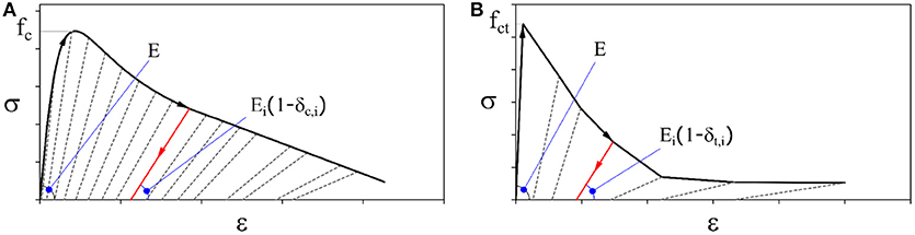
Figure 1. Example of mechanical model for concrete in compression (A) and tension stiffening (B).
The response of RC members under cyclic lateral loading is indeed highly influenced by the cracking of concrete, which modifies the energy dissipation capacity. The pinching effect characterizing the flexural response of frames is caused by the cyclic closure/opening of cracks, leading to a significant reduction of the stiffness in the load-inversion phase, due to the closure of the cracks. Depending on the adopted approach, the cyclic loops characterizing the lateral response of a RC frame can be reproduced in different ways, explained in the following section.
The Smeared Cracking Approach
In the smeared cracking approach, the development of cracks in the concrete is considered by defining a post-peak tensile response of the material. Thus, rather than tracking individual “macro” cracks in the geometrical model, the presence of cracks is considered implicitly by modifying the stress and the material stiffness associated with the integration point. After the attainment of the tensile strength of the concrete (fct), a post-peak softening branch (tension stiffening) simulates the progressive degradation due to the crack openings. Tension stiffening is reported in Figure 1B and can follow either linear or exponential laws.
In this approach, the simulation of the crack closure, requires an increase of the complexity of the material model (Koutromanos and Shing, 2012) and, as said before, highly influences the dissipation capacity of the frame members.
As reported in Figure 1B, once unloading takes place, after the crack has opened, the unloading branch stiffness is equal to the elastic stiffness, reduced by a factor δt that takes into account the degradation due to damage. As soon as the elastic displacement is restored, the crack closure stage begins and a significant reduction of the stiffness up to the complete closure of the crack is observed. At this point, the elastic stiffness is restored and compression takes place; the variation of the stiffness during the load inversion phase (pinching) is more marked in case of relevant crack patterns in RC members.
The analytical formulation to simulate the monotonic response of concrete usually requires the definition of two yielding surfaces; the first one is referred to the end of the elastic branch in compression, at which the linear stress-strain law turns into an exponential one. The second yielding surface is referred to the end of the elastic slope in tension, where tension stiffening takes place.
The model proposed by Oliveira and Lourenço (2004) was adopted in finite-element analysis of masonry structures to simulate the cyclic behavior of interface elements; although the same formulation can be used for concrete. The cyclic response is defined by the adoption of two auxiliary yielding surfaces moving within the monotonic yielding surface, representing the unloading/reloading phase.
The monotonic surfaces are active when either only monotonic loading has occurred or the stress point reaches the monotonic yielding surfaces during an unloading process. The proposed model was validated by comparisons with experimental results of uniaxial tests on concrete and was assessed to be highly reliable to simulate all the phenomena characterizing the cyclic response of asymmetric materials as concrete.
In some cases, mechanical models available in finite-element software packages are unable to simulate the response under cyclic loads, particularly in case of large tensile strain/displacement (Figure 2A); compression stiffness recovery in the reloading phase can occur earlier than expected, depending on the criterion adopted in the model to discern the transition from tension. As observed by Nikaido et al. (2015), if the compression stiffness recovery is detected at zero stress point, the pinching effect simulation can be challenging, since the crack closure cannot be accurately reproduced in the numerical model (as shown in Figure 2B).
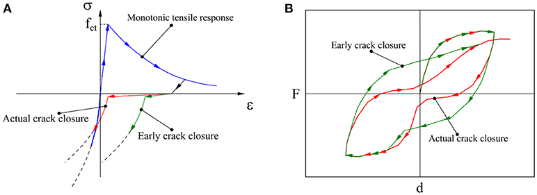
Figure 2. Effect of the cracking closure simulation (A) in the mechanical model and (B) in the global response showing the pinching effect.
In other cases, the auxiliary yielding surfaces are not even defined and the stiffness degradation, representing the cracking closure, does not take place.
If the mechanical model is unable to produce a satisfactory simulation of the pinching effect, a significant mismatch is obtained in the numerical simulation of the flexural response of RC members in terms of energy dissipation, since cracking of the concrete leads to a noticeable decrease of the energy dissipated.
The Discrete Cracking Approach
In the discrete cracking approach, the cracking process is ruled by cracks developed in the geometrical model; the most used modeling approaches are the extended finite element method and the adoption of cohesive elements to express the post-cracking response of the concrete.
The XFEM was developed by Moës and Belytschko (2002); it allows to significantly simplify the definition of the tensile response in the mechanical model of the material. The cracking path is generated by adding discontinuous basis functions to standard basis functions for nodes where cracking energy/displacement is computed, in order account for the displacements due to crack opening. The main advantage in the XFEM is that no update of the mesh is required to track the crack path, thus, the mesh-dependency of the results is significantly reduced with respect to a smeared cracking approach.
Since the XFEM allows to model the discontinuity in a displacement field along the crack path, the simulation of the crack growth requires an accurate definition of the fracture modes; generally, the cracking path is computed adopting the mixed mode in order to consider not only the response under uniaxial traction (Ballatore et al., 1990). Dolbow et al. (2001) also incorporated friction laws in order to simulate more accurately the crack growth under compression, which is an important feature when dealing with cyclic response of the frame members.
Since the crack path is not pre-defined, the accurate simulation of the cyclic response of reinforced concrete members requires the inclusion of contact laws in order to consider the effect of the crack closure. This assumption generally leads to high computational effort, and in many cases can cause convergence issues, particularly when dealing with RC members with embedded rebars, for which multiple crack paths are expected to develop under cyclic lateral loading.
Discrete cracking approaches adopting cohesive elements rather than XFEM have been also widely adopted in the literature (Bocca et al., 1991). The so-called discrete interelement cracks require remeshing in the model after the generation of the cracks, since the path is defined between the elements. This method is similar to the XFEM since the crack path is not pre-defined and can lead to high computational efforts as well as convergence issues. Notwithstanding the discussed issues, it was used specifically to simulate the lateral response of reinforced concrete members as well as crack growth in ductile materials (Tvergaard and Hutchinson, 1996; Gullerud et al., 2000).
The so-called intraelement approach features the incorporation of embedded discontinuities in the geometry (Belytschko et al., 1988), to simulate the post cracking response of the material. This approach allows the pre-definition of the crack paths, identified by a preliminary analysis of the stress distribution along the member, in order to define the regions where cracks are most likely to develop. Despite this approach reduces the complexity of the model, in some cases the preliminary definition of the crack paths may be difficult, as in the case of RC members subjected to cyclic loading.
In the study proposed by Yu et al. (2016), the simulation of the pinching effect characterizing the flexural cyclic response of a RC column, was conducted providing a novel modeling approach, developed through combination of the XFEM, to detect the crack paths in concrete, traction-separation cohesive laws to simulate the post-cracking response, and contact elements to take into account the clack closure process. A satisfactory simulation of the experimental response of RC frame members was obtained and the comparison between experimental and numerical hysteretic loops demonstrated the high reliability of the model in simulating the pinching effect.
An alternative discrete cracking approach for the simulation of the lateral response of RC members was proposed by Stavridis and Shing (2010). Triangular elements were connected with double-node interface elements, simulating the post cracking behavior of the concrete. The model was validated by comparing numerical results with experimental tests on infilled frames, showing a good match with the experimental backbone curve (Stavridis and Shing, 2010; Redmond et al., 2018).
A similar approach was recently developed from Zivaljic et al., 2013, combining triangular plane-stress elements with discrete cracking interfaces to reproduce concrete cracking and embedded one-dimensional elements simulating steel rebars. The bar slip was also considered by defining a pre- and post-cracking mechanical model for steel. The proposed model was adopted for the simulation of several reinforced concrete elements and was assessed to be very reliable in reproducing the crack paths in concrete (Zivaljic et al., 2013; Živaljić and Nikolić, 2014; Nikolić et al., 2017).
Also in this cases, a satisfactory simulation of the pinching required a complex mechanical model for interfaces elements, increasing the computational efforts.
The Simulation of the Hysteretic Response in the Proposed Approach
As discussed in section Micro-Modeling of RC Frames—Issues in the Simulation of the Cyclic Behavior, the main issues in the simulation of the cyclic response of RC members under lateral loading are related to the pinching effect; when the post cracking behavior is defined in the mechanical model of the material, the process of crack closure requires a significant increase of the complexity of the formulation, while in discrete cracking approaches, the cracking closure must be simulated by the inclusion of contact laws, which can lead to convergence issues. XFEM method was assessed to be reliable when simulating the lateral response of RC members under monotonic lateral loads even if the post-cracking behavior of the concrete is not defined in the material model (Zi and Belytschko, 2003). On the other hand, the adoption of this method requires an oversimplification of the response of the material in compression, which in many cases was assumed to be linear elastic (Dolbow et al., 2001; Liao and Huang, 2015). When analyzing the non-linear response of frame members experiencing displacements far beyond the yielding point, the simplified assumption on the compressional behavior of the material becomes questionable and the post-peak actual response of the element can be mismatched.
Description of the Numerical Model
In the numerical model developed using ABAQUS, an equivalent bi-dimensional system is proposed to simulate the cyclic lateral behavior of a RC portal. 4-node bilinear shell elements with reduced integration (CPE4R) are adopted for concrete, while both longitudinal and transverse rebars are modeled using linear truss elements (T2D2), embedded in the concrete geometry (Figure 3A).
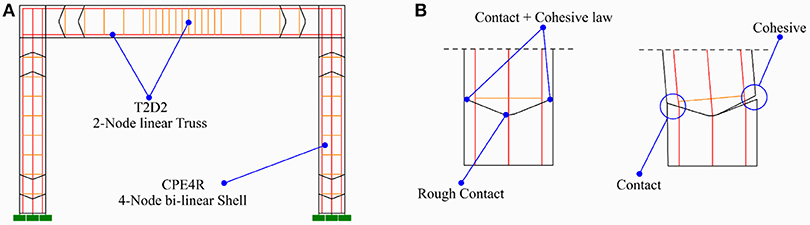
Figure 3. (A) Numerical model and (B) interface interaction.
The mechanical behavior of the concrete is defined adopting a Concrete smeared cracking model available in the software. As evidenced by Nikaido et al. (2015), the latter is unable to accurately simulate the crack closure process, since earlier compressive stiffness restore occurs in the unloading phase when the tensile deformation is relevant. Thus, a combination of the smeared and discrete cracking approach is adopted to simulate the pinching effect.
A bilinear kinematic hardening relationship was adopted for the definition of the mechanical behavior of the steel rebars, assuming a symmetric response in tension and compression.
In order to accurately define the compressive response of the concrete, the well-consolidated and widely adopted formulation proposed by Mander et al. (1988) was considered; which takes into account the transversal reinforcement ratio to define the ductility and strength capacity of the material. The tensile response was assumed to be elastic-perfectly-plastic with no tension stiffening, since the crack opening was modeled following a discrete approach by the adoption of cohesive laws. The model was implemented by direct input of the stress-strain backbone curve in the mechanical model available in the software (Concrete damaged plasticity); the parameters required for the definition of the plastic flow and the yield function are assumed considering values suggested from the literature (Lubliner et al., 1989; Lee and Fenves, 1998).
The Interface Interaction
According to different experimental and numerical studies (Sneed et al., 2016; Duan et al., 2017), flexural cracks are most likely to develop along the discontinuity surfaces, represented by the transversal rebars running through the concrete. Thus, in the proposed model, discrete crack paths are preliminarily defined in the geometry.
The path initiation position corresponds to the stirrups in the frame (Figure 3B), while the inclination is defined according to the variable strut inclination truss model (EN 1992-1-1, 2004; Fardis, 2009), assuming an angle of inclination of the compression stress field equal to 21.8°. Moreover, in order reduce the computational efforts, the paths are only included in the zones with the highest value of flexural moment. The geometry of concrete members is divided in different “macro-blocks,” whose interaction is defined through cohesive and contact relationships.
The interface zone between the macro blocks is divided in three parts, as shown in Figure 3B; the external parts represent the crack paths, while the central part is a rough connection assumed as the center of the rotation of each block. The assumption of a central rough connection means that cracks in the members can only evolve up to the external boundaries of the central zone; as consequence, the latter must be adequately restricted, in order to assume that the collapse of the member is attained before cracks develop up to the central zone.
Depending on the direction of the load, the two external zones are characterized by compression and tension stress regime, respectively (Figure 3B); thus, either cohesive or contact laws are activated along the surfaces, on the basis of the stress regime.
The contact law is defined in order to simulate the complete closure of the crack, when the elastic compression stiffness is restored. The augmented Lagrange method (Powell, 1969) is adopted to compute the contact stress, while the contact stiffness is automatically defined depending on the stiffness of the elements experiencing the contact. This approach also allows to take into account the compressive stiffness reduction due to cyclic loading, by including compressive degradation in the mechanical model of the concrete.
The stiffness factor for the contact surfaces is assumed to be unitary, both for external and central surfaces.
In the initial stage, no gap exists between the blocks, and all the contact surfaces are in a closed status; since for the external zones separation of the surfaces is expected, the contact detention is ruled by the definition of a minimum gap between the nodes, this assumption assures contact elements being active every time that surfaces cyclically experience contact.
Once traction takes places along the surface, the separation between the surfaces follows a stress-displacement law, obtained as a function of the post-cracking stress-strain relationship of concrete, reported in Figure 2A.
The first elastic branch is defined considering the stiffness of the shell elements, thus, it takes into account the stiffness degradation by including a degrading tensile law in the mechanical model of the concrete.
The stress limit at the end of the elastic branch is equal to the tensile strength of the concrete. The post-peak behavior is ruled by an exponential law, according to analytical models expressing the tensile response of concrete available in the literature (Pramono and Willam, 1989; Mehta and Monteiro, 2006). In this study, an exponent equal to three is assumed to define the softening branch after the attainment of the tensile stress. Once the displacement between the surfaces reaches the residual limit, the cohesive law is inactive, meaning that no stress-displacement relationship exists between the surfaces. At this stage, once the load is reversed, the closure of the crack is represented by a displacement with zero-stress variation along the elements, making possible to simulate the pinching effect in the global response of the frame. As said before, once the crack is completely closed, the elastic compressive stiffness is partially restored, according to the compressive degradation law defined in the mechanical model of the material.
By this procedure, the pinching effect is “lumped” in the cracking interfaces; beside this, the effect of the cracking of the concrete on the flexural response in terms of strength is still considered in the whole model, by the definition of a tensile strength limit for the concrete, as well as tension stiffening.
Numerical Simulation of Quasi-static Cyclic Test on RC Portal
The numerical model developed was firstly validated considering the experimental test conducted on a double-cantilever column by Ohue et al. (1985). The column tested (named non-ductile column or NDC), reported in Figure 4 featured a cross section equal to 200 × 200 mm and a height equal to 800 mm. The longitudinal reinforcement was composed of 2 + 2 rebars with 16 mm diameter, while transverse reinforcement was realized adopting 5.5 mm stirrups with spacing equal to 50 mm.
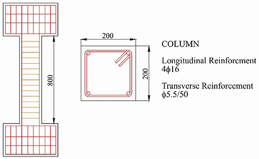
Figure 4. Description of the NDC specimen tested by Ohue et al. (1985).
Axial load was applied on the top of the column to simulate the presence of the gravity loads. The cyclic lateral load was applied in displacement-control and it was composed of 9 load steps, each of them characterized by two fully reversed cycles at the same displacement amplitude.
A mixed shear-flexural failure mode of the specimen was observed in the test, featuring major shear cracks at a displacement amplitude equal to 17.5 mm (drift equal to 2.2%).
In order to assess the reliability of the proposed model in predicting the lateral behavior of RC portals, a campaign available in literature and never modeled numerically, was considered to carry out a numerical simulation. The reinforced concrete frame (named ductile frame or DF) tested by Verderame et al. (2016) was designed according to provisions of the Italian seismic code NTC08 (2008), in order to simulate the behavior of seismic designed frames.
In DF (Figure 5), the longitudinal reinforcement of the beam is symmetric and made of three top and three bottom 10 mm bars. 12 mm bars were used for the column reinforcement, in order to follow the capacity design approach. Transverse reinforcement of the beam and the columns was composed of 6 mm stirrups, whose spacing was equal to 100 mm in all the three elements and 50 mm in the “critical zones,” i.e., the end regions of columns and beams and in the mid span of the beam.
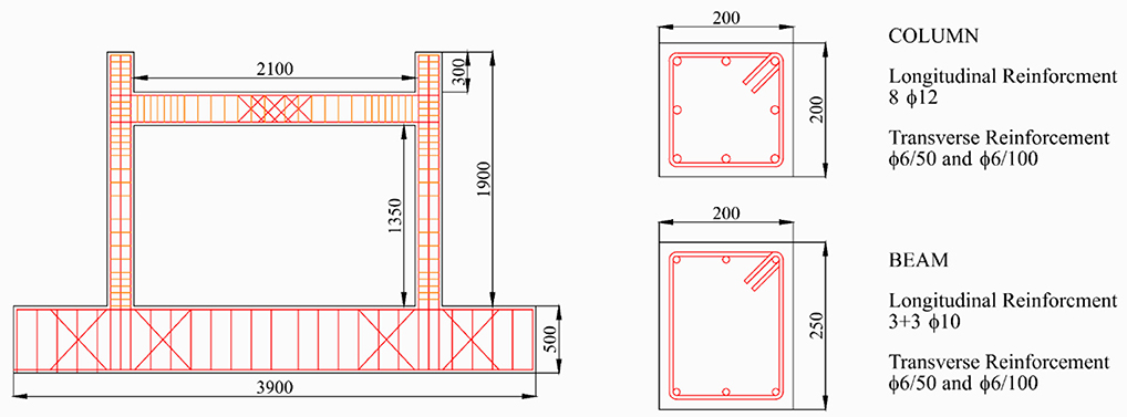
Figure 5. Description of the DF specimen tested by Verderame et al. (2016).
The experimental test was carried out by the application of cyclic lateral load at the mid-span of the beam; the loading protocol was composed of fully reversed displacement-controlled load cycles, whose displacement amplitude was increased at each load step up to the failure of the specimen. For each load step, three fully reversed cycles were executed.
The axial load was applied on top of the column during the quasi-static cyclic tests, to simulate gravity loads due to the presence of higher floors in a five-story building.
In the test, the first damage was characterized by flexural cracking at the beam ends. By increasing the displacement amplitude, flexural cracks developed in the column ends, too. The peak lateral strength was attained after the widening of the flexural cracks in beam ends and in the bottom of the columns. As expected for seismic designed frames, the collapse mechanism was caused by major cracking in beams, according to a strong column/weak beam mechanism behavior. The failure of the specimen was attained at a drift Δf equal to 5.3% (see Verderame et al., 2016 for further details).
Numerical Simulation of the Tests in ABAQUS
In the numerical simulation in ABAQUS, different configurations of the finite element model are analyzed, in order to evaluate the influence of the proposed modeling approach on the numerical results. A Finite-Element “standard” (FES) model is firstly developed, with the aim of assessing the accuracy of the material model available in ABAQUS in simulating the pinching effect. The only difference between FES model (reported in Figure 6A) and the Finite-Element model with macro Blocks (FEB) model proposed in section Description of the Numerical Model is the absence of the macro blocks in the geometry, meaning that a fully smeared cracking approach is adopted, without the definition of contact and cohesive laws to simulate the cyclic opening and closure of cracks, leading to a high simplification of the numerical problem.

Figure 6. Illustration of (A) FES model, (B) FEB1 model, and (C) FEB2 model.
In FES model, the size of shell elements is assumed equal to 50 mm in the whole geometry, while, in FEB model, it is gradually reduced from 50 to 10 mm in proximity to the interfaces between the macro blocks. Referring to the truss elements adopted to simulate longitudinal rebars, a length equal to the stirrups spacing is assumed.
Furthermore, referring to FEB model, two different configurations were developed (Figures 6B,C) for the test considered; in order to analyse the influence of the simulation of bond between concrete and steel rebars on the accuracy of the simulation of the hysteretic loops characterizing the lateral response of the portal.
In the first configuration (FEB1), the end zones of beams and columns are divided in two macro blocks, meaning that two discrete cracking surfaces are included. Bar slip is not considered and the truss elements are embedded in the concrete region. In the second configuration (FEB2), which features the same number of blocks adopted for FEB1, bar slip is modeled through linear elastic connectors between trusses representing longitudinal rebars and shell elements. The mechanical behavior of the connectors is defined according to CEB-FIP (2010).
It is worth mentioning that the same approach was adopted for each of the experimental tests simulated, even if Figure 6 is referred to the model adopted for the portal tested by Verderame et al. (2016). The double-cantilever model for the simulation of the test by Ohue et al. (1985) featured an encastre restraint for both the bottom and the top nodes of the column.
A dynamic analysis adopting implicit method was carried out; monotonic and cyclic displacements were applied on top of the frame and the column as boundary condition to reproduce the loading protocol applied in the experimental tests, while the base shear at the fixed supports was computed during post-processing in order to plot monotonic and cyclic load-displacement relationships.
Comparison Between Numerical and Experimental Results
The numerical simulation of the test on the NDC confirms the low reliability of the mechanical model of the concrete available in the software in simulating the cyclic response of reinforced concrete columns. Firstly a monotonic push-over analysis was carried out, in order to obtain the monotonic response of each model developed (Figure 7). No significant variation in observed in terms of yielding strength and pre-yielding stiffness for FES and FEB1, confirming the equivalence of the two models in the simulation of monotonic behavior.
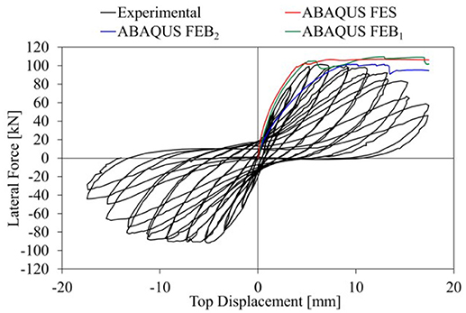
Figure 7. Comparison between the monotonic response of the three FE model developed and the cyclic experimental response of NDC.
On the other hand, FEB2 model featured a lower stiffness due to the bar slip. The variation of the yielding strength with respect to the experimental test is equal to +1.5, +.2%, and +1.1% for FES, FEB1, and FEB2, respectively. The elastic stiffness increased by 13% for both FES and FEB1 while a decrease of 36% was observed for FEB2. The FES and FEB1 featured a hardening response leading to an increase of the ultimate strength with respect of the experimental results. This feature suggests that the strength degradation obtained in the experimental test could be an effect of the cyclic loading, therefore it couldn't be reproduced through a push-over analysis. On the other hand, the strength degradation obtained in FEB2 simulation, was caused by the bar slip, leading to a softening behavior and a higher accuracy of the simulation in terms of strength.
The comparison between the hysteretic response of FES and FEB1 and the experimental test is reported in Figure 8. The introduction of the macro-block in the model leads to a significant reduction of the energy dissipation and the elastic stiffness of the backbone curve with respect to the FES model. Furthermore, the pinching effect observed in the experimental response is only simulated in FEB1, confirming the limit of the original model for the concrete in accurately simulate the cracking closure process. Lastly, the isotropic hardening of the reinforcement steel observed in FES simulation led to a significant increase of the maximum strength with respect to the experimental test as well as to the corresponding maximum strength obtained from the push-over analysis. Referring to FES, the maximum strength obtained increased by 14% with respect to the experimental result (+7% with respect to the monotonic response), Also in FEB1 model the isotropic hardening affected the global response in the first cycles, as evidenced by the different shape of the hysteretic loops comparing numerical and experimental response for low displacement amplitude. The increase in maximum strength observed for FEB1 was 11% comparing to experimental test (+3% with respect to the monotonic response). Despite being affected by the isotropic hardening model of the reinforcement steel, the cyclic response of FEB1 featured pinching effect and a satisfactory simulation of the experimental response was obtained comparing to experimental curve.
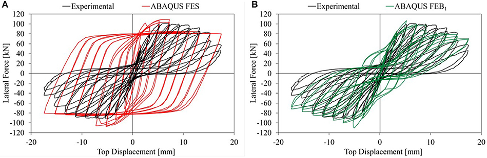
Figure 8. Numerical simulation of NDC adopting (A) FES model and (B) FEB1 model.
The introduction of the bond between steel rebars and concrete led to a significant increase of the accuracy of the experimental response simulation (Figure 9). The pinching effect simulation caused by the bar slip significantly affected the shape of hysteretic loops and led to a reliable simulation of the total energy dissipated (−19% with respect to the experimental test).
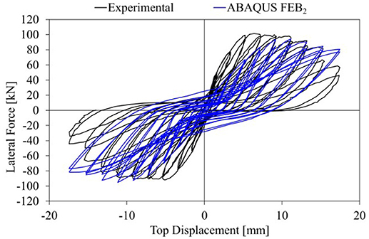
Figure 9. Numerical simulation of NDC adopting FEB2 model.
A good correspondence in terms of maximum strength was also observed, with a difference of 4.1% between numerical and experimental results. On the other hand, the inclusion of the bond in the numerical model affected the elastic stiffness, which was 45% lower in the numerical simulation.
The total energy dissipated, ED is reported in Table 1. In the FES a significantly higher value is obtained with respect to the ED of the experimental test (+252%), due to the absence of pinching and the isotropic hardening effect obtained in the model. For FEB1 and FEB2, a higher accuracy in the simulation of the crack opening/closure due to the presence of the macro-blocks led to a satisfactory matching of the experimental curve and, consequently, the ED. Furthermore, the bar slip simulation characterizing the FEB2 approach reduced the influence of the cyclic response of the reinforcement steel on the global behavior of the column.
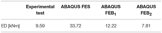
Table 1. Total energy dissipated for experimental test and numerical models referring to NDC.
The numerical simulation of the test on the DF specimen shows a significant variation of the results depending on the modeling approach adopted. The hysteretic force-displacement (F-d) behavior obtained considering the FES model (Figure 10A) confirms the assessments made in previous sections. No pinching effect is observed in the cyclic response of the frame, leading to a significant increase of the energy dissipated in the numerical model with respect to the experimental test. Furthermore, isotropic hardening effect is observed in hysteretic loops obtained from the numerical simulation, caused by the influence of the cyclic behavior of steel rebars on the lateral response of the frame.
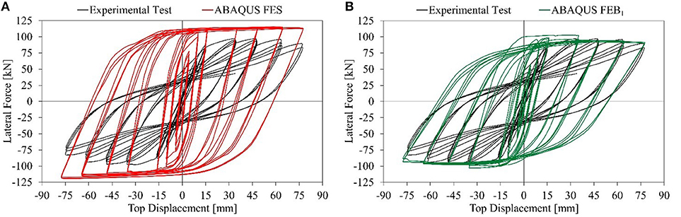
Figure 10. Numerical simulation of DF adopting (A) FES model and (B) FEB1 model.
In FEB1 (Figure 10B), the bar slip is not simulated since embedded constraints were adopted between the nodes of shell and truss elements. For this reason, an increase of the maximum lateral stiffness is obtained in the numerical model compared to the experimental test. The absence of bar slip increases the influence of the rebar deformation on the strain developed in the shell elements, and the crack opening is not adequately simulated. On the other hand, higher quality of the matching of the experimental test can be observed in terms of strength and stiffness, even if the pinching effect is not simulated.
Comparing FES results to experimental ones, an increase of 199 and 24% is obtained in terms of elastic stiffness, Ek, and yielding strength, Fy, respectively. Considering FEB1, the Fy is 11% higher than the value obtained from the test, while Ek increases by 111%.
For FEB2 model (Figure 11), a better matching of the experimental results is obtained both in terms of strength and stiffness. The simulation of the bond leads to a significant reduction of the elastic stiffness with respect to FEB1 (−64%), while bar slip was found to have a sensible influence on the pinching effect.
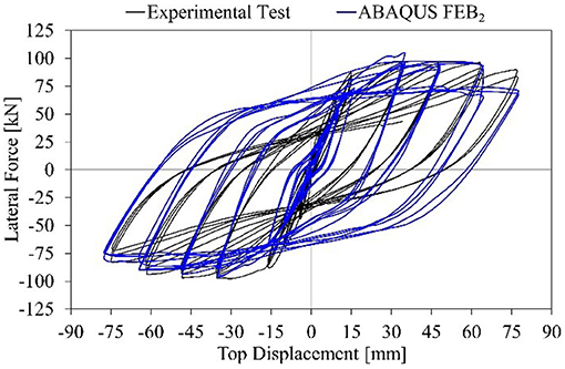
Figure 11. Numerical simulation of DF adopting FEB2 model.
Comparing experimental to numerical results, an increase of 10% is obtained for Fy considering FEB2, while the elastic stiffness decreases by 23%. It is worth saying that FEB2 simulation is the only one which features a decrease of the elastic stiffness with respect to the experimental test.
Lastly, the energy dissipation capacity is also computed for the analyzed frame. The cumulative dissipated energy (CDE), evaluated as the sum of the areas of the hysteretic loops in the F-d response, is reported in Figure 12. Considering FES and FEB1, a significant increase of energy dissipated is observed even for low displacement amplitude, while in case of FEB2, a very satisfactory match is obtained in the early stage.
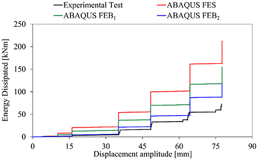
Figure 12. Cumulative dissipated energy obtained for experimental test and numerical models.
This assessment is confirmed by the comparison of the hysteretic loops of Figures 10, 11.
The pinching effect is more noticeable in the first loops in case of FEB2, while the more the displacement amplitude increases, the more the difference between the experimental and the numerical CDE increases.
This effect could be caused by the increase of the strain in shell elements adjacent to the cracking surface for high displacement amplitudes.
For high displacements, the interaction between the stress components in shell elements adjacent to the crack leads to a significant increase of the strain, causing a distortion of the geometry in the crack closure phase. For this reason, the cyclic loops obtained for high displacement amplitude are significantly influenced by the hysteretic behavior of the steel, which is not characterized by pinching.
The total energy dissipated, ED, is reported in Table 2. As expected, ED in the FES and FEB1 models is significantly higher with respect to the ED of the experimental test, due to the absence of pinching and because of the higher stiffness obtained in these simulations. For FEB2, a better simulation is obtained, confirming the need of accounting for the bar slip in the simulation of the hysteretic response when dealing with reinforced concrete members.
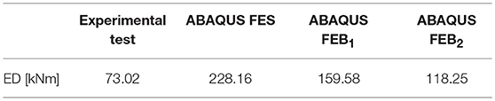
Table 2. Total energy dissipated for experimental test and numerical models referring to DF.
The efficacy of the proposed model was also assessed by comparing CPU time of the numerical analysis (Figure 13). Since the time is significantly influenced by the processor clock rate, the comparison is provided in terms normalized CPU time (CPUn) referring to the FES model, which is the simplest configuration developed.
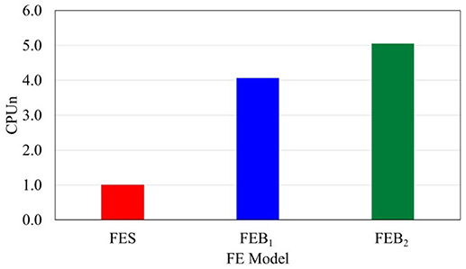
Figure 13. CPU time comparison between FES, FEB1, and FEB2.
As expected, the absence of the discrete cracks in the FES model led to a significant reduction of the CPU time with respect of both FEB1 and FEB2. The presence of the macro blocks and, consequently, the inclusion of contact and cohesive laws increased by 307% the solver time, while by including the bond between concrete and steel rebars the increase was 405%.
Even if more complex and more computationally demanding, the FEB2 model is still an appealing and simply-to-model alternative for FE analyses with reduced effort with respect to more complex approaches (e.g., Stavridis and Shing, 2010; Yu et al., 2016).
Conclusions
Different numerical studies focussed on the seismic response of reinforced concrete members pointed out the issues when attempting to accurately reproduce the effects of the cyclic opening and closure of the cracks in concrete when adopting meso- and micro-modeling approaches. In different finite element platforms, mechanical models simulating the concrete tensile response as well as extended finite element methods available allow to accurately reproduce the crack opening process but lead to a significant increase of the computational efforts as well as convergence issues when simulating the effects of the crack opening on the cyclic response of the frames. Furthermore, in some cases the results obtained adopting a smeared cracking approaches show a significant difference compared to the actual behavior observed in experimental tests.
The hybrid modeling approach proposed in the present study was assessed to significantly improve the accuracy of the simulation of the hysteretic loops characterizing the lateral behavior of reinforced concrete members. The smeared cracking approach adopted to define the mechanical response of the concrete was combined with a discrete cracking approach through the introduction of pre-defined cracking path in the regions subjected to higher values of tensile stress.
Contact and cohesive interaction laws were adopted to define the mechanical response along the cracking paths in order to simulate the cyclic crack opening and closure. Two different configurations of the proposed model were developed, in order to evaluate the influence of the simulation of the bond on the accuracy of the matching of the experimental hysteresis loops. The simulation of the test on the double cantilever column evidenced the major limits of the existing model of the concrete in simulating the pinching effect. A better result was obtained adopting the proposed modeling approaches, although the simulation of the bond significantly affected the elastic stiffness. The comparison with a portal frame experimental test available in the literature also showed that the adoption of the smeared cracking approach results in a numerical model unable to accurately reproduce the hysteretic response, while the introduction of discrete cracking paths leads to a better fit of the experimental results in terms of strength and stiffness.
Also in this case, again, the simulation of the bond was found to be fundamental to better reproduce the pinching effect and to obtain a fair matching in terms of energy dissipation capacity.
Despite the significant improvement in the simulation, results of the most sophisticated model with bond showed that for high drift amplitudes the stress developed in shell elements along the cracking surface led to a distortion of the geometry of the concrete region. Consequently, the hysteretic loops corresponding to higher imposed displacement are mostly influenced by the behavior of the steel and pinching becomes less pronounced.
The results obtained are useful to lay the basis for the development of hybrid models to be adopted for the numerical simulation of the cyclic behavior of reinforced concrete members having fairly sustainable computational efforts. Further studies will be conducted in order to increase the accuracy of the simulation even for higher displacement amplitudes.
Author Contributions
GB, FD, and MA conceived of the presented idea. All of the authors contributed to the development of the numerical model and carried out a literature review. All authors discussed the results and contributed to the final manuscript.
Funding
This work was supported by the Royal Society International Exchange Scheme. Award Number: IE161016. Project: Cumulative damage of masonry infills caused by anthropogenic earthquakes.
Conflict of Interest Statement
The authors declare that the research was conducted in the absence of any commercial or financial relationships that could be construed as a potential conflict of interest.
References
Ballatore, E., Carpinteri, A., Ferrara, G., and Melchiorri, G. (1990). Mixed mode fracture energy of concrete. Eng. Fract. Mech. 35, 145–157. doi: 10.1016/0013-7944(90)90192-J
Belytschko, T., Fish, J., and Engelmann, B. E. (1988). A finite element with embedded localization zones. Comput. Methods Appl. Mech. Eng. 70, 59–89. doi: 10.1016/0045-7825(88)90180-6
Bocca, P., Carpinteri, A., and Valente, S. (1991). Mixed mode fracture of concrete. Int. J. Solids Struct. 27, 1139–1153. doi: 10.1016/0020-7683(91)90115-V
CEB-FIP (2010). fib Model Code for Concrete Structures. Ecublens: fib—fédération internationale du béton.
De Risi, M. T., Ricci, P., and Verderame, G. M. (2017). Modelling exterior unreinforced beam-column joints in seismic analysis of non-ductile RC frames. Earthq. Eng. Struct. Dyn. 46, 899–923. doi: 10.1002/eqe.2835
Dolbow, J., Moës, N., and Belytschko, T. (2001). An extended finite element method for modeling crack growth with frictional contact. Comput. Methods Appl. Mech. Eng. 190, 6825–6846. doi: 10.1016/S0045-7825(01)00260-2
Duan, A., Li, Z., Zhang, W., and Jin, W. (2017). Flexural behaviour of reinforced concrete beams under freeze–thaw cycles and sustained load. Struct. Infrastruct. Eng. 13, 1350–1358. doi: 10.1080/15732479.2016.1268172
EN 1992-1-1 (2004). Eurocode 2: Design of Concrete Structures—Part 1-1: General Rules and Rules for Buildings. Brussels: European Standard.
Fardis, M. N. (2009). Seismic Design, Assessment and Retrofitting of Concrete Buildings. Berlin: Springer.
Giner, E., Sukumar, N., Tarancón, J. E., and Fuenmayor, F. J. (2009). An Abaqus implementation of the extended finite element method. Eng. Fract. Mech. 76, 347–368. doi: 10.1016/j.engfracmech.2008.10.015
Gullerud, A. S., Gao, X., Dodds, R. H. Jr., and Haj-Ali, R. (2000). Simulation of ductile crack growth using computational cells: numerical aspects. Eng. Fract. Mech. 66, 65–92. doi: 10.1016/S0013-7944(99)00147-2
Karavelić, E., Nikolić, M., Ibrahimbegovic, A., and Kurtović, A. (2017). Concrete meso-scale model with full set of 3D failure modes with random distribution of aggregate and cement phase. Part I: formulation and numerical implementation. Comput. Methods Appl. Mech. Eng. doi: 10.1016/j.cma.2017.09.013. [Epub ahead of print].
Koutromanos, I., and Shing, P. B. (2012). Cohesive crack model to simulate cyclic response of concrete and masonry structures. ACI Struct. J. 109, 349–358. doi: 10.14359/51683748
Lee, J., and Fenves, G. (1998). Plastic-damage model for cyclic loading of concrete structures. J. Eng. Mech. 124, 892–900. doi: 10.1061/(ASCE)0733-9399(1998)124:8(892)
Liao, F., and Huang, Z. (2015). An extended finite element model for modelling localised fracture of reinforced concrete beams in fire. Comput. Struct. 152, 11–26. doi: 10.1016/j.compstruc.2015.02.006
Lotfi, H. R., and Shing, P. B. (1991). An appraisal of smeared crack models for masonry shear wall analysis. Comput. Struct. 41, 413–425. doi: 10.1016/0045-7949(91)90134-8
Lubliner, J., Oliver, J., Oller, S., and Oñate, E. (1989). A plastic-damage model for concrete. Int. J. Solids Struct. 25, 299–326. doi: 10.1016/0020-7683(89)90050-4
Mander, J. B., Priestley, M. J., and Park, R. (1988). Theoretical stress–strain model for confined concrete. J. Struct. Eng. 114, 1804–1826. doi: 10.1061/(ASCE)0733-9445(1988)114:8(1804)
Mehta, P. K., and Monteiro, P. J. M. (2006). Concrete: Microstructure, Properties, and Materials. SanFrancisco, CA: McGraw-Hill.
Moës, N., and Belytschko, T. (2002). Extended finite element method for cohesive crack growth. Eng. Fract. Mech. 69, 813–833. doi: 10.1016/S0013-7944(01)00128-X
Nikaido, Y., Mihara, Y., Sawada, S., and Takahashi, Y. (2015). Improvement and enhancement of concrete damage plasticity model. Simulia Community Conf. Proc. 2015, 1–10. Available online at: https://pdfs.semanticscholar.org/bf23/16970d642230cb0e98cb7cadc5b9eb6c462f.pdf
Nikolić, Ž., Živaljić, N., Smoljanović, H., and Balić, I. (2017). Numerical modelling of reinforced-concrete structures under seismic loading based on the finite element method with discrete inter-element cracks. Earthq. Eng. Struct. Dyn. 46, 159–178. doi: 10.1002/eqe.2780
Ohue, M., Morimoto, H., Fujii, S., and Morita, S. (1985). The behavior of R.C. short columns failing in splitting bond-shear under dynamic lateral loading. Trans. Jpn. Concr. Inst. 7, 293–300.
Oliveira, D. V., and Lourenço, P. B. (2004). Implementation and validation of a constitutive model for the cyclic behaviour of interface elements. Comput. Struct. 82, 1451–1461. doi: 10.1016/j.compstruc.2004.03.041
Ors, D. M. F., Okail, H. O., and Zaher, A. H. (2016). Modeling of shear deficient beams by the mixed smeared/discrete cracking approach. HBRC J. 12, 123–136. doi: 10.1016/j.hbrcj.2014.11.002
Powell, M. J. D. (1969). “A method for nonlinear constraints in minimization problems,” in Optimization, ed R. Fletcher (New York, NY: Academic Press), 283–298.
Pramono, E., and Willam, K. (1989). Fracture energy-based plasticity formulation of plain concrete. J. Eng. Mech. 115, 1183–1204. doi: 10.1061/(ASCE)0733-9399(1989)115:6(1183)
Redmond, L., Stavridis, A., Kahn, L., and DesRoches, R. (2018). Finite-element modeling of hybrid concrete-masonry frames subjected to in-plane loads. J. Struct. Eng. 144:4017178. doi: 10.1061/(ASCE)ST.1943-541X.0001913
Sinaei, H., Shariati, M., Abna, A. H., Aghaei, M., and Shariati, A. (2012). Evaluation of reinforced concrete beam behaviour using finite element analysis by ABAQUS. Sci. Res. Essays 7, 2002–2009. doi: 10.5897/SRE11.1393
Sinaie, S., Ngo, T. D., and Nguyen, V. P. (2018). A discrete element model of concrete for cyclic loading. Comput. Struct. 196, 173–185. doi: 10.1016/j.compstruc.2017.11.014
Sneed, L. H., Verre, S., Carloni, C., and Ombres, L. (2016). Flexural behavior of RC beams strengthened with steel-FRCM composite. Eng. Struct. 127, 686–699. doi: 10.1016/j.engstruct.2016.09.006
Stavridis, A., and Shing, P. B. (2010). Finite-element modeling of nonlinear behavior of masonry-infilled RC frames. J. Struct. Eng. 136, 285–296. doi: 10.1061/(ASCE)ST.1943-541X.116
Sümer, Y., and Aktaş, M. (2015). Defining parameters for concrete damage plasticity model. Chall. J. Struct. Mech. 1, 149–155. Available online at: http://oaji.net/articles/2015/2440-1445612389.pdf
Tvergaard, V., and Hutchinson, J. W. (1996). Effect of strain-dependent cohesive zone model on predictions of crack growth resistance. Int. J. Solids Struct. 33, 3297–3308. doi: 10.1016/0020-7683(95)00261-8
Vamvatsikos, D., and Fragiadakis, M. (2010). Incremental dynamic analysis for estimating seismic performance sensitivity and uncertainty. Earthq. Eng. Struct. Dyn. 39, 141–163. doi: 10.1002/eqe.935
Verderame, G. M., Ricci, P., Del Gaudio, C., and De Risi, M. T. (2016). “Experimental tests on masonry infilled gravity- and seismic-load designed RC frames,” in 16th International Brick and Block Masonry Conference (Padova), 1349–1358.
Viswanathan, T. S., Ganesh, G. M., and Santhi, A. S. (2014). Investigation of shear stud performance in flat plate using finite element analysis. J. Eng. Technol. Sci. 46, 328–341. doi: 10.5614/j.eng.technol.sci.2014.46.3.7
Yu, J., Yu, K., Shang, X., and Lu, Z. (2016). New extended finite element method for pinching effect in reinforced concrete columns. ACI Struct. J. 113, 689–699. doi: 10.14359/51688747
Zi, G., and Belytschko, T. (2003). New crack-tip elements for XFEM and applications to cohesive cracks. Int. J. Numer. Methods Eng. 57, 2221–2240. doi: 10.1002/nme.849
Živaljić, N., Nikolić, Ž, and Smoljanović, H. (2014). Computational aspects of the combined finite-discrete element method in modelling of plane reinforced concrete structures. Eng. Fract. Mech. 131, 362–389. doi: 10.1016/j.engfracmech.2014.10.017
Keywords: reinforced concrete frames, cyclic behavior, hysteretic response, micro-modeling, abaqus, hybrid micro-model
Citation: Blasi G, De Luca F and Aiello MA (2018) Hybrid Micro-Modeling Approach for the Analysis of the Cyclic Behavior of RC Frames. Front. Built Environ. 4:75. doi: 10.3389/fbuil.2018.00075
Received: 08 August 2018; Accepted: 22 November 2018;
Published: 10 December 2018.
Edited by:
Vagelis Plevris, OsloMet–Oslo Metropolitan University, NorwayReviewed by:
Michalis Fragiadakis, National Technical University of Athens, GreeceFrancesco Tornabene, Università degli Studi di Bologna, Italy
Zeljana Nikolic, University of Split, Croatia
Copyright © 2018 Blasi, De Luca and Aiello. This is an open-access article distributed under the terms of the Creative Commons Attribution License (CC BY). The use, distribution or reproduction in other forums is permitted, provided the original author(s) and the copyright owner(s) are credited and that the original publication in this journal is cited, in accordance with accepted academic practice. No use, distribution or reproduction is permitted which does not comply with these terms.
*Correspondence: Flavia De Luca, ZmxhdmlhLmRlbHVjYUBicmlzdG9sLmFjLnVr