 Kenji Aono
 Hassene Hasni
 Owen Pochettino
 Nizar Lajnef
 Shantanu Chakrabartty
- 1Department of Computer Science and Engineering, Washington University in St. Louis, St. Louis, MO, United States
- 2Department of Civil and Environmental Engineering, Michigan State University, East Lansing, MI, United States
- 3Department of Electrical and Systems Engineering, Washington University in St. Louis, St. Louis, MO, United States
Developing a practical framework for long-term structural health monitoring (SHM) of large structures, such as a suspension bridge, poses several major challenges. The next generation of bridge SHM technology needs to continuously monitor conditions and issue early warnings prior to costly repair or catastrophic failures. Additionally, the technology has to interpret effects of rare, high-impact events like earthquakes or hurricanes. The development of this technology has become an even higher priority due to the fact that many of the world's bridges are reaching the end of their designed service lives. Current battery-powered wireless SHM methods use periodic sampling with relatively long sleep-cycles to increase a sensor's operational life. However, long sleep-cycles make the technology vulnerable to missing or misinterpreting the effect of a rare event. To address these practical issues, we present a novel quasi-self-powered sensing solution for long-term and cost-effective monitoring of large-scale bridges. The approach we propose combines our previously reported and validated self-powered Piezo-Floating-Gate (PFG) sensor in conjunction with an ultra-low-power, long-range wireless interface. The physics behind the PFG's operation enable it to continuously capture and store local, cumulative information regarding dynamic loading conditions of the bridge in non-volatile memory. Using extensive numerical and laboratory studies, we demonstrate the capabilities of the PFG sensor for predicting structural conditions. We then present a system level design that adapts PFG sensing for SHM in bridges. A challenging aspect of SHM in large-scale bridges is the need for long-range wireless interrogation, as many portions of the structure are not easily accessible for continual inspection and portions of the bridge cannot be frequently taken out-of-service. We show that by combining self-powered PFG sensors with a small battery and optimized long-range active wireless interface, we can realize a quasi-self-powered system that easily achieves a continuous operating lifespan in excess of 20 years. The efficiency and feasibility of the proposed method is verified in a case study of the Mackinac Bridge in Michigan, the longest suspension bridge across anchorages in the Western Hemisphere. Associated data from the deployment are discussed, in addition to limitations, challenges, and additional considerations for widespread field deployment of the proposed SHM framework.
1. Introduction
Structural health monitoring (SHM) is the process of identifying potential damage or impending failure in civil infrastructure through the use of a variety of sensing modalities. While several SHM techniques consist of legacy approaches, like manual inspection of different structural components, recent developments in the SHM field have investigated the capabilities and advantages of wireless sensor networks (WSNs) for sensing and data collection (Lynch and Loh, 2006; Yun and Min, 2011; Yu et al., 2015). However, nearly all of the viable WSN platforms use an external power source such as: batteries, solar, or physically being wired into a power grid (Bennett et al., 1999; Watters et al., 2003; Cho et al., 2008; Yun et al., 2011). Each of these powering schemes hampers the WSN's ability to effectively instrument the structure of interest. The need for explicit wiring significantly hampers the sensors ability to provide coverage on a large structure, like a multi-span bridge, while the need for periodic replacement of batteries can restrict the number of deployable sensors —if the battery lifespan does not match or exceed the lifespan of the structure. In addition, energy-harvesting solutions such as solar can provide longer operational lifespans for the sensors, but are not always an option, as in the case of sensors that may require complete encapsulation or placement away from direct sunlight (Sackin, 1999; Sirohi and Chopra, 2000; Spencer et al., 2004; Pasupath et al., 2008; Korhonen and Lankinen, 2014). Also, many of these sensors utilize polling methods and sleep-wake cycles to reduce their energy usage (Lynch, 2004, 2005; Whelan et al., 2009) which inherently limites their ability to accurately provide continuous monitoring of the structure's health during rare events.
While several researchers have proposed novel WSN systems for SHM, few have been able to deploy these devices on real life structures under actual loading and environmental conditions. One example of real-world deployment is reported in Lynch et al. (2001), where a proof of concept wireless sensing unit is shown to acquire data and transmit directly to a single base station with no intermediate hops. However, the proposed method does limit the placement of sensor nodes and has not been shown to scale beyond single devices. Another wireless sensor network with multiple hops, “Wisden,” has been demonstrated to accurately determine the dominant modal frequencies of a structure, although this also has scalability limitations in addition to the type of data that it can collect (Paek et al., 2004). It is evident that there is a unfulfilled need for a power-efficient SHM that can provide widespread instrumentation, regardless of the size of the infrastructure.
To overcome the inherent limitations that arise from sensors that require an external power source, a Piezo-Floating-Gate (PFG) sensor was proposed (Chakrabartty, 2010, 2016; Chakrabartty et al., 2011). The PFG sensor couples a piezoelectric transducer to a custom CMOS ASIC and leverages quantum physical phenomenon to achieve sensing and data-logging of events using only the power available in the signal-of-interest (Ueno, 2010; Huang et al., 2011). More recently, the authors have developed an entirely self-powered wireless PFG sensor for SHM applications (Huang and Chakrabartty, 2012; Chakrabartty et al., 2013; Aono et al., 2016). By leveraging the electro-mechanical properties of piezoelectric materials to sense strain and acceleration in civil structures (Elvin et al., 2006), and coupling them to PFG sensors to continuously log and store relevant information in an on-chip, non-volatile memory that can be accessed at a later time. This “sense-now-retrieve-later” paradigm (Aono et al., 2017, 2018; Aono, 2018) can then be scaled to achieve large coverage while also drastically decreasing the complexity of a wireless network due to the fact that there is no longer a need for instantaneous data transmission. We have also shown that the sensitivity and efficiency of the energy conversion process can be adjusted to allow the PFG to sense both small and large magnitude events (Aono et al., 2014; Feng et al., 2015). We have also shown that using CMOS, one can utilize the PFG principle in conjunction with self-powered timers for time-stamping of recorded events, a feat that was previously impossible in energy-harvesting solutions since they do not offer continuous energy for keeping track of time (Zhou and Chakrabartty, 2017; Mehta et al., 2018; Zhou, 2018; Zhou et al., 2018). Further details on the PFG sensor, with laboratory testing, are presented in section 2 of this paper, including previously unreported temperature dependency. Additional testing that demonstrates the viability of the PFG sensor for detecting damage progression in civil infrastructure has been previously reported (Alavi et al., 2016; Hasni et al., 2017a,b,c,d,e, 2018b,c; Jiao et al., 2017, 2018).
While the PFG sensing platform has been extensively tested both numerically and in laboratory settings, validation of the sensor through field testing has been limited. In the few real-world deployments of the sensor, the PFGs were wired to external controllers to allow for rapid debugging and monitoring of recorded sensor values using conventional methods. This paper presents a bridge health monitoring platform based on a self-powered sensor and a battery-powered wireless transmitter, henceforth referred to as a quasi-self-powered platform. This quasi-self-powered platform was deployed on one of the longest suspension bridges in the world, the Mackinac Bridge in northern Michigan, and studied for over 18 months. The prototype units cost around US$150 (a larger-scale production would greatly reduce manufacturing costs), compared to thousands of dollars for a comparable traditional wireless sensing system with similar sensing functionality. This work has two primary contributions to SHM:
• Quasi-self-powered platform that leverages a self-powered sensor with long-range, battery-powered wireless interface
• Verification of functionality in realistic loading and harsh environmental conditions.
2. Piezo-Floating-Gate Sensor
2.1. Theory
At its core, the Piezoelectric-Floating-Gate Sensor (PFG) is composed of a floating-gate transistor, which operates as a non-volatile memory cell for storing information about the cumulative strain applied to a piezoelectric transducer. In this section, we will examine a few of the underlying principles behind the operation of the PFG that allow it to operate as a self-powered sensor and data logger. The physics underlying the operation of this device have been extensively reported in Huang et al. (2010) and Huang et al. (2011), however we will briefly reiterate three of these key principles here to give readers a basic overview.
The first of these principles is the piezoelectric effect, which is the ability of a material to convert mechanical energy into electrical energy, and vice versa. Specifically for the PFG, the application of a strain across a piezoelectric will generate a voltage that, if large enough in magnitude, powers the sensor. In this way, the PFG can guarantee that an event that generates a sufficient strain will result in sensor activation. Relevant parameters of piezoelectric material for this specific application are given in section 3.
The second of these principles is Impact-Ionized Hot-Electron Injection (IIHEI), which is illustrated in a simplified diagram in Figure 1A. IIHEI is a phenomena in which electrons, which have enough kinetic energy, can overcome energy barriers (Chynoweth, 1958). Specifically in the PFG, IIHEI occurs when the sensor is powered by a mechanical excitation. During these events, the circuit shown in Figure 2 is activated, causing current Iref to conduct through transistor Mfg. During this conduction flow, some electrons, with enough kinetic energy, break through the Si − SiO2 barrier of the PMOS transistor, causing them to become trapped on an electrically-isolated floating-gate (Tam et al., 1984; Rahimi et al., 2002; Huang et al., 2011). Once trapped here, the electrons remain there almost indefinitely, thus allowing the floating-gate to act as a memory device (Srinivasan et al., 2007). Detailed information about IIHEI, including a novel method for providing a linear, predictable change in charge can be found in Huang et al. (2011) and Sarkar et al. (2013).
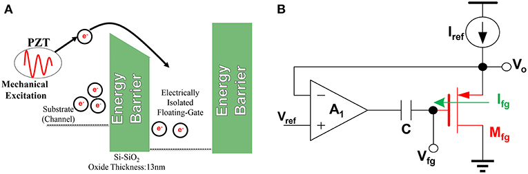
Figure 1. Circuit detail and illustration of Impact-Ionized Hot-Electron Injection (IIHEI) in Piezoelectric-Floating-Gate (PFG) sensors. (A) Illustration showing that mechanical excitation of a piezoelectric can propel electrons beyond an energy barrier. Electrons on their own will remain trapped between barriers. (B) The feedback amplifier, A1, enables linearized injection onto floating-gate, Mfg.
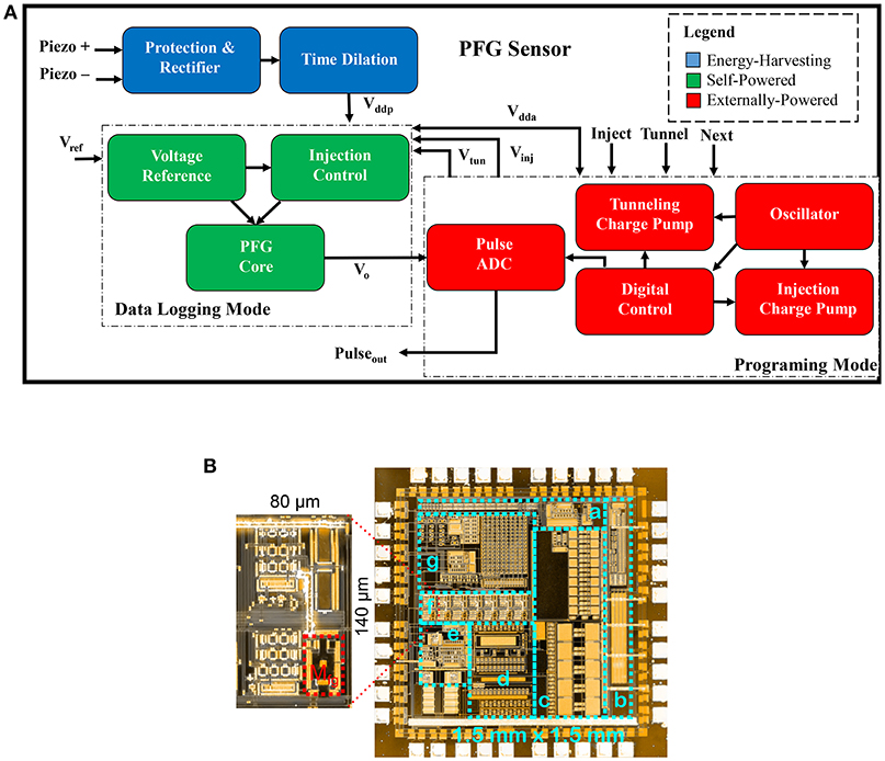
Figure 2. (A) Block diagram of PFG and (B) custom fabricated System-on-Chip micrograph. (A) A high-level overview of the components in a PFG sensor. (B) a. Digital Control, b. Oscillator, c. Charge Pumps, d. Protection, Rectifier, and Time Dilation, e. Pulse ADC, f. PFG Core, g. Voltage Reference and Injection Control. Zoomed inset shows a single channel of the PFG, with the floating-gate highlighted in red.
However, since floating-gate can only store a finite amount of charge, it will eventually saturate after a certain number of injection cycles; therefore, it is necessary to have a method for removal of charge to enable a reusable sensor. This leads to our third main principle, Fowler-Nordheim (FN) Tunneling, which occurs when a high-voltage is applied to the gate of the floating-gate PMOS. This large field potential induces a large amount of charge to leak out of a parasitic capacitance (Thomsen and Brooke, 1991). In our implementation, the tunneling operation is applied globally to all floating-gate channels present on the chip, and only if an external power source is available. This is in contrast to injection, which occurs on a channel-by-channel basis and when self-powered.
2.2. Sensor Architecture and Operation
Seven floating-gate transistors are integrated into a System-on-Chip (SOC) to create the PFG sensor platform used for continual monitoring of mechanical excitations. Each of these seven floating-gates are pre-programmed to have different activation thresholds (7.75, 8.22, 8.69, 9.15, 9.62, 10.09, and 10.56 V), resulting in each of the floating-gates only being injected if the piezoelectric input exceeds specific thresholds that were hardwired into the device. These thresholds were selected after consultation with domain experts regarding the expected response of strain-mode piezoelectrics when deployed on infrastructure. An overview of the general architecture of the device used for this case study can be seen in Figure 1B. As illustrated in the Figure 2A, the PFG has many modules in addition to the floating-gate sensor core, all of which have been previously reported in Huang et al. (2010, 2011), Aono et al. (2014), and Borchani et al. (2016) and therefore they will only be briefly touched on here in regards to their functionality in the PFG sensors operation.
The PFG has two main operational modes, which are distinguished by their powering modality. The first operational mode is the self-powered mode, during which the PFG behaves a self-powered data logger. This circuitry (see Figure 2A) is able to operate in a self-powered modality due to the fact that the sensing, processing and data-logging is all completed with pico-Watt power dissipation (Huang and Chakrabartty, 2011), that is provided by an input stimuli on the strain-mode piezoelectric transducer (Sarkar and Chakrabartty, 2013). After Vddp drops below approximately 6 V, the circuit is no longer able to operate due to the voltage dropping below the minimum threshold required to generate hot electrons through a PMOS. This determination of this value is was previously reported (Sarkar et al., 2013). Once this lower limit is reached, the circuit goes back to sleep and awaits the next mechanical excitation.
The second operational mode is the programming mode, which requires an external power supply. In the programming mode, the user is able to use a variety of digital commands to set the amount of charge that is stored on the floating-gates in preparation for a deployment. These three commands consist of injection, which adds charge to the gate, tunneling, which removes charge from the gate, and next, which changes the active floating-gate channel on the PFG. External power is also required to readout the values stored on each of the floating-gates. The value of each of these floating-gates can be read out by either sampling the analog voltage directly or by measuring the output of the Pulse ADC. The Pulse ADC measures the voltage Vo on the actively selected channel (see Figure 1B) and converts this voltage to a frequency value that is compatible with standard digital systems. This frequency value is used to determine the cumulative strain excitations that the piezoelectric transducer experienced during its deployment.
2.3. Laboratory Validation
Before deploying the PFG sensors into real-world situations, several laboratory tests were conducted to characterize the performance of the device and determine its aptitude at detecting and logging the strain applied to a piezoelectric material. Several tests were done to characterize the rate of injection in terms of both the Vref and the external tuning resistance used to set Vref. Plots showing the relationships between these three parameters can bee seen in Figure 3, where it can be seen that an increase of the external resistance results in a decrease in the Vref which results in a decrease in the rate of injection. In addition, due to the fact that these sensors are going to be deployed in a variety of environments, it is also important to characterize how the PFG is affected by temperature. Plots describing how the rate of injection and the performance of the pulse ADC can be seen in Figures 3G,H. The plot relating the output frequency of the pulse ADC to Vo can be seen in Figure 4. Despite the fact that differing values of the input voltage can have the same frequency output, these values can still be differentiated by observing their duty cycle, as explained in Aono et al. (2018) which shows the duty cycle along with the output frequency. In order to validate the sensors ability to detect strain, several testing methodologies were used. These methodologies were previously reported in Hasni et al. (2017d), with a setup for a four-point bending test presented in Figure 5. From this test, it was verified that the PFG was indeed able to measure and log variations in the strain applied to a piezoelectric transducer. Using the cumulative strain history, analytic and numerical methods are applied to ascertain the structural health (Hasni et al., 2017b; Jiao et al., 2017).
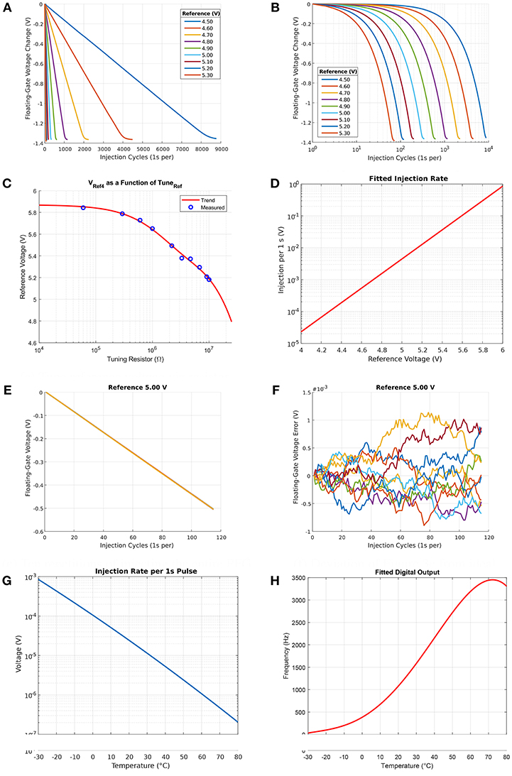
Figure 3. Laboratory verification and characterization of PFG sensor functionality. (A) Linear injection, (B) Log-scale of (A), (C) Tune reference voltage via resistor, (D) Tune injection rate via reference voltage, (E) Ten repetitions of injecting the entire PFG, (F) Deviation of (E) from ideal, (G) Temperature dependence of injection rate, and (H) Temperature dependence of ADC.
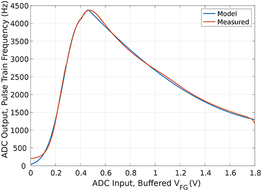
Figure 4. Input-output characteristic of the pulse encoder ADC, peak output frequency occurs near 470 mV. Though not monotonic in frequency output, the duty cycle of the pulses is different on either side of the peak output frequency.
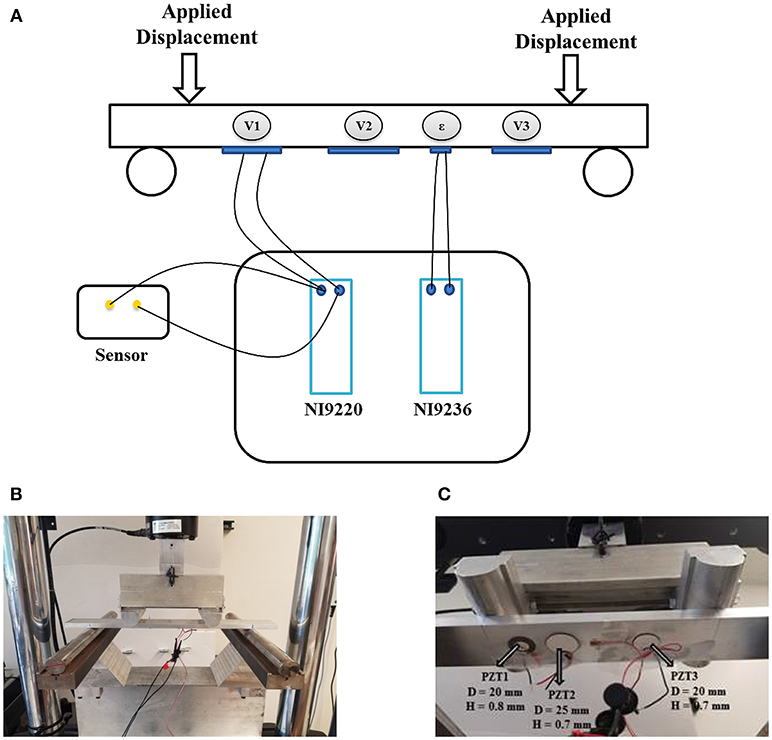
Figure 5. Diagram and images of the test setup used for laboratory validation. (A) A diagram depicting the four-point bending test, with piezoelectrics affixed to the bottom of a plate. The voltage response is measured using National Instruments devices. (B) The picture of our actual apparatus. (C) Close-up of the affixed transducers.
3. Transducer Selection
3.1. Strain, Frequency, and Temperature Calibration
Based on numerical simulations and feedback from previous measurements on the Mackinac Bridge, we estimated the anticipated strain response levels for the targeted areas to monitor. The type of transducer that is coupled with the PFG sensor from section 2 directly affects the amount of information that the sensor logs since each piezoelectric responds differently to ambient excitations when attached to steel in a strain sensing modality (Hasni et al., 2017d, 2018a). Based on the numerical simulations of the responses from different transducers, three piezoelectric ceramic discs were identified and evaluated in a controlled setting to investigate their behavior under anticipated deployment conditions. Commercially available foil strain gages were also used in paralegal throughout evaluation to provide a ground truth comparison for the applied stains. In Figure 5, we present a diagram of the experimental apparatus setup, a picture of the actual implementation, and a close-up of the piezoelectric ceramic discs attached to a test specimen. As shown in Figure 5B, we perform a four-point bending test on an aluminum specimen by applying controlled repetitive strains. The piezoelectric ceramic discs (PZTs) were sourced from STEMINC Inc. The relevant parameters of each of the PZT discs are as follows, PZT1 and PZT3 have the same diameter of 20 mm, while PZT2 is larger with a diameter of 25 mm. Both PZT2 and PZT3 have the same material thickness (height) of 700 μm, and PZT1 has a larger height of 800 μm. Additional properties available upon request.
In a four-point bending test, the strain is constant between the load application points, with the controlled strain amplitude given as:
where F is the applied force, A is the coordinate of the first inner clamp relative to the first outer clamp, b is the width of the specimen under test, h is the height, and E is the elastic modulus. The voltages generated from the PZTs are logged using a high input impedance (~1 GΩ) data logging device (National Instruments - NI9220). Similarly, the strain gage reference response is logged using an NI9236. Each PZT is connected to a PFG sensor as depicted in the diagram of Figure 5A. The testing load is applied using an MTS servo hydraulic machine in displacement-controlled mode, with a cyclic displacement applied for each test iteration. The applied load is slowly increased, while monitoring the reference strain until the first floating-gate transistor is activated as described in section 2. Once a target load to apply was determined, the displacement was applied for 40 cycles. The resulting PFG memory for four different chips is presented in Figure 6A. Due to fabrication mismatch in the CMOS, not all chips will behave exactly the same. This is evidenced by the fact that the same loading activated most of the chips, but one of them did not activate at the given load. The procedure of of determining the activation load and cyclically loading was also done for the second (Figure 6B), third (Figure 6C), and fourth (Figure 6D) floating-gates on a PFG. In those tests, all four test samples were in close agreement for the load required to active. Moreover, Figure 6 demonstrates that the PFG data-logging has a linear trend that is repeatable and predictable. Based on these observations, PZT1 and PZT3 respond to a strain range of 75 μϵ to 220 μϵ, while PZT2 is effective at the range from 50 to 100 μϵ. The combination of all of the PZTs is designed to cover the entire range between (50 μϵ and 250 μϵ).
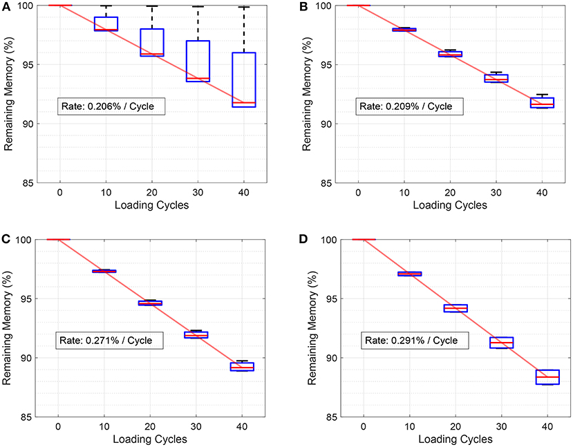
Figure 6. Measured injection profiles for a prototype sensor on four separate floating-gates. Excluding one outlier, all four are in close agreement, and the median response follows a linear trend as expected. (A) Strain level 1, (B) Strain level 2, (C) Strain level 3, and (D) Strain level 4.
Additionally, the dynamic strains and vibrations on the Mackinac bridge can contain components in the sub-Hz region. In order to make sure this information is captured, additional testing was conducted on PZT2 (high sensitivity) with loading cycle frequencies of 400 and 500 mHz. The same testing procedure described above is maintained, and the recorded results are presented in Table 1. For the sub-Hz region, the sensors monitor events ranging from 70 to 250 μϵ. Another important consideration for the deployment of the PFG sensors on the Mackinac Bridge is the significant variation in ambient temperatures that are observed in northern Michigan. Similar to the deployment conditions, a rubberized flexible sealant layer was sprayed on the piezoelectric discs. The coating provides protection against water, humidity, air, and other environmental factors that could cause damage and corrosion. The testing procedure described above is repeated for a 500 mHz loading frequency temperature was varied from −20 to 20 °C. The collected data are shown in Table 2. The expected performance variations for PZT2 at very low temperatures are characterized when coupled with the PFG sensor. Only a slight variation is documented for the first stage memory cells corresponding to low strain levels.
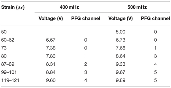
Table 1. Measured PZT strain-voltage and PFG activation vs. frequency.
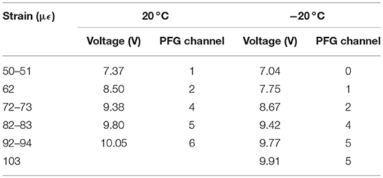
Table 2. Measured PZT strain-voltage and PFG activation vs. temperature.
3.2. Cabling Effects
In laboratory testing, we used grabber wires or alligator clips for interfacing the PFG sensors with the PZT transducers, yet when moving to an actual field deployment, where the setup will be exposed to the elements, a more robust interconnect is required. The type of wiring could have a noticeable affect on the sensor performance, as the capacitance and electrical resistance of the wires could vary depending on the gauge, shielding, or wire arrangement of a cable. We sourced the C0744A.41.10 multi-conductor (eight wires) cable from General Cable, which uses 24 AWG stranded copper as the conducting wires with 0.0320 in of poly-vinyl chloride (PVC) insulation. This cable has a rated operational temperature range of −20 to 80 °C, an inter-wire capacitance of 30 pF/ft, and a wire-to-shield capacitance of 55 pF/ft. We specifically chose this cable for it's low-cost and high availability (it is similar to cables used for Ethernet), as well as the low capacitance offered by thin conductors. To test the effects of a more robust cable, the C8101.41.03, also from General Cable, was evaluated. The cable only has two conductors of 18 AWG each and a much more robust 0.0160 in Fluorinated Ethylene Propylene (FEP) jacket insulation with operational ratings of -40 °C to 150 °C and inter-wire capacitance of 51 pF/ft and wire-to-shield capacitance of 91 pF/ft.
Each cable was tested using the low input frequency and room temperature configuration of the four-point bending test that is described above. We recorded the threshold strain levels and voltage generated and found that for PZT2 the average difference in PFG channel thresholds between the two cables was about 0.86 μϵ or 15.7 mV. Similarly, the average differences for PZT3 were 1.85 μϵ and 10.0 mV, allowing us to conclude that the cables had negligible effect on the threshold performance of the PFG sensors. Although the performance was not degraded by the choice of cabling, it is important to source cables that are rated for the expected deployment environment.
4. System Design for Deployment
The Mackinac Bridge is the gateway to the north that connects the upper and lower peninsulas of Michigan in the United State of America. When construction was completed in 1957, it claimed the title of longest suspension bridge and was regarded as one of the greatest engineering feats to date. Decades later, it remains the longest suspension bridge in the western hemisphere with a total structure length of 3.038 m (26,372 ft), a deck width of 20.9 m (68.6 ft), and peak tower height of 168 m (552 ft). It's scale provides an excellent venue for testing our bridge sensing platform, especially considering the harsh climate that the sensors will need to endure, with months of sub-zero weather anticipated.
In earlier deployments of the PFG for pavement monitoring applications, we demonstrated the feasibility of using a backscatter RF interface for data retreival (Huang and Chakrabartty, 2012; Chakrabartty et al., 2013; Aono et al., 2016). However, those communication methods are not optimal for steel-dense structures, especially considering that the sensors could be placed on elements of the bridge that are not near the road surface. Therefore, we coupled the self-powered PFG sensor to an active Radio Frequency (RF) communication link leading to a quasi-self-powered platform (Aono et al., 2017; Aono, 2018; Kondapalli et al., 2018).
4.1. First Deployment
Before the 2016 winter season, we deployed an initial prototype on the bridge to get a rough indication of the environmental conditions that sensors would be exposed to throughout their deployment lifetime. The initial prototype was designed to test our assumptions about appropriate procedures for developing a quasi-self-powered platform.
The initial prototype had three PFG sensors, each attached to either PZT1, PZT2, or PZT3 from section 3. Each of the three PFG sensors were connected to an off-the-shelf RF Microcontroller (MCU) from Texas Instruments (TI) that was able to collect data from the PFGs and wirelessly transmit it back to a moving vehicle on the bridge. An image of the first version of this prototype can be seen in Figure 7, with specifications given in Table 3. Initial data collected from each of the three PFGs provided insight into their efficacy and demonstrated the viability of the wireless interface. However, upon returning to the installation site after the winter, we found that the initial prototype had failed due to moisture entering the encapsulated prototype. This initial prototype and deployment gave us the following information:
• The PFG was able to cumulatively record strain events
• PZT2 provided the best data
• A majority of the power was used to provide a low-latency wireless interface
• Data collection does not need to occur frequently
• More than one layer of weather-proofing is required
• Alkaline batteries would not match the target lifespan.
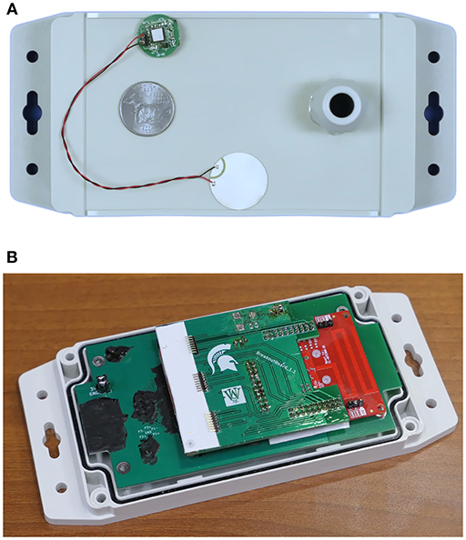
Figure 7. Initial wireless sensor box that was installed in autumn of 2017 and failed during the 2017–2018 winter due to water ingress. This box was deployed as a means to provide rapid-verification of the PZT selection and PFG data-logging capability. (A) Initial prototype's weather proofing enclosure, a sample PFG sensor and PZT are shown next to a U.S. quarter for scale. (B) Launchpad with adapter PCB to interface with three PFG sensors, black sections are weatherproofed debugging pads, and the batteries are mounted on the underside of the PCB.
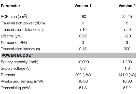
Table 3. Prototype specifications.
4.2. Second Deployment
Taking into account the lessons learned from the initial prototype, we designed an improved version. The improved sensor assembly is shown as Figure 8A and the weatherproof enclosure is presented in Figure 8B. A custom PCB that has a built-in PCB antenna connected to TI's CC1310 RF MCU was designed. As in the initial prototype, this component enables the active wireless communication and interfaces with up to three PFG sensors per box. Each PFG is soldered onto an individual daughterboard PCB that can be easily swapped in or out on the RF motherboard via flexible flat cables. This capability allows for rapid replacement of PFG sensors if we need to change the injection rate, diagnose a failure, or reset the floating-gate memory (though possible through the wireless communication, we removed this option to prevent malicious tampering of data at this stage).
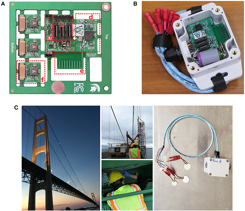
Figure 8. Second version of the sensor platform, deployed for testing in spring of 2017 and still responding in autumn of 2018. (A) Custom PCB with (a) Sleep-mode timer, (b) Connectors for PFG and piezo, (c) Battery Management, (d) RF MCU, (e) PCB Antenna, and (f) PFG modules. (B) Weatherproof housing with cabling, a batteries mounted, and the RF PCB installed. PFG module not mounted, and the lid is removed for this image. (C) Pictures showing the Mackinac Bridge, installation of the second version, and a mock-up of how the sensor platform is affixed to steel plates.
The CC1310 from TI is a commercial off-the-shelf RF MCU that enables wireless communication in the 915 MHz Industrial, Scientific, and Medical radio band (ISM band), while simultaneously offering capabilities typical of MCUs, such as programmable general purpose input/output pins (GPIO), clock timing with ms precision, and user-programmable firmware. In this second prototype, the GPIOs are used to give a rising edge to pre-determined pins of the PFG to send commands such as: increment selected channel, reset all channels, program current channel, enable readout, and reset PFG state machine. The CC1310 was configured for an average active supply current draw of 12 mA with wireless communication sensitivity below -110 dB m, estimates using TI datasheets suggest that this setup could yield wireless ranges in excess of 1 km even with a low efficiency PCB antenna. Indeed, we were able to communicate with sensors deployed on the steel structure of the bridge using a CC1310 connected to a PC on the road surface. The data from sensors are logged on the PC for later analysis.
The RF motherboard includes a buck converter to extract more energy from the batteries before the system stops responding due to low supply voltage. Additionally, a nano-power timer (TI TPL5111) disconnects all electronics from the battery by turning off a load switch. This user-configurable timer was set for 5 min, therefore the prototype would be unresponsive for 5 min at a time, but would only lose a miniscule amount of supply current to leakage, measured to be less than 50 nA. On the initial startup, the RF MCU is programmed to go into a “search” mode where it will listen for an interrogator (i.e., an operator that has a similar RF board connected to their PC which is asking for data). Only if an interrogator is detected will the prototype sample and transmit the PFG sensor data. This is done since the energy cost of a transmission is much larger than receiving, in particular the CC1310 was configured to listen for an interrogator for 6 s at a time with an average supply current of 225 μA while a transmission can take as long as 13.5 s with an order of magnitude larger supply current of 2.5 mA. Based on these supply currents, we can estimate typical supply currents of:
If we collect data from these sensor boxes twice a day (that is, 1% of the time), and use a ½ AA battery with 1.2 Ah of capacity, then it would remain operational for:
In a more traditional sensing platform, the MCU would need to periodically poll the sensors to collect data, which would prevent them from operating at the nA range that our prototype does. Moreover, in such polling methods, the collected data would not represent the entire history of the structure's health since these sensors are not continuously sampling and are only collecting data when the sensor node wakes up to transmit (Chakrabartty et al., 2013). Due to the reduction in energy requirements that were realized from the periodic transmission, a more robust battery (Tadiran's lithium thionyl chloride) chemistry could be employed. Similar batteries have demonstrated 40 years of operating life, and accelerated testing in a temperature chamber gave results consistent with our previously outlined assumptions about battery life.
The cables of the second prototype were upgraded to a six conductor cable with 24 AWG wires (General Cables, C3029.41.86) which has a flouropolymer jacket insulation that is rated for operation between −40 and 150°C and has a reduced capacitance of 13 pF/ft between conductors and 23 pF/ft conductor-to-shield capacitance. This allows the cable gland to be given a tighter fit, we also filled the inside of the gland with a copious amount of sealant.The water-tightness of this setup was verified with a one week submersion test with daily agitation of the water. The inside of the box did not show any signs of being compromised, and the non-conformal coated electronics still responded after being removed from the water bath. In the final deployed prototype, all electrical components in the box were treated with a silicone conformal coating, which by itself provides protection against water or ice causing electrical shorts. The enclosure was reduced in size to 59 × 94 × 35 mm3 and the material was also upgraded from an economical plastic to a more robust UV-stabilized polycarbonate.
5. Field Deployment: Mackinac Bridge
The improved prototype was deployed in May of 2017 (shown in Figure 8C), and in this section we present two particular events that show the data-logging capability of the proposed quasi-self-powered platform. It is shown that the PFG sensors were able to detect the increase in traffic due to the influx of bridge crossings that occurs during the annual Mackinac Bridge Labor Day Walk.
5.1. Data From 2017
Data were collected between May 25th and September 5th of 2017 and had a corrective factor applied (Aono et al., 2018). Based on the traffic patterns provided by the Mackinac Bridge Authority, an expected response model for the PFG sensor was developed using in-lab testing characterizations (Huang et al., 2011; Aono et al., 2014; Feng et al., 2015; Borchani et al., 2016). For the analysis presented here, we operate under the assumption that this model is ground truth since data from continuously powered commercial sensors is not available. The measured data from the PFG sensors were compared against the model, and the mean-squared deviation is given in a box-whisker plot as Figure 9. What we found is a deviation from the model around September 4th. This date coincides with the annual Mackinac Bridge Labor Day Walk, which drew a crowd of over 25,000 people (the Mackinac Bridge does not typically have foot traffic). It should be noted that the traffic pattern data used to generate the ground truth model did not include the traffic data from that specific date, as the supplied traffic data was in aggregate form, nor does it include any foot traffic. The observed deviation indicates the successful detection of traffic patterns using our sensor platform.
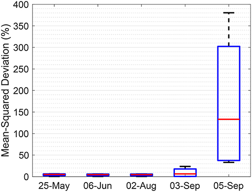
Figure 9. Variation of data collected from four sensors during 2017, as compared against vehicle traffic trends. A large deviation around September 4th (Labor Day Walk) is observed.
5.2. Focus on 2018 Labor Day Walk
After leaving the prototypes deployed on the bridge for the 2017–2018 winter season, they were still responding when we returned in the spring of 2018. Upon opening the boxes for inspection, we found that none of four units showed signs of water ingress or other hardware failures, and that the battery levels were also as expected based on our calculated operational lifespan of 23.5 yrs per ½ AA battery. The sensors remained operational through the summer season as well. Before the annual Mackinac Bridge Labor Day Walk for 2018, we replaced the PFG sensors in Box 12 with ones that would log data more quickly (as in Figure 3, we used a smaller external tuning resistor on the reference voltage generator) to see if we could replicate the results from 2017. We also translated the pulse encoder output frequency into the equivalent stored floating-gate charge, which we denote as the PFG Data in volts. The resulting data plots are given in Figure 10. Sensor 2 was consistently logging data, regardless of the traffic levels, which might be expected due to the placement of that PZT since it could be tracking the sway of the bridge from winds. According to the Mackinac Bridge Authority, it is typical for winds to cause horizontal sways, and if the placement of the PZT is correct, Sensor 2 could be logging such horizontal strains instead of the vertical strains that would be generated by passing traffic. The important aspect is to note that Sensors 1 and 3 did detect the variations in traffic around the Labor Day Walk.
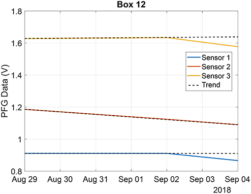
Figure 10. Sensors 1 and 3 show data-logging events around the 2018 Labor Day Walk (on September 03), Sensor 2 logging did not deviate due to the event. Trend line is expected data if no event occurred on September 03.
6. Discussion and Conclusion
In this paper we presented a quasi-self-powered structural health monitoring sensor system based on the Piezo-Floating-Gate (PFG) sensing technology. The sensor operates on a “sense now, retrieve-later” paradigm where cumulative strains are continuously logged and wirelessly retrieved and reconstructed at a later stage. In addition, we demonstrated how the system parameters could be optimized to ensure that the sensor is continuously operational for greater than 20 years. The proposed sensing technology was deployed at mesoscale on the Mackinac Bridge in northern Michigan and data were presented from two retrieval studies. Deployed prototypes have been demonstrated for over two years, with an estimated lifespan measured in decades. Across two years, we show that variations in traffic were successfully detected through this sensing technology. We anticipate that the life-span of the sensor would ultimately be determined by components of the prototype (capacitors, PZT, weatherproof seals, etc.) besides the battery, which is a limiting factor for many SHM WSN. This thereby demonstrates the utility of our quasi-self-powered approach for long-term sensing. One of the new research directions would be to reduce the latency of wireless transmissions and to create a network of the quasi-self-powered sensor prototypes. In this regard, it might be beneficial to use a combination of short-term energy storage solutions like super-capacitors with the long-term energy storage, such as the embedded batteries used in this work. The super-capacitor could then be periodically charged using energy harvested from available ambient sources like vibration or solar. Accordingly, a power-management unit on the PFG sensor could switch between a high-power and a low-power mode.
Data Availability
The datasets generated for this study are available on request to the corresponding author. Data from the bridge (Figures 9 and 10) cannot be shared with any third party without express permission from the Mackinac Bridge Authority.
Author Contributions
KA and HH drafted an initial manuscript. NL and HH determined piezoelectric characteristics. KA, OP, and SC designed and tested the PFG sensor. KA, NL, and SC planned the deployment. KA, NL, and HH calibrated the Piezo+PFG system. All authors contributed to the final manuscript.
Funding
This material is based upon work supported by the National Science Foundation under Grant Nos. DGE-0802267, DGE-1143954, CNS-1646380, and CNS-1645783. Any opinions, findings, and conclusions or recommendations expressed in this material are those of the author(s) and do not necessarily reflect the views of the National Science Foundation. The presented work was supported in part by a USDoT contract (DTFH6113H00009). Authors thank the Mackinac Bridge Authority for their continued assistance in carrying out this work.
Conflict of Interest Statement
SC and NL have financial ownership in Piezonix LLC, a for-profit entity engaged in the commercialization of the PFG sensing technology.
The remaining authors declare that the research was conducted in the absence of any commercial or financial relationships that could be construed as a potential conflict of interest.
References
Alavi, A. H., Hasni, H., Lajnef, N., Chatti, K., and Faridazar, F. (2016). An intelligent structural damage detection approach based on self-powered wireless sensor data. Autom. Construct. 62, 24–44. doi: 10.1016/j.autcon.2015.10.001
Aono, K. (2018). Nanopower Analog Frontends for Cyber-Physical Systems. Ph.D. thesis, Washington University in St. Louis.
Aono, K., Covassin, T., and Chakrabartty, S. (2014). “Monitoring of repeated head impacts using time-dilation based self-powered sensing,” in IEEE International Symposium on Circuits and Systems, ISCAS 2014 (Melbourne, VIC), 1620–1623.
Aono, K., Hasni, H., Pochettino, O., Lajnef, N., and Chakrabartty, S. (2018). “Quasi-self-powered infrastructural internet of things: the mackinac bridge case study,” in Proceedings of the 2018 on Great Lakes Symposium on VLSI, GLSVLSI '18 (Chicago, IL), 335–340.
Aono, K., Kondapalli, S. H., and Pochettino, O. (2017). “Self-powered sensors to facilitate infrastructural internet-of-things for smart structures,” in The 13th International Workshop on Advanced Smart Materials and Smart Structures Technology (Tokyo), 1–8.
Aono, K., Lajnef, N., Faridazar, F., and Chakrabartty, S. (2016). “Infrastructural health monitoring using self-powered internet-of-things,” in IEEE International Symposium on Circuits and Systems, ISCAS 2016 (Montréal, QC), 2058–2061.
Bennett, R., Hayes-Gill, B., Crowe, J. A., Armitage, R., Rodgers, D., and Hendroff, A. (1999). “Wireless monitoring of highways,” in Smart Structures and Materials 1999: Smart Systems for Bridges, Structures, and Highways, Vol. 3671 (Newport Beach, CA: International Society for Optics and Photonics), 173–183. doi: 10.1117/12.348667
Borchani, W., Aono, K., Lajnef, N., and Chakrabartty, S. (2016). Monitoring of postoperative bone healing using smart trauma-fixation device with integrated self-powered piezo-floating-gate sensors. IEEE Trans. Biomed. Eng. 63, 1463–1472. doi: 10.1109/TBME.2015.2496237
Chakrabartty, S. (2010). Self-Powered Strain-Rate Sensor. Patent No. 7757565. East Lansing, MI: Board of Trustees Operating Michigan State University.
Chakrabartty, S. (2016). Self-Powered Strain-Gauge. Patent No. 9331265. East Lansing, MI: Board of Trustees Operating Michigan State University.
Chakrabartty, S., Feng, T., and Aono, K. (2013). “Gen-2 rfid compatible, zero down-time, programmable mechanical strain-monitors and mechanical impact detectors,” in Sensors and Smart Structures Technologies for Civil, Mechanical, and Aerospace Systems 2013 (San Diego, CA: International Society for Optics and Photonics). doi: 10.1117/12.2011956
Chakrabartty, S., Lajnef, N., Elvin, N., and Gore, A. (2011). Self-Powered Sensor. Patent No. 8056420. East Lansing, MI: Board of Trustees Operating Michigan State University.
Cho, S., Yun, C.-B., Lynch, J. P., Zimmerman, A. T., Spencer, B. F. Jr., and Nagayama, T. (2008). Smart wireless sensor technology for structural health monitoring of civil structures. Steel Struct. 8, 267–275. Available online at: https://www.researchgate.net/publication/285774152_Smart_Wireless_Sensor_Technology_for_Structural_Health_Monitoring_of_Civil_Structures
Chynoweth, A. G. (1958). Ionization rates for electrons and holes in silicon. Phys. Rev. 109, 1537–1540. doi: 10.1103/PhysRev.109.1537
Elvin, N. G., Lajnef, N., and Elvin, A. A. (2006). Feasibility of structural monitoring with vibration powered sensors. Smart Mater. Struct. 15, 1422–1429. doi: 10.1088/0964-1726/15/4/011
Feng, T., Aono, K., Covassin, T., and Chakrabartty, S. (2015). Self-powered monitoring of repeated head impacts using time-dilation energy measurement circuit. Trans. Biomed. Circ. Syst. 9, 217–226. doi: 10.1109/TBCAS.2015.2403864
Hasni, H., Alavi, A. H., Chatti, K., and Lajnef, N. (2017a). A self-powered surface sensing approach for detection of bottom-up cracking in asphalt concrete pavements: theoretical/numerical modeling. Construct. Build. Mater. 144, 728–746. doi: 10.1016/j.conbuildmat.2017.03.197
Hasni, H., Alavi, A. H., Jiao, P., and Lajnef, N. (2017b). Detection of fatigue cracking in steel bridge girders: a support vector machine approach. Archiv. Civil Mech. Eng. 17, 609–622. doi: 10.1016/j.acme.2016.11.005
Hasni, H., Alavi, A. H., Jiao, P., Lajnef, N., Chatti, K., Aono, K., et al. (2017c). A new approach for damage detection in asphalt concrete pavements using battery-free wireless sensors with non-constant injection rates. Measurement 110, 217–229. doi: 10.1016/j.measurement.2017.06.035
Hasni, H., Alavi, A. H., Lajnef, N., Abdelbarr, M., Masri, S. F., and Chakrabartty, S. (2017d). Self-powered piezo-floating-gate sensors for health monitoring of steel plates. Eng. Struct. 148, 584–601. doi: 10.1016/j.engstruct.2017.06.063
Hasni, H., Aono, K., Lajnef, N., Chakrabartty, S., and Faridazar, F. (2018a). “Toward autonomous self-powered self-sensing civil infrastructures,” in NDE/NDT for Structural Materials Technology for Highway Bridges (SMT) and the International Symposium on Non-Destructive Testing in Civil Engineering (NDT-CD) (New Brunswick, NJ: SMT and NDT-CE).
Hasni, H., Chatti, K., Lajnef, N., Chakrabartty, S., and Aono, K. (2017e). “Damage progression identification in asphalt concrete pavements: a smart self-powered sensing approach,” in Advances in Materials and Pavement Prediction, International Conference on Advances in Materials and Pavement Performance Prediction (AM3P 2018) (Doha), 1–10.
Hasni, H., Jiao, P., Alavi, A. H., Lajnef, N., and Masri, S. F. (2018b). Structural health monitoring of steel frames using a network of self-powered strain and acceleration sensors: a numerical study. Autom. Construct. 85, 344–357. doi: 10.1016/j.autcon.2017.10.022
Hasni, H., Lajnef, N., Alavi, A. H., Aono, K., and Chakrabartty, S. (2018c). “Local-global damage identification approach using hybrid network of self-powered sensors,” in The 7th World Conference on Structural Control and Monitoring (7WCSCM) (Qingdao), 1–8.
Huang, C., and Chakrabartty, S. (2011). Compact self-powered CMOS strain-rate monitoring circuit for piezoelectric energy scavengers. Electron. Lett. 47, 277–278. doi: 10.1049/el.2010.3430
Huang, C., and Chakrabartty, S. (2012). An asynchronous analog self-powered CMOS sensor-data-logger with a 13.56 MHz RF programming interface. IEEE J. Solid State Circ. 47, 476–489. doi: 10.1109/JSSC.2011.2172159
Huang, C., Lajnef, N., and Chakrabartty, S. (2010). Calibration and characterization of self-powered floating-gate usage monitor with single electron per second operational limit. IEEE Trans. Circ. Syst. I Reg. Pap. 57, 556–567. doi: 10.1109/TCSI.2009.2024976
Huang, C., Sarkar, P., and Chakrabartty, S. (2011). Rail-to-rail, linear hot-electron injection programming of floating-gate voltage bias generators at 13-bit resolution. J. Solid State Circ. 46, 2685–2692. doi: 10.1109/JSSC.2011.2167390
Jiao, P., Borchani, W., Alavi, A. H., Hasni, H., and Lajnef, N. (2018). An energy harvesting and damage sensing solution based on postbuckling response of nonuniform cross-section beams. Struct. Control Health Monit. 25:e2052. doi: 10.1002/stc.2052
Jiao, P., Borchani, W., Hasni, H., and Lajnef, N. (2017). A new solution of measuring thermal response of prestressed concrete bridge girders for structural health monitoring. Meas. Sci. Technol. 28:085005. doi: 10.1088/1361-6501/aa6c8e
Kondapalli, S. H., Pochettino, O., Aono, K., and Chakrabartty, S. (2018). “Hybrid-powered internet-of-things for infrastructure-to-vehicle communication,” in 2018 IEEE 61st International Midwest Symposium on Circuits and Systems (MWSCAS) (Windsor, ON).
Korhonen, I., and Lankinen, R. (2014). Energy harvester for a wireless sensor in a boiler environment. Measurement 58, 241–248. doi: 10.1016/j.measurement.2014.08.037
Lynch, J. (2004). “Overview of wireless sensors for real-time health monitoring of civil structures,” in Proceedings of the 4th International Workshop on Structural Control (New York, NY), 189–194.
Lynch, J. P. (2005). Design of a wireless active sensing unit for localized structural health monitoring. Struct. Control Health Monit. 12, 405–423. doi: 10.1002/stc.77
Lynch, J. P., Law, K. H., Kiremidjian, A. S., Kenny, T. W., Carryer, E., and Partridge, A. (2001). “The design of a wireless sensing unit for structural health monitoring,” in Proceedings of the 3rd International Workshop on Structural Health Monitoring (Stanford, CA: Stanford University), 12–14.
Lynch, J. P., and Loh, K. J. (2006). A summary review of wireless sensors and sensor networks for structural health monitoring. Shock Vibrat. Digest 38, 91–130. doi: 10.1177/0583102406061499
Mehta, D., Zhou, L., Aono, K., and Chakrabartty, S. (2018). “Self-powered sensing and time-stamping of tampering events,” in 2018 IEEE 61st International Midwest Symposium on Circuits and Systems (MWSCAS) (Windsor, ON).
Paek, J., Kothari, N., Chintalapudi, K., Rangwala, S., and Govindan, R. (2004). “The performance of a wireless sensor network for structural health monitoring,” in UCLA: Center for Embedded Network Sensing (UCLA), 1–12. Retreived from https://escholarship.org/uc/item/9bf7f3n5
Pasupath, P., Zhou, M. Z., Neikirk, D. P., and Wood, S. L. (2008). “Unpowered resonant wireless sensor nets for structural health monitoring,” in 2008 IEEE Sensors (Lecce), 697–700.
Rahimi, K., Diorio, C., Hernandez, C., and Brockhausen, M. D. (2002). “A simulation model for floating-gate mos synapse transistors,” in IEEE International Symposium on Circuits and Systems, 2002. ISCAS 2002 (Phoenix-Scottsdale, AZ).
Sackin, D. (1999). A Feasibility Study of Embedded Microdevices for Infrastructure Monitoring; Smart Aggregate for Concrete. Ph.D. thesis, A thesis submitted in partial fulfillment of the requirements for the degree of Master of Science. Carnegie Mellon University.
Sarkar, P., and Chakrabartty, S. (2013). Compressive self-powering of piezo-floating-gate mechanical impact detectors. IEEE Trans. Circ. Syst. I Reg. Pap. 60, 2311–2320. doi: 10.1109/TCSI.2013.2245472
Sarkar, P., Huang, C., and Chakrabartty, S. (2013). An ultra-linear piezo-floating-gate strain-gauge for self-powered measurement of quasi-static-strain. IEEE Trans. Biomed. Circuits Syst. 7, 437–450. doi: 10.1109/TBCAS.2012.2220764
Sirohi, J., and Chopra, I. (2000). Fundamental understanding of piezoelectric strain sensors. J. Intell. Mater. Syst. Struct. 11, 246–257. doi: 10.1106/8BFB-GC8P-XQ47-YCQ0
Spencer, B. Jr, Ruiz-Sandoval, M. E., and Kurata, N. (2004). Smart sensing technology: opportunities and challenges. Struct. Control Health Monit. 11, 349–368. doi: 10.1002/stc.48
Srinivasan, V., Serrano, G. J., Gray, J., and Hasler, P. (2007). A precision CMOS amplifier using floating-gate transistors for offset cancellation. IEEE J. Solid State Circ. 42, 280–291. doi: 10.1109/JSSC.2006.889365
Tam, S., Ko, P.-K., and Hu, C. (1984). Lucky-electron model of channel hot-electron injection in mosfet's. IEEE Trans. Elect. Dev. 31, 1116–1125.
Thomsen, A., and Brooke, M. A. (1991). A floating-gate mosfet with tunneling injector fabricated using a standard double-polysilicon CMOS process. IEEE Elect. Dev. Lett. 12, 111–113.
Ueno, K. (2010). CMOS Voltage and Current Reference Circuits consisting of Subthreshold MOSFETs–Micropower Circuit Components for Power-Aware LSI Applications– InTech.
Watters, D. G., Jayaweera, P., Bahr, A. J., Huestis, D. L., Priyantha, N., Meline, R., et al. (2003). “Smart pebble: wireless sensors for structural health monitoring of bridge decks,” in Smart Structures and Materials 2003: Smart Systems and Nondestructive Evaluation for Civil Infrastructures, Vol. 5057 (San Diego, CA: International Society for Optics and Photonics), 20–29.
Whelan, M. J., Gangone, M. V., Janoyan, K. D., and Jha, R. (2009). Real-time wireless vibration monitoring for operational modal analysis of an integral abutment highway bridge. Eng. Struct. 31, 2224–2235. doi: 10.1016/j.engstruct.2009.03.022
Yu, Y., Kang, W.-H., Zhang, C., Wang, J., and Ou, J. (2015). A stochastic analysis framework for a steel frame structure using wireless sensor system measurements. Measurement 69, 202–209. doi: 10.1016/j.measurement.2015.03.022
Yun, C.-B., and Min, J. (2011). Smart sensing, monitoring, and damage detection for civil infrastructures. KSCE J. Civil Eng. 15, 1–14. doi: 10.1007/s12205-011-0001-y
Yun, G. J., Lee, S.-G., Carletta, J., and Nagayama, T. (2011). Decentralized damage identification using wavelet signal analysis embedded on wireless smart sensors. Eng. Struct. 33, 2162–2172. doi: 10.1016/j.engstruct.2011.03.007
Zhou, L. (2018). Self-powered Time-Keeping and Time-of-Occurrence Sensing. Ph.D. thesis, Washington University in St. Louis.
Zhou, L., Aono, K., and Chakrabartty, S. (2018). A CMOS timer-injector integrated circuit for self-powered sensing of time-of-occurrence. IEEE J. Solid State Circ. 53, 1539–1549. doi: 10.1109/JSSC.2018.2793531
Keywords: structural health monitoring, quasi-self-powered sensing, piezo-floating-gate, mackinac bridge, energy harvesting, machine learning
Citation: Aono K, Hasni H, Pochettino O, Lajnef N and Chakrabartty S (2019) Quasi-Self-Powered Piezo-Floating-Gate Sensing Technology for Continuous Monitoring of Large-Scale Bridges. Front. Built Environ. 5:29. doi: 10.3389/fbuil.2019.00029
Received: 01 December 2018; Accepted: 20 February 2019;
Published: 26 March 2019.
Edited by:
Branko Glisic, Princeton University, United StatesReviewed by:
Anastasiia O. Krushynska, University of Trento, ItalyLuigi Di Sarno, University of Sannio, Italy
Copyright © 2019 Aono, Hasni, Pochettino, Lajnef and Chakrabartty. This is an open-access article distributed under the terms of the Creative Commons Attribution License (CC BY). The use, distribution or reproduction in other forums is permitted, provided the original author(s) and the copyright owner(s) are credited and that the original publication in this journal is cited, in accordance with accepted academic practice. No use, distribution or reproduction is permitted which does not comply with these terms.
*Correspondence: Shantanu Chakrabartty, c2hhbnRhbnVAd3VzdGwuZWR1