 António Barrias
 Joan R. Casas
 Sergi Villalba2
- 1Department of Civil and Environmental Engineering, Technical University of Catalonia, Polytechnic University of Catalonia (UPC), Barcelona, Spain
- 2Department of Engineering and Construction Projects, Technical University of Catalonia, Polytechnic University of Catalonia (UPC), Barcelona, Spain
This document showcases the latest research conducted within UPC–BarcelonaTech on the performance of distributed optical fiber sensors (DOFS), more specifically the case of the optical backscattered reflectometry (OBR) system, in the structural health monitoring (SHM) of bridges, and large scale structures. This technology has demonstrated promising results for monitoring applications in a wide range of fields but due to its novelty, still presents several uncertainties which prevent its use in a more systematic and efficient way in civil engineering infrastructures, being this even more evident in the case of concrete structures. Therefore, different laboratory experimental campaigns were devised where multiple aspects of the instrumentation of DOFS technology in civil engineering applications were assessed and scrutinized. Such as the study of new implementation methods, comparison, and performance analysis of different bonding adhesives and spatial resolution. Additionally, the fatigue performance of this sensing typology was also assessed. Furthermore, the use of the OBR system technology was applied in a real world structure in Barcelona, Spain, where new challenging conditions had to be addressed. Consequently, with this work, different conclusions are obtained related to the proficiency and limitations on the use of this particular type of optical sensing system in concrete structures.
Introduction
When dealing with civil engineering infrastructures there is a great number of external events that can induce damage and degradation to a structure such as fatigue loading, corrosion, overloading, natural hazards, and innate passage of time, compromising in this way their consequently the safety of its users. As of 2017, in the United States alone, the average bridge is 43 years old and 9.1% of the total number of bridges were deemed structurally deficient. As a result, an average of 188 million trips are performed daily across these structurally deficient bridges and the most recent estimate projects the backlog of rehabilitation projects for these infrastructures at $123 billion (ASCE, 2017).
Despite this considerable amount of investment required to improve the condition of these structures, there is only a limited amount of funds available. Consequently, the development of measures that extend the service life of civil engineering infrastructures are of great importance. In this way, assessment and maintenance strategies that are able to target and identify those structures in most need of attention are highly in demand.
It is in this context that the field of Structural Health Monitoring (SHM) has been widely studied and advanced for the past few decades. Nonetheless, unfortunately, SHM has not yet been practiced in a large scale and in a regular manner in civil engineering structures. One of the reasons being that there is still a deficit of reliable and affordable generic monitoring solutions (Glisic et al., 2013).
Consequently, optical fiber sensors (OFS) have been one the most popular researched and practiced sensing technologies within SHM applications due to its many inherent advantages when compared with the more traditionally and commonly used electric based sensors. Some of these advantages are related with their immunity to electromagnetic interference enabling in this way noise reduced measurements, the capability to withstand a wide range of temperature variations, chemically inert and also being small and lightweight which facilitates its handling and transport (Casas and Cruz, 2003). Notwithstanding, this technology has been mostly applied through the use of Fiber Bragg Grating (FBG) sensors (Ferdinand, 2014), which are point or discrete sensors.
However, for a great number of applications, more particularly in the case of large-scale infrastructures, the number of point sensors necessary to obtain a complete and global strain monitoring, becomes impractically high. Additionally, for the specific case of concrete structures, where beforehand, it is practically impossible to know with certainty the exact location of possible damage and crack formations, these point sensors present serious limitations. Moreover, in practical terms, a large number of sensors present the difficulty of requiring an associated large number of connecting cables making all the monitoring system more complex. It is in this way that distributed optical fiber sensors (DOFS) provide a unique advantage allowing the strain and temperature monitoring of virtually every cross-section of the element where it is bonded to, requiring the use of just up to one single sensor and with it, one connecting cable.
Distributed Optical Fiber Sensors
Due to the novelty of this technology, the use of DOFS in civil engineering infrastructures SHM is still a relatively recent practice. These sensors share the same advantages of the other OFS but as mentioned before present the unique advantage of enabling the monitoring over greater length extents and with a very short distance between each measuring point, in the order of millimeters.
These sensors can be bonded or embedded to the structure to be monitored and when temperature or strain variations occur, these changes are going to be transmitted from the material to the sensor, which then generates a deviation of the scattered signal, which is being reflected within the fiber cable core. This scattering phenomenon is the basis behind the distributed optical fiber sensing, and defined by the interaction between the emitted light and the physical optical medium. Three scattering processes occur that can be used to obtain distributed strain and/or temperature measurements, namely the Raman, Brillouin, and Rayleigh scattering (Barrias et al., 2016).
Raman scattering is highly dependent of temperature variations, which has led to some applications in civil engineering SHM but has been more typically used in other fields (Barrias et al., 2018).
Brillouin, on the other hand has been the most studied and used scattering technique for distributed sensing in civil engineering structures monitoring. This is a consequence of its extended measurement range capability, which allows its use in applications where monitoring distances in the order of kilometers are present. This technique was initially introduced with the use of optical time domain reflectometry (OTDR) which has an inherent low spatial resolution (of around 1 m), which is not ideal for crack detection applications. More recently, this has been improved through the development of the Brillouin optical time domain analysis (BOTDA) which relatively enhances the achievable spatial resolution (Glišić et al., 2007; Ravet et al., 2009; Glisic and Inaudi, 2012).
Finally, the Rayleigh scattering based DOFS are currently limited to a sensing range of 70 m but provide a significant high spatial resolution of 1 mm, making it ideal for the use of damage monitoring such as crack detection in concrete structures. This is achieved through the use of swept wavelength interferometry (SWI) to measure the Rayleigh backscatter as a function of length.
The optical backscattered reflectometry (OBR) system based on the Rayleigh OFDR (Figure 1), is composed by an active part which sends a laser light through an optical fiber, and a passive part, where the light is reflected by the intrinsic variations along the fiber length (Samiec, 2012). This pattern of the reflections and the corresponding time of flight of the light is measured and stored, acting as a unique fingerprint for each fiber. When an external stimulus (like strain or temperature variation) happens, a temporal and spectral shift in the local Rayleigh backscatter pattern occurs. This new reflection pattern is then compared with the original one providing the variation and evolution of generated strains along the entire length of the fiber due to this external stimulus (Grave et al., 2015). More detailed information of this technology can be consulted in Barrias et al. (2016).
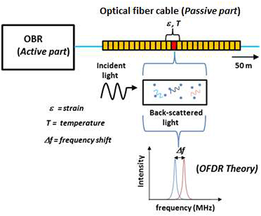
Figure 1. Measuring process by OBR system.
In this context, the capabilities and potential of the OBR system can be presented as a promising alternative for crack detection in concrete structures. This paper summarizes the work carried out in a series of laboratory tests and application to a real bridge by the research group with the objective of a better application and more reliable interpretation of the results in order to establish more robust and confident guidelines for future and wider application.
Laboratory Experiments
Currently, one of the major concerns related to the use of this technology is the strain transfer effectiveness between sensor and substrate material. When the sensors are bonded on the surface of the structural element, the challenge presented by the specific case of concrete structures due to the roughness and heterogeneity of its surface needs also to be considered. Hence, the study and identification of the optimal bonding adhesive and alternative installation methods for these applications becomes essential for a more widespread use of this technology in current and future concrete structures. Additionally, an important lack of applications is observed regarding the long-term performance (fatigue behavior) of these type of sensors. In this way, a set of laboratory experiments were devised to research these topics as presented here.
Performance Assessment of Embedded DOFS
One of the key challenges on the use of DOFS in reinforced concrete structures is related to the compromise between the required accuracy and mechanical protection of the sensor (Barrias et al., 2018). Consequently, the authors decided to perform an experimental test where the main goal was to assess the performance and feasibility of deploying a thin polyimide coated low bend loss fiber on a rebar without previous mechanization. This setup is meant to provide better protection to the external environmental conditions to the fiber sensor without the need of a special thick coating, while assuring in this way an enhanced stress-transfer between the monitored material and the sensor.
Two single reinforced concrete beam specimens [100 x 180 x 800 mm] were instrumented with a 5.2 m length DOFS and tested, Figure 3. The DOFS were bonded in each specimen, initially to the rebar (along its longitudinal rib), and, after hardening of the concrete, to the external surface. The bonded segments were in this way positioned to measure the strain at the rebar and multiple locations of the concrete surface (both in compression and tension). A single fiber was used.
The main difference between the two RC beams was the bonding adhesive used for the instrumentation of the DOFS to the rebar, being cyanoacrylate in Beam 1 and a two-component epoxy in Beam 2. It is important to mention that in the installation step, the use of cyanoacrylate implicated a faster installation time and ease of use when compared with the two-component epoxy. The loading scheme applied to each specimen is shown in Figure 2.
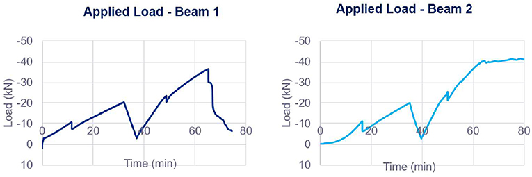
Figure 2. Load scheme applied to each beam specimen.
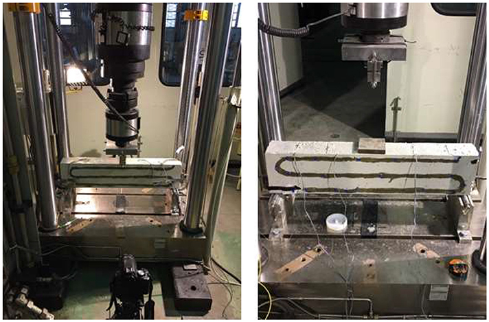
Figure 3. Tested reinforced concrete beam 1 (Left) and beam 2 (Right).
The DOFS performed very satisfactorily in all segments until the occurrence of cracking, Figures 4, 5. In Beam 1, DOFS detect and localize the crack formation for a load of 7.5 kN while it is not visually observable. The same occurs in Beam 2, where the expected tensile strength is surpassed for a load of 9.2 kN although this crack is not yet detected visually.
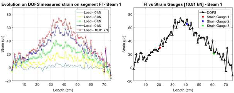
Figure 4. Strains measured by the DOFS on the embedded segment for Beam 1.
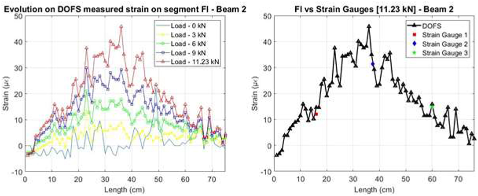
Figure 5. Strains measured by the DOFS on the embedded segment for Beam 2.
When comparing the DOFS segment attached to the rebar (FI) in each specimen, besides the good agreement with the strain gauges it is recognized a better performance of the measurements in Beam 1 (cyanoacrylate bonded) when compared to Beam 2 (epoxy bonded) especially for its initial unloaded stage reading. Moreover, for load levels where cracking had already occurred, as detected by the segments bonded externally to the concrete surface, damage is not yet noticed at the rebar level.
Nevertheless, in both beams, sometime after the occurrence of damage, at the crack location, the DOFS measurements start showcasing huge and alternative positive and negative peaks. In this way, it was proposed to perform a post-processing routine, where the un-reliable measurements were removed being identified by their inherent very low spectral shift quality (SSQ) (Luna Innovations Incorporated, 2013) followed by the surface interpolation of the remaining accurate values.
In a simple way, the SSQ is an indicator of the cross-correlation between the baseline measurement and measurement spectra normalized by the maximum expected value, being theoretically between 0 and 1, where 1 corresponds to a perfect correlation. The manufacturer recommends the consideration of any measurements with a SSQ below 0.15 as unreliable or inaccurate, since when this threshold is reached, it is likely that the strain or temperature change has exceeded the measurable range.
The low SSQ values are found to be close to the crack location in the segments adhered to the surface of the concrete and within a wider area in the rebar segment. This is due to the fact that segments with large strain gradients increase the noise levels of the DOFS measurements (Kreger et al., 2006).
Despite conducting the same post-processing routine for each beam DOFS data, it is observed that for Beam 2 still some peaks are present. This is thought to be related to the better performance of the cyanoacrylate adhesive when bonded to steel when compared with the use of the epoxy one.
Notwithstanding, both beams' data sets, after the removal of the un-reliable values, present a reasonable strain evolution which is compatible with the applied load. This is more noticeable for Beam 1 since, in this case, the sensor performed properly until a later stage of the loading process, further validating the conclusion of the cyanoacrylate as a better bonding adhesive for the implementation of polyimide-coated fibers attached to steel rebars.
After the conduction of this process, and when comparing the strain values after cracking with what was measured by the strain gauges and with what was visually observed directly on the beam specimens for the corresponding load level a good agreement is observed for both beams, Figure 6.
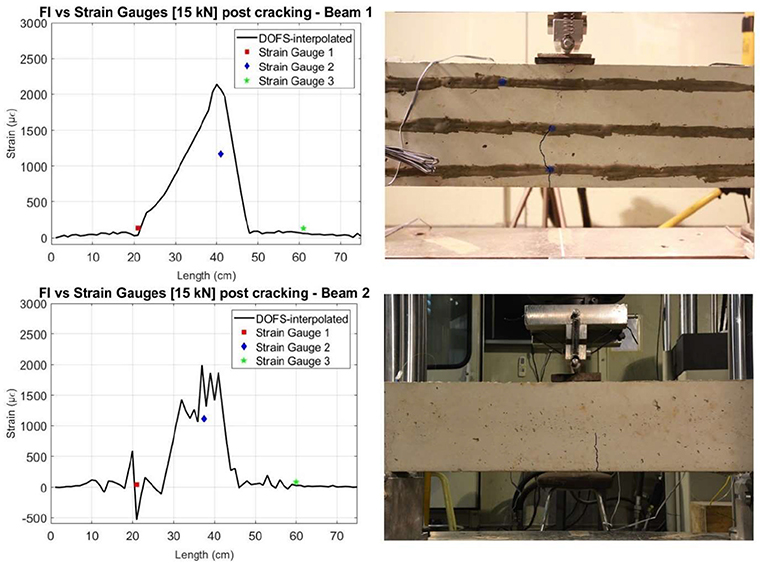
Figure 6. Comparison of interpolated values of DOFS with strain gauges at load level 15 kN (Left) and photo specimen with highlighted crack (Right) – Beam 1 (Top), Beam 2 (Bottom).
In this way, it is concluded that good results are obtained within the undamaged stage of the specimen and that the proposed installation method can effectively detect and locate the damage formation. For the following stage, a post-processing technique was proposed in order to eliminate the identified inaccurate peak values, which are originated after crack formation. This experimental campaign showed the feasibility of deploying a single polyimide coated Rayleigh OFDR based DOFS, simultaneously to the rebar and external surface of a reinforced concrete element. Notwithstanding, further repeat experiments are advisable in order to reinforce these conclusions.
DOFS Spatial Resolution and Adhesives Comparison Analysis
As mentioned before, in order to obtain the optimal strain transfer between the sensor and the monitored material, the topic of its deployment is of considerable importance. In addition to the removal of any grease or dust present in the surface of the host material and the smoothening of the surface, the decision on the adhesive to bond the optical fiber sensor to the surface has to be assessed.
To this end, a laboratory experiment was devised where another single 5.2 m polyimide DOFS was attached to the surface of a reinforced concrete beam using four different adhesives: epoxy, cyanoacrylate, polyester and neutral cure silicone and tested under a three-point load test. These adhesives were chosen based on previous experience of the research group and through what was found during a literature review on this topic. The DOFS were bonded to the concrete performing a pattern with four equal segments (each one bonded with aforementioned selected adhesives) on the bottom surface of the beam, Figure 7, with the objective of inducing the same strain levels, allowing the direct comparison between them. For comparison purposes, three strain gauges were also deployed–SG1, SG2, and SG3.
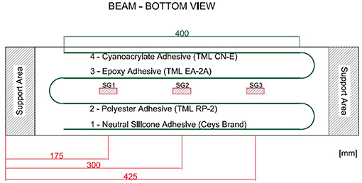
Figure 7. Scheme of the tested reinforced concrete beam and its instrumented sensors (DOFS and strain gauges).
Additionally, the influence of different spatial resolution inputs in the used DOFS system was assessed, as an increased detail provided by an enhanced spatial resolution would be of interest mainly for the case of sub-mm crack detection.
Spatial Resolution Comparison
To perform the analysis of the influence of different spatial resolutions, it was decided to conduct three separate but identical load cycles with different spatial resolution with a maximum applied load of 11 kN and therefore without inducing cracking. Three spatial resolutions were tested: 1 cm, 3 cm, and 1 mm, thus representing 520, 174, and 5,191 measuring points, respectively. The obtained results are depicted in Figure 8. Here, it is observed how the data collected with a 1 mm spatial resolution presents a significantly higher spatial variability when compared with the other two.
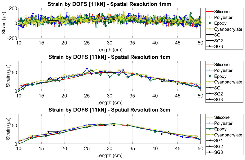
Figure 8. Strain data measured by DOFS with different spatial resolution inputs and adhesives.
When calculating the nominal difference between these sets the values presented in Table 1 were obtained.
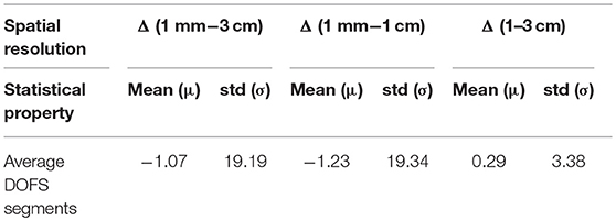
Table 1. Comparison of spatial resolution sets difference [All units represent microstrain (με)].
Although the differences of the mean (μ) were very close to zero, the calculated standard deviations (σ) were very different between the analyzed sets. Moreover, even after performing a moving average to the initially measured data collected with the 1 mm, relatively erratic measurements appeared, when compared with the other data sets. Therefore, the researchers concluded that no real advantages were accomplished by using a sub cm spatial resolution, being in this way decided to suggest the use of 1 cm spatial resolution when using this type of experimental setup.
Different Bonding Adhesives Comparison
Using the same load cycles as in the previous study of the spatial resolution influence, the performance of the different used bonding adhesives while not inducing cracking was also assessed. Here, it was verified that all bonded segments were able to follow the applied load correctly and presented a good agreement with the data from the strain gauges, Figure 9.
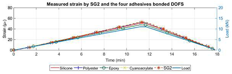
Figure 9. Comparison of strain measured by DOFS at SG2 location with inputted load at right axis.
In fact, at the beam mid-span, where higher strain levels are produced, the higher difference between DOFS bonded segments and the strain gauge at that location was of 5.54 με while all others are close or below 2 με, which corresponds to the strain resolution provided by the used DOFS interrogator system.
Additionally, when assessing the measured strain spatial variability achieved by each bonded segment throughout the applied load sequence, Figure 10, it was observed how the silicone bonded segment presented smoother and more homogenous readings. This is related with its inherently lower shear elasticity modulus, which allows for a fiber adjustment movement within the adhesive.
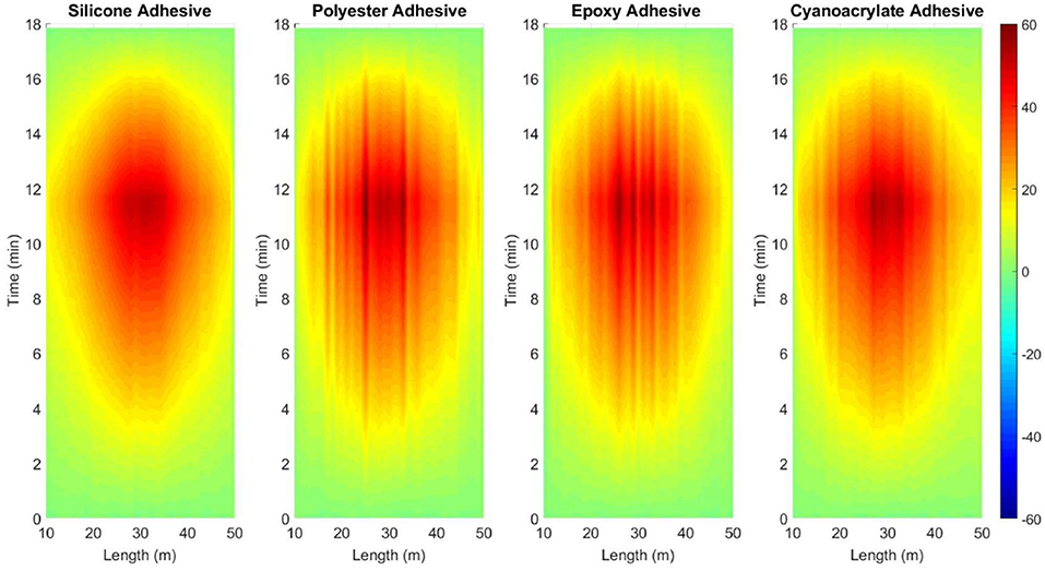
Figure 10. Measured strain by the four different bonded segments under elastic range.
When analyzing these adhesives for a load cycle where cracking was induced in the specimen and further loaded until rupture, it was verified that all four different bonded segments were able to effectively detect and locate the crack formation although with different performances. Whereas, the polyester, epoxy, and cyanoacrylate bonded segments presented strain peaks with narrow bases at the location of the crack (around 2 cm), the silicone bonded segment while also displaying a strain peak at the crack location, it had a wider base (around 20 cm). This issue makes the detection of further crack formation in this area impractical when using this particular bonding adhesive.
On the other hand, when continuing to assess the performance of each segment after the crack initiation, it was seen, how apart from the silicone bonded segment, all other adhesives presented alternating positive and negative strain peaks at the crack locations, where only positive increasing strains corresponding to applied tension should be observed.
As in the first and aforementioned experimental campaign, a post-processing routine was performed where unreliable values were removed (SSQ values below the acceptable threshold of 0.15), Figure 11.
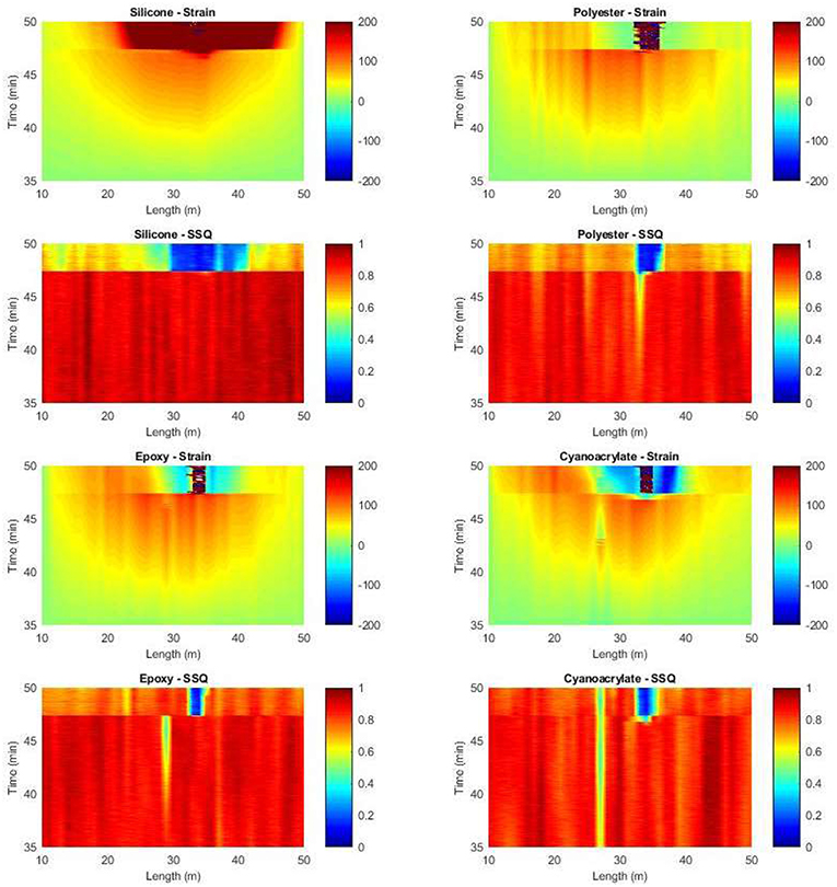
Figure 11. Measured strain and corresponding SSQ values for each bonded segment between minute 35 and 50.
Additionally, since negative values were still remaining after this action, which is not coherent to the expected tension being developed in the bottom surface of the concrete beam, these values were also removed. In the end, a surface interpolation was performed replacing, in this way, the removed and inaccurate data points.
With this operation, the silicone bonded segment presented the fewer identified inaccurate data points, leading therefore to fewer removed data from the original measurements. Nevertheless, still presenting a significantly wide area of influence for the developed crack, corresponding to almost 2/3 of the total length of the bonded segment. For the other segments, relatively more data was replaced, especially with respect to the removing of negative strain measurements.
In conclusion, it is seen how the neutral cure silicone can be a good option as a bonding adhesive for situations where the quantification of crack damage is not relevant or even where cracking is not foreseen as in prestressed concrete elements. Regarding the other adhesives, it is concluded that they can also be considered for the same situations as suggested for the silicone adhesive, although with a higher spatial variability and more susceptible to the differently sized aggregates in the concrete material. In this experiment, these adhesives present the aforementioned high peaks while also displaying negative strain measurements.
Long-Term Performance of DOFS
The experiment described here is not indeed to be a completely independent campaign from the one detailed in the previous section as it was conducted in the same time period and using a very similar beam and sensing setup. Here, the main objective was to assess the accuracy and reliability of DOFS measurements over time when monitoring structures over a long-term period when several load cycles are applied. To the authors' knowledge, very few publications were found regarding the performance of Rayleigh based OFDR DOFS under fatigue loading.
Moreover, in the few existing publications on this topic, all of these previous conducted studies were conducted within other engineering fields and mostly applied to composite elements, where the surface characteristics of the material highly affect the fatigue response when compared with concrete elements.
For this purpose, a laboratory experiment was devised where 2 million load cycles were induced on two reinforced concrete beams (FA1 and FA2), instrumented with Rayleigh based DOFS, in a similar way as depicted in Figure 7. The applied load cycles were defined in a way to replicate expected real world conditions for the case of a standard highway bridge.
Two different load stages were considered for the stress range of the load cycles. The lower value of the stress range corresponded to the actuation of the structures' self-weight and permanent loads, whereas the upper one corresponded to the addition of the traffic load. This was represented by a four-axle truck with a load of 120 kN by axle and multiplied by a dynamic factor of 1.3 as described in Fatigue Load Model 3 of EN 1991-2 (CEN, 2002).
Therefore, and in order to reproduce these stress levels in the tested beam specimens in the laboratory, the load cycles range was from 11.75 to 13.73 kN. The cycling load was applied with a frequency of 4 cycles per second with a sinusoidal profile until reaching 2 million cycles (500 ks) as illustrated in Figure 12. This inputted frequency was defined to stimulate as much as possible the real conditions in concrete bridges under traffic and also to facilitate the logistics of such experiment in terms of its duration.
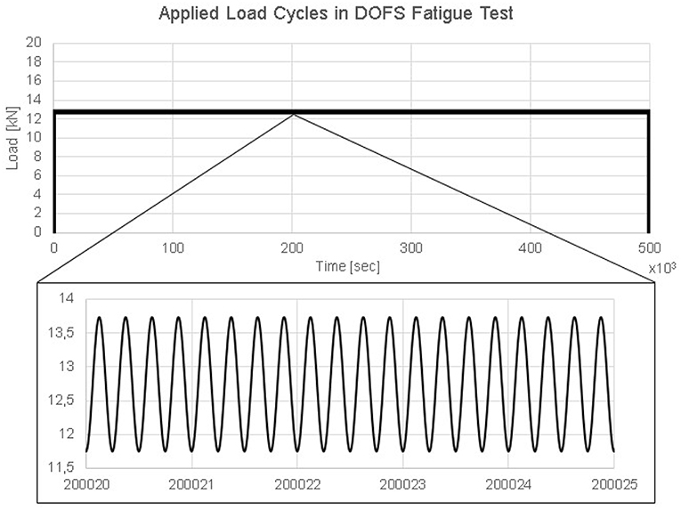
Figure 12. Defined load sequence for fatigue cycles.
The main difference between the test in each beam was that for beam FA1 the load was applied directly to the beam in an un-cracked condition, whereas for beam FA2, the beam was initially loaded statically until a 28 kN load (inducing in this way cracking), unloaded and then finally loaded with the same 2 million cycles as beam FA1. The goal being to assess the fatigue performance in both un-cracked and cracked concrete, simulating the cases where the DOFS will be bonded to prestressed (no cracking) or reinforced (cracking) concrete bridges.
The measured strain by the different segments of the DOFS at the beam midspan over the applied number of load cycles for beam FA1 is depicted in Figure 13. It is seen how the DOFS measurements follow the strain gauge with a good agreement along the number of cycles. In addition, it is important to point out that the applied load frequency was of 4 Hz while the sampling acquisition of the DOFS was of one measurement every 5 s while being of 1 Hz for the strain gauges. This partly explains the observed difference between both set of sensors as the magnitude of the applied strain range was of around 12 με.
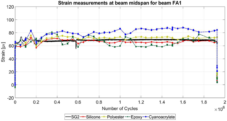
Figure 13. Measured strain at beam FA1 mid-span over the load cycles.
In the case of beam FA2, it was observed that the DOFS measurements presented a good agreement with the strain gauge at the same location (SG2) until cracking was initiated. After the cracking detection, all DOFS segments and strain gauges measurements followed with more or less agreement the applied load until the beginning of the 2 million load cycles application. Nonetheless, it was observed how after the post-cracking stage and unloading stage the strain measurements slightly diverged between the different DOFS segments and the strain gauges, especially in the case of the silicone bonded segment.
Nevertheless, when assessing the measured strain during the 2 million load cycles, it was again observed a reasonable good agreement with the data measured by the strain gauges as seen in Figure 14. The observed difference between both set of sensors was more relevant for the DOFS using silicone and polyester and almost negligible for epoxy and cyanoacrylate. Notwithstanding, these differences were, as in the case of beam FA1, related with the system strain resolution (±2 με), different sampling rates in the acquisition systems and strain range due to the amplitude of the load cycles (12 με).
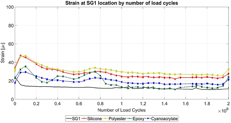
Figure 14. Measured strain at beam FA2 at SG1 location over the load cycles.
In conclusion, with this test it was possible to acquire encouraging results on the use of this novel technology for long-term monitoring periods with fatigue induced behavior. The distributed optical fiber technology displayed a good performance under fatigue loading for both the un-cracked and cracked scenarios by presenting similar results as the strain gauges' measurements. As a result, it is plausible to affirm that fatigue loading doesn't seem to affect the performance of DOFS when obtaining strain profiles along its length. Furthermore, all used bonding adhesives appear to perform well in these conditions with the observed different performances between the deployed adhesives to be almost negligible.
Real World Application
In this section it is presented the case where it was possible to monitor a real world structure through the use of distributed optical fiber sensing. This was an important opportunity to evaluate the feasibility of implementing these sensors in real scenarios, which present different challenges when compared with the case of laboratory experiments in controlled environments.
In these situations, besides the immediate challenge presented by the environmental agents that can harm and influence the sensors' measurements, a more difficult and defying scenario is present regarding the sensor deployment in the structure to be monitored. Due to the fragility of the fiber used in this research, special care has to be taken when handling the fiber, what in some construction sites can be challenging.
Sarajevo Bridge
The monitored structure was the Sarajevo Bridge located over one of the main roadway entrances of the city of Barcelona, Spain with a high traffic flow during peak hours, Figure 15. It is a two-span bridge with span lengths of 36 and 50 m and where each span is built up by three box-girder prestressed concrete beams connected by an upper reinforced concrete slab.
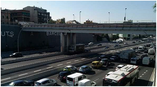
Figure 15. Sarajevo Bridge at Barcelona, Spain.
This structure was subjected to rehabilitation works to enlarge the existing deck while introducing new steel elements in order to increase pedestrian traffic and improve its aesthetics. Due to the high traffic volume in the bridge and the underneath lanes, it was not possible to close the bridge to traffic or place a temporary support beneath the rehabilitated structure. As a result, it was compulsory to perform the required rehabilitation works while maintaining the structure in its normal service operation and without the possibility of adding a temporary support. Adding the importance of this structure to the city's road network, it was paramount to perform a close monitoring follow up of the induced stresses during and after the execution of the works.
In this way, two 50 m length DOFS (DOFS 1 and DOFS 2) were placed in the internal bottom surface of the box-girder beam most susceptible to be subjected to a larger load increment in the 36 m length span, Figure 16. The fibers were bonded using an epoxy adhesive, adjusting to the length of the span while the remaining 14 m of the DOFS were left unbonded and later used for temperature compensation as explained in Barrias et al. (2018).
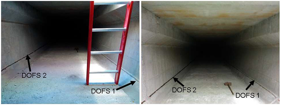
Figure 16. Instrumented DOFS in interior of box-girder beam at Sarajevo bridge.
The monitoring period in this application was between June of 2015 and February of 2016 (8 months) and in this way, the DOFS measurements were conducted in chosen days throughout this period, being that the maximum and minimum measured values in each of those dates was used to generate envelope response graphs.
One important aspect of this application was that due to the vast mentioned duration of the monitoring period, the influence of temperature on the readings had to be considered. Both the refractive index of the backscattered light and the materials which compose the DOFS are dependent on these temperature changes, so a correction of this thermal induced error on the monitoring output was required.
There is the possibility to use two different ways to perform this temperature compensation when using Rayleigh OFDR based DOFS (or OBR) as long as there are segments of the deployed fiber which aren't bonded to the structure and therefore only subjected to the thermal variation induced changes. These techniques are namely the point-to-point thermal compensation and thermal compensation by fiber loop. The first provides a more solid mitigation of the thermal effects, however if not any significant local temperature gradients are expected throughout the fiber cable, both can be used.
In the case of Sarajevo Bridge application, since 14 m of the fiber were left unbonded in the original spool case, it was therefore only possible to use the second mentioned technique. Here, in order to obtain the pure mechanical strain developed during the monitoring period, it was necessary to subtract from the total and original strain obtained in the bonded part of the fiber, both the effects of the refractive index dependent apparent strain and the coefficient of thermal expansion dependent apparent strain. In this way, an average of the spectral shift measured for the entire length of the unbonded segment is calculated and then subtracted to the calculated average of the measured data of the bonded segment.
As mentioned above, by using this thermal compensation by fiber loop, it is assumed that the ambient temperature variation is the same along the entire length of the monitored box-girder. This restricts the use of the DOFS data to a global structural behavior analysis. However, by dividing the entire deployed DOFS length in different smaller segments this analysis can be improved. Five different segments (corresponding to different span adjusting DOFS lengths) were proposed, where a thermal compensation is conducted for each one. In this way, the average and purely mechanical induced strain evolution for each section of the monitored span is obtained as depicted in Figure 17.
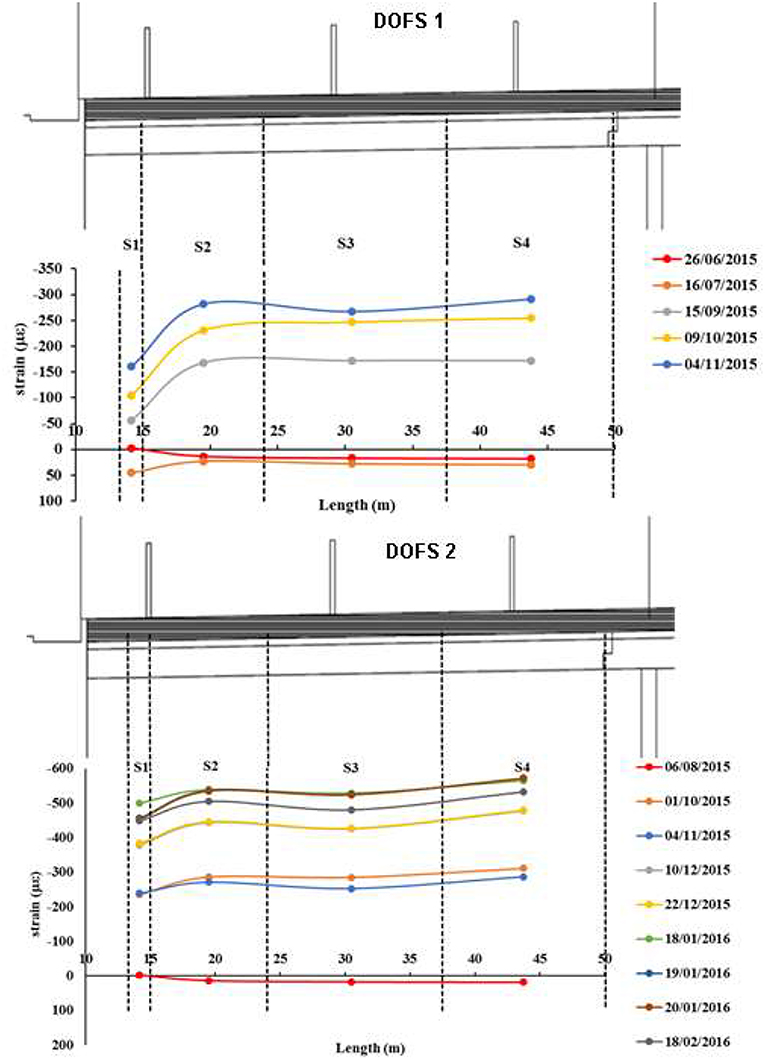
Figure 17. Mean mechanical distribution measured by DOFS 1 (Top) and DOFS 2 (Bottom).
It should be noted that segment S0 corresponds to the unbonded segment of the DOFS and is not plotted in the mentioned figures. Moreover, it was seen that apart from segment S1 which presents a relative lower mechanical strain than the other segments of the DOFS length due to its proximity to the bridge elastomeric bearing, the remaining ones present a uniform mechanical strain distribution. Therefore, it can be concluded that the main responsible for the verified strain variation is the decrease of temperature between summer and winter translated to a uniform shortage of the box-girder.
This procedure when using Rayleigh OFDR based DOFS in a real world structure verifies the validity of the use of this novel technology in real case scenario while showcasing these sensors unique advantageous capabilities and limitations. It is seen how these sensors are able to follow and monitor the structural behavior while only requiring the use of a relative small number of sensors and simple monitoring system.
This monitoring process was able to assess the structure's safety trough the development of the construction works in a continuous way (both in time and space). Furthermore, the real-time monitoring allowed for the structure to continue to work normally.
This application further demonstrated the potential and feasibility of use of OBR based DOFS technology in civil engineering SHM applications by providing valuable and reliable information on the structures condition for the bridge owner.
Conclusions
This research investigated the use of the promising novel technology of distributed optical fiber sensing (DOFS) in SHM applications of bridges and large-scale structures. Despite encouraging results, the use of this technology still presented some uncertainties, which limited its more widespread use. Therefore, different experiments and analysis were conducted in order to provide more relevant results and conclusions as guidelines for the future use in the SHM of concrete structures.
Initially, it was assessed a new deployment methodology of Rayleigh OFDR based DOFS both embedded and bonded to the external surface of reinforced concrete structures, both in un-cracked, and cracked conditions. DOFS performed very well within the elastic range and the measured data agreed almost perfectly with the one measured by the strain gauges. The proposed methodology allowed for the detection and localization of the developed crack and it was concluded that the use of cyanoacrylate adhesive for the bonding of the DOFS to the rebar element provided better results when compared with the use of epoxy.
Nevertheless, it was verified how after a certain load level following the formation and detection of cracking both at the surface and rebar levels, a significant change of stiffness in the elements seemed to give origin to unreliable data values at the location of the crack, being more noticeable in the DOFS segment adhered to the rebar. This was associated to the decrease of the spectral shift quality (SSQ) values at those point locations. Therefore, a post-processing method was proposed to overcome this issue and enabling the plausible assessment of the DOFS measured data after cracking. Therefore, with this experiment it was displayed the feasibility of deploying such implementation method of a DOFS system for the monitoring of a RC beam.
Moreover, while assessing different spatial resolution values, it was seen how, the use of a 1 mm spatial resolution did not enhance the measured results at all. Therefore, the spatial resolution of 1 cm was considered to be the most suitable and recommended for future applications in concrete elements using this system.
Additionally, when comparing the performance of the different deployed bonding adhesives (silicone, polyester, epoxy, and cyanoacrylate) it was seen how for un-cracked conditions, all segments agreed well with the data measured by the strain gauges although with a relative smoother and more uniform data measurement by the silicone bonded segment. In conclusion, where cracking is not expected, the use of any of this adhesives provides reliable results albeit a slightly better performance by the silicone adhesive.
For cracked condition scenarios, it was observed how the different bonded segments performed relatively differently under the same load stages. As a conclusion, the decision on the optimal bonding adhesive, in these cases, depends on the objectives and performance preferences. The use of silicone adhesive provides measurements which seem to be less influenced by the decrease of the associated spectral shift quality values and therefore provide coherent information for further stages of the load but presenting less accurate results. Other adhesives, especially the cyanoacrylate, provide more accurate spatially data but are limited earlier to the effect of the decrease of the SSQ values.
When assessing the long-term reliability and fatigue performance, the conclusions is that the DOFS measurements agreed reasonably well with the ones obtained by strain gauges for the entire duration of the test (2 million cycles). DOFS measurements presented a good stability along the number of cycles and no malfunction due to fatigue effects were observed.
Finally, regarding the application of this sensing system on a prestressed concrete bridge (Sarajevo bridge in Barcelona) during its widening and rehabilitation it was seen how this monitoring system, through the use of a minimal number of fiber sensors, allowed for the correct surveillance and following-up of the developed strain variations. Moreover, being this possible while allowing the monitored structure to continue in service during the conduction of the referred works. Lastly, the relatively long monitoring period proved that even the challenge presented by the important seasonal temperature variations on the sensor were able to be corrected and in this way not interfere in the correct assessment of the actual mechanical strains.
Moreover, in order to reinforce and strengthen the results obtained and discussed here, further laboratorial and real world campaigns are planned and in line. In particular, the performance of DOFS in the crack pattern and width assessment in concrete members in shear is under investigation and some relevant results are already available (Rodríguez, 2017)1,2.
Data Availability
The datasets generated for this study are available on request to the corresponding author.
Author Contributions
AB and JC conceived and designed the laboratory experiments. AB performed these experiments with the aid of SV in the implementation step of the DOFS to the specimens and the interrogator software configuration. SV designed and was the main responsible for the real world application. SV contributed with the OBR system for the conduction of all experiments. All authors analyzed the data from all experiments. AB and JC wrote the paper.
Conflict of Interest Statement
The authors declare that the research was conducted in the absence of any commercial or financial relationships that could be construed as a potential conflict of interest.
Acknowledgments
The authors want to acknowledge the financial support provided by the European Union's Horizon 2020 research and innovation programme under the Marie Sklodowska-Curie grant agreement No. 642453.
Footnotes
1. ^Rodríguez, G., Casas, J. R., and Villalba, S. (Submitted). Shear crack width assessment in concrete structures by 2D distributed optical fiber. Eng. Struct.
2. ^Rodríguez, G., Casas, J. R., and Villalba, S. (Submitted). Shear crack pattern identification in concrete elements via distributed optical fiber grid. Struct. Infrastruct. Eng.
References
Barrias, A., Casas, J. R., and Villalba, S. (2016). A review of distributed optical fiber sensors for civil engineering applications. Sensors 16:E748. doi: 10.3390/s16050748
Barrias, A., Rodriguez, G., Casas, J. R., and Villalba, S. (2018). Application of distributed optical fiber sensors for the health monitoring of two real structures in Barcelona. Struct. Infrastruct. Eng. 14, 967–985. doi: 10.1080/15732479.2018.1438479
Casas, J. R., and Cruz, P. J. S. (2003). Fiber optic sensors for bridge monitoring. J. Bridge Eng. 8, 362–373. doi: 10.1061/(ASCE)1084-0702(2003)8:6(362)
Ferdinand, P. (2014). “The evolution of optical fiber sensors technologies during the 35 last years and their applications in structure health monitoring,” in EWSHM-7th European Workshop on Structural Health Monitoring (Nantes).
Glisic, B., Hubbell, D., Sigurdardottir, D. H., and Yao, Y. (2013). Damage detection and characterization using long-gauge and distributed fiber optic sensors. Opt. Eng. 52:87101. doi: 10.1117/1.OE.52.8.087101
Glisic, B., and Inaudi, D. (2012). Development of method for in-service crack detection based on distributed fiber optic sensors. Struct. Health Monit. 11, 161–171. doi: 10.1177/1475921711414233
Glišić, B., Posenato, D., and Inaudi, D. (2007). “Integrity monitoring of old steel bridge using fiber optic distributed sensors based on brillouin scattering,” in The 14th International Symposium on: Smart Structures and Materials & Nondestructive Evaluation and Health Monitoring, 65310P. San Diego, CA: International Society for Optics and Photonics.
Grave, J. H. L., Håheim, M. L., and Echtermeyer, A. T. (2015). Measuring changing strain fields in composites with distributed fiber-optic sensing using the optical backscatter reflectometer. Composites Part B 74, 138–146. doi: 10.1016/j.compositesb.2015.01.003
Kreger, S. T., Gifford, D. K., Froggatt, M. E., Soller, B. J., and Wolfe, M. S. (2006). “High resolution distributed strain or temperature measurements in single-and multi-mode fiber using swept-wavelength interferometry,” in Optical Fiber Sensors, ThE42 (Cancun: Optical Society of America), 23–27. doi: 10.1364/OFS.2006.ThE42
Ravet, F., Briffod, F., Glisić, B., Nikles, M., and Inaudi, D. (2009). Submillimeter crack detection with brillouin-based fiber-optic sensors. IEEE Sensors J. 9, 1391–1396. doi: 10.1109/JSEN.2009.2019325
Keywords: structural health monitoring, bridges, distributed optical fiber sensors, reinforced concrete, Rayleigh backscattering
Citation: Barrias A, Casas JR and Villalba S (2019) SHM of Reinforced Concrete Elements by Rayleigh Backscattering DOFS. Front. Built Environ. 5:30. doi: 10.3389/fbuil.2019.00030
Received: 01 December 2018; Accepted: 20 February 2019;
Published: 14 March 2019.
Edited by:
Branko Glisic, Princeton University, United StatesReviewed by:
Dryver R. Huston, University of Vermont, United StatesGiacomo Navarra, Kore University of Enna, Italy
Copyright © 2019 Barrias, Casas and Villalba. This is an open-access article distributed under the terms of the Creative Commons Attribution License (CC BY). The use, distribution or reproduction in other forums is permitted, provided the original author(s) and the copyright owner(s) are credited and that the original publication in this journal is cited, in accordance with accepted academic practice. No use, distribution or reproduction is permitted which does not comply with these terms.
*Correspondence: António Barrias, YW50b25pby5qb3NlLmRlLnNvdXNhQHVwYy5lZHU=; orcid.org/0000-0002-2298-7956
†Joan R. Casas, orcid.org/0000-0003-4473-4308