 Georgios K. Tairidis
 Aliki D. Muradova
 Georgios E. Stavroulakis
- School of Production Engineering and Management, Computational Mechanics and Optimization Institute, Technical University of Crete, Chania, Greece
In the present investigation, the principles of dynamic morphing of smart truss structures and mechanisms are discussed. A possible way in order to find the optimal geometry of the structure for the enhancement of structural performance in terms of vibration control is sought. The vibrations of the host dynamic structures are monitored by controllers which are based on the principles of Mamdani-type fuzzy inference and Sugeno-type adaptive neuro-fuzzy inference. More specifically, the objective of the present study is a design, tuning, and an application of robust intelligent control mechanisms by means of the suppression of structural vibrations for several types of excitation forces. The proposed models are discretized by using a finite element method. For the time integration of the equations of motion, the Newmark-β method is used. The calculations and the analysis are conducted within the Matlab environment by using the Adaptive Neuro-Fuzzy Inference System (ANFIS) tool, which is included in the fuzzy toolbox. The controllers are tested with different excitation forces applied on a truss-shaped structure. The control outputs are applied on each time of the simulation in order to achieve the lowest possible deformation and to prevent potential damage or corruption of the structure. The same principles are used for the dynamic morphing of structures and mechanisms. The proposed formulation can be applied, among many others, on smart irrigation systems such as spray booms, on radio-telescope bases, on the spars of smart wings, on aircraft wings etc.
Introduction
In real-life applications, oscillations and possible damage of structures are caused due to several excitation forces. In this direction, a design engineer should put effort on the development of an optimal control system which minimizes the probability of damage occurrence and therefore the financial cost. Mathematical classical control methods usually provide satisfactory results in case of linear laws under certain conditions, while non-linear controllers based on fuzzy and neuro-fuzzy logic techniques are applicable to non-linear problems.
Smart structures incorporate some control strategies in order to reduce disturbances. There are several techniques intended for suppression vibrations. A review of active structural control is done by Korkmaz (2011). In the paper of Fisco and Adeli (2011) hybrid control strategies, active and semi-active vibration suppressions are discussed. The active control with using the continuous elements for a two-cell planar truss is done by Kevorkian and Pascal (2003). The paper of Preumont et al. (1992) summarizes a research in the field of active damping of space structures including trusses. The truss structure is provided with two active elements that can be placed in various locations. In the work of Lin and Zheng (2012) a neuro-fuzzy system is applied for an optimal design of structures and online fuzzy control is described by Xu et al. (2016).
In the present paper, in order to suppress vibrations of a two-dimensional truss structure two different control approaches are proposed. The first one is based on fuzzy logic approach and another one is based on neuro-fuzzy inference. The same ideas can be realized in dynamic morphing problems. Some approaches, other than fuzzy, have been also elaborated for the control of disturbances in radio-telescopes [see among others (Jiménez-Garcia et al., 2000; Su et al., 2003)]. The application of fuzzy techniques allows quick and effective control of the oscillations of structures. A general survey on industrial applications of fuzzy control in different fields of engineering is given in the work of Precup and Hellendoorn (2011). Adaptive control schemes with fuzzy logic are described by Zeinoun and Khorrami (1994).
The term morphing is used in order to describe a broad range of components which adapt to planned and unplanned requirements of structures such as smart wings of aircrafts. This adaptation usually includes the change of shape in real-time, e.g., during in-flight operation [see among others (Paradies and Ciresa, 2009; Weisshaar, 2013)]. The morphing of aerospace vehicles and structures is discussed in the book of Valasek (2012). Smart materials such as shape memory alloys (SMA), piezoelectric actuators (PZT), and shape memory polymers (SMP) are used in this direction (Sofla et al., 2010). A morphing wing considering both shape memory alloys (SMAs) and macro-fiber composites (MFCs) on the trailing edge is presented in the work of Scheller et al. (2016). Feedback is also used for dynamic morphing of piezocomposite actuated structures, such as flexible wings as described in the recent work of Wang et al. (2018).
For the present investigation, a dynamic mechanical model, based on finite elements, is constructed. The Newmark method is employed for the numerical integration of the obtained system of equations, which are known from dynamics as the equation of motion. The fuzzy controller is developed based on a Mamdani-type fuzzy inference system, and the neuro-fuzzy controller is based on a Sugeno-fuzzy inference system. The learning process is performed within the ANFIS tool of Matlab, using training data from the host structure. The input data are the displacement and the velocity of a suitably selected node of the structure, while the output is the control force which needs to be applied on the structure. The computational schemes using fuzzy inference systems of Mamdani-type have been proposed before for smart beams by Tairidis et al. (2009) and for plates by Muradova and Stavroulakis (2013, 2015), respectively. Adaptive neuro-fuzzy control has been used for suppression of vibrations of smart structures like beams and plates by Stavroulakis et al. (2011) and Muradova et al. (2017). Some other optimization techniques for the enhancement of the characteristics of fuzzy control, include, among others, genetic algorithms and particle swarm optimization as have been described in the works of Tairidis et al. (2016) and Marinaki et al. (2010), respectively.
The smart truss, which is studied in the present work, has specific geometrical characteristics and it can simulate the base of a radio-telescope and its behavior in cross-section consideration. The proposed control schemes, after being parameterized, are tested on the structural model for different excitations in order to examine the reaction of the structure. Moreover, to achieve the lowest possible deformation of the structure, the control is applied on each step of numerical integration. The presented techniques can be easily extended on the real three-dimensional radio telescope base or in other applications, such as the spray booms irrigation systems, the spars of wind turbine blades, the smart wings of aircrafts, etc.
In the present investigation, both fuzzy and neuro-fuzzy controls are used in the direction of dynamic morphing of the smart structure. The results of both methods are compared with each other in order to prove the efficiency of the proposed control method.
The paper is organized as follows. In section Mechanical Model of a Two-Dimensional Truss Structure, the mechanical model, which is based on finite element approximations is analytically described. A numerical integration scheme for this model is constructed in section Numerical Integration. Sections Fuzzy Control Scheme and Neuro-Fuzzy Control Scheme focus on a design of fuzzy and neuro-fuzzy control, respectively. In section Numerical Simulation Algorithm, a numerical simulation algorithm is developed. Numerical examples, namely, a comparison between the numerical results obtained by means of fuzzy and neuro-fuzzy control systems are presented in section Numerical Results. In section Conclusions, the main conclusions are discussed.
Mechanical Model Of a Two-Dimensional Truss Structure
In this section, a two-dimensional truss dynamic model is derived based on the finite element method. The truss model is considered to have similar behavior in vibrations with a cross section of radio telescope base. It is supposed that the mechanical model of the truss consists of a finite number of parts (bars), connected with each other. Each bar of the structure corresponds to one element. The elements are in turn connected with each other by nodes. The truss, considered in the present study, consists of 17 nodes and forms 31 rods (elements). It is fixed (supported) in two nodes as shown in Figure 1.
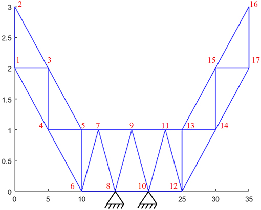
Figure 1. The truss structure with dimensions in meters, numbering of nodes, and two supports at nodes 8 and 10.
Let the truss consists of Ne rods, elements. A displacement for every bar element of the truss on the bar axis is described by a linear function,
where û1x and û2x, are the nodal displacements of two nodes at the end of each bar element, , and l is the length of the bar element. According to the classical theory for the deformation, stress and displacement the following relations hold:
where ε is the deformation (strain) tensor, σ is the stress tensor and E is the Young modulus (modulus of elasticity). Hence for the tension we have,
where A is the area of cross section of a bar.
Furthermore, for the nodal forces we have
According to the Newton's second law of motion for each node we have the nodal external (applied) force , which is equal to the sum of the internal force and nodal mass times acceleration. Thus, for each element on and ŷ axes we have
or in the vector form
where [m] is the mass diagonal matrix, i.e., [m] = diag(m1, m1, m2, m2).
Distributed mass of the bar elements can be neglected or considered as a lumped mass on the nodes of the elements. For the internal forces from (1) and (2) it follows
where , and is the stiffness matrix of the bar element, defined as
Substituting (4) into (3) and taking into account the damping effects we obtain a system of equations for the bar element
where [c] is the damping matrix.
Now we need to introduce a transformation matrix for the bar element. According to the rules for the nodal displacements we have
where [Tr] is the transformation matrix,
where c = cosθ, s = sinθ, and θ is the angle between x and axes.
Analogously, for the nodal internal forces,
Using the previous results (4), (6), and (7) it follows
Hence
where the global stiffness matrix [k] is defined as
The formula (6) is also holds for the velocity and the acceleration . Thus, since
from (5) we obtain for each element
A global stiffness, mass and damping matrices for the whole truss (the structure, composed of more than one element) are obtained by assembling the matrices for each element of the structure. Thus, the global stiffness, mass and damping matrices and external force are written as
where Ne is the number of elements. Further, k(e), m(e), c(e) and are the global stiffness, mass and damping matrices and the external force, respectively, for each bar element, defined before as k, m, c and fex, respectively. Thus, for all the elements, the equation of motion (8) reads in the following vector form,
Numerical Integration
The system of equations (9) can be solved by numerical integration (the Runge-Kutta method, finite differences, etc.). Here, the second order direct numerical integration Newmark-β method is applied. This method is flexible, because it does not require the smoothness of the second derivative. The following formulas for the nodal displacement, velocity and acceleration hold
where
and N is the number of nodes. Substituting the expressions for uk and into (9) and adding control forces, i.e., function Zk+1, to the right-hand side we obtain
where
For the initial values of the nodal displacements, velocity, and acceleration we have , , .
For the integration constants we take β = 0, 25, γ = 0, 5 that corresponds to the case of unconditionally stable constant average acceleration method.
Fuzzy Control Scheme
A non-linear fuzzy controller is developed using the Fuzzy Toolbox of Matlab. More specifically, a Mamdani fuzzy inference with two inputs, that is the displacement and the velocity, and one output, that is the control force, is considered. For the mapping of the fuzzy variables, both triangular, as well as trapezoidal membership functions are used as shown in Figures 2–4.
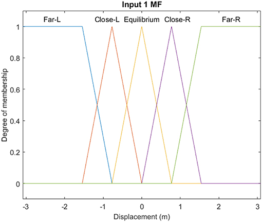
Figure 2. Membership functions of input 1 (displacement) of the fuzzy controller.
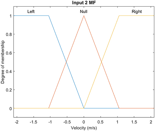
Figure 3. Membership functions of input 2 (velocity) of the fuzzy controller.
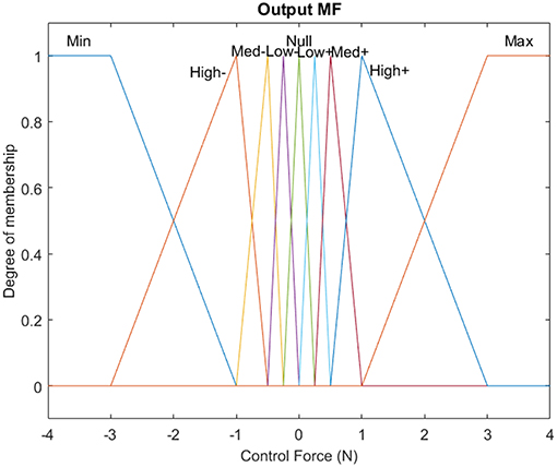
Figure 4. Membership functions of the output of the fuzzy controller.
The control system takes the inputs and makes the decisions based on a set of predefined verbal rules, which are known as fuzzy rules (Tairidis et al., 2009; Muradova and Stavroulakis, 2013). For the description of the controller, fifteen verbal rules have been considered, according to the classic pendulum problem. The weights of the rules were all set equal to unity “1.” For the combination of the fuzzy rules the AND logical operator is used. The implication method has been set to minimum (min), while the aggregation method has been set to maximum (max). The defuzzified crisp value of output has been created by using the MOM (Mean of Maximum) defuzzification method. The set of these rules is shown in Table 1, while a graphic representation of the rules is depicted on the fuzzy surface (see Figure 5).
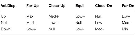
Table 1. Fuzzy inference system rules.
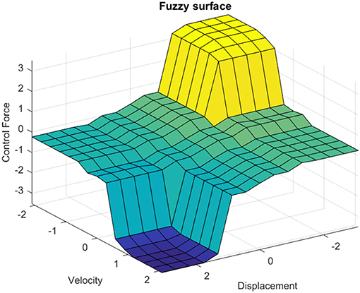
Figure 5. Fuzzy surface of the Mamdani-type fuzzy controller.
Neuro-Fuzzy control Scheme
The design of the non-linear neuro-fuzzy controller is based on classical fuzzy inference systems in combination with artificial neural networks. The resulted system, i.e., an adaptive neuro-fuzzy inference system (ANFIS) can provide very good results in terms of vibration suppression of smart structures, even when the examined system is partially known.
Neuro-fuzzy control works with Sugeno-type fuzzy inference systems and can be optimized using the ANFIS procedure. The whole process consists of a few steps. On the first step of the procedure, discrete values of the displacement and velocity without control are computed. These values are used as data for training in the ANFIS. A Sugeno-type controller is built and optimized in ANFIS, by using the training data obtained in the previous step. The output of this controller is a control force which can be used at each time step of the simulation for vibration suppression. Subtractive clustering is used for the creation of the membership functions, which are called clusters and the initial fuzzy inference systems is generated. After the creation of the initial system, the controller is trained, that is, optimized by using a hybrid method, which is based on the least square and the backpropagation method. Finally, the system optimizes, i.e., corrects/adapts, the rules and all the characteristics of the Sugeno controller. The details of the procedure can be found in the article of Muradova et al. (2017).
The controller which is developed for the present investigation, is trained using input data from node 11, while the external force which is applied on the structure is of sinusoidal form. The membership functions, which occurred by the training process in the form of clusters, are seven in number for each input, i.e., for the displacement and the velocity and are depicted in Figure 6. Neuro-fuzzy controllers are of Sugeno-type, which means that there are not any membership functions for the output. Linear functions or constant values are used instead. In the present case, seven constant values are created for the outputs by the training procedure. After the learning process, the ANFIS algorithm provided 7 rules for the decision-making system, which are shown verbally in Table 2 and schematically, in the form of a fuzzy surface, in Figure 7, respectively.
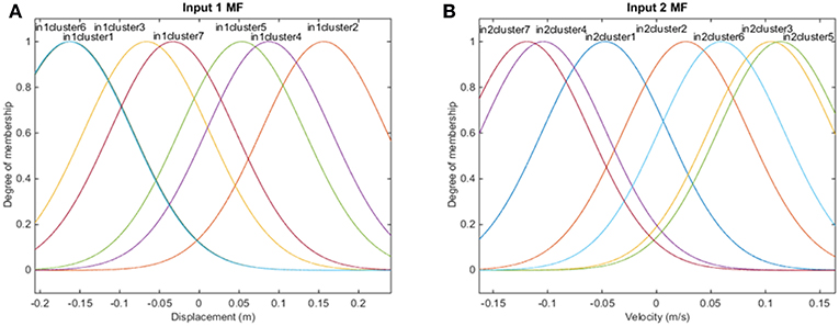
Figure 6. Membership functions of (A) input 1 (displacement) and (B) input 2 (velocity) of the neuro-fuzzy controller.
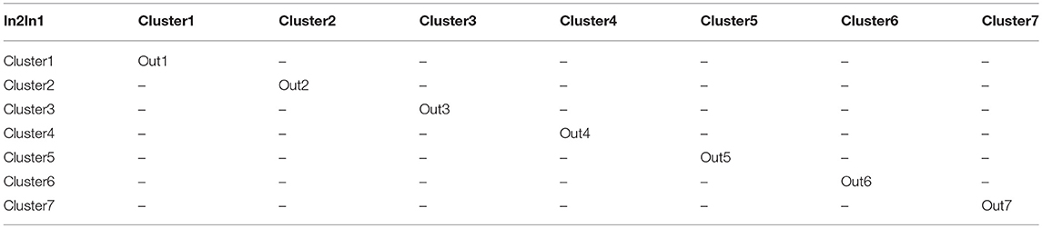
Table 2. Neuro-fuzzy inference system rules.

Figure 7. Fuzzy surface of the Sugeno-type neuro-fuzzy controller.
Numerical Simulation Algorithm
In this section the numerical simulation algorithm, based on the methodology described in sections Mechanical Model of a Two-Dimensional Truss Structure, Numerical Integration, Fuzzy Control Scheme, and Neuro-Fuzzy Control Scheme is presented. Namely, the dynamic behavior of the mechanical finite element model is approximated by the numerical integration Newmark-β method. Then, with the use of the fuzzy and neuro-fuzzy logic dynamic control of the shape of the truss is performed. The steps of the algorithm are given below.
Step 1. Design a truss, i.e., set up the coordinates of the nodes and the connectivity of elements (bars) in the truss.
Step 2. Set up material constants, a number of loads and boundary conditions for the truss.
Step 3. Compute the stiffness global matrix K according to the design of the truss and the boundary conditions.
Step 4. Compute the total loading forces F and compose the damping matrix C and the mass matrix M.
Step 5. Set up the number of time steps KT and the final time T.
Step 6. Compute the displacementuk+1 and the velocity by the Newmark-β formulas (10) for the equation of motion (9) without control function.
Step 7. Calculate the maximum and minimum of the displacement and velocity. These data can also be obtained from practical estimations, and they are used for suitable scaling of fuzzy control.
Step 8. Compose the Mamdani/Sugeno type FIS, based on the computed values of the displacement and the velocity, and the fuzzy logic rules for morphing. In case of the application of the neuro-fuzzy with Sugeno-type controller, the data are trained in ANFIS. Then the generated FIS is optimized using the hybrid method (the least square and backpropagation).
Step 9. Put the initial time, t = t0 and k = 0.
Step 10. Compute the control Zk+1 using the generated FIS and the values uk and .
Step 11. Compute the displacement uk+1and velocity by the Newmark-β formulas (10) for the equation of motion (9) with control function Zk+ 1.
Step 12. Repeat Steps 10–11 for k = 1, 2, …, KT−1, i.e., continue to perform dynamic morphing (e.g., till the desired shape of the truss is reached).
Numerical Results
In the present investigation, the implementation of the above described techniques has been done on the two-dimensional truss model, as described in section Mechanical Model of a Two-Dimensional Truss Structure. The structure is shown with dimensions in Figure 1. Regarding the excitation, the truss is subjected to a vertical loading at node 16, while the control is applied through the neighboring element which is formed by nodes 16 and 17 (see Figure 1).
As for the excitations, a constant force which equals to F1 = −4N and a sinusoidal one which equals to F2 = −4sin(10πt)N have been considered for the numerical examples.
For reasons of demonstration, the results of fuzzy and neuro-fuzzy control are presented side by side. Namely, a comparison between the results of fuzzy and neuro-fuzzy control for the constant external loading are presented in Figures 8–10, while the results for the harmonic loading are given in Figures 11–13.
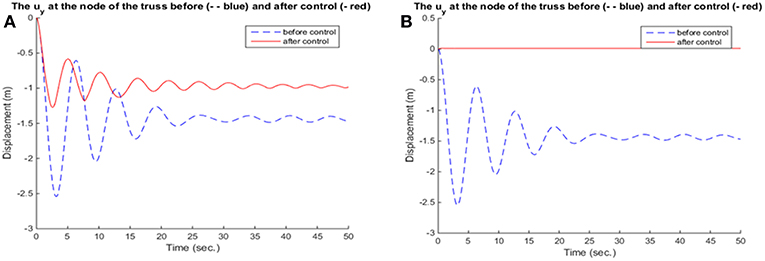
Figure 8. Displacement of node 16 for (A) fuzzy controller and (B) neuro-fuzzy controller.
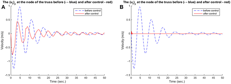
Figure 9. Velocity of node 16 for (A) fuzzy controller and (B) neuro-fuzzy controller.
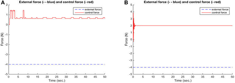
Figure 10. Diagram of forces for (A) fuzzy controller and (B) neuro-fuzzy controller.
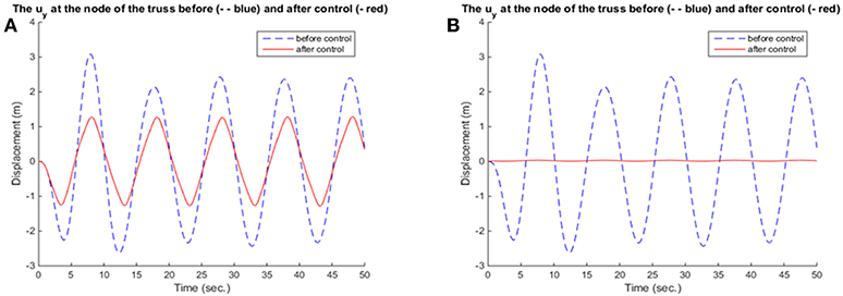
Figure 11. Displacement of node 16 for (A) fuzzy controller and (B) neuro-fuzzy controller.
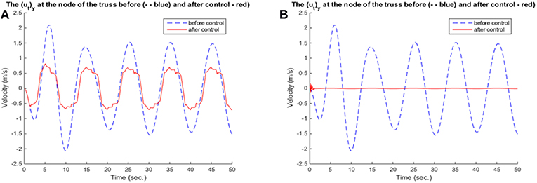
Figure 12. Velocity of node 16 for (A) fuzzy controller and (B) neuro-fuzzy controller.
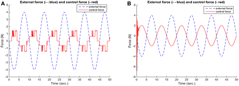
Figure 13. Diagram of forces for (A) fuzzy controller and (B) neuro-fuzzy controller.
Neuro-fuzzy control provides better and more smooth results, in terms of the reduction of displacement, as seen in Figures 8, 11 and velocity and in Figures 9, 12, respectively. Figures 10, 13 show that in the beginning of the simulation the control forces, required in the neuro-fuzzy are more than in the fuzzy applications. However, from the time t > 2 approximately the applied control forces are less in neuro-fuzzy than in the fuzzy performances. Thus, the adaptive controller, not only significantly deteriorates the vibrations of the truss structure, but also accomplishes that goal within <1 s. So, for the present investigation, one can conclude that between fuzzy and neuro-fuzzy control, the latter is clearly more effective and smoother as well. However, fuzzy control is stable in some more general cases.
Conclusions
The suppression of vibrations, in the direction of dynamic morphing of a two-dimensional smart truss-structure, which can simulate a behavior of a radio-telescope base, has been considered in the present investigation. The finite element method has been used in a conjunction with controllers based on the principles of fuzzy logic. Both traditional fuzzy and adaptive neuro-fuzzy schemes have been chosen.
The controllers have been applied close to the loading positions, in the sense of collocated control. From the numerical examples, it is shown that the neuro-fuzzy controller provides the best results in terms of vibration suppression of both displacement and velocity of the examined node of the structure. The effectiveness of this controller is probably due to the larger number of clusters which have been created by the neuro-fuzzy system, compared to the other two neuro-fuzzy schemes. Another reason could be the selection of the node from which the input data have been received.
Regarding fuzzy control, although it does not correspond to an optimal control problem, an important point is that this type of control is based on verbal rules, which are easily applicable to a wide range of problems. Its effectiveness depends on the selection of these rules which are usually chosen empirically. In some cases, as shown herein, the results can be improved by using an adaptive neural-fuzzy inference system. In other cases, the results can be improved by using global optimization tools, such as genetic algorithms or particle swarm optimization.
From the numerical results, one can also observe that neuro-fuzzy control is quite effective, especially if trained properly. In the present paper, the training has been carried out using training data, that is information about the displacement, the velocity, and the force, at the nodes close to the ones where external loading was applied. Another important notice was that neuro-fuzzy control, compared to the traditional fuzzy controller, was more efficient and managed to deteriorate the vibrations significantly and also fast, within a short time-frame which was necessary for the adjustment of the control mechanism. From the comparison of the results obtained by fuzzy and neuro-fuzzy control in this work, one can conclude that in some cases the ANFIS can be much preferable for reducing vibrations in structures, although, the FIS is more stable and applicable for a wide class of problems.
The proposed here methodology provides the designer-engineer with the necessary feedback in order to improve the design and the strength of structures. Thus, it can be applied, not only on radio telescopes bases, but also on other problems of industrial and structural engineering, such as morphing of smart structures and mechanisms.
Data Availability
The datasets generated for this study are available on request to the corresponding author.
Author Contributions
All authors listed have made a substantial, direct and intellectual contribution to the work, and approved it for publication.
Conflict of Interest Statement
The authors declare that the research was conducted in the absence of any commercial or financial relationships that could be construed as a potential conflict of interest.
References
Fisco, N. R., and Adeli, H. (2011). Smart structures: part II: hybrid control systems and control strategies. Sci. Iran. 18, 285–295. doi: 10.1016/j.scient.2011.05.035
Jiménez-Garcia, S., Magaña, M. E., Benitez-Read, J. S., and Martinez-Carballido, J. (2000). Modelling, simulation, and gain scheduling control of large radiotelescopes. Simul. Pract. Theory 8, 141–160. doi: 10.1016/S0928-4869(00)00013-6
Kevorkian, S., and Pascal, M. (2003). Distributed control of truss structures. J. Vib. Control 9, 7–23. doi: 10.1177/1077546303009001740
Korkmaz, S. (2011). A review of active structural control: challenges for engineering informatics. Comput. Struct. 89, 2113–2132. doi: 10.1016/j.compstruc.2011.07.010
Lin, J., and Zheng, Y. B. (2012). Vibration suppression control of smart piezoelectric rotating truss structure by parallel neuro-fuzzy control with genetic algorithm tuning. J. Sound Vib. 331, 3677–3694. doi: 10.1016/j.jsv.2012.04.001
Marinaki, M., Marinakis, Y., and Stavroulakis, G. E. (2010). Fuzzy control optimized by PSO for vibration suppression of beams. Control Eng. Pract. 18, 618–629. doi: 10.1016/j.conengprac.2010.03.001
Muradova, A. D., and Stavroulakis, G. E. (2013). Fuzzy vibration control of a smart plate. Int. J. Comput. Methods Eng. Sci. Mech. 14, 212–220. doi: 10.1080/15502287.2012.711427
Muradova, A. D., and Stavroulakis, G. E. (2015). Hybrid control of vibrations of smart von Kármán. Acta Mech. 226, 3463–3475. doi: 10.1007/s00707-015-1387-2
Muradova, A. D., Tairidis, G. K., and Stavroulakis, G. E. (2017). Adaptive neuro fuzzy vibration control of a smart plate. Numeric. Algebra Control Optim. 7, 251–271. doi: 10.3934/naco.2017017
Paradies, R., and Ciresa, P. (2009). Active wing design with integrated flight control using piezoelectric macro fiber composites. Smart Mater. Struct. 18:035010. doi: 10.1088/0964-1726/18/3/035010
Precup, R. E., and Hellendoorn, H. (2011). A survey on industrial applications of fuzzy control. Comp. Industry 62, 213–226. doi: 10.1016/j.compind.2010.10.001
Preumont, A., Dufour, J. P., and Malekian, C. (1992). Active damping by a local force feedback with piezoelectric actuators. J. Guid. Control Dyn. 15, 390–395.
Scheller, J., Jodin, G., Rizzo, K. J., Duhayon, E., Rouchon, J.-F., Triantafyllou, M. S., et al. (2016). A combined smart-materials approach for next-generation airfoils. Solid State Phenomena 251, 106–112. doi: 10.4028/www.scientific.net/SSP.251.106
Sofla, A. Y. N., Meguid, S. A., Tan, K. T., and Yeo, W. K. (2010). Shape morphing of aircraft wing: status challenges. Mater. Des. 31, 1284–1292 doi: 10.1016/j.matdes.2009.09.011
Stavroulakis, G. E., Papachristou, I., Salonikidis, S., Papalaios, I., and Tairidis, G. K. (2011). “Neurofuzzy control for smart structures,” in Soft Computing Methods for Civil and Structural Engineering, eds Y. Tsompanakis and B. Topping (Stirlingshire: Saxe-Coburg Publications), 149–172.
Su, Y. X., Duan, B. Y., Wei, Q., Nan, R. D., and Peng, B. (2003). The wind-induced vibration control of feed supporting system for large spherical radio telescope using electrorheological damper. Mechatronics 13, 95–110. doi: 10.1016/S0957-4158(01)00042-3
Tairidis, G., Foutsitzi, G., Koutsianitis, P., and Stavroulakis, G. E. (2016). Fine tuning of a fuzzy controller for vibration suppression of smart plates using genetic algorithms. Adv. Eng. Softw. 101, 123–135. doi: 10.1016/j.advengsoft.2016.01.019
Tairidis, G. K., Stavroulakis, G. E., Marinova, D. G., and Zacharenakis, E. C. (2009). “Classical and soft robust active control of smart beams,” in Computational Structural Dynamics and Earthquake Engineering: Structures and Infrastructures 2, eds M. Papadrakakis, D. C. Charmpis, N. D. Lagaros, and Y. Tsompanakis (London: CRC Press, Balkema and Taylor and Francis Group), 165–178.
Wang, X., Zhou, W., and Wu, Z. (2018). Feedback tracking control for dynamic morphing of piezocomposite actuated flexible wings. J. Sound Vib. 416, 17–28. doi: 10.1016/j.jsv.2017.11.025
Weisshaar, T. A. (2013). Morphing aircraft systems: historical perspectives and future challenges. J. Aircraft 50, 337–353. doi: 10.2514/1.C031456
Xu, R., Li, D., and Jiang, J. (2016). Online learning fuzzy vibration control of smart truss structure. Proceedings of the Institution of Mechanical Engineers, Part G. J. Aerospace Eng. 231, 548–557. doi: 10.1177/0954410016640823
Keywords: truss structures, computational model, numerical simulation algorithm, fuzzy control, neuro-fuzzy control, dynamic morphing
Citation: Tairidis GK, Muradova AD and Stavroulakis GE (2019) Dynamic Morphing of Smart Trusses and Mechanisms Using Fuzzy and Neuro-Fuzzy Techniques. Front. Built Environ. 5:32. doi: 10.3389/fbuil.2019.00032
Received: 16 January 2019; Accepted: 27 February 2019;
Published: 20 March 2019.
Edited by:
Snehashish Chakraverty, National Institute of Technology, Rourkela, IndiaReviewed by:
Sukanta Nayak, Amrita Vishwa Vidyapeetham, IndiaEhsan Noroozinejad Farsangi, Graduate University of Advanced Technology, Iran
Copyright © 2019 Tairidis, Muradova and Stavroulakis. This is an open-access article distributed under the terms of the Creative Commons Attribution License (CC BY). The use, distribution or reproduction in other forums is permitted, provided the original author(s) and the copyright owner(s) are credited and that the original publication in this journal is cited, in accordance with accepted academic practice. No use, distribution or reproduction is permitted which does not comply with these terms.
*Correspondence: Aliki D. Muradova, YWxpa2lAbXJlZC50dWMuZ3I=