Abstract
One of the major applications of Fiber Reinforced Polymers (FRPs) in construction is in the confinement of reinforced concrete (RC) columns. The performance of FRP-confined concrete in circular columns has been extensively investigated in literature and the efficiency of the available models is nowadays considered to be satisfactory. However, the case of confinement of rectangular RC sections with FRPs is a more complex problem, the mechanism of which has not yet been adequately described. The aim of this work is to simplify the problem by proposing an iterative procedure based on the results of a three-dimensional finite element (3D FEM) analysis. An interesting finding is that the arching effect is not observed: indeed, the unconfined regions are partially confined and contribute a certain amount to the overall strength of the rectangular RC sections. Based on (a) a system of “generalized” springs, (b) well-known stress-strain laws, and (c) a failure criterion, a simplified mechanical model which gives the stress-strain behavior of a rectangular RC section confined by FRPs under concentric load is proposed. The algorithm takes into account all parameters available to designers, such as corner rounding radius, stiffness of the FRP, and concrete strength, while it can be easily understood and implemented. Its results are found to correlate adequately to recent experimental data yielded by large-scale tests on FRP-confined rectangular RC columns. Finally, in order to further evaluate the performance of this material model, it was implemented in the simulation of a series of experimental tests of FRP-retrofitted square RC columns under cyclic lateral loading simulating earthquake loads and simultaneous constant axial compression. In particular, all specimens were simulated using non-linear fiber elements, in which the FRP-confined concrete was modeled using the aforementioned material model. Comparison between the numerical and experimental hysteresis of the column is indicative of the effectiveness of the implemented modeling.
Introduction
The existing literature has an abundance of research works on modeling of circular reinforced concrete columns confined with FRP wraps. The compressive behavior of concrete cylinders externally confined with FRP under axial loads has been extensively studied nowadays. Numerous stress-strain models have been established during the last three decades. Some of these studies (Vintzileou and Panagiotidou, 2008; Jiang and Wu, 2012; Rousakis et al., 2012; Ozbakkaloglu et al., 2013, 2016; Rousakis and Tourtouras, 2015; Hany et al., 2016; Farahmandpour et al., 2017) concentrated on modeling the conditions during failure of FRP-confined concrete, including the ultimate compressive strength and the corresponding ultimate axial strain. Other studies simulate and describe the overall behavior of the stress-strain curve (Hosotani et al., 1997; Samaan et al., 1998; Spoelstra and Monti, 1999; Lam and Teng, 2003b; Yu et al., 2010a,b; Wang et al., 2011; Ozbakkaloglu and Lim, 2013; Eid and Paultre, 2017; Fahmy et al., 2017; Ismail et al., 2017). The available stress-strain models in literature have been grouped into two categories by Lam and Teng (2003a): (a) design-oriented models and (b) analysis-oriented models. Analysis-oriented models provide the stress-strain behavior using closed-form equations, while design-oriented models achieve that by an incremental numerical procedure. Such an analysis-oriented model for FRP-confined circular RC columns can be found in Megalooikonomou et al. (2012) and Papavasileiou and Megalooikonomou (2015). The advantage of design-oriented models over analysis-oriented models is their simplicity in application. Hence, they can be easily integrated to a structural analysis software, where they will yield results fast. To the authors' knowledge, such an analysis-oriented model for rectangular FRP-confined columns is not yet available. The proposed model was developed with the intention to be integrated in existing structural software. Furthermore, the approach of this model is unique. While other available models intend to capture the stress-strain behavior of FRP-confined concrete, the proposed model intends to simulate effectively the axial and lateral strain and, consequently, simulate the stress-strain behavior. The confining stress occurs as a reaction to the developed strain. This way, in addition to simulating the stress-strain behavior, the proposed model also yields the lateral dilation, which is not explicitly calculated in available models.
Literature on the modeling of rectangular FRP-confined RC columns is more limited. While existing studies (Karabinis and Kiousis, 1996; Teng et al., 2002; Lam and Teng, 2003a; Teng and Lam, 2004; Roussakis et al., 2008; Piscesa et al., 2018) have verified that FRP confinement can substantially enhance both the compressive strength, ductility, and energy dissipation of confined concrete in circular RC columns, the same method has been found to be much less effective for rectangular RC columns (Mirmiran et al., 1998; Rochette and Labossiere, 2000; Lam and Teng, 2003a; Megalooikonomou, 2007; Karabinis et al., 2008; De Luca et al., 2011). Corner rounding is overall recommended to enhance the confinement effectiveness in a rectangular RC column and to reduce the detrimental effect of sharp corners on the performance of FRP jackets which causes their rupture in relatively low strain (Lam and Teng, 2003a).
The main difference between the two RC column section cases is that in circular sections the confinement is uniform, while the same does not apply on rectangular sections (Mander et al., 1988). In the later, concrete is non-uniformly confined, so the effectiveness of the confinement is substantially reduced.
As illustrated in Figure 1, the imposed axial load on a circular section causes radial dilation (i.e., uniform strain) on the confining elements so the pressure applied by the jacket to the concrete as a reaction to its dilation is uniform as well. Hence, the stress-state developed in a circular section is uniform. In rectangular sections the confining element develops a concentration of stresses at the corners, where it develops its full capacity. Along the sides, its confining effectiveness is reduced as it does not have enough stiffness to fully restrain the dilation of the concrete column. Thus, a non-uniform confining stress-state is developed in the concrete section.
Figure 1
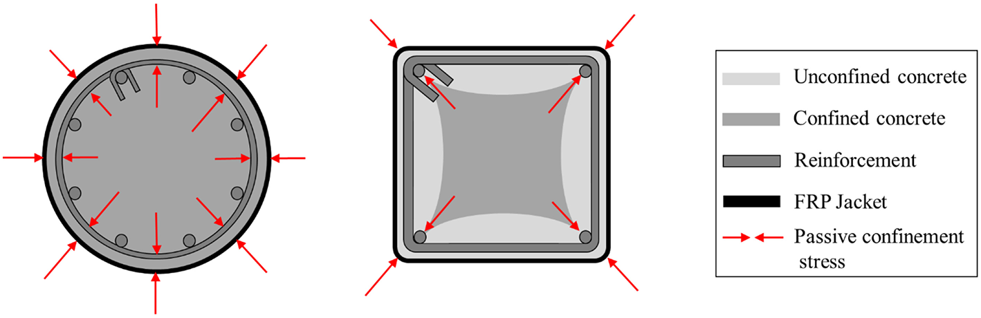
Confining mechanisms for circular and rectangular sections.
Previous modeling approaches concentrated mainly on dividing the rectangular section in a confined and an unconfined area (Figure 1), based on the concept of possible arching effect (e.g. Figure A1 in EN1998-3{A.4.4.2}). Then, the confined area is considered to be in a state of uniform biaxial confinement, as in the circular cross sections, thus allowing the use of formulas defined for circular FRP-confined elements. The unconfined part is considered to be unaffected.
Considering all the above remarks, an iterative procedure is being proposed in this research study based on the results of a 3D FEM analysis performed by the authors which indicates that the arching effect does not apply. The unconfined areas shown in Figure 1 are indeed partially confined and they contribute to the overall capacity of the section until they reach their maximum strength which is significantly reduced compared to that of the confined areas. In this work, a simplified analytical procedure to model the stress-strain behavior of a rectangular concrete section under concentric load is proposed which employs a system of “generalized” springs, well-known stress-strain laws and a failure criterion.
Numerical Analysis (Finite Element Model)
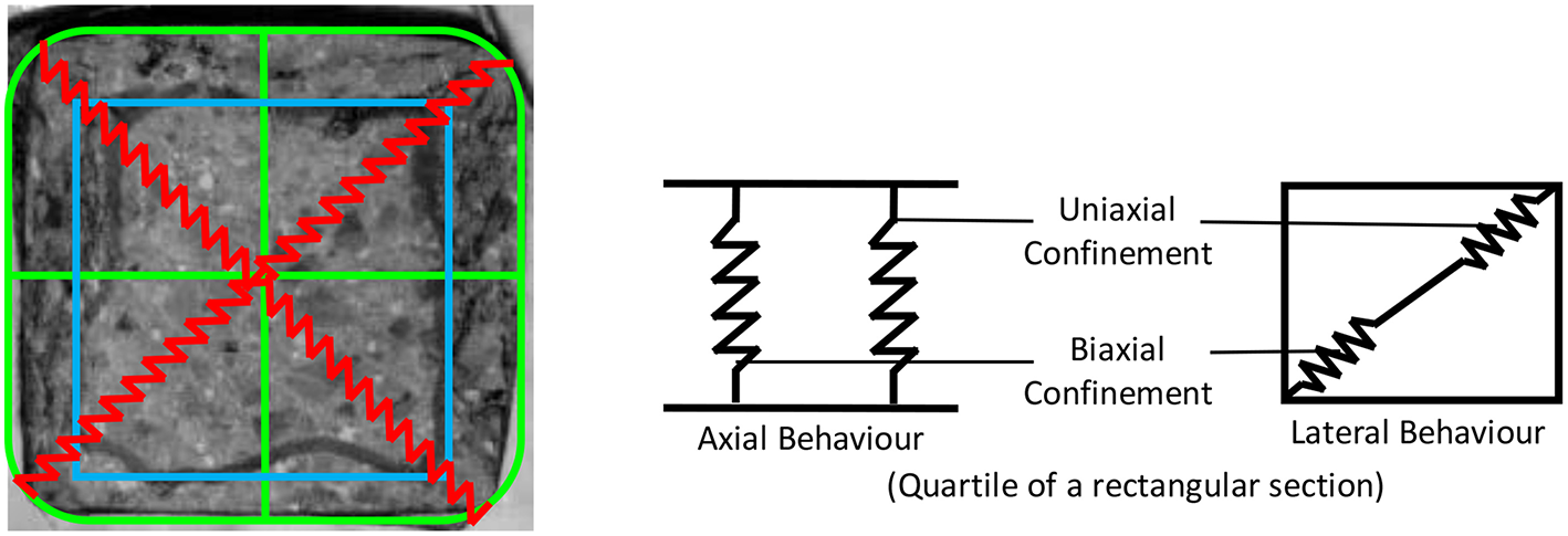
Figure 2 (Campione and Miraglia, 2003) shows the cross-section of an experimentally tested FRP-confined square concrete specimen under concentric load and the final concrete state along with the effective concrete core after FRP failure at the corner at the end of the experiment. Uneven damage can be observed throughout the section. Two different regions can be identified having different confining stress states. To determine the confining stresses and define the confined and unconfined regions in a rectangular section, a 3D Finite Element Model was developed in SAP 2000 (Computers Structures Inc., 2016). The model consists of a square concrete section 200 × 200 mm (Figure 2) with rounded corners. Solid elements are used to model concrete in the section. The FRP wrap is modeled using shell elements applied on the solid elements in the perimeter. A typical slice with thickness 10 mm was simulated. The CFRP wrap was modeled using an orthotropic material model with Young's modulus 3.61 105 MPa. The confined concrete was modeled with a “concrete” material with fck = 17 MPa. The applied axial displacement on the FEM model was increased until the lateral strain at the slice was equal to the maximum lateral strain at a cylindrical specimen, when it reaches the maximum strength. The maximum axial displacement was defined so that the lateral strain developed in the slice is equal to that an unconfined cylindrical specimen at the ultimate stress. The FEM results were plotted in three-dimensional graphs (Figure 3) to allow further study of the stress field. Verification of the results yielded by the FEM model against experimental results is available in Teng et al. (2015).
Figure 2
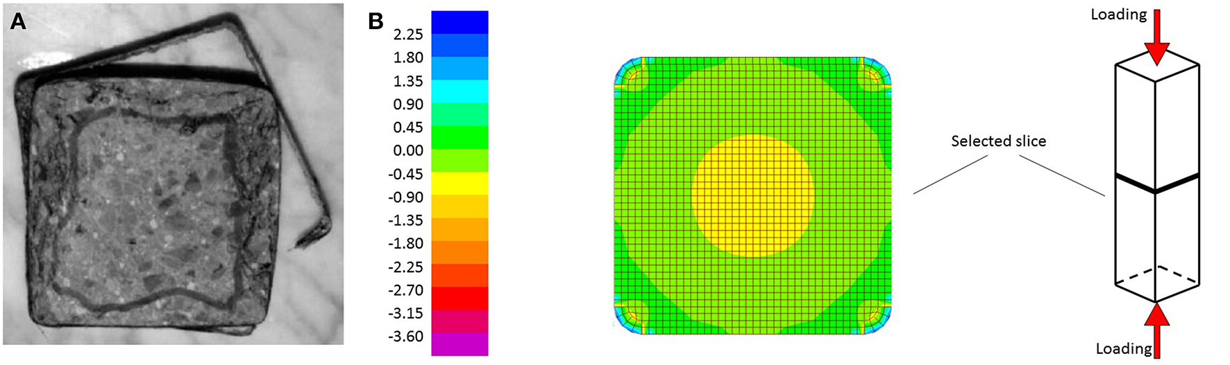
Cross-section of a short square column: (A) experiment (Campione and Miraglia, 2003), (B) FEM model.
Figure 3
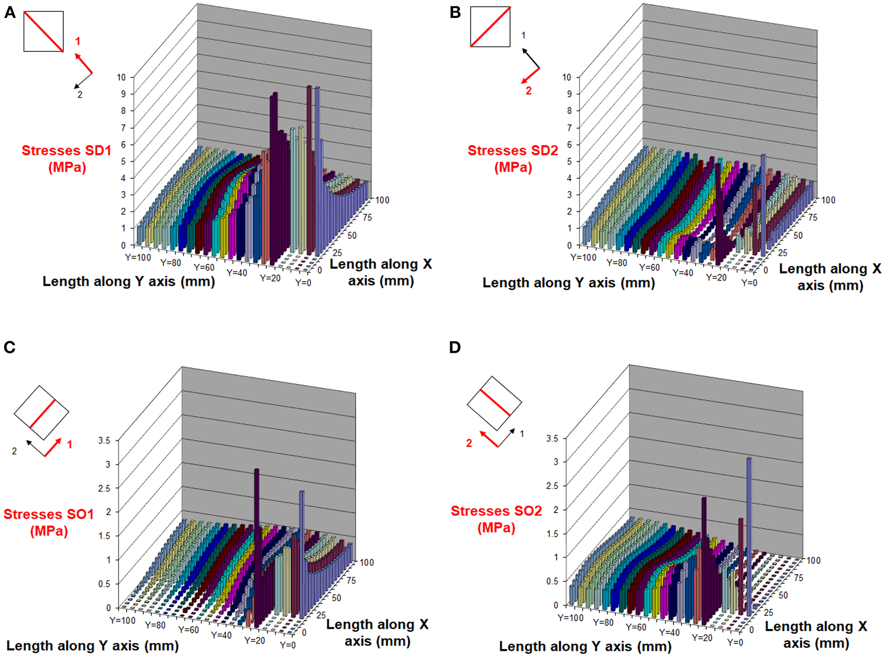
Confining stresses in a quartile of a square section 200 × 200 mm: along diagonal (A,B) and orthogonal (C,D) direction. The round corner stresses are not included.
Graphs in Figure 3 depict various stress fields in a quadrant of this square section. Stresses near the rounded corner are not shown since they represent local stress state. In Figures 3A,B, the normal stresses parallel to the diagonals (SD1 and SD2) are presented, while in Figures 3C,D normal stresses parallel to the section's sides (SO1 and SO2) are shown. Stresses parallel to the diagonal of the rounded corner, are increased near the corner, but moving inwards to the center of the section they reduce significantly (Megalooikonomou, 2007; Nisticò and Monti, 2014). Figure 3 also illustrates that the stresses perpendicular to the rounder corner diagonal direction and close to the sides have much lower values compared to those parallel to rounded corner diagonal, while toward the center they both become almost equal. This confirms that close to the center the confinement stress state is similar to circular sections. It is apparent from the plots of the stress field parallel to the orthogonal directions (Figures 3C,D) that some confining stresses are present along the side, while in the central part of the perpendicular side they are close to zero, as the confining device has minimal flexural stiffness.
Based on the aforementioned, the following main remarks can be made:
-
No unconfined concrete regions are observed, as assumed in many models. The parts near the edges are confined due to forces coming from the corners and moving parallel to the edges.
-
The confining forces near the perimeter have strong directionality (uniaxial confinement). On the contrary, near the center the state seems to be more uniform (biaxial confinement).
Accepting some tolerance, the regions where a biaxial and a uniaxial confinement exist can thoroughly be defined based on the ratio of the principal stresses of the two perpendicular directions in the joints of the FEM. Regarding the stress output in SAP 2000 (Computers Structures Inc., 2016), it should be noted that the direction of the middle principal stress (Smid) is perpendicular to the maximum (Smax) and minimum (Smin) principal directions.
For a specific tolerance (i.e., the ratio of the confining stresses is < 15%), the width of the biaxial stress state region is independent of the stiffness of the FRP (Figure 4). The radius of the rounded corner affects more the diagonal dimension of this region, while parallel to the sides the width remains the same (Figure 4). Unlike reinforced concrete, where the spacing of stirrups allows for such regions to develop, not only on the concrete cover but also between two consecutive stirrups, FRP-confined members are totally inside the FRP wrap. Due to the FRP's non-infinite stiffness, the FRP wrap can deform laterally to the cross-section. A finite slice of the FRP wrap performs as a cantilever beam with its ends at the rounded corners of the concrete section. The larger the deformation might get (i.e., a weaker FRP slice), the smaller the stress applied by the FRP on the confined concrete core is. No matter how small it might get, there is always stress applied on the concrete, so it does not perform as unconfined-concrete. The model considers the confinement pressure to be the same around the column. Hence, the smaller the side which this pressure distributes on, the more effective the confinement provided. This leads to the conclusion that, unlike unconfined concrete, in FRP-confined concrete the part of the section that is under biaxial confinement is not proportional to the relevant side, but proportional to the opposite side. This assumption is confirmed in previous works (Karam and Tabbara, 2005; Megalooikonomou, 2007). Based on these remarks, the width of the uniaxially confined region can be calculated using Equation (1), where a and b are the width and the depth of a rectangular section accordingly (Figure 8A). The dimensions of the regions are then directly related and determined according to this width (Figure 10).
Figure 4
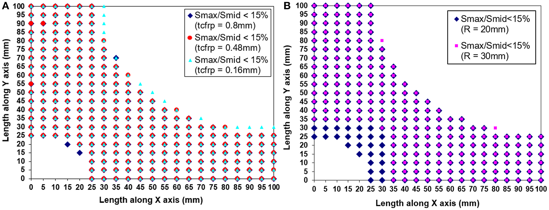
Uniaxially and biaxially confined regions: (A) different thicknesses of FRP jacket, (B) different radii of rounded corner.
The equations used in the proposed model was initially developed based on results yielded by modeling square FRP-confined concrete columns. Having assessed its effectiveness in modeling square columns, its applicability on rectangular columns was also assessed against experimental results and found to be adequate for a simplified analytical model.
Simplified Mechanical Model
A simplified mechanical model which describes the stress-strain behavior of a rectangular concrete cross-section under concentric load is proposed in this Section. A series of “generalized” springs (Figure 5) is used to describe the confinement mechanism. Compressed concrete expands laterally according to its confinement state. Such expansion activates the confining elements. The confining forces are applied to the section corners and transferred along the diagonal. In the proposed model, the contribution of the stirrups, as it is considered to be minimal and is not taken into account. This refers to cases that the stirrup spacing is adequately large to minimize the confinement effect due to stirrups.
Figure 5
FRP-confined rectangular concrete section modeling using “generalized” springs.
Figure 5 shows the springs used to model the axial and the lateral behavior of the section. Axially, the springs receive the same displacements and their cumulative strength is the summation of the strength of the individual springs (parallel system). Laterally, the springs receive the same force and their displacements are added (series system).
The “generalized” springs illustrated in Figure 5 use the constitutive law for concrete proposed by Pantazopoulou and Mills (1995). The model which relates the volumetric strain to the axial strain is shown in Figure 6 (right). In the same figure (left), the corresponding axial stress vs. axial strain is also demonstrated. It is evident that adequate confinement increases the ductility of the RC member which develops considerably larger strain until its stiffness and strength are particularly reduced leading to loss of stability. This is shown in the relationship between volumetric strain εv and axial strain εc illustrated in Figure 6.
Figure 6

Constitutive law for confined concrete (Pantazopoulou and Mills, 1995): (A) stress - strain relationship, (B) volumetric strain - axial strain relationship.
The initial slope of the curve (Equation 2, for ) is characteristic of a perfectly elastic condition. Both curves (for confined and unconfined concrete) deviate from this idealized situation. However, confined concrete develops large volumetric strain in much larger axial strain than unconfined concrete. Experimentally, in conditions of high confining stress, it has been observed that the εV vs. εc curve might even remain at negative values of εV throughout the test.
Prior to evident surface cracking, the εV–εc relationship is practically linear, with the lateral strain εl being equal to v·εc (v is typically within the range of 0.15–0.25). Beyond the limit axial strain (εc = εc,lim) that corresponds to lateral strain εl in excess of the tensile cracking of concrete εcr, the relationship between εV and εc shows substantial deviation from the idealized linear response and appears to be well approximated by a parabolic expression. For confined concrete under uniaxial load, the model is:
The product of αε · εco is the compressive axial strain at zero volumetric strain. For standard concrete strength, it is typically observed at axial strain from 2 to 3.5%0, i.e., at 80–100% the strain at peak stress εco. Coefficient bε denotes the degree of passive confinement of the concrete. For unconfined concrete loaded uniaxially, bε receives a value of 1, while smaller values are used as passive confining pressure increases. Coefficients αε and cε increase for higher strength concrete. Higher values of αε are used for higher nominal strength, up to 1, whereas the post peak response becomes more brittle (cε tends toward or exceeds 3). The same behavior (linear and parabolic part) has also been observed in the relationship between volumetric strain and axial stress (Figure 7).
Figure 7

Volumetric strain vs. axial stresses (Chaallal et al., 2000).
To comply with the mechanical model of the “generalized” springs and the regions with varying confinement, this model has been modified to correlate volumetric strain εV to axial stress σc according to Equation (3) (axial stress in MPa). Initially, change of volume occurs due to compaction and is practically linear up to the point of critical stress ασ·fco (unconfined concrete strength, usually ασ is taken as 0.7). For this axial stress level the Poisson's ratio ν remains within the range of 0.15–0.25 (here, the initial Young's modulus of concrete is determined as well). At this point, volume change is reversed resulting in volumetric expansion called (near-strength or at-peak-strength) dilatancy. A point can be defined where the compression rate of the specimen equates the expansion rate, thus resulting in zero volumetric strain. This point is considered to appear when the ultimate strength of the uniaxially confined region is reached (biaxial stress state, bσ = 1.2) (Kupfer et al., 1969). After the deterioration of this region, the expansion rate increases faster than the compression rate (second order parabola, cσ = 2) due to reduced effective confinement. The expansion becomes unstable during the crushing phase beyond the ultimate strength.
Based on Figure 8A, from the volumetric strain εV, both area strain (εA) and side strains (εaand εb) can be calculated as shown in Equations (3–7) (compressive axial strains are taken as negative).
Figure 8

(A) Deformed shape of a rectangular section based only on the diagonal lateral deformation, (B) Diagonal force applied to the lateral springs from the corner.
Based on the commonly applied assumption that no friction is developing between the FRP jacket and the concrete surface, the elongation strain of the sides can be assumed equal to the jacket strain. Therefore, the diagonal force of the jacket applied laterally from the corners to the springs in series can be determined by projection (Figure 8B):
The coefficient ke is a confinement efficiency factor by Karam and Tabbara (2005) which takes into account the increasing confinement effectiveness as the corner radius increases and is reduced when the ratio of the larger side to the smaller side of the cross section is increased. Figure 9 shows the considerations made for the definition of this factor.
Figure 9
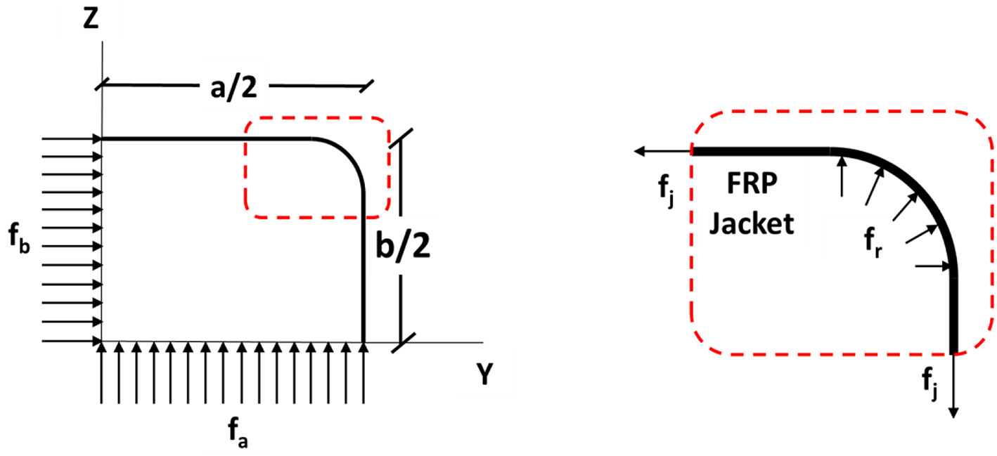
Mechanical behavior for determining the confinement effectiveness factor (Karam and Tabbara, 2005).
In Figure 9 (left), a confining FRP wrap is shown acting on a generic rectangular section with long side a, a short side b and radius of the rounded corner R. The concrete is assumed to be subjected to average (uniform) confining stresses at its middle sections with fa acting along the long side and fb acting along the short side as illustrated in Figure 9. The relationship between the fa, fb and the jacket tensile stress fj is determined statically (t is the thickness of the FRP wrap).
In Figure 9 (right), the FRP wrap is considered to act as a cable around the corner similarly to a pulley. Assuming no friction between the FRP jacket and the concrete surface, the relationship between fj and the confining stress at the corner fr is also defined statically:
Combining Equations (9) and (10), the following Equation can be defined:
Hence, the sharper the corner radius is, the higher the confining stress at the corner with respect to the average confining stress inside the cross section. This is supported by finite element analysis results presented by Parvin and Wang (2001) and experimental findings by Parvin and Wang (2002), and Chaallal et al. (2003).
Based to the aforementioned, the ratio of the average confinement stress over the maximum confinement stress attained in the cross section can be defined as the geometric confinement effectiveness factor (ke). In a rectangular section, the maximum confinement stress (fr) develops at the corners where stress concentration occurs on the jacket due to dilation of concrete. The average confinement stress is the average of the individual stresses fa and fb which act at the center of the section. The confinement effectiveness factor (ke) can be calculated as:
In a circular cross section, this factor is equal to 1, while for a square cross section, it is: ke = 2R/a. For an elongated rectangular cross section with semi-circular ends b ≫ a and 2R = a, the factor ke tends asymptotically to 0.5, which corresponds to confinement in a single direction in the cross-sectional plane.
After the determination of the diagonal force applied to the lateral springs in series from the corners, the lateral pressures for each region can also be calculated (Figure 10).
Figure 10
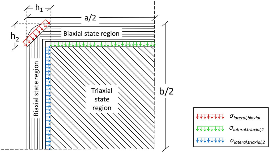
Confining pressures in the different regions.
The springs are in series so they develop the same force. For the biaxial stress state region, the force starts from the corners and moves parallel to the sides. Therefore, the confining pressure (assumed uniform) can be determined by the following equation:
The stress-strain model proposed by Popovics (1973) modified by Mander et al. (1988) is used to describe the behavior of the triaxial stress state region. Based on the lateral pressures calculated according to the Figure 10 the corresponding axial stress can be determined by the use of a stress-strain model corresponding to the confinement stress state of this region. The equation of the model by Mander et al. (1988) for the maximum axial stress σcc is not used in this case due to the fact that it describes the performance of uniform biaxial confining pressure. For the region in triaxial stress state, the uniform confining pressures on the sides of the section can be determined based on the geometry of the region (Figure 11) as follows:
Figure 11
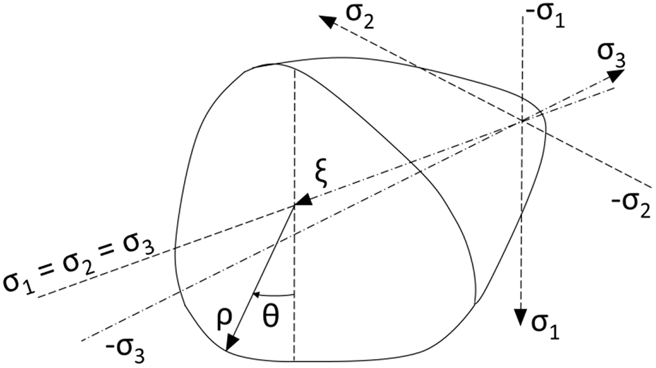
Ultimate strength surface by Ottosen (1977).
To comply with the above modeling of the triaxial stress-state region where the confining pressures are different in the two lateral directions (only in the case of a square section they are the same), a failure criterion where all the lateral confining stress state cases are considered is applied. Specifically, the failure surface by Ottosen (1977) is used (Figure 11). The latter failure criterion corresponds to a smooth convex failure surface with curved peaks. This surface expands in the negative direction of the hydrostatic axis, while its projection to the deviatoric plane (perpendicular to the hydrostatic axis) changes from nearly triangular to a more circular as the hydrostatic pressure increases. The behavior of concrete can be modeled using octahedral normal (hydrostatic) and shear (deviatoric) stresses σo and τo. Any point in the stress space is described by the coordinates (ξ, ρ, θ), in which ξ is the projection in the hydrostatic axis (σ1 = σ2 = σ3) and (ρ, θ) are the polar coordinates in the deviatory plane.
The following equations describe the surface. Having the lateral confining pressures of this region the value of maximum axial stress σcc, triaxial can be reached through iteration.
where:
The remaining parameters of the model are calibrated by the values proposed in the original work of Ottosen (1977) for different ratios of tensile concrete strength over compressive concrete strength (k = fto/fco) given in (Table 1).
Table 1
| k | A | B | K1 | K2 |
|---|---|---|---|---|
| 0.08 | 1.8076 | 4.0962 | 14.4863 | 0.9914 |
| 0.1 | 1.2759 | 3.1962 | 11.7365 | 0.9801 |
| 0.12 | 0.9218 | 2.5969 | 9.9110 | 0.9647 |
Proposed values for the parameters of the failure criterion by Ottosen (1977).
Based on the σcc, triaxial determined above, the stress-strain law by Mander et al. (1988) is applied. The following equations describe the model's behavior:
(Richartet al., 1928)
The model for concrete under biaxial stress-state by Liu et al. (1972) is used for the biaxial stress state region:
where:
Note: For a1 > 1, σc,biaxial is constant, equal to 1.2·fc0.
Based on the areas of the different regions the total averaged axial stress of the cross section can be obtained:
The proposed model (Figure 12) is an iterative procedure where an assumed value of axial stress corresponding to an imposed axial strain is brought to convergence. After converging the assumed axial stress calculated with the above considerations, the resulted elongation strain through the iterative procedure should be compared to the ultimate rupture strain of the jacketing. It has been observed from experimental results that the average failure strains of the FRP wraps are of the order of 50–80% of the failure strain of the tensile coupons made from the same material and tested before the application of the material. This actual value of factor k (ranging between 50 and 80%) depends on the type of FRP used (Lam and Teng, 2003a).
Figure 12

Proposed iterative procedure.
Verification of the Analytical Model by Experimental Results
The proposed algorithm's efficiency was assessed against small scale experiments, the results of which are presented in Megalooikonomou (2007) and Megalooikonomou et al. (2007). In this paper, further assessment against experimental results in large scale experiments takes place. Recent experimental data collected by large-scale tests on FRP-confined rectangular RC columns (Zeng et al., 2018) were used for the simulation of monotonic loading. Zeng et al. (2018) presented the test results of an experimental study consisting of nine large-scale rectangular RC columns with a cross-section of 435 mm in depth and 290 mm in width, including eight FRP-confined RC columns and one RC column without FRP jacketing as the control specimen, tested under axial compression. The experimental program examined the sectional corner radius and the FRP jacket thickness as the key test variables. The proposed algorithm was assessed against three of these specimens, i.e., the specimens with corner radii 25 or 45 mm and one or two layers of Carbon Fiber Reinforced Polymer (CFRP) wrap. The corner radius of 65 mm was not considered in the assessment, since in buildings designed using obsolete design codes the concrete cover thickness is typically small. Hence, a cover of at least 65 mm which would allow the formation of the round corners in such a column is highly unlikely to be found. Also, Zeng et al. (2018) assessed the effectiveness of material models available in literature against the defined experimental results.
The proposed model does not take into account the contribution of the stirrups, as their spacing is considered to be adequately large to minimize their confinement effect. This is in accordance with the results presented by Zeng et al. (2018), where the contribution of the reinforcement is also not taken into account due to the large stirrup spacing. Figure 13 shows the correlation of the proposed material model with these experimental results and overall the numerical response can be characterized as satisfactory. It should be noted that for this comparison the iterative procedure was terminated for FRP rupture strain equal to 50% of that of the experimentally tested tensile FRP coupons (Zeng et al., 2018).
Figure 13
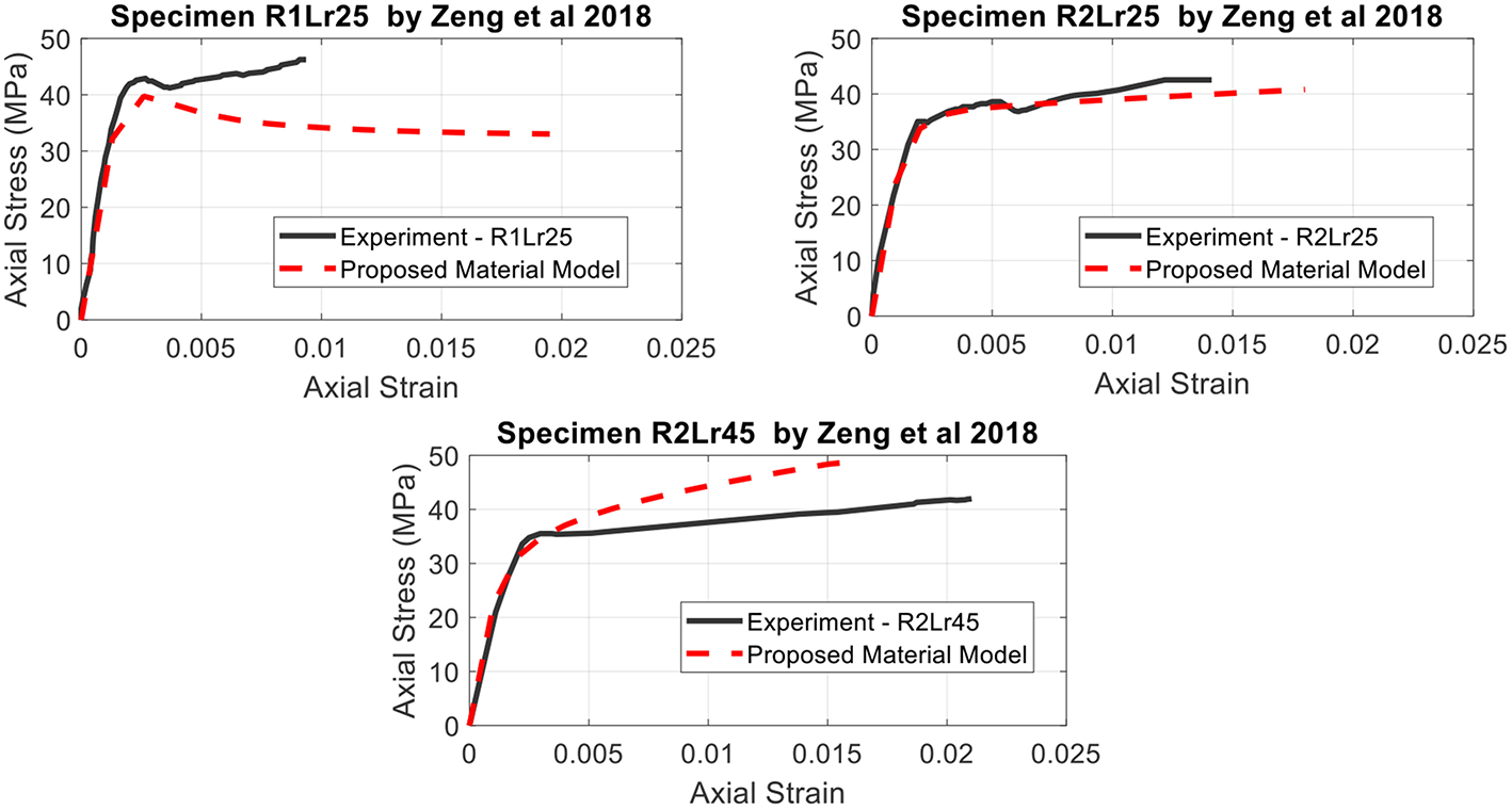
Correlation of the proposed material model with experimental results of large-scale CFRP-confined rectangular RC columns under axial compression by Zeng et al. (2018).
A further evaluation of the model's performance under cyclic lateral loading which simulates earthquake loads and simultaneous constant axial compression was performed. This was achieved by comparison against the experimental tests of FRP-retrofitted square RC columns performed by Memon and Sheikh (2005). This experimental study evaluates the effectiveness of Glass Fiber Reinforced Polymer (GFRP) wraps in strengthening deficient and repairing damaged square RC columns. Each of the eight specimens tested, representing columns of buildings and bridges constructed before 1971, consisted of a 305 × 305 × 1473 mm column connected to a 508 × 762 × 813 mm stub. Specimens were tested under constant axial compression and cyclic lateral displacement excursions simulating earthquake loads.
The modeling of these FRP-confined square RC columns has been performed using the MatLab toolbox FEDEAS lab “Finite Elements for Design Evaluation and Analysis of Structures” (Filippou and Constantinides, 2004). The experimental moment-curvature responses within the plastic hinge regions are reported along with the numerical results in Figure 14. The simulation of the cantilever columns has been applied using a unique fiber beam-column element (Spacone et al., 1996) with force formulation for the entire column, in which the FRP-confined concrete was modeled using the proposed material model with degraded linear unloading/reloading stiffness according to the work of Karsan and Jirsa (1969) and no tensile strength. The constitutive model by Menengotto (1973) is used to model the longitudinal steel behavior. The moment-curvature response of the most critical fiber section of the applied non-linear fiber element was then reported. It can be seen that the agreement is very close to the experimental one, with some deviation concentrated on the parts of reloading after reversal of the imposed displacement. This difference in response in terms of modeling can be explained based on the way the cracks on the concrete surface are described in the level of the material model. Because the crack is described as a two-event phenomenon (open or closed cracks), when the longitudinal steel reinforcement is in compression and the crack is closing, the concrete contributes to the total strength of the column, creating this deviation in the response. In reality, this is not the case due to imperfect crack closure.
Figure 14
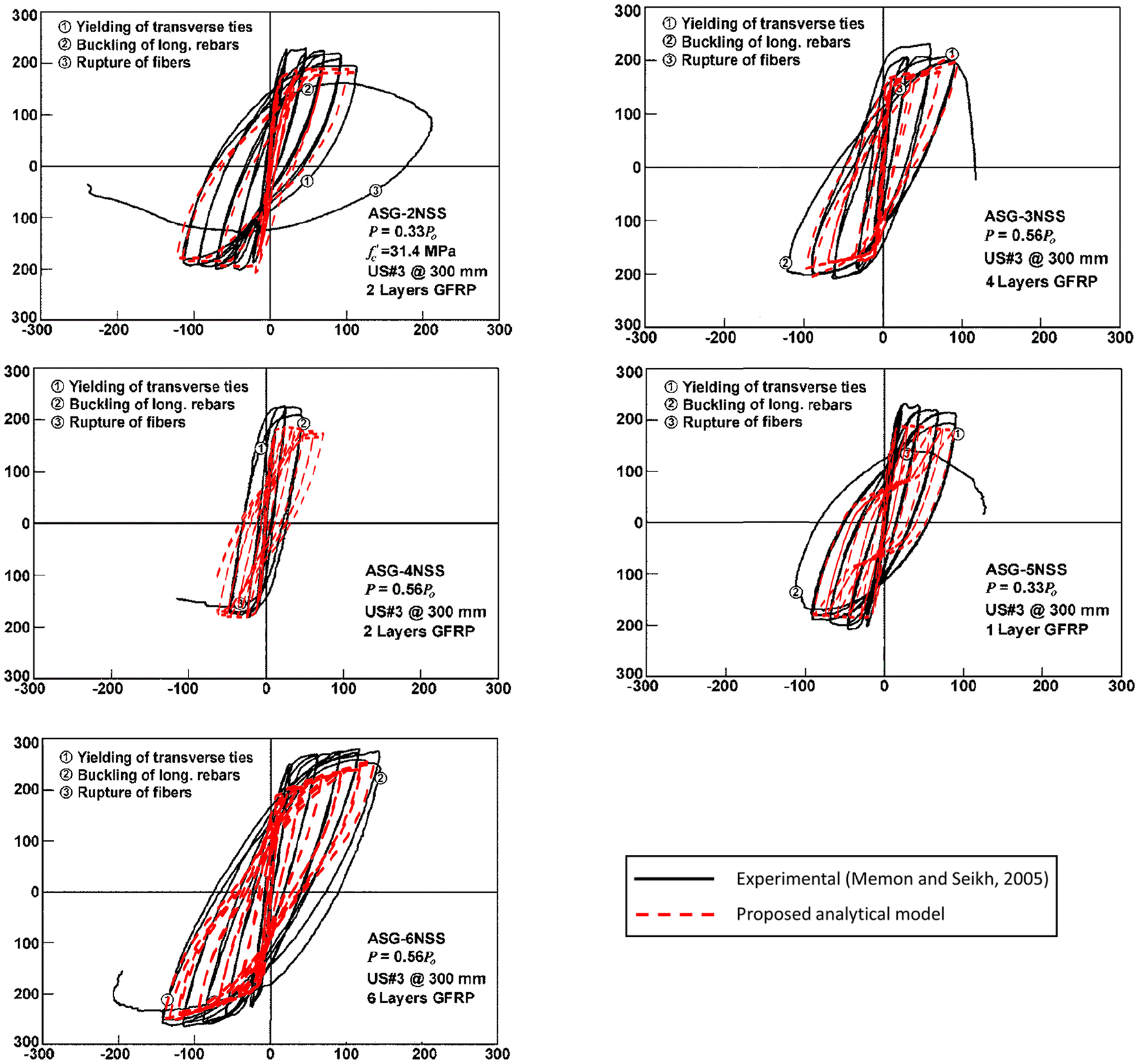
Correlation of the proposed material model with experimental results of large-scale GFRP-confined square RC columns under cyclic excitation by Memon and Sheikh (2005).
Conclusions
An iterative approach was proposed to model both the axial and lateral stress-strain response of axially loaded FRP-confined rectangular and square reinforced concrete columns.
In FRP-confined square or rectangular sections, no unconfined concrete regions are observed, as assumed in many models. These sectors along the sides between adjacent corners are confined from forces coming from the corners and moving parallel to the sides. Therefore, the areas where arching effect is assumed in the section are actually partially confined, so they contribute to the column's total strength until their maximum strength (which is lower than the inner part of the section). Thus, two different regions with different confining stress-states are identified.
The two regions are uniaxially and biaxially confined (biaxial and triaxial stress-state, respectively). Therefore, the contribution of each region to the total section strength can be modeled as a system of parallel springs, whose axial stresses are added based on the corresponding constitutive law under biaxial or triaxial stress state.
The lateral behavior develops along the diagonals of the section and can be represented by a system of springs in series. It was shown that both sides' lateral strains in the rectangular sections are equal, regardless of their aspect ratio. The reacting force of the confining device applied from the corners can be shared among the regions based on the defined path of the confining forces and the geometry of the regions. The resulting lateral uniform pressures lead to the corresponding axial strength of the regions.
The algorithm takes into account all parameters available to designers, such as corner rounding radius, stiffness of the FRP, and concrete strength, while it can be easily understood and implemented. Its results are found to correlate adequately to recent experimental data yielded by large-scale tests on FRP-confined rectangular RC columns. Assessment against small-scale experimental results can be found in Megalooikonomou (2007). Finally, the performance of this material model was further investigated by its implementation to the simulation of a series of experimental tests of FRP-retrofitted square RC columns under cyclic lateral loading simulating earthquake loads and simultaneous constant axial compression. In particular, all specimens were simulated using non-linear fiber elements, in which the FRP-confined concrete was modeled using the developed material model.
Comparison between the numerical and experimental hysteresis of the column is indicative of the effectiveness of the implemented modeling. The model is effective in the modeling of square FRP-confined concrete sections, while it can be applied on the modeling of rectangular sections as well. Its effectiveness can be reduced for large ratio of sides. In particular, for large ratios of the larger side over the smaller side of the column, the proposed model seems to simulate effectively the initial branch of the stress-strain curve, but deviation from the experimental results was observed at the second branch, for larger deformations. Furthermore, it can be applied for various types of FRP wraps such as GFRP and CFRP. It is effective for a large range of FRP thickness that is expected to be met in practice. For sections with large rounding radius at the corners, the proposed model seems to overestimate the contribution of the confinement to the specimen's overall capacity. However, it should be pointed out that such cases are not expected to be met in practice, as the reduced concrete cover sizes defined by the previous design codes, do not allow for a large radius of rounding to be applied on existing reinforced concrete columns. Even though the confinement effectiveness factor (ke) considers the case of a large radius, use of this model in circular sections is not recommended. For circular FRP-confined sections, the readers are referred to Megalooikonomou et al. (2012) and Papavasileiou and Megalooikonomou (2015).
Statements
Author contributions
KGM developed the iterative procedure and performed the comparison and interpretation. GSP contributed to the development of the cyclic constitutive law and its implementation in performing cyclic non-linear static analyses for comparison with experimental results. All the authors read and approved the final manuscript.
Funding
This research was conducted with the financial support of the Alexander S. Onassis Public Benefit Foundation which provided KGM with a triennial scholarship (Scholarship Code: F ZI 086-1 2012-2013/ 01/09/2012–29/02/2016) to pursue a Ph.D. degree in Civil Engineering at the University of Cyprus.
Acknowledgments
The first author would like to thank the Alexander S. Onassis Public Benefit Foundation whose financial support is greatly appreciated. The present research work is based on the masters' thesis of KGM (Megalooikonomou, 2007), which was extended to simulate the cyclic response of FRP-confined rectangular RC columns.
Conflict of interest
The authors declare that the research was conducted in the absence of any commercial or financial relationships that could be construed as a potential conflict of interest.
References
1
Campione G. Miraglia N. (2003). Strength and strain capacities of concrete compression members reinforced with FRP. Cement Concrete Compos.25, 31–41. 10.1016/S0958-9465(01)00048-8
2
Chaallal O. Shahawy M. Al-Saad N. (2000). Behaviour of Axially Loaded Short Rectangular Columns Strengthened With CFRP Composite Wrapping. FDOT, Structures Research Center, Tallahassee.
3
Chaallal O. Shahawy M. Hassan M. (2003). Performance of axially loaded short rectangular columns strengthened with carbon fiber-reinforced polymer wrapping. J. Compos. Construct.7, 200–208. 10.1061/(ASCE)1090-0268(2003)7:3(200)
4
Computers and Structures Inc . (2016). CSI Analysis Reference Manual. Berkeley, CA: Taylor and Francis.
5
De Luca A. Nardone F. Matta F. Nanni A. Lignola G. P. Prota A. (2011). Structural evaluation of full-scale FRP-confined reinforced concrete columns. J. Compos. Construct.15, 112–123. 10.1061/(ASCE)CC.1943-5614.0000152
6
Eid R. Paultre P. (2017). Compressive behavior of FRP-confined reinforced concrete columns. Eng. Struct.132, 518–530. 10.1016/j.engstruct.2016.11.052
7
Fahmy M. F. Ismail A. M. Wu Z. (2017). Numerical study on the applicability of design-oriented models of FRP-confined concrete for predicting the cyclic response of circular FRP-jacketed RC columns. J. Compos. Construct.21:04017017. 10.1061/(ASCE)CC.1943-5614.0000791
8
Farahmandpour C. Dartois S. Quiertant M. Berthaud Y. Dumontet H. (2017). A concrete damage–plasticity model for FRP confined columns. Mater. Struct.50:156. 10.1617/s11527-017-1016-8
9
Filippou F. C. Constantinides M. (2004). FEDEASLab getting started guide and simulation examples. NEESgrid Rep.22, 2004–2005.
10
Hany N. F. Hantouche E. G. Harajli M. H. (2016). Finite element modeling of FRP-confined concrete using modified concrete damaged plasticity. Eng. Struct.125, 1–14. 10.1016/j.engstruct.2016.06.047
11
Hosotani M. Kawashima K. Hoshikuma J. (1997). A study on confinement effect of concrete cylinders by carbon fiber sheets. Non-Metallic (FRP). Reinforce. Concrete Struct.1, 209–216.
12
Ismail A. M. Fahmy M. F. Wu Z. (2017). Simulating the lateral performance of FRP-confined RC circular columns using a new eccentric-based stress-strain model. Compos. Struct.180, 88–104. 10.1016/j.compstruct.2017.07.075
13
Jiang J. F. Wu Y. F. (2012). Identification of material parameters for Drucker–Prager plasticity model for FRP confined circular concrete columns. Int. J. Solids Struct.49, 445–456. 10.1016/j.ijsolstr.2011.10.002
14
Karabinis A. I. Kiousis P. D. (1996). Strength and ductility of rectangular concrete columns: a plasticity approach. J. Struct. Eng.122, 267–274. 10.1061/(ASCE)0733-9445(1996)122:3(267)
15
Karabinis A. I. Rousakis T. C. Manolitsi G. E. (2008). 3D finite-element analysis of substandard RC columns strengthened by fiber-reinforced polymer sheets. J. Compos. Construct.12, 531–540. 10.1061/(ASCE)1090-0268(2008)12:5(531)
16
Karam G. Tabbara M. (2005). Confinement effectiveness in rectangular concrete columns with fiber reinforced polymer wraps. J. Compos. Construct.9, 388–396. 10.1061/(ASCE)1090-0268(2005)9:5(388)
17
Karsan I. D. Jirsa J. O. (1969). Behavior of concrete under compressive loadings. J. Struct. Division95, 2543–2564.
18
Kupfer H. Hilsdorf H. K. Rusch H. (1969). Behavior of concrete under biaxial stresses. In ACI J. Vol. 66, 656–666. 10.14359/88
19
Lam L. Teng J. G. (2003a). Design-oriented stress-strain model for FRP-confined concrete in rectangular columns. J. Reinforced Plastics Compos.22, 1149–1186. 10.1177/0731684403035429
20
Lam L. Teng J. G. (2003b). Design-oriented stress–strain model for FRP-confined concrete. Construct. Build. Mater.17, 471–489. 10.1016/S0950-0618(03)00045-X
21
Liu T. C. Nilson A. H. Slate F. O. (1972). Biaxial stress-strain relations for concrete. J. Struct. Division98, 1025–1034.
22
Mander J. B. Priestley M. J. N. Park R. (1988). Observed stress-strain behavior of confined concrete. J. Struct. En.114, 1827–1849. 10.1061/(ASCE)0733-9445(1988)114:8(1827)
23
Megalooikonomou K. G. Kim K. D. Monti G. (2007). “Stress-Strain Model for FRP-confined Rectangular RC Sections via an Incremental Procedure,” in Asia-Pacific Conference on FRP in Structures (APFIS 2007) (Hong Kong).
24
Megalooikonomou K. G. Monti G. Santini S. (2012). Constitutive Model for Fiber-reinforced polymer-and Tie-confined concrete. ACI Struct. J.109, 569–578. 10.14359/51683876
25
Megalooikonomou K. G. (2007). Modelling of FRP-Confinement of Rectangular RC Sections. Master Thesis, European School for Advanced Studies in Reduction of Seismic Risk (ROSE School), University of Pavia, Pavia. Available online at: http://www.roseschool.it/page/202/modelling-of-frp-confinement-of-rectangular-rc-sections.html
26
Memon M. S. Sheikh S. A. (2005). Seismic resistance of square concrete columns retrofitted with glass fiber-reinforced polymer. ACI Struct. J.102, 774–783. 10.14359/14673
27
Menengotto M. (1973). “Method of analysis for cyclically loaded reinforced concrete plane frames including changes in geometry and nonelastic behavior of elements under combined normal force and bending,” in IABSE Symposium on Resistance and Ultimate Deformability of Structures Acted on by Well-Defined Repeated Loads, Final Report (Lisbon).
28
Mirmiran A. Shahawy M. Samaan M. Echary H. E. Mastrapa J. C. Pico O. (1998). Effect of column parameters on FRP-confined concrete. J. Compos. Construct.2, 175–185. 10.1061/(ASCE)1090-0268(1998)2:4(175)
29
Nisticò N. Monti G. (2014). RC square sections confined by FRP: analytical prediction of peak strength. Compos. Part B. Eng.45, 127–137. 10.1016/j.compositesb.2012.09.041
30
Ottosen N. S. (1977). A failure criterion for concrete. Am. Soc. Civil Eng. Eng. Mech. Division J.103, 527–535.
31
Ozbakkaloglu T. Gholampour A. Lim J. C. (2016). Damage-plasticity model for FRP-confined normal-strength and high-strength concrete. J. Compos. Construct.20:04016053. 10.1061/(ASCE)CC.1943-5614.0000712
32
Ozbakkaloglu T. Lim J. C. (2013). Axial compressive behavior of FRP-confined concrete: experimental test database and a new design-oriented model. Compos. Part B Eng.55, 607–634. 10.1016/j.compositesb.2013.07.025
33
Ozbakkaloglu T. Lim J. C. Vincent T. (2013). FRP-confined concrete in circular sections: review and assessment of stress–strain models. Eng. Struct.49, 1068–1088. 10.1016/j.engstruct.2012.06.010
34
Pantazopoulou S. J. Mills R. H. (1995). Microstructural aspects of the mechanical response of plain concrete. Mater. J.92, 605–616. 10.14359/9780
35
Papavasileiou G. S. Megalooikonomou K. G. (2015). “Numerical simulation of FRP-confined circular bridge piers using opensees,” in Proc. OpenSees Days Italy (OSD), Second International Conference, University of Salerno (Salerno).
36
Parvin A. Wang W. (2001). Behavior of FRP jacketed concrete columns under eccentric loading. J. Compos. Construct.5, 146–152. 10.1061/(ASCE)1090-0268(2001)5:3(146)
37
Parvin A. Wang W. (2002). “Tests on concrete square columns confined by composite wraps,” in Proc. 3rd International Conf. on Composites in Infrastructure ICCI'02 (San Francisco, CA).
38
Piscesa B. Attard M. M. Samani A. K. (2018). 3D Finite element modeling of circular reinforced concrete columns confined with FRP using a plasticity based formulation. Compos. Struct.194, 478–493. 10.1016/j.compstruct.2018.04.039
39
Popovics S. (1973). A numerical approach to the complete stress-strain curve of concrete. Cement Concrete Res.3, 583–599. 10.1016/0008-8846(73)90096-3
40
Richart F. E. Brandtzaeg A. Brown R. L. (1928). A Study of the Failure of Concrete Under Combined Compressive Stresses.University of Illinois at Urbana Champaign, College of Engineering. Engineering Experiment Station Bulletin No. 185, University of Illinois, Urbana. Available online at: http://hdl.handle.net/2142/4277
41
Rochette P. Labossiere P. (2000). Axial testing of rectangular column models confined with composites. J. Compos. Construct.4, 129–136. 10.1061/(ASCE)1090-0268(2000)4:3(129)
42
Rousakis T. C. Rakitzis T. D. Karabinis A. I. (2012). Design - oriented strength model for FRP confined concrete members. J. Compos. Construct.16, 615–625. 10.1061/(ASCE)CC.1943-5614.0000295
43
Rousakis T. C. Tourtouras I. S. (2015). Modeling of passive and active external confinement of RC columns with elastic material. ZAMM J. Appl. Math. Mech.95, 1046–1057. 10.1002/zamm.201500014
44
Roussakis T. C. Karabinis A. I. Kiousis P. D. Tepfers R. (2008). Analytical modelling of plastic behaviour of uniformly FRP confined concrete members. Compos. B Eng.39, 1104–1113. 10.1016/j.compositesb.2008.05.001
45
Samaan M. Mirmiran A. Shahawy M. (1998). Model of concrete confined by fiber composites. J. Struct. Eng.124, 1025–1031. 10.1061/(ASCE)0733-9445(1998)124:9(1025)
46
Spacone E. Filippou F. C. Taucer F. F. (1996). Fibre beam–column model for non-linear analysis of R/C frames: part I. Formulation. Earthquake Eng. Struct. Dyn.25, 711–725. 10.1002/(SICI)1096-9845(199607)25:7<711::AID-EQE576>3.0.CO;2-9
47
Spoelstra M. R. Monti G. (1999). FRP-confined concrete model. J. Compos. Construct.3, 143–150. 10.1061/(ASCE)1090-0268(1999)3:3(143)
48
Teng J. G. Chen J. F. Smith S. T. Lam L. (2002). FRP-Strengthened RC Structures. Chichester: John Wiley and Sons Inc.
49
Teng J. G. Lam L. (2004). Behavior and modeling of fiber reinforced polymer-confined concrete. J. Struct. Eng.130, 1713–1723. 10.1061/(ASCE)0733-9445(2004)130:11(1713)
50
Teng J. G. Zeng J. J. Chen J. F. (2015). “Measurement of axial stress distributions in FRP-confined concrete columns using Tekscan pressure sensors,” in Proceedings of the Joint Conference of FRPRCS-12 and APFIS-2015 (Nanjing), 14–16.
51
Vintzileou E. Panagiotidou E. (2008). An empirical model for predicting the mechanical properties of FRP-confined concrete. Construct. Build. Mater.22, 841–854. 10.1016/j.conbuildmat.2006.12.009
52
Wang Z. Wang D. Smith S. T. Lu D. (2011). CFRP-confined square RC columns. II: cyclic axial compression stress-strain model. J. Compos. Construct.16, 161–170. 10.1061/(ASCE)CC.1943-5614.0000246
53
Yu T. Teng J. G. Wong Y. L. Dong S. L. (2010b). Finite element modeling of confined concrete-II: plastic-damage model. Eng. Struct.32, 680–691. 10.1016/j.engstruct.2009.11.013
54
Yu T. Teng J. G. Teng J. G. Wong Y. L. Dong S. L. (2010a). Finite element modeling of confined concrete-I: drucker–prager type plasticity model. Eng. Struct.32, 665–679. 10.1016/j.engstruct.2009.11.014
55
Zeng J. J. Lin G. Teng J. G. Li L. J. (2018). Behavior of large-scale FRP-confined rectangular RC columns under axial compression. Eng. Struct.174, 629–645. 10.1016/j.engstruct.2018.07.086
Summary
Keywords
confinement, FRP, concrete, rectangular, model, stress-strain behavior
Citation
Megalooikonomou KG and Papavasileiou GS (2019) Analytical Stress-Strain Model for FRP-Confined Rectangular RC Columns. Front. Built Environ. 5:39. doi: 10.3389/fbuil.2019.00039
Received
14 December 2018
Accepted
07 March 2019
Published
12 April 2019
Volume
5 - 2019
Edited by
Luigi Di Sarno, University of Sannio, Italy
Reviewed by
Flora Faleschini, University of Padova, Italy; Theodoros C. Rousakis, Democritus University of Thrace, Greece
Updates
Copyright
© 2019 Megalooikonomou and Papavasileiou.
This is an open-access article distributed under the terms of the Creative Commons Attribution License (CC BY). The use, distribution or reproduction in other forums is permitted, provided the original author(s) and the copyright owner(s) are credited and that the original publication in this journal is cited, in accordance with accepted academic practice. No use, distribution or reproduction is permitted which does not comply with these terms.
*Correspondence: Konstantinos G. Megalooikonomou kmegal@gfz-potsdam.de
This article was submitted to Earthquake Engineering, a section of the journal Frontiers in Built Environment
Disclaimer
All claims expressed in this article are solely those of the authors and do not necessarily represent those of their affiliated organizations, or those of the publisher, the editors and the reviewers. Any product that may be evaluated in this article or claim that may be made by its manufacturer is not guaranteed or endorsed by the publisher.