 Giuseppe Campione1
 Alessia Monaco
- 1Department of Civil, Environmental, Aerospace and Material Engineering, University of Palermo, Palermo, Italy
- 2Department of Architecture and Design, Polytechnic of Turin, Turin, Italy
This paper presents the criteria for the shear design of high strength concrete (HSC) beams in moment resisting frames (MRFs). The formulation of an analytical model is provided for the case of beams with longitudinal reinforcement in the presence of transverse stirrups. The model is of additive type, in the meaning that the shear resistance of the beam is evaluated as the sum of several contributions. In particular, the contribution of concrete, longitudinal rebars, and transversal reinforcement are taken into account. Furthermore, for assessing the concrete contribution, a classical approach is followed, according to which two effects arise in the shear mechanism: the arc and the beam effect. The features of these two resisting mechanisms are particularized to the case of HSC in steel reinforced beams and the maximum concrete contribution is limited to the maximum compressive strength of the concrete strut in biaxial state of stress. Moreover, for the evaluation of the resistance contribution of the longitudinal steel rebars in tension, the model takes into account the residual bond adherence between HSC and steel reinforcement and the spacing between subsequent cracks. The results are compared with the prescriptions currently provided in the main building codes and with different analytical models existing in the literature. For the comparison, the analytical expressions are applied to a set of experimental data available in the literature and design observations are made on the geometrical percentage of steel bars, the resistance of materials, the residual bond stress and the depth-to-shear span ratio.
Introduction
High Strength Concrete (HSC) is increasingly used in the construction industry thanks to its advantages. This type of concrete is usually manufactured with a low water-to-cement ratio and has high compressive strength in the range of 50 to 100 MPa. In comparison with normal strength concrete (NSC), HSC has increased modulus of elasticity, chemical resistance, freeze thaw resistance, lower creep, lower drying shrinkage, and lower permeability.
HSC is also used in moment resisting frames (MRFs) subjected to both monotonic and cyclic loads. It is well–known that in MRFs the presence of shear may cause a significant reduction of the beam flexural strength with respect to the pure flexure case and, therefore, beams may undergo to brittle failure without any warning signs Ahmad and Lue (1987). Such a complex phenomenon has been investigated in a great number of researches with particular regard to the case of beams reinforced only through longitudinal rebars. Among others, in Hong and Ha (2012), Kunthia et al. (1999), Kunthia and Stajadinovic (2001), Mphonde and Frantz (1986) the so called “concrete mechanisms” are investigated. For beams made up of HSC, the analytical expressions currently given in the main building codes for the shear strength prediction can give non-conservative values of the shear strength, as shown in some recent studies available in the literature (Zararis, 2003; Arslan, 2008; Russo et al., 2013). Therefore, some authors have recently proposed reliable expressions for the calculation of the shear resistance of HSC beams, even though limiting the study to the case of beam without stirrups (Mphonde and Frantz, 1986; Kunthia et al., 1999).
In this paper, the research is addressed toward the evaluation of the resisting contribution provided not only by concrete and longitudinal rebars in the “concrete mechanism” but also by the transversal reinforcement generally made in form of transversal stirrups spaced along the beam axis. The strength provided by the transversal reinforcement can be taken into account by adding the contribution of the so called “truss mechanism” to the analytical model. Therefore, an analytical formula for the shear strength prediction of HSC beams in MRFs is presented. The analytical model has the advantage of being based on simplified mechanical schemes rather than on complex empirical equations (Ahmad and Lue, 1987). Many equations have been proposed in the literature for the assessment of the ultimate shear strength of RC beams. Among others, Zsutty's (1968) equation derives from multiple regression analyses; Bazant's equation (derived by Bazant and Kim) is based on non-linear fracture mechanics and accounts for the size effect in the resisting mechanism; the CEB-FIP model code equation makes use of coefficients empirically obtained. In this paper, the nominal shear strength of RC beams with stirrups is assumed as the sum of two distinct contributions: the resistance of stirrups resulting from the truss action and the concrete resistance. The latter is a contribution of paramount importance in the design of RC beams where the shear force is close to the value required for inducing diagonal tension cracking. In a study previously conducted by Arslan (2008), the equations for the prediction of the cracking shear strength performed almost as well as the ACI Committee 318 (2008) simplified equation in terms of coefficient of variation; conversely, in terms of mean value, ACI 318 provided a shear strength prediction generally more conservative than the calculation obtained with Arslan's equations. In the present study, Arslan's cracking shear strength equations are used to take into account the concrete contribution while the contribution of stirrups is added to the concrete contribution to obtain the shear strength of HSC reinforced beams. The shear strength values predicted through the analytical model are finally compared with the results of shear tests on RC beams with stirrups available in the literature (Elzanaty et al., 1986; Mphonde and Frantz, 1986; Ahmad and Lue, 1987; Yoon et al., 1996; Pendyala and Mendis, 2000; Zararis, 2003; Hong and Ha, 2012).
Analytical Model
The classical approach for the calculation of the shear capacity of RC beams was proposed by Bazant and Kim (1984). Their analytical approach is based on a mechanical model in which the concrete contribution is given by the sum of two effects: arch and beam action, respectively. Such resisting mechanisms are depicted in Figure 1.
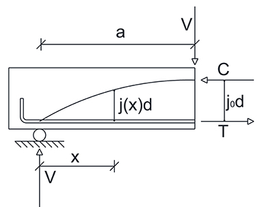
Figure 1. Arch and beam effects.
In particular, for the equilibrium of a portion of the beam within the shear span a, the following equation must be satisfied for every cross-section:
where the shear force V is related to the bending moment M through the following relationship:
In Equation (2) the two contributions of arch and beam effect are individuated. In particular, the beam effect is herein denoted as:
where the term j0d is constant, while the tensile force T is variable. Therefore, for the calculation of V1 it is necessary to evaluate the variation of the tensile force, as shown in Figure 2.
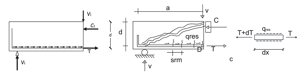
Figure 2. Beam effect contributions.
The variation of the tensile force can be calculated assuming the condition of bond splitting failure, i.e., considering the residual splitting bond stresses qres transmitted by the longitudinal bar:
where Di is the diameter of the i-th bar belonging to the main reinforcements of the area As. Therefore, using Equation (3) and Equation (4) the following expression is obtained for the beam effect resisting contribution:
For evaluating the contribution of v1 it is necessary to assess the residual bond stresses qres. In the well-known study by Eligehausen et al. (1983) for ordinary concrete, it is shown that the splitting bond stresses are proportional to the square root of the cylindrical compressive resistance while other studies and codes such as (Eurocode 2, 2004) assume qres to be proportional to the power 1/3. For HSC Harajli (2004) demonstrated that the splitting stresses are equal to:
δ being the cover of the longitudinal bars and Di the equivalent diameter of the longitudinal bars. Therefore, if is assumed, then the bond stresses can be calculated as . Such a value can be comparable with the value of the tensile strength of the material (ACI Committee 318, 2008) adopting a proper reduction coefficient (in this case 0.33) and such evidence is additionally motivated with the mechanical model that rules the bond splitting failure.
Other authors suggest similar expressions for taking into account the bond splitting failure in the calculation of the shear strength. Chunmin and Leping (2011) suggest the following expression:
where ft is the tensile strength of the concrete that can be assumed as in the ACI Committee 318 (2008) code in the form . Therefore, the shear strength is equal to:
A similar expression is obtained by Hong and Ha (2012), assuming a splitting bond failure when the circumferential tensile stresses reach the tensile strength of the concrete:
Finally, in ACI Committee 318 (2008) the same expression as Equation (10) is used assuming the coefficient 1/7 instead of 0.2.
In Figure 3 the different models are compared showing the shear strength with the variation of the geometrical ratio of steel rebar according to Equations (6), (9), (10) and ACI Committee 318 (2008) prescriptions: the comparison shows that for low percentages of steel the shear strength is overestimated while for ρ > 0.025 the limit appears appropriate.
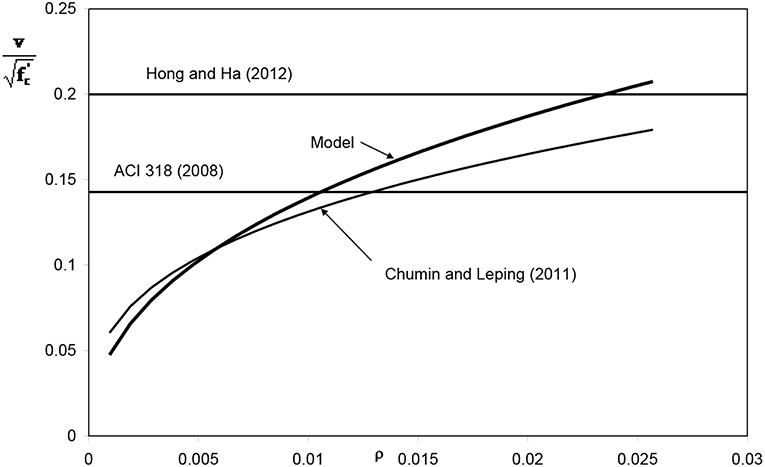
Figure 3. Variation in shear strength due to bond splitting vs. geometrical ratio of steel bars.
If the effect of corrosion has to be considered, the residual splitting stresses can be assessed as in Coronelli (2002) considering the deterioration due to corrosion as shown in Figure 4 where qres is indicated as . In this case, the expression originally proposed by Rodriguez et al. (1994) can be used:
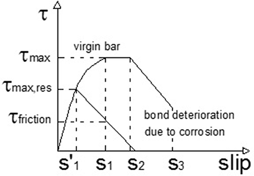
Figure 4. Bond deterioration due to corrosion.
The residual bond stress is evaluated as the sum of two contributions: the concrete contribution on one hand and the contribution to bond given by the transverse stirrups. The splitting stresses also depend on the X factor which is the corrosion attack penetration. Finally in Equation (11) fct is the concrete tensile strength, Asw and fyw are the reduced area and yielding stress of stirrups (ACI Committee 318, 2008) placed at a spacing s and β, μ, k are empirical constants.
For the evaluation of the total shear resistance according to Equation (2) it is now necessary to evaluate the second contribution V2 named arch effect:
With reference to Equation (12), an analytical variation law for the internal lever arm j should be derived. Using the formulation by Bazant and Kim (1984), the variation of j can be assumed as:
with α = 1 in case of linear variation, as assumed by Swamy et al. (1993).
Moreover, the assessment of the traction force can be made considering the steel contribution as Ts = σs · ρ · b · d where σs is the stress in the longitudinal bar. The latter is difficult to be evaluated because it depends on the residual bond stresses within the crack spacing srm. The crack spacing can be determined as suggested in Eurocode 2 (2004) and, therefore, the stress in the longitudinal bars can be calculated as:
with and .
The equilibrium of internal forces in the crack spacing can be written as:
Therefore, substituting Equations (13)–(15) into Equation (12) the following expression can be derived for the arch effect contribution:
Finally, the shear resistance vc can be obtained by the sum of Equations (6) and (16).
In this model, an upper limit for the shear strength can be imposed considering the concrete crushing. In particular, the ultimate axial force in the concrete strut is calculated as:
where υ is a softening coefficient, which can be set equal to 0.5 according to Eurocode 2 (2004) and .
For the equilibrium of the forces Vu = Nu · sinα and therefore the ultimate shear stress related to the arch crushing is:
Model Validation
In the following sections, the most adopted expressions for the prediction of the flexural and shear strength of HSC beams are presented and compared with those of the current model. Successively, the results of experimental tests on RC beams with transversal stirrups are described and used for the validation of the analytical models.
Analytical Benchmarks
For the analytical evaluation of the flexural strength, the most common building codes distinguish the case of over-reinforced and under-reinforced cross-sections. When beams designed in practice are under-reinforced, the yield force in the tensile steel controls their flexural strength. In these cases, most of the current codes make use of the stress-block approach for determining the ultimate flexural capacity of the beam, neglect the limited contribution of the compressed bars (see Figure 5).
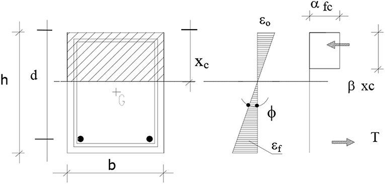
Figure 5. Stress-block approach for the calculation of the flexural strength.
With reference to the symbols used in Figure 5, the equilibrium of the cross-section is given by:
In Equations (19, 20), Mu is the ultimate bending moment and xc is the neutral axis depth while the other symbols are: As the area of longitudinal tensile bars, b the width of the beam, d the effective depth α and β the stress block coefficients. In Table 1, the most common values of α, β, and εcu ultimate compressive strain of concrete) are given for several codes and authors.
Table 1. Stress-block parameters.
Equations (19, 20) can be also written as function of the mechanical ratio of the main steel and therefore the following expressions can be derived:
with
Moreover, the following condition should be satisfied:
Equation (23) is verified when the steel bars are considered to have yielded and the concrete to be crushed.
Using Equations (21) and (23) the limit geometrical ratio of the longitudinal steel can be obtained:
As regards the shear strength, for the concrete contribution ACI Committee 318 (2008) suggests:
while for the stirrup contribution it is assumed:
Therefore, in ACI Committee 318 (2008) the shear strength is expressed as the sum of concrete and stirrup contributions:
Similarly, Canadian Standards Association (2004) are based on the shear resisting mechanism consisting in a free body diagram of the end portion of a beam. This portion cuts the flexural compression region and the longitudinal reinforcement and stirrups following the diagonal shear crack. If the dowel action is neglected, the shear strength equation is:
where φc, φs are material reduction factors for concrete and steel stirrups, β represents the ability of the member to resist aggregate interlock stresses and θ is the angle of principal compressive stresses. For the calculation of β and θ, the formulation by Bentz and Collins (2006) can be assumed.
In Eurocode 2 (2004) the variable strut inclination method is assumed. According to this method the shear strength is calculated as the minimum value between:
Some other expressions are those in Zararis (2003), Arslan (2008), and Russo et al. (2013). In particular, Zararis (2003) shows that the nominal shear stress at diagonal tension cracking is the product of the ratio of the neutral axis depth to the effective depth of the beam and the splitting tensile strength of the concrete. The contribution of stirrups which are assumed to have yielded is considered in the splitting region and the expression of the shear strength proves to be:
where is a term used for taking into account the size effect.
Arslan (2008) calculates the shear strength of slender beams and considers the stirrups yielded and the main crack inclined at an angle of 45°. Therefore, the following expression is obtained:
Finally, according to Russo et al. (2013) the shear strength can be calculated through a quite complex formula depending on empirical coefficient:
in which da represents the maximum aggregate size and a is the shear span.
Comparison With Experimental Data
Experimental data available in the literature are used for validating the expressions of the flexural and shear capacity prediction. In particular, for the flexural strength, the experimental results provided by Sarkar and Adwan (1997), Pam et al. (2001), Ashour (2000), and Bernardo and Lopes (2004) from are considered. All tests are conducted on under-reinforced beams with concrete compressive strength between 36 and 107 MPa, effective depth between 215 and 26 mm, steel percentage ρ between 0.76 and 3.61% and yielding stress fy between 300 and 579 MPa. The results obtained are plotted in the graphs of Figure 6 where the ratio between experimental and analytical moment is shown with the variation of the compressive strength (Figure 6A) and the steel percentage (Figure 6B). In particular, from Figure 6A it can be observed a progressive increase in the underestimation of the moment capacity as the concrete strength increases (see the best fitting line). Conversely, from Figure 6B it can be observed that the limit of 0.025 [i.e., the upper limit indicated by ACI Committee 318 (2008)] is too much conservative to ensure that steel bars yield before the crushing of concrete and therefore higher values could be adopted even though, for the design of members in seismic area, this limitation should be adequately checked.
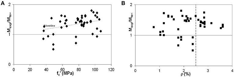
Figure 6. Variation of the ratio between experimental and analytical moment with: (A) concrete compressive strength; (B) steel reinforcement percentage.
Finally, Table 2 reports the mean values and the coefficients of variation for all examined cases. In general, it can be observed that all models underestimate the effective flexural capacity of beams and, in most cases, conservative results are obtained.
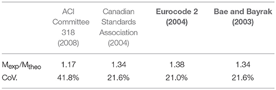
Table 2. Flexural strength prediction.
For the validation of the shear models, the experimental results used by Zararis (2003) and those available in Mphonde and Frantz (1986), Elzanaty et al. (1986), Ahmad and Lue (1987), Yoon et al. (1996), Pendyala and Mendis (2000), and Hong and Ha (2012) were considered. The data used by Zararis (2003) refer to specimens with concrete compressive strength between 12.8 and 103 MPa, effective depth between 95 and 1200 mm, a/d between 2.4 and 5.05, ρ between 0.5 and 4.54%, ρv between 0.06 and 0.84, fy between 242 and 844 MPa. Conversely, the other data refer to specimens with concrete compressive strength between 40 and 94 MPa, effective depth between 160 and a/d between 2 and 6, ρ between 0.6 and 6.64 %, ρv between 0.08 and 1, fy between 370 and 430 MPa.
Figure 7 shows the variation of the ultimate experimental shear strength vs. the analytical prediction calculated with all models. Table 3 reports the mean values and the coefficients of variations for all examined cases. From the results it emerges that most of the expressions proposed are able to predict the shear strength of beams quite accurately.
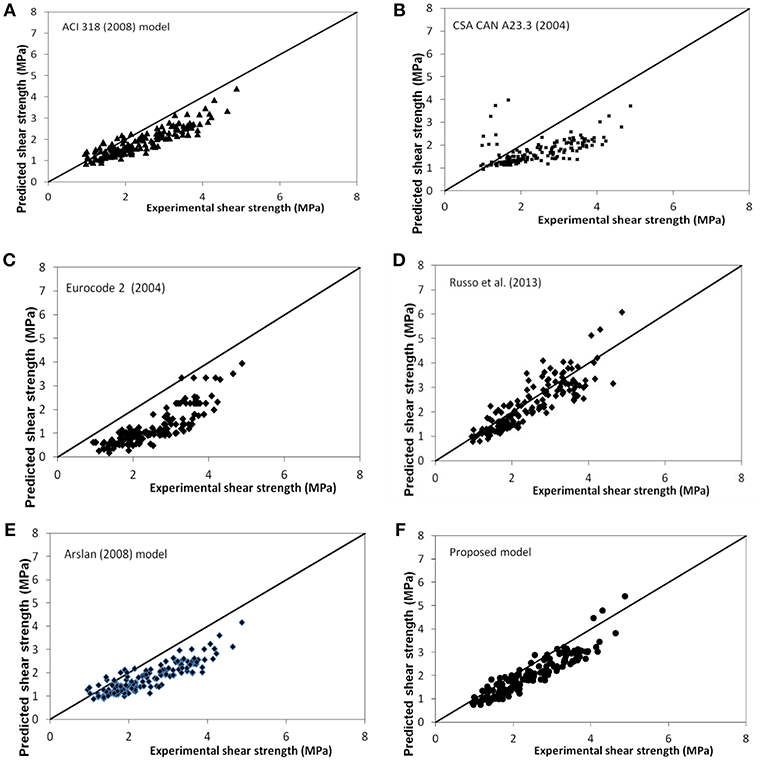
Figure 7. Variation of the ratio between experimental and analytical shear stress according to: (A) (ACI Committee 318, 2008) (B) (Canadian Standards Association, 2004) (C) Eurocode 2 (2004), (D) Russo et al. (2013); (E) Arslan (2008); (F) proposed model.
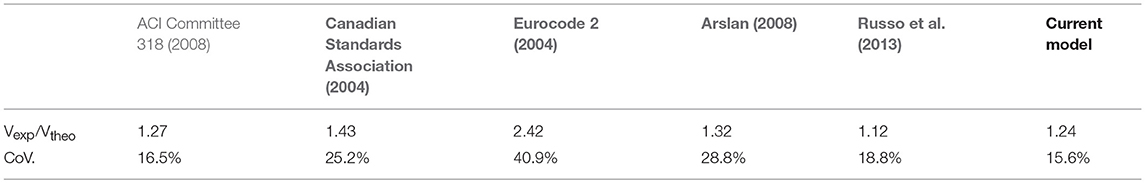
Table 3. Shear strength prediction.
Finally, Figure 8 shows the variation of the ultimate shear stress dimensionless with respect to vs. the mechanical ratio of the stirrups ρswfsw. In the same graph, the prediction with the current model and with Russo et al. (2013) and Zararis (2003) models are given. The best fitting line is also represented. It has to be stressed that all experimental data are in the range expected with Zararis (2003) model, while in several cases Russo et al. (2013) model overestimates the experimental shear strength of the beams. Conversely, the proposed model gives the most conservative results.
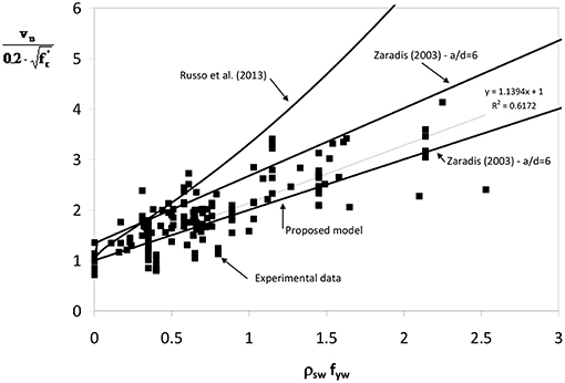
Figure 8. Variation of the ultimate shear stress against ρ swfsw.
In this paper an analytical model is provided for the calculation of the flexural and shear capacity of HSC beams in the presence of transversal reinforcement. The model is given in additive form, assuming two different contributions in the shear resistance, i.e., the shear capacity provided by the concrete and the contribution due to the transversal stirrups. The shear strength of concrete is calculated following the classical approach originally proposed by Bazant and Kim (1984), determining two resisting mechanisms named “arch” and “beam” action. The model also takes into account the crushing of concrete by introducing an upper limit to the contribution of the material in compression. For the validation of the model, several analytical formulations available in the literature are reviewed and the models are applied for interpreting the results of a set of experimental data in the literature. The comparison shows that there is an increasing underestimation of the flexural capacity of the beam for increasing values of the concrete compressive strength; the results also show that the limit of 2.5% for the steel ratio is excessively conservative to ensure the yielding of the steel reinforcement before the crushing of concrete, even though in seismic areas this limit should be carefully checked. Finally, all models for the prediction of the shear strength are able to provide quite accurate results. In particular the model proposed by Russo et al. (2013) gives the most accurate mean value of the ratio between experimental and theoretical shear resistance, equal to 1.12, while the current model gives a quite accurate mean value (equal to 1.24) and proves to be the most reliable model with the lowest value of coefficient of variation which is equal to 15.6%. Finally the current model is able to provide the most conservative result in terms of non-dimensional ultimate shear stress with the variation of the mechanical ratio of transversal reinforcement.
Author Contributions
GC: principal investigator. CC and AM: secondary investigators. AM: performer of the analyses and writer of the paper.
Conflict of Interest Statement
The authors declare that the research was conducted in the absence of any commercial or financial relationships that could be construed as a potential conflict of interest.
References
ACI Committee 318 (2008). Bulding Code Requirements for Structural Concrete and Commentary. Framington Hills, MI: American Concrete Institute.
Ahmad, S. H., and Lue, D. M. (1987). Flexural-shear interaction of reinforced high strength concrete beams. ACI Struct. J. 84, 330–341.
Arslan, G. (2008). Shear strength of reinforced concrete beams with stirrups. Mater. Struct. 41, 113–122. doi: 10.1617/s11527-007-9223-3
Ashour, S. A. (2000). Effect of compressive strength and tensile reinforcement ratio on flexural behavior of high strength concrete beams. Eng. Struct. 22, 413–423. doi: 10.1016/S0141-0296(98)00135-7
Bae, S., and Bayrak, O. (2003). Stress block parameters for high-strength concrete members. ACI Struct. J. 100, 626–636. doi: 10.14359/12804
Bazant, Z. P., and Kim, S. S. (1984). Size effect in shear failure of longitudinally reinforced beams. ACI Struct J. 81, 456–468.
Bentz, E. C., and Collins, M. P. (2006). “Simplified form of the modified compression field theory (MCFT) for the analysis of beams,” in ID 3-56 of Proceeding of Second International. Naples.
Bernardo, L. F. A., and Lopes, S. M. R. (2004). Neutral axis depth versus-flexural ductility in high strength concrete beams. ASCE J. Struct. Eng. 130, 425–459. doi: 10.1061/(ASCE)0733-9445(2004)130:3(452)
Canadian Standards Association (2004). CAN CSA A23.3-04 Design of Concrete Structures. Ontario: CSA.
Chunmin, D., and Leping, N. (2011). “A general shear strength method for reinforced concrete beams,” in 2011 International Conference on Electric Technology Civil Engineering, ICETCE 2011 - Proceedings (Lushan), 17-20.
Coronelli, D. (2002). Corrosion cracking and bond strength modeling for corroded bars in reinforced concrete. ACI Struct. J. 99, 267–276. doi: 10.14359/11910
Eligehausen, R., Popov, E. P., and Bertero, V. V. (1983). Local Bond Stress–Slip Relationship on Deformed Bars Under Generalized Excitations. Report N.O.UCB/ERC-83/23, 1-168.
Elzanaty, H., Nilson, F. O., and Slate, A. H. (1986). Shear capacity of reinforced concrete beams using high strength concrete. ACI Struct. J. 83, 290–296.
Eurocode 2 (2004). Design of Concrete Structures – Part 1: General Rules and Rules for Buildings. European Committee for Standardization (CEN).
Harajli, M. (2004). Comparison of bond strength of steel bars in normal- and high-strength concrete. J. Mater. Civ. Eng. 16, 365–374. doi: 10.1061/(ASCE)0899-1561(2004)16:4(365)
Hong, S. G., and Ha, T. (2012). Effective capacity of diagonal strut for shear strength of reinforced concrete beams without shear reinforcement. ACI Struct. J. 109, 139–148.
Kunthia, M., and Stajadinovic, B. (2001). Shear strength of reinforced concrete beams without transverse reinforcement. ACI Struct. J. 98. 648–656. doi: 10.14359/10618
Kunthia, M., Stojadinovic, B., and Goel, S. C. (1999). Shear resistance of normal and high-resistance fiber reinforced concrete beams without stirrups. ACI Struct. J. 965:282–289.
Mphonde, G., and Frantz, G. C. (1986). Shear tests of high and low strength concrete beams without stirrups. ACI Struct. J. 81, 350–357.
Pam, H. J., Kwan, A. K., and Islam, M. S. (2001). Flexural strength and ductility of reinforced normal and high strength concrete beams. Struct. Build. 146, 381–389. doi: 10.1680/stbu.2001.146.4.381
Pendyala, R. S., and Mendis, P. (2000). Experimental study on shear strength of high strength concrete beams. ACI Struct. J. 97, 564–571. doi: 10.1016/j.engstruct.2005.04.010
Rodriguez, J., Ortega, L., and Garcia, A. (1994). Corrosion of reinforcing bars and service life of R/C structures: corrosion and bond deterioration. Proc. Int. Conf. II, 315–326.
Russo, G., Mitri, D., and Pauletta, M. (2013). Shear strength design formula for RC beams with stirrups. Eng. Struct. 51, 226–235. doi: 10.1016/j.engstruct.2013.01.024
Sarkar, S., Adwan, O, and Munday, J. G. (1997). High strength concrete: an investigation of the flexural behavior of high strength R.C. beams. Struct. Eng. 75, 115–121.
Swamy, R. N., Jones, R., and Chiam, A. T. P. (1993). Influence of steel fibers on the shear resistance of lightweight concrete I-beams. ACI Struct. J. 90, 103–114.
Yoon, Y. S., Cook, W. D., and Mitchell, D. (1996). Minimum shear reinforcement in normal, medium, and high strength concrete beams. ACI Struct. J. 93, 576–584.
Zararis, P. D. (2003). Shear strength and minimum shear reinforcement of reinforced concrete slender beams. ACI Struct. J. 100, 203–214. doi: 10.14359/12484
Keywords: high strength concrete, shear resistance, flexural resistance, shear-moment domain, moment resisting frames
Citation: Campione G, Cucchiara C and Monaco A (2019) Shear Design of High Strength Concrete Beams in MRFs. Front. Built Environ. 5:42. doi: 10.3389/fbuil.2019.00042
Received: 01 February 2019; Accepted: 13 March 2019;
Published: 05 April 2019.
Edited by:
Massimo Latour, University of Salerno, ItalyReviewed by:
Marina D'Antimo, University of Liège, BelgiumNino Spinella, University of Messina, Italy
Copyright © 2019 Campione, Cucchiara and Monaco. This is an open-access article distributed under the terms of the Creative Commons Attribution License (CC BY). The use, distribution or reproduction in other forums is permitted, provided the original author(s) and the copyright owner(s) are credited and that the original publication in this journal is cited, in accordance with accepted academic practice. No use, distribution or reproduction is permitted which does not comply with these terms.
*Correspondence: Alessia Monaco, YWxlc3NpYS5tb25hY29AcG9saXRvLml0