 Ali Noormohamed
 Oya Mercan
 Ali Ashasi-Sorkhabi
- Department of Civil and Mineral Engineering, University of Toronto, Toronto, ON, Canada
A screw jack is a device which converts input torque into amplified axial force, capitalizing on the device's gearbox mechanism. Traditionally used in auto repair shops, the screw jack has been studied for the first time for active structural control. The dynamic properties of the device were investigated using open loop control, and the screw jack was found to have a high delay between command and measured force. Numerical simulations and parametric studies of SDOF systems with an LQG-controlled screw jack showed improvements to structural performance at four different levels of control effort. Loop simulation method experiments were conducted under seven ground motion records—benefits to structural response were dependent on the type of earthquake, with greater benefits observed for records with greater low-frequency content. Future work should investigate the types of structures and earthquakes for which the screw jack is most impactful using real-time hybrid simulation.
Introduction
As civil engineering structures are large and costly projects, they should be designed to appropriately withstand forces which can be reasonably expected during their service life. With the discovery of new seismic risk areas, new knowledge and understanding of structural performance, and the subsequent updating of building codes around the world, many existing structures are no longer adequate and often times costly retrofits are required (Jafarzadeh et al., 2014). While structural performance is important for the health and safety of the physical structure, it is also an important consideration in the comfort of occupants; many building codes include guidelines to ensure the safety and comfort of occupants, including things such as drift and acceleration limits. Low-cost, effective retrofit technologies offer attractive ways to improve and upgrade the performance of older structures, while remaining equally viable and applicable in new builds.
This paper presents a study investigating a screw jack device, traditionally used in mechanical engineering applications, in a structural control application. This device presents an interesting opportunity in the field of structural control, as the screw jack is a low-cost, low-energy alternative to traditional hydraulic actuators (Society of Manufacturing Engineers, 1984). The objectives of this study are to investigate and characterize the device, both in static as well as dynamic environments, in order to understand its potential for mitigating structural vibrations and damage. This will be done by performing characterization tests and developing a robust system transfer function. Furthermore, the study aims to simulate the performance of the screw jack in a single-degree-of-freedom structure, both numerically as well as using loop simulation method techniques.
This paper is structured as follows: section Literature Review describes the gyro-mass damper and its uses in seismic protection of structures, as well as its similarity to the proposed screw jack system due to the inertial mechanism. Section Methodology describes the methodology used in the research, including the development of the LQG control algorithm, as well as the description of characterization and loop simulation method experiments performed. Section Methodology also describes how the current research builds on previous research done on gyro-mass dampers, specifically combining the inertial damper system with a viscos damper. Section Results describes the results of the experiments, while section Discussion discusses the implications of the research. Next steps for the research are discussed in section Conclusion and Future Work.
Literature Review
This section summarizes existing literature regarding inertial dampers, with a focus on gyro-mass dampers, a type of rotational inertia damper which functions similarly to the screw jack device in question in terms of energy dissipation. The linear quadratic gaussian (LQG) controller is also introduced as it is commonly used for active control applications, before a brief introduction to the screw jack device is provided.
Gyro-Mass Dampers
A gyro-mass damper (GMD) is an inertia-based passive control device used in structural engineering applications, which combines concepts from both hydraulic inertia dampers as well as rotational inertia dampers. The mechanism by which it generates the damping force is similar to other inertial damping devices such as hydraulic inertia dampers. In these types of dampers, the damping force is generated by the transmission of a viscous fluid, usually oil, through pipes. The force which is generated is proportional to the relative displacement of the two terminal ends of the device (Wang et al., 2011), in similar fashion to the gyro-mass damper device.
In rotational inertia dampers, the addition of a large mass to a structure is mimicked using a device with small physical mass. Such devices have been studied extensively in literature, such as the tuned viscous mass damper (Ikago et al., 2012). In these devices, the effect of the addition of a relatively small physical mass is amplified when the translational motion is converted to rotation, thereby increasing the apparent mass of the structure and helping to de-couple it from dynamic excitation (Ikago et al., 2012; Hessabi and Mercan, 2016).
The device features a customizable gear assembly which generates a restoring force proportional to the relative acceleration of the two terminals. This restoring force is amplified by capitalizing on the gear ratios and relative rotational inertias of the individual gears which comprise the overall mechanism of the GMD (Hessabi and Mercan, 2016). A schematic of the GMD, as well as a free body diagram of the individual gears, are shown below in Figure 1.
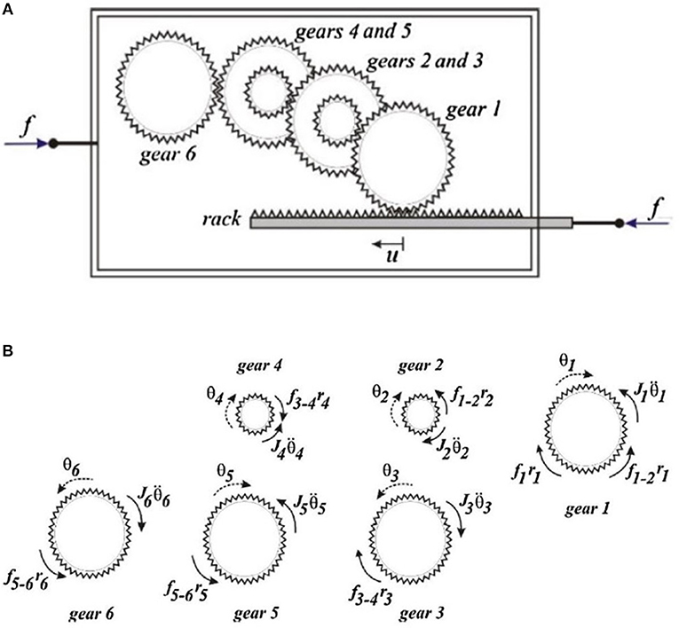
Figure 1. (A) schematic representation of a GMD, (B) free body diagrams of individual gears in the GMD system (Hessabi, 2017).
The restoring force for the screw jack system is shown below:
where mgi corresponds to the mass of the ith gear, N2 = r3/r2 and N3 = r5/r4 are the gear ratios for the compound gears 2 and 3 respectively (calculated as the ratio of the number of teeth of gear 5 and gear 4 for compound gear 3), and b is the equivalent mass of the GMD device. Previous research by Hessabi et al. has demonstrated that GMDs can be quite effective as passive damping devices (Hessabi and Mercan, 2016)—depending on the type of configuration and the type of loading, the reduction in structural displacement can be as high as 60% (GMD in conjunction with non-linear viscous damper). Further details and investigations can be found in relevant literature (Hessabi, 2017).
GMDs and other similar rotational inertia devices are effective and feasible because a device with small form factor is able to have a significant effect on structural performance by capitalizing on gear ratios. In the example shown in Figure 1 with two compound gears, a gear ratio of 5:1 can result in an equivalent inertial force 1,302 times larger than a traditional damping device with the same mass (Hessabi and Mercan, 2016). Furthermore, with a device such as the GMD, the properties of the device can easily be adjusted in order to be tuned to the structure in question by changing the relative gear ratios and masses (Hessabi, 2017).
Screw Jack Device
A screw jack is a type of jack which is operated by turning a screw gear—these devices are often used to lift heavy machinery such as vehicles in auto repair shops. The rotational movement of the input shaft is converted to translational motion and axial force via a worm gear mechanism (Nook Industries, 2016). The screw jack used for this research project is a worm gear trapezoidal screw jack manufactured by Nook Industries.
Whereas, hydraulic jacks and other actuators are power intensive, requiring large amounts of energy and power for oil pumps (Society of Manufacturing Engineers, 1984), the screw jack-based control device developed is able to operate using a battery and servomotor—this makes the system a strong candidate for earthquake response of structures, as the device is able to operate regardless of power failures.
The application of the screw jack for active control of structures is an extension of previous research into the effectiveness of rotational inertia dampers for passive control, as the role of the inertia gear mechanisms is common to both systems (Hessabi and Mercan, 2016).
Methodology
Linear Quadratic Gaussian Controller
Linear quadratic gaussian (LQG) controllers are often used in active control across different control applications (Gawronski, 2004)—they are concerned with linear systems subjected to gaussian noise, undergoing control with quadratic costs. The typical LQG is comprised of two components: a linear quadratic regular (LQR) and a linear quadratic estimator (LQE) such as a Kalman filter (Gawronski, 2004). The LQG control system is made up of the structure G and the controller K–the structure output y is measured and fed to the controller, which outputs the required control force u. A schematic showing the inner structure of the LQG controller can be found in Figure S1, and further details can be found in relevant literature (Gawronski, 2004).
The control force u is calculated as function of the system's estimated state , where Kc represents the controller gain. The system's estimated state is determined from the Kalman filter, as it is not feasible to directly measure the entire system state x for most systems. The structure can be defined by the following state space model:
where the structure's state variable is x, the random noise is v and the controller output is corrupted by noise w. The estimator equations can be obtained:
Before determining the estimated state, the estimator gain Ke must be solved for:
The controller gain Kc and estimator gain Ke are unknown quantities which can be solved for by minimizing the cost function J:
The selection of the weighting matrices Q and R is the subject of much debate, with many different options available. In his book, Murray recommends using diagonal weighting matrices where the individual diagonal elements represent the amount by which each state and input (squared) affect the overall system cost (Murray, 2008)—the individual elements can be selected by weighting the errors of the individual terms. For the weighting matrices Q with diagonal elements qiqn and R with diagonal elements ρiρn, the following methodology is recommended: (1) choose qi and qj as the inverse of the square of the maximum value for the corresponding xi or uj; (2) modify the elements to obtain a suitable solution which factors in time, damping, and control effort, to be done by trial and error (Murray, 2008).
LQG Controller Implementation
Figure 2 shows a single-degree-of-freedom (SDOF) chevron-braced structure equipped with screw jack and viscous damping element. The combination of screw jack and viscous damper was selected in order to build on previous research done by Hessabi et al., which found that the combination of a GMD and viscous damper was significantly more effective than a standalone GMD implementation (Hessabi and Mercan, 2016).
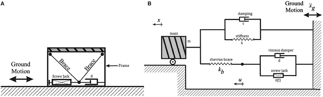
Figure 2. (A) Schematic representation of screw jack-SDOF braced system, and (B) mechanical representation of the system.
A state space model of the chevron-braced SDOF system was developed in order to formulate the LQG controller equations:
where m is the mass of the structure, c is the inherent damping, k is the stiffness of the structure, kb is the stiffness of the chevron brace, d is the damping coefficient for the viscous damping element, p(t) is the dynamic loading applied to the structure (e.g., earthquake load) and s(t) is the screw jack forcing function. The following state variable can then be defined for simplicity:
Combining Equations (8, 9), and using matrix form, the following system equations can be written:
Using the state variable Z(t), Equation (11) can be re-written as the state equation of the system:
Controller Design
In order to execute the control algorithm in real-time, the user re-configurable computational control platform was adapted from previous work (Ashasi-Sorkhabi and Mercan, 2014). The National Instruments NI PXI 8110 controller with onboard 2.26 GHz quad-core processor, equipped with NI PXI 7842R multifunction reconfigurable input-output (RIO) and embedded field-programmable gate array (FPGA) residing on NI PXI 1042 chassis are the key components of the testing platform. Further details regarding the design and layout of the testing platform along with the software development of the platform can be found in the previous work by the 2nd and 3rd authors of this manuscript (Ashasi-Sorkhabi and Mercan, 2014).
Experimental Setup
The setup used to conduct the experiments was comprised of the following: an Emerson XV-6011 servomotor (shown) and Digitax ST base drive (not shown) were used to excite the screw jack. The screw jack's rated 1.27 N·m, with a peak torque of 3.65 N·m–this was amplified through the use of a planetary gearhead with gear ratio 5:1. The gearhead was then mounted to the screw jack input shaft using a custom-machine mounting flange, and off-the-shelf shaft coupling mechanism. The lift shaft of the screw jack was in turn connected to a 22.2 kN (5,000 lbs) rated load cell to measure the screw jack's force output. An image of the experimental setup can be seen in Figure S2.
Screw Jack Characterization
Since this research project was the first application of the screw jack in a dynamic load setting, it was necessary to first understand the behavior of the device in a dynamic environment. A series of tests were done to this end, consisting of step load as well as time-varying square wave inputs to the screw jack device. The step load scenario was done in order to get an understanding of how quickly the device is able to achieve the required force level (rise/settling time), while the square wave tests were done in order to understand the frequency-based response of the system and determine a frequency limit for the screw jack device. Six tests were performed for the step response of the system, with force amplitudes of 15, 25, 35, 60, 70, and 80% of the screw jack's maximum force. Similarly, for the square wave characterization tests, four loading magnitudes of 10, 25, 40, and 50% were used at each frequency tested. Six frequency levels were tested-−0.17, 0.25, 0.5, 0.67, 1.0, and 2.0 Hz.
Upon completion of the characterization tests, the data was analyzed and used to determine a suitable system transfer function for the screw jack device. This transfer function, which would mathematically map the screw jack input-output relationship, can then be evaluated against test data and used to predict the experimental behavior of the screw jack device in unknown loading scenarios.
Numerical Simulation
This section of the paper discusses the methodology for various types of numerical simulations which were performed in order to understand the performance of a structure equipped with screw jack and viscous damping element. A parametric investigation was carried out in order to optimize the structural performance while minimizing control effort.
For the purposes of the numerical simulations, a Simulink model was built to solve the system of equations of the system under dynamic loading (historical earthquake records). At each simulation time step, the system state (including acceleration, velocity, displacement) are fed to the LQG algorithm, simulating the output of an accelerometer placed on the structure. The output of the LQG algorithm is in turn fed to the model to be directly used as the screw jack force for the next time step. The system transfer function was not used in the numerical simulations, as it was determined to have a frequency limit (and frequency of the LQG output force is not known a priori).
Selection of Ground Motion Records
A set of seven ground motion records were chosen for use in the numerical simulations, selected from the Pacific Earthquake Engineering Research Center (PEER) ground motion database (Pacific Earthquake Engineering Research Center, 2017). The selected records were scaled to match the Vancouver design spectrum as per the National Building Code of Canada—the list of records can be found in Table S1.
Control Effort Parametric Investigation
Recall that the LQG controller is designed to minimize the following cost function J:
The quadratic cost function is comprised of two parts—one which penalizes the structural response x (weighted by the matrix Q), and one which penalizes the required control effort u (weighted by the matrix R). By modifying the relative elements within these two matrices, the controller can be fine-tuned to place more emphasis on reducing structural response at the expense of a higher control cost, or vice versa. With this trade-off in mind, four scenarios were conceived—each case corresponded to varying levels of cost for both control effort and structural response. A summary of the four scenarios can be found in Table S2.
In the optimal case, the structural response is highly penalized with no regard for the required control effort. This corresponds to optimal structural response during dynamic loading but is not necessarily a feasible and realistic target for a real device with physical limitations. This is used as an ideal theoretical scenario for the purposes of comparison. Case 1, 2, and 3 correspond to more realistic scenarios, with each scenario penalizing the structural response more heavily than the last. Case 3 corresponds to a medium cost placed on control effort, and a low cost placed on the structural response. These three more realistic scenarios were selected in order to match the screw jack system as it was characterized, especially considering the frequency limitations as described further in section System Transfer Function. Case 3 was selected to match the open loop screw jack system as characterized, due to the high delay observed in the system. Case 2 and Case 1 were selected with more cost associated with structural performance, and less cost on the required control effort—in this way, these two scenarios demonstrate the additional benefits to be gained from making improvements to the screw jack control system being implemented, such as using closed-loop control or a more frequency-responsive actuator.
For the purposes of this investigation, the main structural parameter of interest which was chosen to be minimized is the structural displacement. Hence, weighting matrices for the LQG controller were imposed to penalize the structural response, with a particular emphasis on the terms corresponding to the structural displacement cost (rather than structural velocity or acceleration). However, the strength of the LQG algorithm lies in its flexibility—if for another implementation the main structural parameter to minimize was structural acceleration, the LQG controller could easily be tuned to reflect this by modifying the weighting matrices Q and R.
Loop Simulation Tests
The setup required for the loop simulation method (LSM) consisted of the screw jack device, servomotor and drive, the user-reconfigurable computational control platform described in section Controller Design, and a force transducer (load cell). More information on the experimental setup can be found in relevant literature (Ashasi-Sorkhabi, 2015). In LSM, the analytical substructure was compiled from a Simulink model as a DLL file and simulated in LabView. For each time step, the structural response was calculated for the given loading level, and the system state was fed to the LQG algorithm. The required force level (output of LQG model) was converted to a corresponding voltage command for the servomotor, which activated the screw jack's worm gear mechanism. The force level as measured by the load cell was fed back to the digital controller for logging, and was further used by the controller in the next time step. At the next time step, a new force requirement was calculated (considering the variation between commanded and measured force in the previous time step), and the process repeated itself.
The LSM method was set to match Scenario 1 from the parametric investigation previously mentioned, which corresponded to a high cost for the required control effort. This was used as it was deemed to be the most realistic for implementation using the screw jack device, considering the physical and frequency-based constraints of the device.
Results
This section of the paper discusses the results from the various types of tests which were performed on the device, including characterization tests, development of the system transfer function, numerical simulation tests and parametric investigations, and results from the loop simulation method tests.
Screw Jack Characterization Results
As mentioned previously in the paper, both step function loading scenarios as well as square wave loading scenarios were used to characterize the dynamic performance of the screw jack device.
Figure 3 summarizes the results from the step load characterization tests, and Table S3 summarizes the rise time and settling time for the various testing levels. Using a linear relationship between the system's voltage-to-force relationship, the screw jack is accurately and precisely able to develop the level of force commanded, which confirms that the linear voltage-to-force relationship. This confirms that in a static loading scenario, the screw jack system can be accurately controlled to develop a resisting force using one command signal without the need to close the loop and adjust for errors.
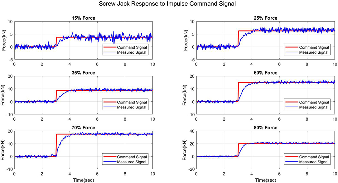
Figure 3. Screw jack characterization tests: step force command vs. measured force.
A second observation which can be made is that the rise time (defined as the time taken for the signal to go from 10 to 90% of its steady value) and settling time (defined as the time taken for the signal to stabilize within ±5% of its steady value) for the screw jack system is significant, as confirmed in the data in Table S3. This is due to the high rotational inertia of the worm gear mechanism of the screw jack—while the servomotor is able to operate at a maximum speed of 5,000 RPM, there is a 120:1 compound gear ratio between the motor and the screw jack input shaft. The input shaft must rotate in order to engage the worm gear, which in turn must rotate in order to apply the required force to the load cell via the lift shaft of the screw jack. Table S3 shows that there is a greater rise time for the lower force levels than for the higher force levels—it was observed that for the higher force levels, the motor operated at a higher speed, resulting in the required force level being developed more quickly.
Figures 4, 5 show two results from the square load characterization tests which were performed—further results from these tests can be found in the Supplementary Material (Figures S3, S4). Similar to the results from the step loading scenario, a significant rise time is observed for the smaller force levels, meaning that the desired force is only achieved at the end of the loading cycle. At the lower loading frequencies (Figure 4, Figures S3, S4), the delay is reduced at the higher loading levels—this was again due to the observed higher motor speed for the higher force levels.
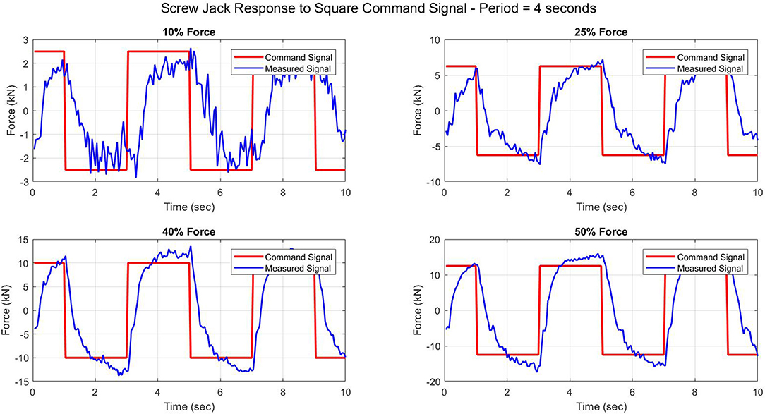
Figure 4. Screw jack characterization tests: square wave force command, period = 4.0 s.
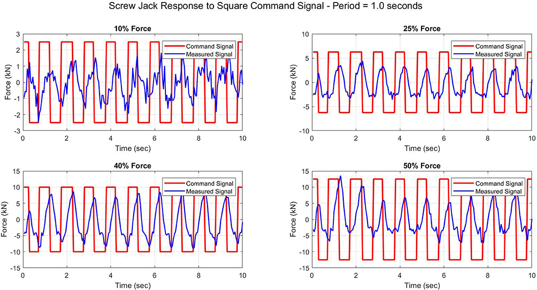
Figure 5. Screw jack characterization tests: square wave force command, period = 1.0 s.
At the higher loading frequencies (Figure 5, Figures S5, S6), the characterization tests tell a different tale. The results show that regardless of the commanded force level, the frequency of the command signal is too high for the screw jack device. The rise time of the screw jack device is greater than the half-period of the command signal, and hence the device is not able to fully develop the required force.
The results from the square wave command signal tests, both at lower and higher frequencies, indicate that there is a maximum frequency at which the screw jack can be excited—anything past this frequency limit, and the screw jack does not fully develop the required force. This is because of the mechanism of the screw jack—since the lift shaft of the device develops force based on the rotation of the built-in worm gear mechanism, the high inertia of the gear mechanism is the limiting factor for the screw jack. Therefore, applications of the screw jack device should be mindful of the physical limitations of the device and the corresponding frequency limit. The relationship between force commanded and frequency should also be considered, as the rise time for the screw jack device is dependent on the level of force commanded to the system.
System Transfer Function
A mathematical representation of the system which maps the system's input-output relationship, called a transfer function, was developed from the characterization test data. The system identification for the screw jack was carried out using Matlab's System Identification app and related toolboxes, which can be seen in the Supplementary Material (Figure S7) (The MathWorks Inc., 2013). Individual transfer functions were determined for each characterization test (30 tests total) by mapping each individual input-output relationship, yielding 30 individual transfer functions, in order to develop a baseline for comparison with the overall system transfer function. The overall system transfer function was obtained by mapping all 30 input-output relationships into a single transfer function. Both individual transfer function results and overall transfer function results are compared with experimental data, which is summarized in Table S4.
From these results, a few conclusions can be drawn regarding the performance of the overall system transfer function. The first is that at low force amplitudes, the transfer function does not perform as well as for the high force amplitude tests. This is likely due to the measurement error in the load cell, which constitutes a larger percentage of the measurement at low force levels when compared with higher force levels. However, this poor performance is also a function of the relationship between motor force and screw jack force. The response of the screw jack at low force levels was observed and measured to be more erratic than at higher force levels. This is because of the minimum level of torque required to engage the screw jack's gear mechanism (called starting torque). Even though the load capacity of the screw jack is rated at 25 kN, this does not mean that the system is able to equally apply any level of force that falls below 25 kN. The screw jack is more unpredictable at lower force levels, and therefore the system behavior is harder to capture with a standard mathematical model such as a system transfer function.
A second observation which can be made from the determination of the system transfer function is that its performance is dependent on the frequency of the command force signal. It was observed that the transfer function does not accurately capture the behavior of the screw jack device for high frequency command signals. This is likely because the screw jack performance was poor at these high frequencies, and hence its behavior was erratic and difficult to model. This can be seen by comparing the results shown in Figures S8, S9 with those in Figure S10.
The poor force tracking which was observed for the screw jack device coupled with the poor performance of the system transfer function at high frequencies suggest that there is a frequency limit both to which the screw jack can operate as well as be modeled mathematically. Therefore, any further implementations of the screw jack device and the accompanying transfer function should take the frequency limit into consideration, which was determined to be 0.667 Hz for the screw jack device and 0.5 Hz for the system transfer function.
Numerical Simulation and Parametric Investigation Results
This section presents the results of the various numerical simulations which were performed on a screw-jack controlled SDOF structure subjected to various ground motion records (summarized in Table 1). This section also shows the results of the parametric investigation of the LQG controller, in which the relative costs associated with structural control and controller effort were investigated and optimized for the screw jack device. The SDOF structure was modeled with a structural mass of 10,000 kg, a period of 1.1 s, an inherent damping ratio of 2%, as well as a chevron brace stiffness of 66.3 kN/m and a viscous damping coefficient of 930 Ns/m.
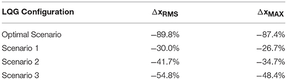
Table 1. Summary of mean improvements to structural performance during LQG controller parametric investigation.
Figures 6, 7 show the structural displacement history, as well as required control force from the screw jack device in the optimal screw jack scenario for a SDOF structure subjected ground motion record # 746. The results show that the improvement in structural performance is quite drastic, and an 88% reduction in RMS structural displacement is observed. However, as shown in Figure 7, the force history required to achieve this level of structural performance would require an actuator with exquisite and precise force tracking. This is because for the optimal scenario, structural performance was highly penalized in the LQG controller while control effort was penalized much less. Similar tests were performed for the LQG control algorithms while tweaking the relative cost placed on structural performance and control effort required (scenario 1, scenario 2, scenario 3). A summary of the costs associated with these different scenarios is shown in Table S2.
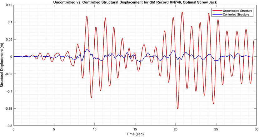
Figure 6. Structural displacement of SDOF structure subjected to ground motion record no. 746 with and without screw jack (optimal scenario), calculated using numerical methods.
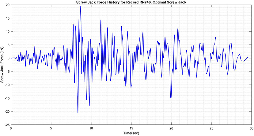
Figure 7. Screw jack force history required for control of SDOF structure subjected to ground motion record no. 746 (optimal scenario).
A similar set of tests were performed for all 4 LQG configurations, and a summary of the benefits to structural performance parameters is shown in Table 1. Scenario 3 showed the next most significant improvement in structural performance (Figure S13), however the control force that was required to achieve this was not feasible for the screw jack device (Figure S14). Similarly, Scenario 2 also had significant improvement in structural performance (Figure S11) but suffered the same shortcomings with regards to required control force (Figure S12).
The scenario which was deemed to be most feasible for implementation in the screw jack device was Scenario 1, in which structural performance was penalized much less than the required control effort. While the improvement in structural performance is lower than for the optimal scenario (both for RMS displacement and peak displacement) as can be seen in Figure 8, the control force required is within the limits of the screw jack system, as can be seen in Figure 9. Despite the smaller benefit to structural performance when compared with the optimal scenario, or even compared with Scenario 2 or Scenario 3 (summarized in Table 1), the improvement in structural performance in Scenario 1 is by no means negligible. Peak structural displacements are reduced by 26.7% when compared with the uncontrolled structure, and RMS displacements are similarly reduced by 30.0%. The results of the parametric study for all scenarios, considering all structural parameters of interest (compared to the uncontrolled SDOF structure) are shown in Figure 10.
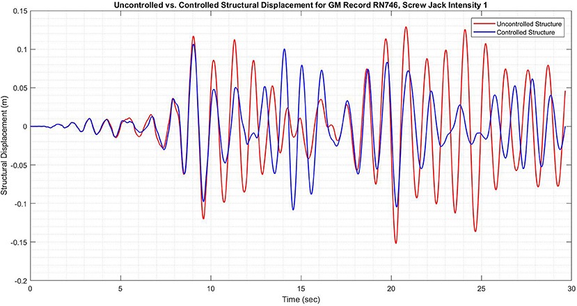
Figure 8. Structural displacement of SDOF structure subjected to ground motion record no. 746 with and without screw jack (scenario 1), calculated using numerical methods.
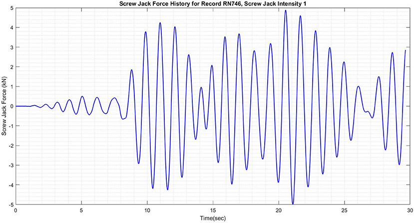
Figure 9. Screw jack force history required for control of SDOF structure subjected to ground motion record no. 746 (scenario 1).
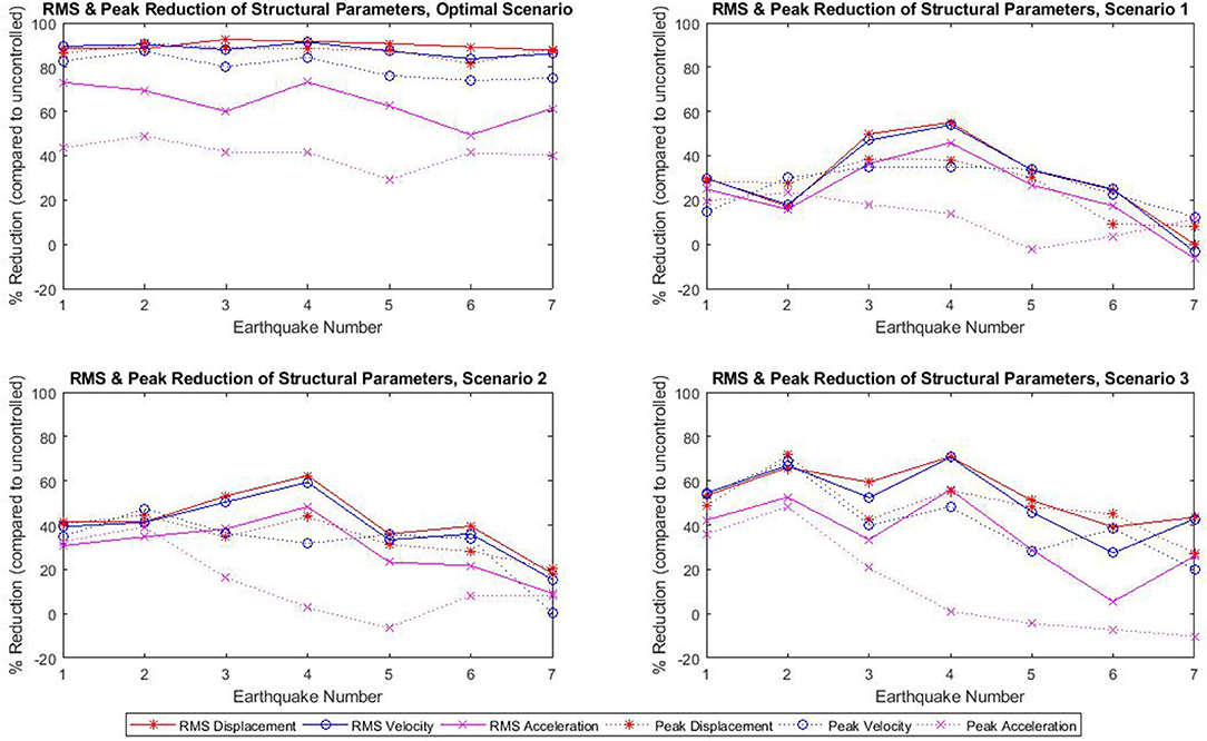
Figure 10. Results for all four scenarios showing reductions to key structural parameters (obtained through numerical simulation).
Upon completion of the parametric study (Noormohamed, 2018), it was determined that the most realistic scenario for implementation in an experimental study was Scenario 1. As previously mentioned, this was due to the physical frequency-based force tracking constraints of the device as highlighted earlier in the paper. Therefore, for further experimental results, the LQG control algorithm was configured using the weighting functions corresponding to Scenario 1, which placed a high cost on control effort and a low cost on the structural performance.
Loop Simulation Method Results
Figure 14 summarizes the structural performance for the same set of ground motion records as used in the numerical simulations. The results indicate that the loop simulation method (LSM) experimental results yielded less favorable results than the numerical simulations. In particular, record 975 was the only one in which the screw jack improved RMS structural displacement while records 975 and 3,859 were the only ones to see an improvement in peak structural response. On average, the change in RMS structural response was an increase in 39.3% while the change in peak structural response was an increase of 11.1%. Figure 14 indicates that the results for peak structural response (displacement, velocity, acceleration) are more favorable than the RMS response, although both performed worse than the uncontrolled SDOF structure as per the numerical simulations.
In Figure 11, the screw jack is observed to slightly reduce the structural displacement, with a reduction of 10.2% in the RMS structural displacement and a reduction of 5.8% in the peak structural displacement. It can be seen in Figure 13 that the commanded force is not developed by the screw jack—this is due to the relatively high rise time of the system compared with the force history required by the LQG controller. Nonetheless, the reduction in structural displacement in Figure 11 is in sharp contrast with the results shown in Figure 12, which indicate an increase in RMS structural displacement of 195.4% and an increase in peak structural displacement of 69.2%.
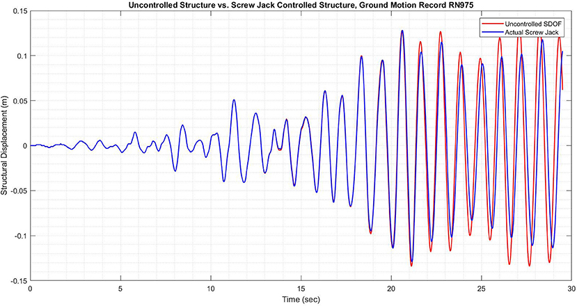
Figure 11. Results of LSM showing structural displacement with and without screw jack for record 975.
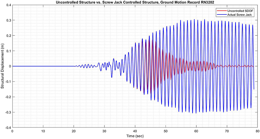
Figure 12. Results of LSM showing structural displacement with and without screw jack for record 3,202.
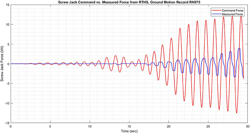
Figure 13. Command screw jack force vs. measured force for record 975.
The results in Figure 12 are a result of the high lag in the screw jack system—as the structural response increased, the restoring force calculated by the LQG control algorithm increased accordingly—however, due to the high inertia and lag inherent in the screw jack, the force was applied with significant delay. In the case of record 3202, this delay in force application caused a significant increase in both RMS and peak structural performance. While this did not occur for any of the other ground motion records which were tested, it indicates the potential for the screw jack to adversely affect structural performance due to the delay between command and actual force. The results from all seven ground motion records (simulated using the loop simulation method) can be found below in Figure 14. These results, while not as positive as in the numerical simulations, indicate that the screw jack can be effective in reducing the peak structural parameters, which correlate to the level of damage that the structure sustains under dynamic loading.
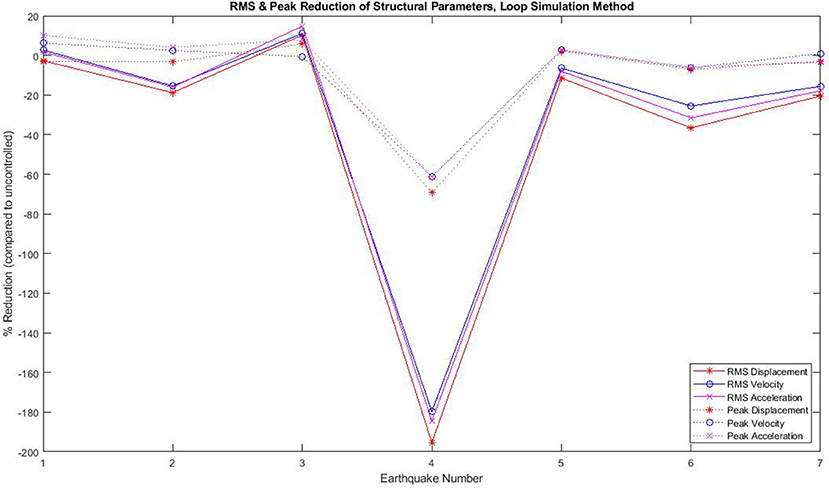
Figure 14. Results for all ground motion records showing reductions to key structural parameters (obtained through loop simulation method).
Discussion
The frequency limitations of the screw jack device were quite apparent throughout the investigation of the device, especially when looking at the loop simulation method results. Despite a frequency limit having been established in the course of the device characterization tests, it was found that the irregularity of the force command signal in a real application (with a ground motion record used to excite the SDOF structure) proved too erratic for the screw jack device. Not only was the screw jack experimentally determined not to provide much benefit to a SDOF structure, but in many cases it was found to be detrimental to structural performance.
The frequency limitations of the device imply that its use should be limited to certain specific scenarios, upon further investigations. In particular, its use should be confined to flexible structures with high periods, whose displacements during earthquakes would require control forces more in line with the capabilities of the screw jack device. This would entail limiting the implementations of the screw jack to systems which oscillate slowly, as this would be the scenario in which the screw jack would be best able to provide benefit.
With this in mind, the screw jack system has the potential to work well if coupled with other structural control techniques, in particular those which have the effect of lengthening the period of vibration of a structure, de-coupling the structure from the ground vibrations. Two such structural control techniques are base isolation systems and gyro-mass damper systems. Both of these techniques serve to increase the period of vibration of a structure, either by decreasing the apparent stiffness (in the case of base isolation systems) or by increasing the apparent mass (in the case of the gyro-mass dampers). While the combination of the screw jack device with these systems was not investigated in this research project, this is an area of future work which has the potential to broaden the scope of applicability of the screw jack system when compared with the standalone system investigated in this research project.
Furthermore, implementation of a system such as the screw jack is also dependent on the nature of the excitation to the structure in question. The screw jack was found to perform differently when the same structure was subjected to near-field ground motion records when compared with far-field ground motion records, as these two types of records excite the same structures differently. Soil and rock conditions at the site of a structure are also important considerations, as the attenuation of ground motions is highly dependent on the types of soil upon which structures are built.
Conclusion and Future Work
This paper presented an original research project in which a standard, off-the-shelf screw jack device was characterized and tested in a structural engineering application. The screw jack was first characterized and modeled using a transfer function for use in numerical simulations—both the screw jack and the transfer function were found to have frequency restrictions which limit their applications to low-frequency systems. Numerical simulations and a parametric study on the LQG control algorithm were conducted in order to determine a controller configuration in line with the physical limitations of the device—a configuration which placed a high penalty on required control effort was found to be most realistic. This LQG configuration was then implemented in experimental loop simulation method tests using a set of seven ground motion records. The high inertia of the system combined with the high frequency force command signal resulted in the screw jack negatively affecting structural performance overall, with a few exceptions.
Future work on the screw jack should be focused on a few key areas—the first of these is further characterization of the screw jack device using various types of input signals, and development of a more robust system transfer function. Secondly, future work should focus on understanding and characterizing the soil conditions and structure characteristics for which the screw jack is able to best improve structural performance. Lastly, further experimental investigations of the screw jack device should be done using closed-loop control in real-time hybrid simulation experiments, allowing for better force tracking and further improvements to structural performance.
Author Contributions
The authors declare that the research was conducted by AN under the supervision of OM. Assistance was provided by AA-S in the execution of the testing of the device, especially with regards to the experimental system design and programming for the loop simulation method experiments.
Funding
This paper is based upon work funded by the Natural Sciences and Engineering Research Council of Canada (NSERC) Discovery (201606290) Program.
Conflict of Interest Statement
The authors declare that the research was conducted in the absence of any commercial or financial relationships that could be construed as a potential conflict of interest.
Acknowledgments
The authors would like to acknowledge the assistance of Dr. Reza Hessabi, who assisted in various aspects of the research projects. The authors would further like to acknowledge Dr. Oh-Sung Kwon, who provided equipment for use in the experiments.
Supplementary Material
The Supplementary Material for this article can be found online at: https://www.frontiersin.org/articles/10.3389/fbuil.2019.00043/full#supplementary-material
References
Ashasi-Sorkhabi, A. (2015). Implementation, Verification, and Application of Real-Time Hybrid Simulation. PhD Thesis, University of Toronto.
Ashasi-Sorkhabi, A., and Mercan, O. (2014). Development, implementation, and verification of a user configurable platform for real-time hybrid simulation. Smart Struct. Syst. 14, 1151–1172. doi: 10.12989/sss.2014.14.6.1151
Gawronski, W. (2004). Advanced Structural Dynamics and Active Control of Structures. New York, NY: Springer-Verlag. doi: 10.1007/978-0-387-72133-0
Hessabi, RM. (2017). Application of Real-Time Hybrid Simulation Method in Experimental Identification of Gyromass Dampers. PhD Thesis, University of Toronto.
Hessabi, R. M., and Mercan, O. (2016). Investigations of the application of gyro-mass dampers with various types of supplemental dampers for vibration control of building structures. Eng. Struct. 126, 174–186. doi: 10.1016/j.engstruct.2016.07.045
Ikago, K., Inoue, N., and Saito, K. (2012). Seismic control of single-degree-of-freedom stucture using tuned viscous mass damper. Earthquake Eng. Struct. Dynam. 41, 453–474. doi: 10.1002/eqe.1138
Jafarzadeh, R., Ingham, J., and Wilkinson, S. (2014). A seismic retrofit cost database for buildings with a framed structure. Earthquake Spectra 30, 625–637. doi: 10.1193/080713EQS226
Nook Industries. (2016). Metric Upright Translating Machine Screw Jacks Available online at: http://www.nookindustries.com/Product/ProductName/101667/ActionJac%20EM2.5-MSJ-U%2024:1 (Accessed on January 1, 2016).
Noormohamed, A. (2018). Optimal Active Control of Structures Using a Screw Jack Device and Linear Quadratic Gaussian Controller. MASc Thesis, University of Toronto.
Pacific Earthquake Engineering Research Center (2017). PEER Ground Motion Database. Available online at: https://ngawest2.berkeley.edu/ (accessed on October 1, 2017).
Society of Manufacturing Engineers. (1984). Hydraulic Accessories: Power Workholding Pumps, Motors, Actuators, and Drives, Cylinders, Valves, Boosters, and Intensifiers, Gauges, Hoses, Fittings. Dearborn, MI: Society of Manufacturing Engineers, Publications Development Dept.
Keywords: active control, linear quadratic gaussian, screw jack, structural control, earthquake engineering, vibration control
Citation: Noormohamed A, Mercan O and Ashasi-Sorkhabi A (2019) Optimal Active Control of Structures Using a Screw Jack Device and Open-Loop Linear Quadratic Gaussian Controller. Front. Built Environ. 5:43. doi: 10.3389/fbuil.2019.00043
Received: 12 December 2018; Accepted: 14 March 2019;
Published: 12 April 2019.
Edited by:
Ersin Aydin, Niǧde Ömer Halisdemir University, TurkeyReviewed by:
Aleksandra Bogdanovic, Institute of Earthquake Engineering and Engineering Seismology, MacedoniaKohei Fujita, Kyoto University, Japan
Sara Casciati, Università degli Studi di Catania, Italy
Copyright © 2019 Noormohamed, Mercan and Ashasi-Sorkhabi. This is an open-access article distributed under the terms of the Creative Commons Attribution License (CC BY). The use, distribution or reproduction in other forums is permitted, provided the original author(s) and the copyright owner(s) are credited and that the original publication in this journal is cited, in accordance with accepted academic practice. No use, distribution or reproduction is permitted which does not comply with these terms.
*Correspondence: Ali Noormohamed, YWxpLm5vb3Jtb2hhbWVkQGFsdW0udXRvcm9udG8uY2E=