 Eva O. L. Lantsoght
 Yuguang Yang2
- 1Politécnico, Universidad San Francisco de Quito, Quito, Ecuador
- 2Concrete Structures, Department of Engineering Structures, Civil Engineering and Geosciences, Delft University of Technology, Delft, Netherlands
- 3Ane de Boer Consultancy, Arnhem, Netherlands
Existing bridges with large uncertainties can be assessed with a proof load test. In a proof load test, a load representative of the factored live load is applied to the bridge at the critical position. If the bridge can carry this load without distress, the proof load test shows experimentally that the bridge fulfills the requirements of the code. Because large loads are applied during proof load tests, the structure or element that is tested needs to be carefully monitored during the test. The monitored structural responses are interpreted in terms of stop criteria. Existing stop criteria for flexure in reinforced concrete can be extended with theoretical considerations. These proposed stop criteria are then verified with experimental results: reinforced concrete beams failing in flexure and tested in the laboratory, a collapse test on an existing reinforced concrete slab bridge that reached flexural distress, and the pilot proof load tests that were carried out in the Netherlands and in which no distress was observed. The tests in which failure was obtained are used to evaluate the margin of safety provided by the proposed stop criteria. The available pilot proof load tests are analyzed to see if the proposed stop criteria are not overly conservative. The result of this comparison is that the stop criteria are never exceeded. Therefore, the proposed stop criteria can be used for proof load tests for the failure mode of bending moment in reinforced concrete structures.
Introduction
Proof load testing is a method of assessment that can be particularly interesting for structures with large uncertainties (Lantsoght et al., 2017g). These uncertainties can be related to the (lack of) information available about the structure (Aguilar et al., 2015), to the effect of deterioration on the structural capacity (Lantsoght et al., 2017b), and to the overall structural behavior at load levels beyond the serviceability state (Faber et al., 2000). In a proof load test, a load representative of the factored live load, the so-called target proof load, is applied to the bridge at the critical position. For the target proof load to be equivalent to the factored live load or the considered factored load combination, the target load is determined for which the sectional moment or shear is the same as for the factored live load or the considered factored load combination (Halicka et al., 2018). The proof load should be applied at the critical position, which currently is assumed to be the position that results in the largest load effect (Chen et al., 2018). For bridges with a variable height or changing reinforcement layout, the position with the largest Unity Check (factored load effect divided by factored capacity) can be different from the position that results in the largest load effect. In some cases, however the reinforcement layout is not known, which complicates using the Unity Check for determining the critical position. If the bridge can carry the target load without distress, the proof load test is successful. The test then shows experimentally that the bridge fulfills the requirements of the code with regard to strength. If distress occurs prior to reaching the target proof load, the proof load test must be terminated and further loading is not permitted. In this case, the structure may still be used for lower load levels, depending on the largest load the structure could carry without signs of distress. In some cases, the load is increased further after reaching the target proof load to study the load at which non-linearity and distress occur. This application is not part of standard proof load testing protocols but may be interesting for research applications or to study the behavior of certain bridge types (Schmidt et al., 2018).
Because proof load tests require large loads, the structure or element that is tested needs to be carefully monitored during the test. Monitoring the structural responses is important for the safety of the executing personnel and, for bridges, for the traveling public in the vicinity of the tested bridge. The monitored structural responses are interpreted in terms of stop criteria. If a stop criterion is exceeded, an indication is given that further loading can result in irreversible damage or failure. If a stop criterion is exceeded before reaching the target proof load, no further loading is permitted and the conclusion is that the structure does not fulfill the code requirements for the factored load combination that corresponds to the target proof load. Figure 1 shows this approach and the safety philosophy for proof load testing: the target load is Ftarget, and the load that needs to be applied in addition to the available permanent load G1 is ext.Ftarget. The load ext.Ftarget should be representative of the additional permanent loads not present at the time of load testing, Gdj, and the live loads Qd. The load at which a stop criterion is reached is Flim and this load relative to the present permanent loads is ext.Flim, with Flim—G1 = ext.Flim. The load level at which the sectional capacity of the structure is reached is effRu. There are two possible outcomes of a proof load test, illustrated in Figure 1. If ext.Ftarget is smaller than or equal to ext.Flim, then the target proof load can be applied before reaching the onset of non-linear behavior, and the proof load test is considered successful (First case in Figure 1). The bridge has then been shown to be able to carry the code-prescribed loads. The second possible outcome is that ext.Ftarget is larger than ext.Flim: the bridge exhibits non-linear behavior before the full target proof load is applied. The full target proof load can then not be applied. Further loading past the onset of non-linearity is not allowed, as it can result in permanent damage or collapse. Depending on the largest load level that was reached during such a proof load test, the conclusion may still be that the bridge fulfills the code requirements for reduced live load, that a traffic restriction should be imposed, or that load posting should be installed.
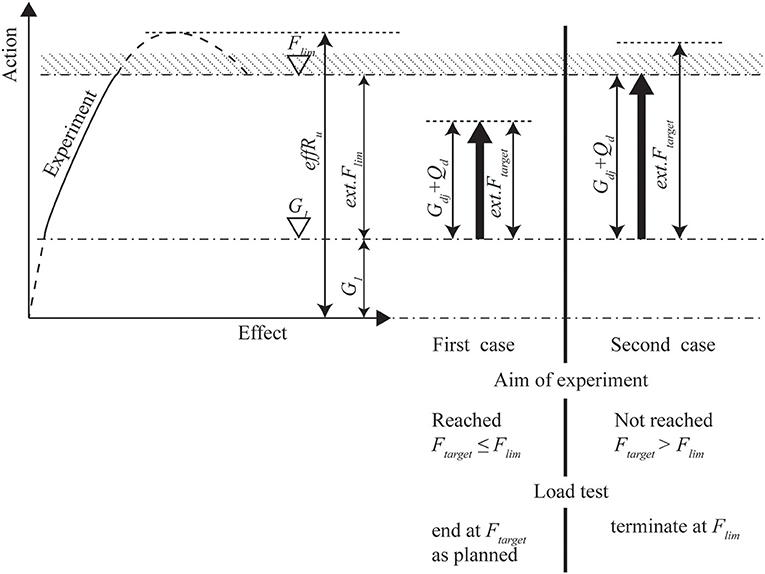
Figure 1. Philosophy of load testing as given in German guideline (Deutscher Ausschuss für Stahlbeton, 2000). Figure reprinted from Lantsoght et al. (2017g) with permission.
Proof load testing can be used for new bridges and for the assessment of existing bridges. For new bridges, proof load testing was more common in the past, when a proof load test demonstrated to the traveling public that a new bridge was safe for use. Nowadays, with better analytical tools for the design of bridges, there is less of a need for such demonstrations. Where load tests are required prior to opening a new bridge, diagnostic load tests are often sufficient (Bonifaz et al., 2018). For existing bridges, proof load tests are a valuable method for the assessment when analytical methods cannot be used or are insufficient (Lantsoght et al., 2017a).
Since proof load tests involve the use of high load levels, monitoring the structural response is important to guarantee the structural safety as well as the safety of personnel on site and the traveling public. This paper focuses on stop criteria for flexure. Such stop criteria exist, but we show that improvements based on the cross-sectional analysis and principles of concrete cracking can be proposed to have a more solid basis. The proposed theoretically-derived stop criteria are then compared to results from laboratory tests to check the margin of safety, and to results from field tests to check if the proposed criteria are not overly conservative.
Stop Criteria in Existing Codes and Guidelines
German Guideline
In Germany, guidelines for load testing of concrete structures (Deutscher Ausschuss für Stahlbeton, 2000), mostly aimed at buildings, are available to ensure a safe execution of such tests. The scope of the guidelines is plain and reinforced concrete structures, and the guideline only considers the ductile failure mode of flexure. Testing for shear is not allowed. The German guideline describes detailed stop criteria. The first stop criterion limits the measured concrete strain εc:
The limit is the difference between εc, lim (600 με or maximum 800 με for concrete with a compressive strength larger than 25 MPa) and εc0, the analytically determined short-term strain in the concrete caused by the permanent loads that are acting on the structure before the application of the proof load. The second stop criterion limits the measured strain in the reinforcement steel εs2:
The limit is the difference of 70% of the yield strain of the tension steel, determined by dividing the average yield strength fym of the steel reinforcement on the tension side of the cross-section by the modulus of elasticity of the tension steel Es and the strain εs02, the analytically determined strain in the reinforcement steel caused by the permanent loads acting on the structure before the application of the proof load, assuming that the concrete cross-section is cracked. When the full stress-strain diagram of the steel is known, Equation (2) can be replaced by:
in which f 0.01m is the average value of the stress in the reinforcement steel at a strain of 0.01%, which marks the end of the elastic range of the steel. The reader should note that this stop criterion requires measuring the strains in the reinforcement steel, which practically means removing the concrete cover to instrument the rebar. Most owners will not allow such damage to their structure, so that in practice this stop criterion can seldom be evaluated for bridges.
The third stop criterion limits the crack width w for new cracks, and the increase in crack width Δw for existing cracks. The guideline limits the maximum crack width or increase in crack width during proof loading, as well as the residual crack width after removal of the proof load, see Table 1.
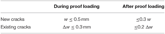
Table 1. Requirements for crack width for newly developing cracks w and increase in crack width for existing cracks Δw (Deutscher Ausschuss für Stahlbeton, 2000).
The fourth stop criterion limits the deflections as monitored with the load-deflection diagram in real-time during the test. In the cracked state, the stop criterion for deflection is either a clear non-linear increase in the deflection or a residual deflection of 10% after removal of the load.
The last stop criteria on limits the strains in the shear span of beams with shear reinforcement. The limiting concrete strain is then 60% of the limit from Equation (1) and the limiting steel strain in the shear reinforcement is then 50% of the limit from Equations (2) or (3), depending on the available material properties.
Czech and Slovak Codes
In the Czech Republic (Ceský normalizační institut, 1996) and Slovakia (Slovak Standardization Institute, 1979), a code is available for diagnostic (static and dynamic) and proof load testing of bridges (Frýba and Pirner, 2001; Kopácik, 2003). These bridges can be reinforced concrete, pre-stressed concrete, or steel. Note that our current work only deals with reinforced concrete, but the provisions from these codes for other building materials have been included to show the more complete scope of these codes. The code describes acceptance criteria, which are verified after a load test to check if the performance was adequate. These criteria do not have as their goal to warn before possible failure or irreversible damage. The first acceptance criterion prescribes the bounds for the ratio of the elastic deformation Se to the calculated value Scal:
Table 2 gives the values for the limits α and β depending on the type of bridge.
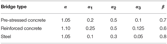
Table 2. Determination of parameters per bridge type (Frýba and Pirner, 2001).
The second acceptance criterion evaluates the ratio of the permanent deformation Sr to the total deformation Stot = Sr + Se:
Table 2 gives the value of α1 as a function of the bridge type. For new bridges, repeated testing can be necessary to meet the acceptance criteria. Equation (5) can then be replaced with
provided that the measured deformations during the first loading fulfill:
Table 2 gives the values of α1, α2, and α3 as a function of the bridge type. If the measurements of the retest do not satisfy (Equation 6), a third test may be necessary, for which the deformation should fulfill:
Table 3 summarizes the limits to the crack width as a function of the environmental class, which form the third acceptance criterion. If the measurements do not fit within the bounds of the acceptance criteria, the Czech and Slovak codes require a special investigation, long-term monitoring, and/or dynamic testing of the bridge.
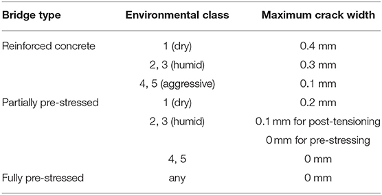
Table 3. Limitations to crack widths that can occur in a load test for reinforced concrete bridges (Frýba and Pirner, 2001).
Spanish Guidelines
In Spain (Ministerio de Fomento - Direccion General de Carreteras, 1999; Ministerio de Fomento, 2009, 2010), load testing of new bridges prior to opening is required. The stop criteria are based on the remanence, αrem:
with fr the remaining measurement and f the total measurement. The stop criterion is related to the maximum remanence αlim, which is 20% for reinforced concrete bridges, 15% for pre-stressed bridges or composite bridges, and 10% for steel bridges. When αrem ≤ αlim the stop criterion is fulfilled. When αlim < αrem ≤ 2αlim, the bridge has to be loaded to the same load level again. If α > 2αlim the stop criterion is exceeded and further loading is not permitted. When a second load cycle is used, the remanence in the second cycle is . The stop criterion then is ≤ αrem/3.
The performance of a new bridge is considered adequate when it fulfills the acceptance criteria. The Spanish guidelines give four acceptance criteria. The first acceptance criterion is that the maximum measured deflection should not be more than a certain percentage of the analytically determined deflection. For pre-stressed and steel bridges, this percentage is 10%, and for composite and reinforced concrete bridges, it is 15%. If the maximum measured deflection is <60% of the analytically determined deflection, the reason for this difference should be found. The second acceptance criterion states that for continuous bridges a simplified test can be used if the results of the simplified test do not differ more than 10% with the full load test. The third acceptance criterion states that the crack widths should not exceed the limits for the serviceability limit state. The last acceptance criterion allows no signs of distress or exhaustion of the structural capacity.
Other Existing Codes and Guidelines
The following codes and guidelines are available that give information about load testing of bridges and that give some guidance in terms of stop or acceptance criteria: the Manual for Bridge Evaluation (AASHTO, 2016), the Swiss code (SIA, 2011), the Polish code (Research Institute of Roads and Bridges, 2008), and the Spanish code for acceptance testing of new bridges prior to opening (Ministerio de Fomento - Direccion General de Carreteras, 1999). The Manual for Bridge Evaluation (AASHTO, 2016) does not contain quantitative stop criteria, but mentions that no non-linear behavior should occur during the test. The Swiss code (SIA, 2011) prescribes that the behavior during the test should be linear, that the residual displacements should be zero, and that the crack width should be “within acceptable limits.” The Polish code (Research Institute of Roads and Bridges, 2008; Filar et al., 2017; Halicka et al., 2018) gives the requirements for load tests on concrete bridges. Two stop criteria are given. The first criterion is that no non-linear behavior can occur. The second criterion limits the residual deformation to maximum 20% for reinforced concrete bridges and to maximum 10% for pre-stressed concrete bridges.
For buildings, procedures for load testing and stop or acceptance criteria are given in the ACI 437.2M-13 (ACI Committee 437, 2013) code and in the Hungarian guidelines (Hungarian Chamber of Engineers, 2013). The acceptance criteria in ACI 437.2M-13 for load testing of existing buildings are a maximum deflection of 1/180 of the span length, a maximum residual deflection of 25% of the maximum deflection, a limiting deviation from linearity index, and a limiting permanency ratio. The latter two acceptance criteria are strongly related to the loading protocol from ACI 437.2M-13, which is not directly applicable to bridges (Lantsoght et al., 2017i). The Hungarian guidelines (Hungarian Chamber of Engineers, 2013) give stop criteria and acceptance criteria for buildings. The stop criteria are the following: fracture, rupture, yielding, damage of concrete under compression, buckling, deflections larger than 1/50 between points of contraflexure, cracks in concrete larger than 1 mm, cracks in steel, excessive deformations of the cross-section, extensive shell-buckling, and masonry cracks larger than 1 mm. Moreover, the Hungarian guidelines give three acceptance criteria. The first acceptance criterion limits the residual deformation to a certain percentage of the maximum deformation depending on the structure type, see Table 4. This table includes all structure types covered by the Hungarian guidelines. The reader should be aware that the focus of our current work is limited to reinforced concrete bridges. The second acceptance criterion limits the deflection under the characteristic proof load to the maximum deflection for the serviceability limit state. The third acceptance criterion is only relevant for concrete structures and limits the crack width under the characteristic proof load to the limits for the serviceability limit state.
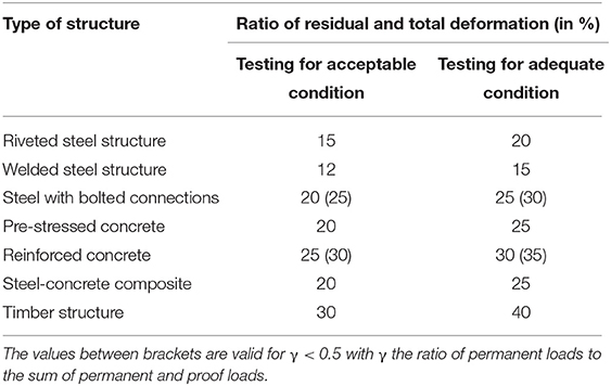
Table 4. Limitations to deviation between measured and calculated deformations (Hungarian Chamber of Engineers, 2013).
The limitations of the currently available stop criteria are as follows. The stop criteria from the German guideline are not applicable to structures with existing cracking, which is often the case for existing bridges. The stop criterion based on the steel strain requires removal of the concrete cover, and is thus not often used in practice. The Czech and Slovak codes provide acceptance criteria, which serve a different purpose than stop criteria, and can thus not be used for monitoring structural safety during a proof load test. The stop criteria from the Spanish guidelines are developed for diagnostic load tests for new bridges prior to opening. As such, they are not suitable for proof load testing of existing structures. Similar limitations are found in the other existing codes and guidelines mentioned before.
Proposed Stop Criteria for Flexure
Performance Requirements for Stop Criteria
The existing codes and guidelines contain stop criteria for flexure since flexure is a ductile failure mode. The first and foremost requirement for a stop criterion is that it should perform well: it should warn with sufficient anticipation for irreversible damage or failure. This requirement for a stop criterion is based on the basic definition of a stop criterion; if this requirement is not fulfilled, the stop criterion loses its meaning. At the same time, the stop criterion should not be so conservative that it causes a load test to be stopped prematurely. For this purpose, one should compare the stop criterion to the structural responses obtained with failure tests and with proof load tests. Comparing to failure tests gives insight in the margin of safety provided by the stop criterion. Comparing to proof load tests in which the bridge is instrumented extensively gives an idea about the performance of the stop criterion in terms of prematurely ending proof load tests. A third requirement for a good stop criterion is that theoretical principles should lie at its basis. The current codes and guidelines use arbitrary limits or limits related to the performance at the serviceability limit state. The latter element is suitable for acceptance criteria after a test to ensure the durability of the structure after the test, but do not give us insight in whether irreversible damage or failure is near or not. A final requirement for stop criteria for proof load testing of bridges is that the criterion should be based on a structural response that can be measured easily and with a robust measurement technique. The stop criterion should also be in line with the evolution toward non-contact measurements (Kohut et al., 2012).
The stop criteria developed in this paper are based on flexural theory. As such, they fulfill the third requirement for stop criteria. The proposed stop criteria use measurable quantities: strains, crack widths, and deflections; and as such fulfill the first requirement. With the information from available failure tests and proof load tests, we then check if the proposed stop criteria fulfill the first two requirements for stop criteria.
Theoretical Derivation
Limiting Strain in the Concrete
To find a limiting strain in the concrete, the stress in the tension steel is limited to 65% of the mean yield stress fym. This criterion avoids stresses in the steel to reach the yield stress with a considerable margin of safety, so that larger deformations in the structure are avoided. Based on the limiting stress in the tension steel, we can derive the stresses and strains in the cross-section. For a singly reinforced rectangular concrete beam, Figure 2 shows the section, strains, stresses, and resultant forces.
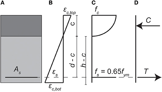
Figure 2. Singly reinforced rectangular concrete beam at moment of achieving stop criterion for concrete strain based on flexural theory: (A) cross-section of beam; (B) strains; (C) stresses; (D) resultant forces. Modified from (Lantsoght et al., 2018).
The strain at the bottom of the cross-section εc, bot corresponds to the stress state of 65% of the yield stress in the tension steel, assuming that the strains are linear over the height of the cross-section. For the case with tension on the bottom of the cross-section, the strain in the concrete εc, bot is related to the strain in the steel εs following equivalent triangles:
The geometry in Equation (10) considers the height h, the effective depth d, and the compression zone c. For the limit on the steel stress of 65% of the yield strength, Equation (10) can be rewritten as a function of the limiting steel stress, resulting in the maximum stress εc, bot, max:
with fym the mean yield stress of the steel, and Es the Young's modulus of the steel. To find the height of the compression zone, the stress-strain relation for concrete can be expressed with Thorenfeldt's parabola, see Figure 3. The expressions of the parabola are a function of the maximum strain in the concrete under compression εc, comp, which for the case in Figure 2 with tension on the bottom corresponds to εc, top. The following material parameters are required for defining the parabola:
To describe both pre- and post-peak behavior in the stress-strain relationship, the factor kth is introduced. The following expressions then describe the parabolic relation between stresses and strains in the concrete:
The factor βth converts the concrete stress from the maximum stress fc, th to the average stress βth × fc, th:
To fulfill horizontal equilibrium, the resultant under compression C and the resultant under tension T should be equal. The value of the height of the compression zone c should be calculated (analytically or iteratively) so that the equilibrium condition is fulfilled. The expressions for the force resultants are:
Once εc, bot, max is calculated for the value of the height of the compression zone c which corresponds to the limit of 65% of the yield stress in the steel, a stop criterion for the strains εstop can be defined based on this limiting strain and taking into account the strain εc0 caused by the permanent loads:
Since the tensile strain in the concrete is highly non-uniform, the proposed stop criterion refers to an averaged tensile strain over a length that includes at least one crack. The contribution of this crack is then smeared over this length. We recommend the use of a horizontally placed LVDT, measuring over 1 m length for the evaluation of this stop criterion.
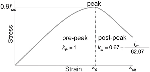
Figure 3. Stress-strain parabola of concrete, with fcm in MPa. Modified from (Lantsoght et al., 2018).
Limiting Crack Width
The limiting crack width wstop results from the theoretical model for crack width in reinforced concrete members subjected to bending of Frosch (1999). The advantage of the model by Frosch is that the resulting crack width is suitable for larger concrete covers, as present in real structures. The limiting stress in the reinforcement steel is again 0.65fym, as used for the stop criterion for the strains. According to Frosch, the maximum crack width wc in a reinforced concrete member subjected to bending is:
with fs the stress in the steel, Es the Young's modulus of the reinforcement steel, dc the concrete cover to the centroid of the tension steel, s the reinforcement spacing, and βfr the strain gradient term, given as:
The value of βfr can be approximated as:
with dc in mm To derive a suitable stop criterion, the effect of the permanent loads needs to be taken into account, and the limiting steel stress needs to be implemented in Equation (20). The resulting limiting crack width wstop is:
with the stress caused by the permanent loads fperm:
with c in Equations (24) and (21) the height of the compression zone that corresponds with 0.65fym as a stress in the reinforcement steel.
Proposal
Figure 4 gives an overview of the proposed stop criteria for flexure. Preliminary tests (Lantsoght et al., 2017i) showed that the behavior of beams previously cracked in bending is different from beams not cracked in bending, and therefore the proposal separates both cases. For the proposed stop criteria, the only difference between the case of a beam previously cracked in bending and a beam not previously cracked in bending lies in the limit to the residual crack width wres. Note that for a beam previously cracked in bending the crack width w, the maximum crack width wmax, and residual crack width wres can be the width of a newly developed crack or the increase in width of an existing crack.
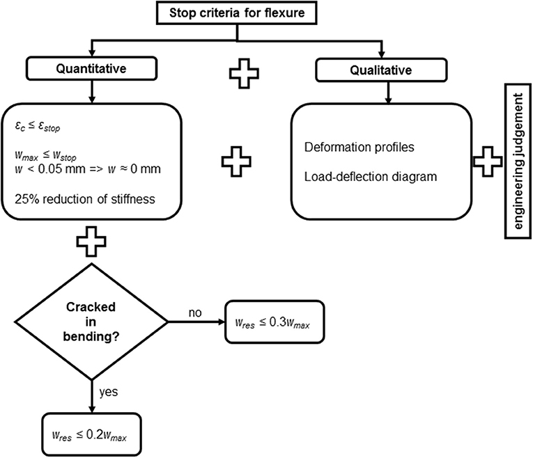
Figure 4. Currently proposed stop criteria for flexure.
Figure 4 gives the two theoretically derived stop criteria from Equation (19) for strain and Equation (23) for the maximum crack width. In addition to these stop criteria, Figure 4 proposes to neglect all cracks that are smaller than 0.05 mm. The limit for the residual crack width wres as a function of the maximum crack width wmax is taken from the German guideline, see Table 1. To limit non-linearity, we propose to limit the reduction of the stiffness determined in the load-deflection diagram to maximum 25%.
In addition to these quantitative stop criteria, Figure 4 contains qualitative stop criteria. The test engineer should follow the overall structural behavior during the load test based on the load-deflection diagram and deformation profiles. After the test, the behavior of the load-deflection diagram is evaluated with the reduction in stiffness. Examples of deformation profiles include lines of deflections in the longitudinal direction and transverse direction, resulting in plots that give insight in the overall structural behavior during the load test. Changes in these profiles indicate changes in the load distribution behavior. During the load test, the test engineer should interpret such changes.
Verification of Proposed Stop Criteria
Available Experiments
Laboratory Tests
Two series of experiments serve for the comparison between the proposed stop criteria and the results obtained in the laboratory. The beams in these experiments are subjected to a loading protocol that is similar to the cyclic loading protocol recommended for proof load testing. As such, these experiments are suitable for comparison to the stop criteria that are proposed for use in the field. Since these beams were tested to failure, the measured structural responses give an indication of the margin of safety to collapse when these are compared to the stop criteria.
The first series, the P series, consists of two beams with plain bars cast in the laboratory (Lantsoght et al., 2017h). Four experiments were carried out, two of which resulted in a flexural failure. The second series, the RSB series, consists of beams sawn from the slab of the Ruytenschildt Bridge (Lantsoght et al., 2016b). This series consisted of five tests on three beams. The four tests that resulted in a flexural failure are included in this study. Table 5 gives an overview of the properties of the tested beams and the maximum applied load Pmax. For the RSB beams, the given area of the cross-section Ac is the area of the cross-section of the beam sawn from the bridge. Since sawing does not lead to a rectangular cross-section, the value of Ac is the area of the actual section, not the product of the height and the average width b. All experiments summarized in Table 5 are three-point bending tests on beams with a span length lspan and a center-to-center shear span a.
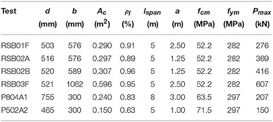
Table 5. Overview of properties of beams tested in the laboratory failing in flexure.
Field Tests
Two types of field tests are available: proof load tests and failure tests (collapse tests). The available results from proof load tests are part of the series of pilot proof load tests from the Netherlands (Lantsoght et al., 2017e). Four bridges and viaducts were proof loaded to evaluate the failure mode of flexure: the viaduct Vlijmen Oost (Fennis et al., 2014), the Halvemaans Bridge (Fennis and Hordijk, 2014), the viaduct Zijlweg (Lantsoght et al., 2017b), and the viaduct De Beek (Lantsoght et al., 2017c,f), see Table 6. Vlijmen Oost carries three lanes, De Beek originally carried two lanes but is restricted to one lane, and the Halvemaans Bridge and Zijlweg carry a single lane. Vlijmen Oost was tested with a loading truck (Steffens et al., 2001) whereas the other bridges were loaded with a system of a steel spreader beam, counterweights, and hydraulic jacks. The proof load tests on the Halvemaans Bridge and viaduct Zijlweg directly showed that these structures fulfill the code requirements. The proof load test on Vlijmen Oost required a combination with finite element models to assess the bridge, since the applied load was small as compared to the code-prescribed load for a viaduct with three lanes. On viaduct De Beek, the test was limited for safety reasons to the first span, which does not cross the highway. However, the second span is critical and thus other assessment methods are required to evaluate viaduct De Beek and to evaluate if the bridge can be opened again for two lanes of traffic.
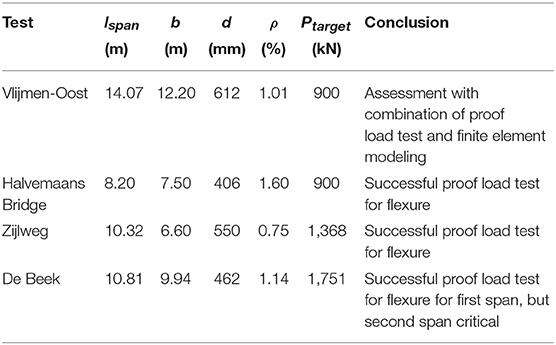
Table 6. Overview of properties of pilot proof load tests for flexure.
The sensors plan of these pilot tests was very extensive, so that the structural behavior could be followed in detail. The conclusion from the analysis of the behavior was that the proof load test did not result in irreversible damage to the structure. For the stop criterion to fulfill its aim, it should thus not be exceeded in these experiments when we reanalyze the measured structural responses. When the stop criterion performs adequately, future proof load tests can be done with less instrumentation (thus being more economic and taking less time). The sensor plan then only consists of the instrumentation required to evaluate the stop criteria.
Besides the pilot proof load tests, a failure test on slab bridge, the Ruytenschildt Bridge (Lantsoght et al., 2016a,b,c,d, 2017d), was carried out. The Ruytenschildt Bridge was a bridge with five spans of 9 m long and a width of 12 m. For testing and staged demolition, a saw cut was introduced, leaving a structure with a width of 7.365 m for testing. The bridge was tested in two spans at a shear-critical position. In the first span, the maximum applied load was 3,049 kN and the load was limited by the available counterweight. Failure did not occur, but flexural distress was observed. In the second span, the maximum applied load was 3,991 kN. The failure mode was a combination of settlement of the support and yielding of the reinforcement in the sagging moment region, resulting in large cracking. The deck did not collapse. Whereas these tests were intended to be shear tests, shear failure did not occur and we can use the results of these experiments to analyze the available margin of safety for the proposed stop criteria for bending.
Comparison Between Experiments and Stop Criteria
Comparison With Failure Tests
The tests in which failure was reached are used to evaluate the margin of safety provided by the proposed stop criteria for flexure. These tests are the laboratory tests and the failure tests on the Ruytenschildt Bridge. For the first span of the Ruytenschildt Bridge, the value of εc, bot, max = 1,061 με, which gives a stop criterion for the strain of εstop = 1,022 με. For the second span, εc, bot, max = 1,060 με so that εstop = 1,051 με. For the first span, the stop criterion for the crack width is calculated as wstop = 0.19 mm and for the second span the value is also wstop = 0.19 mm. Table 7 gives an overview for the loads at which each stop criterion is exceeded. The stop criteria for the case of a structure already cracked in bending are considered. In the first span, the stop criterion for the crack width is not exceeded, since the monitored crack was not activated during the test. This observation shows that punctual monitoring of crack widths during tests should be replaced with non-contact methods that can monitor all cracks in the region of interest. The stop criterion for the concrete strain is not exceeded in the first span, which can be explained by the fact that the experiment was not continued until failure was achieved but until the maximum available load was applied.
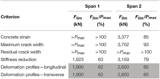
Table 7. Load Flim for which proposed stop criteria are exceeded and resulting margin of safety during failure tests on Ruytenschildt Bridge.
For both spans, the stop criterion that is exceeded first is the criterion related to the deformation profiles in longitudinal and transverse direction. This criterion is exceeded at 62% of the maximum applied load in span 1 and at 65% of the failure load in span 2, see Table 7. Note that the results for the evaluation of the load-displacement diagram are not included in Table 7, since this criterion is observed qualitatively in real-time during the test, and after the test it is converted in a quantitative measure of the reduction of the stiffness; both criteria serve the same purpose.
Table 8 gives an overview of the loads Flim for which the proposed stop criteria were exceeded, and the margin of safety Flim/Pmax for the governing stop criterion (or criteria). The stop criteria for a structure uncracked in bending are considered for the RSB beams and P804A1, since the RSB beams are taken out of their original structural system, whereas P804A1 is newly cast. Only P502A2 is considered previously cracked in bending, since it is a repeat test on the beam P502. For P502A2, no unloading branches were included in the loading protocol, so that the residual crack cannot be determined and the associated stop criterion cannot be evaluated. For the RSB experiments, the measurements of two lasers on each side of the beam give rather different results for the reduction in the stiffness. Therefore, the two values of these results are given in Table 8. However, the variability in the results stems from the fact that the beams are not straight since they were sawn from the bridge. Therefore, for this particular case, the stiffness reduction is not considered a reliable stop criterion, and the results are indicated in italic in Table 8. Table 8 also gives the calculated values for the maximum crack width and the maximum strain for direct comparison to the values recommended by the German guideline (Deutscher Ausschuss für Stahlbeton, 2000). The results show that the limiting strain from the proposed stop criteria is higher than the strain limit from the German guideline, whereas the limiting crack width is smaller than the limit from the German guideline.
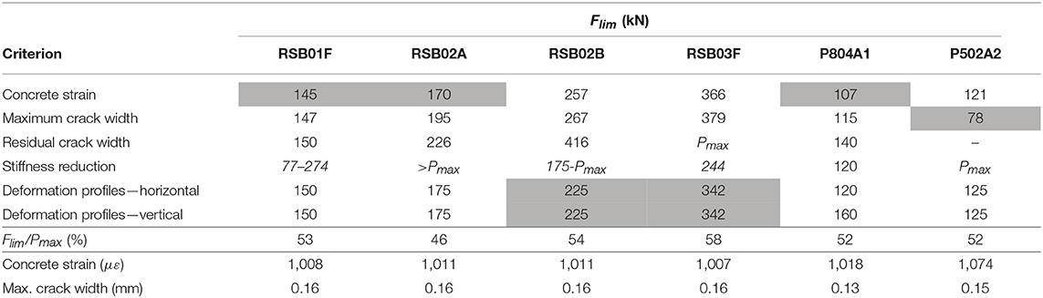
Table 8. Limits from proposed stop criteria, load Flim for which proposed stop criteria are exceeded and resulting margin of safety during laboratory tests on beams.
The results in Table 8 show that there is not a single stop criterion that is governing for each beam experiment, but that all stop criteria should be evaluated. The stop criteria are exceeded with a margin of safety between 42 and 61% and are thus conservative for use in practice. The results also show that the load for which the stop criterion for the limiting strain is exceeded is similar to the load for which the stop criterion for the limiting crack width is exceeded. This observation is expected, since both stop criteria are related to a maximum stress in the reinforcement steel of 65% of the yield stress.
Comparing the results from Table 8 to the results from Table 7 shows that a similar, yet slightly smaller margin of safety is found for the failure tests on an existing bridge. The margin of safety on the Ruytenschildt Bridge is slightly smaller, since in the first span, loading was not continued until collapse, whereas in the second span, perhaps more load could have been carried if the substructure would not have failed. The resulting margin of safety is sufficiently conservative to recommend these stop criteria for the application to proof load tests on reinforced concrete structures that are flexure-critical and are expected to fail in a ductile manner.
Comparison With Pilot Proof Load Tests
In this part, the available pilot proof load tests are analyzed to see if the proposed stop criteria are not overly conservative and would have resulted in a premature termination of these tests. Table 9 gives an overview of the proposed stop criteria for the pilot proof load test for bending. For the Halvemaans Bridge, the strain due to the permanent loads εc0 is estimated with a conservative hand calculation, whereas for Zijlweg and De Beek this value is taken from the finite element model used to prepare the test. For Vlijmen Oost, this value is derived from the bending moment caused by the permanent loads from the finite element model used to assess the viaduct. For all cases, crack widths smaller than 0.05 mm are taken as equal to 0 mm. Therefore, for all experiments, the maximum residual crack width is negligible. The results for wres, lim also show that for many cases the resulting limit is negligible. The reduction in stiffness for the Halvemaans Bridge is given as “+-0,” since the value of the stiffness slightly increased over the load cycles. The longitudinal deflection profiles “LD” and transverse deflection profiles “TD” are qualitatively studied. If there are no observations during the entire proof load test, the stop criterion is never exceeded and “>Ftarget” is added to Table 9. For Vlijmen Oost, no measurements for the deflection in the transverse direction are available, so that “NA” is shown in Table 9 for this stop criterion. For the Halvemaans Bridge, in the last load step the deflections increased larger than expected, so that the stop criterion for the longitudinal deflection profiles is reached in the last load step. For none of the pilot proof load tests, a stop criterion was exceeded during the test. This conclusion corresponds with the conclusions from each of the proof load tests, where an analysis of the structural responses measured with the extensive instrumentation plans showed that no irreversible damage occurred during the proof load tests.
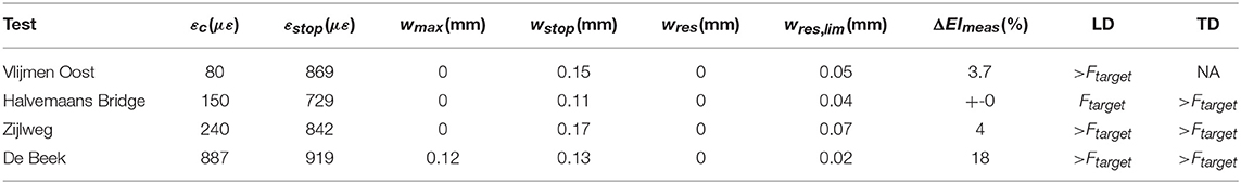
Table 9. Comparison between proposed stop criteria and measurements obtained from pilot proof load tests for flexure.
Discussion and Future Research
The proposed stop criteria for flexure are evaluated in two ways. First, we checked if the margin of safety on the proposed stop criteria is sufficient when compared to failure tests. Since the margin of safety ranges from 42 to 65%, the stop criteria provide sufficient conservatism. Secondly, we checked if the proposed stop criteria are not overly conservative. The requirement for this evaluation parameter is that in the heavily instrumented pilot proof load tests, the measured structure responses should never exceed the proposed stop criteria. Table 9 shows that the proposed stop criteria fulfill this requirement.
The proposed stop criteria for flexure are an improvement of the state of the art. The existing codes and guidelines contain stop criteria for flexure, but the limits on strains and crack widths that are provided are arbitrary or related to serviceability requirements. To function as a stop criterion, the limit should be linked to the onset of non-linear behavior and have a theoretical background. The proposed stop criteria fulfill this requirement, since they are related to reaching 65% of the yielding stress in the reinforcement steel. These stop criteria can be easily programmed in a spreadsheet, and the limiting values can be read off from this spreadsheet during the preparation stage of a proof load test. The limits related to serviceability requirements can be used for acceptance criteria, but do not serve the purpose of stop criteria.
The proposed stop criteria do not include limits to the largest deflection and residual deflection, as most existing codes and guidelines. The reason why deflection and residual deflection are not included is that beam experiments (Lantsoght et al., 2016d, 2017i) indicated that a stop criterion based on a maximum and residual deflection is not reliable. The German guidelines (Deutscher Ausschuss für Stahlbeton, 2000) contain a limiting strain in the steel reinforcement. A similar stop criterion is not included in the proposal, since measuring the steel strain requires the removal of the concrete cover. Most bridge owners are not keen on inflicting such damage to a bridge.
All pilot proof load tests had a flexure-critical section in the sagging moment region. This situation is common for reinforced concrete slab bridges. Typically, higher reinforcement ratios, and sometimes larger cross-sections are used in the hogging moment region. If, however, the engineer needs to assess a bridge where the flexure-critical section lies in the hogging moment region, the practical application of the proposed stop criteria may be more complicated. The presence of an asphalt layer may make instrumenting the tension side of the cross-section more complicated. For those cases, load application and instrumentation occur on the same side of the cross-section, which may complicate execution, wiring, and positioning details of the load and the sensors. Future work based on case studies of bridges that are flexure-critical in the hogging moment region should address these issues.
One limitation in terms of instrumentation in the pilot proof load tests is the use of contact sensors. To measure the crack widths, we selected one or more existing cracks to monitor during the test. The selected crack(s) may or may not have been the governing crack during the test. Similarly, we measured the strain at one position only. To avoid this limitation, non-contact measurements should be used and this instrumentation should monitor the entire region of interest. Possible options are the use of photogrammetry measurements to monitor the entire region of interest, or the use of fiber optics to check strains over a larger length or surface. To improve the current practice of proof load testing, the application of better measurement techniques should be studied together with the improved stop criteria.
Summary and Conclusions
In proof load tests, a load representative of the factored load combination is placed on a structure to show directly that this structure can carry the code-prescribed loads without problems. Since proof load testing involves large loads, it is necessary to evaluate if the test is safe in real-time. Stop criteria are limits to the structural responses that are evaluated in real-time during the test to evaluate the safety. A number of existing codes and guidelines for proof load testing contain stop criteria for flexure, including the German guideline for load testing, the Czech and Slovak codes, and the Spanish guidelines. In most cases, however, the available stop criteria are arbitrary limits, or related to serviceability requirements. Serviceability requirements should dictate acceptance criteria, not stop criteria, since they give no information about structural safety, but about future durability.
To develop stop criteria that give information about structural safety, the theory of flexure in reinforced concrete beams was used. This theoretical basis results in a stop criterion for the concrete strain. Using the theoretical work on the maximum crack width of reinforced concrete elements in bending resulted in a stop criterion for the crack width. The set of stop criteria is completed with the limit to the residual crack width from the German guideline, a limit to the stiffness reduction, and a qualitative evaluation of deflection or deformation profiles and the load-deflection profile.
The evaluation of the stop criteria uses two requirements. The first requirement is that the comparison to failure tests should show sufficient margin of safety. For this purpose, the proposed stop criteria are compared with the results of two series of beam experiments from the laboratory and the failure tests on the Ruytenschildt Bridge. The margin of safety lies between 42 and 65% for the proposed stop criteria and thus fulfills this requirement. The second requirement is that the stop criteria should not be overly conservative. We evaluated this requirement by comparing the proposed stop criteria to the measured structural responses from a series of pilot proof load tests. These bridges were heavily instrumented, and the conclusion from these proof load tests was that the test did not lead to irreversible damage. The analysis of the stop criteria, which use fewer sensors, leads to the same conclusion. The proposed stop criteria thus fulfill the two requirements and can be proposed for proof load tests on reinforced concrete structures that are flexure-critical.
Author Contributions
EL: theoretical work, experiments, and manuscript writing. YY: discussions of proposed stop criteria and experiments. CvdV: supervision of experiments and modifications to manuscript. DH: coordination of load testing research. AdB: practical perspective of proposal.
Funding
The experimental part of this research was funded by the Dutch Ministry of Infrastructure and the Environment (Rijkswaterstaat), the Province of Noord Brabant, the Province of Friesland, and the Province of Noord Holland. The desk research was funded by the program of Chancellor Grants 2016 from Universidad San Francisco de Quito. The APC is covered by the OA fund of Delft University of Technology.
Conflict of Interest Statement
AdB was employed by company De Boer Consultancy, however company De Boer Consultancy was not involved with this study in any capacity.
The remaining authors declare that the research was conducted in the absence of any commercial or financial relationships that could be construed as a potential conflict of interest.
Acknowledgments
The authors wish to express their gratitude to the Province of Friesland, the Province of Noord Holland, the Province of Noord Brabant and the Dutch Ministry of Infrastructure and the Environment (Rijkswaterstaat) for financing the pilot proof load tests. This research would not have been possible without the contributions and help of our colleagues from Delft University of Technology A. Bosman, S. Ensink, S. Fennis, P. van Hemert, R. Koekkoek, and W. Vos, of the contractor de Boer en de Groot, involved with the Ruytenschildt Bridge test, of F. Linthorst and D. den Boef of Witteveen+Bos, responsible for practical preparations and safety inspections on site at the viaducts Zijlweg and De Beek, and of O. Illing and the late C. Huissen from Mammoet, responsible for applying the load. The many discussions with S. Fennis, M. Naaktgeboren, and H. van der Ham of the Dutch Ministry of Infrastructure and the Environment have been crucial in the development of this research, and are gratefully acknowledged. For the desk research on the theoretical derivations of the stop criteria, funding was obtained through the program of Chancellor Grants from Universidad San Francisco de Quito. This funding is gratefully acknowledged.
References
AASHTO (2016). The Manual for Bridge Evaluation With 2016 Interim Revisions. Washington, DC: American Association of State Highway and Transportation Officials.
ACI Committee 437 (2013). Code Requirements for Load Testing of Existing Concrete Structures (ACI 437.2M-13) and Commentary. Farmington Hills, MI: ACI Committee 437.
Aguilar, C. V., Jáuregui, D. V., Newtson, C. M., Weldon, B. D., and Cortez, T. M. (2015). “Load rating a prestressed concrete double-tee beam bridge without plans by proof testing,” in Transportation Research Board Annual Compendium of Papers (Washington, DC).
Bonifaz, J., Zaruma, S., Robalino, A., and Sanchez, T. A. (2018). “Bridge diagnostic load testing in ecuador – case studies,” in: IALCCE 2018 (Ghent).
Ceský normalizační institut (1996). CSN 73 6209 (736209) Loading Tests of Bridges (ZatěŽovací zkoušky mostu) (Prague).
Chen, X., Yang, Y., Evangeliou, P., and van der Ham, H. (2018). “Critical proof load for proof load testing of concrete bridges based on scripted fem analysis,” in IALCCE 2018 (Ghent).
Deutscher Ausschuss für Stahlbeton (2000). DAfStb-Guideline: Load Tests on Concrete Structures (in German) (DAfStb-Richtlinie: Belastungsversuche an Betonbauwerken). Berlin: Deutscher Ausschuss fur Stahlbeton.
Faber, M. H., Val, D. V., and Stewart, M. G. (2000). Proof load testing for bridge assessment and upgrading. Eng. Struct. 22, 1677–1689. doi: 10.1016/S0141-0296(99)00111-X
Fennis, S. A. A. M., and Hordijk, D. A. (2014). Proof Loading Halvemaans Bridge Alkmaar (in Dutch). Delft: Delft University of Technology.
Fennis, S. A. A. M., van Hemert, P., Hordijk, D., and de Boer, A. (2014). Proof loading Vlijmen-Oost; research on assessment method for existing structures (in Dutch). Cement 5, 40–45. Available online at: https://www.cementonline.nl/artikel/proefbelasting-viaduct-vlijmen-oost
Filar, Ł., Kałuza, J., and Wazowski, M. (2017). Bridge load tests in Poland today and tomorrow – the standard and the new ways in measuring and research to ensure transport safety. Proc. Eng. 192, 183–188. doi: 10.1016/j.proeng.2017.06.032
Frosch, R. J. (1999). Another look at cracking and crack control in reinforced concrete. ACI Struct. J. 96, 437–442.
Frýba, L., and Pirner, M. (2001). Load tests and modal analysis of bridges. Eng. Struct. 23, 102–109. doi: 10.1016/S0141-0296(00)00026-2
Halicka, A., Hordijk, D. A., and Lantsoght, E. O. L. (2018). “Rating of concrete road bridges with proof loads,” in ACI SP 323 Evaluation of Concrete Bridge Behavior Through Load Testing - International Perspectives, (Farmington Hills, MA), 16.
Hungarian Chamber of Engineers (2013). Guidelines for Interventions in Hungary (in Hungarian). Budapes: Hungarian Chamber of Engineers.
Kohut, P., Holak, K., Uhl, T., Krupinski, K., Owerko, T., and Kura,ś, P. (2012). Structure's condition monitoring based on optical measurements. Key Eng. Mater. 518, 338–349. doi: 10.4028/www.scientific.net/KEM.518.338
Kopácik, A. (2003). “Loading tests of highway bridges in Slovakia,” in 11th FIG Symposium on Deformation Measurements (Santorini).
Lantsoght, E.O. L., van der Veen, C., and de Boer, A. (2016a). “Shear and moment capacity of the Ruytenschildt bridge,” in IABMAS 2016 (Foz de Iguacu).
Lantsoght, E.O. L., Van der Veen, C., and Hordijk, D. A. (2018). “Monitoring crack width and strain during proof load testing,” in IABMAS 2018 (Melbourne, VIC).
Lantsoght, E. O. L., De Boer, A., and Van der Veen, C. (2017a). Levels of approximation for the shear assessment of reinforced concrete slab bridges. Struct. Concrete 18, 143–152. doi: 10.1002/suco.201600012
Lantsoght, E. O. L., Koekkoek, R. T., Hordijk, D. A., and De Boer, A. (2017b). Towards standardization of proof load testing: pilot test on viaduct Zijlweg. Struct. Infrastruct. Eng. 16, 365–380. doi: 10.1080/15732479.2017.1354032
Lantsoght, E. O. L., Koekkoek, R. T., van der Veen, C., Hordijk, D. A., and Boer, A. (2017c). Pilot proof-load test on Viaduct De Beek: case study. J. Bridge Eng. 22:05017014. doi: 10.1061/(ASCE)BE.1943-5592.0001131
Lantsoght, E. O. L., van der Veen, C., de Boer, A., and Hordijk, D. A. (2016c). Probabilistic prediction of the failure mode of the Ruytenschildt Bridge. Eng. Struct. 127, 549–558. doi: 10.1016/j.engstruct.2016.08.054
Lantsoght, E. O. L., Van der Veen, C., De Boer, A., and Hordijk, D. A. (2017d). Collapse test and moment capacity of the ruytenschildt reinforced concrete slab bridge. Struct. Infrastruct. Eng. 13, 1130–1145. doi: 10.1080/15732479.2016.1244212
Lantsoght, E. O. L., Van der Veen, C., De Boer, A., and Hordijk, D. A. (2017e). Proof load testing of reinforced concrete slab bridges in the Netherlands. Struct. Concrete 18, 597–606. doi: 10.1002/suco.201600171
Lantsoght, E. O. L., van der Veen, C., de Boer, A., and Hordijk, D. A. (2017f). Required proof load magnitude for probabilistic field assessment of viaduct De Beek Eng. Struct. 148, 767–779. doi: 10.1016/j.engstruct.2017.07.010
Lantsoght, E. O. L., van der Veen, C., Hordijk, D. A., and de Boer, A. (2017g). State-of-the-art on load testing of concrete bridges. Eng. Struct. 150, 231–241. doi: 10.1016/j.engstruct.2017.07.050
Lantsoght, E. O. L., Yang, Y., Tersteeg, R. H. D., van der Veen, C., and de Boer, A. (2016d). “Development of Stop Criteria for Proof Loading,” in IALCCE 2016 (Delft).
Lantsoght, E. O. L., Yang, Y., van der Veen, C., de Boer, A., and Hordijk, D. (2016b). Ruytenschildt bridge: field and laboratory testing. Eng. Struct. 128, 111–123. doi: 10.1016/j.engstruct.2016.09.029
Lantsoght, E. O. L., Yang, Y., van der Veen, C., de Boer, A., and Hordijk, D. A. (2017i). Beam experiments on acceptance criteria for bridge load tests. ACI Struct. J. 114, 1031–1041. doi: 10.14359/51689786
Lantsoght, E. O. L., Yang, Y., Van der Veen, C., De Boer, A., and Hordijk, D. A. (2017h). “Determination of loading protocol and stop criteria for proof loading with beam tests,” in fib Symposium 2017. (Maastricht).
Ministerio de Fomento - Direccion General de Carreteras (1999). Recomendaciones Para la Realizacion de Pruebas de Carga de Recepcion en Puentes de Carretera. Madrid: Ministerio de Fomento - Direccion General de Carreteras.
Ministerio de Fomento (2009). Instrucciones Para la Puesta en Carga de Estructuras (Pruebas de Carga Provisionales). Ministerio de Fomento.
Ministerio de Fomento (2010). Instrucción de Acciones a Considerar en Puentes de Ferrocarril (IAPF). Ministerio de Fomento.
Research Institute of Roads and Bridges (2008). The Rules for Road Bridges Proof Loadings (in Polish) (Zalecenia Dotyczace Wykonywania Badan pod Próbnym Obciazeniem Drogowych Obiektów Mostowych). Warsaw: Research Institute of Roads and Bridges.
Schmidt, J. W., Halding, P. S., Jensen, T. W., and Engelund, S. (2018). “High magnitude loading of concrete bridges,” in ACI SP 323 Evaluation of Concrete Bridge Behavior Through Load Testing - International Perspectives, (Farmington Hills, MA).
Slovak Standardization Institute (1979). STN 73 6209 (736209) Loading Tests of Bridges (ZataŽovacie Skúšky Mostov). Bratislava: Slovak Standardization Institute.
Steffens, K., Opitz, H., Quade, J., and Schwesinger, P. (2001). The loading truck BELFA for loading tests on concrete bridges and sewers (in German). Bautechnik 78, 391–397. doi: 10.1002/bate.200102600
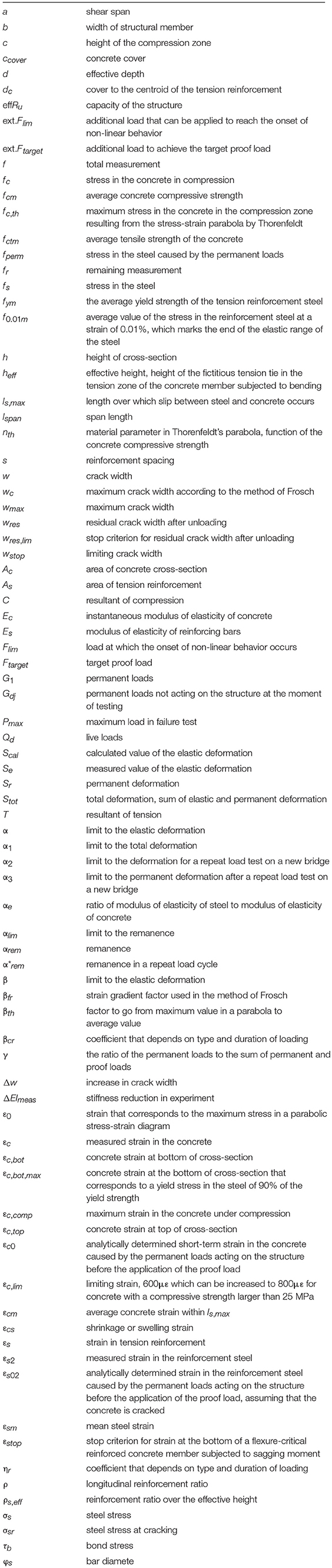
Notation List
Keywords: assessment, bending moment capacity, crack width, field test, proof load test, reinforced concrete, reinforced concrete bridge, strain
Citation:Lantsoght EOL, Yang Y, van der Veen C, Hordijk DA and de Boer A (2019) Stop Criteria for Flexure for Proof Load Testing of Reinforced Concrete Structures. Front. Built Environ. 5:47. doi: 10.3389/fbuil.2019.00047
Received: 05 February 2019; Accepted: 19 March 2019;
Published: 05 April 2019.
Edited by:
Emilio Bastidas-Arteaga, University of Nantes, FranceReviewed by:
Alfredo Camara, City University of London, United KingdomPiotr Olaszek, Road and Bridge Research Institute, Poland
Copyright © 2019 Lantsoght, Yang, van der Veen, Hordijk and de Boer. This is an open-access article distributed under the terms of the Creative Commons Attribution License (CC BY). The use, distribution or reproduction in other forums is permitted, provided the original author(s) and the copyright owner(s) are credited and that the original publication in this journal is cited, in accordance with accepted academic practice. No use, distribution or reproduction is permitted which does not comply with these terms.
*Correspondence: Eva O. L. Lantsoght, ZWxhbnRzb2dodEB1c2ZxLmVkdS5lYw==