 Tao Wang
 Qingxue Shang
 Xi Chen2
 Jichao Li
- 1Key Laboratory of Earthquake Engineering and Engineering Vibration, Institute of Engineering Mechanics, CEA, Harbin, China
- 2Beijing Institute of Architectural Design, Beijing, China
Pipes with a diameter of 150 mm, also called DN150, are often connected by grooved fit joints and employed as stem pipelines, which are used to transport water vertically to different building stories and distribute it horizontally to different rooms. A large deformability is often required for the grooved fit joints to accommodate the deformation concentrated between adjacent stories during an earthquake. To this end, the grooved fit joint is often improved with a wider groove to achieve such a large deformability. However, its seismic performance has not been thoroughly studied yet. This study conducted quasi-static tests on twelve DN150 grooved fit joints, including four elbow joints and eight DN150-DN80 Tee joints. The mechanical behavior, rotational capacity and failure mode were examined and discussed. The test results indicate that the fracture of the grooved fitting and the pull-out of pipes from the grooved fitting are the major damage patterns at deformations larger than 0.1 rad. At small deformations of <0.06 rad, although slight abrasions and wear were observed on the contact surface between the galvanized steel pipe and the grooved fitting, they would not result in significant leakage. Three damage states are defined accordingly, and the fragility models are developed for different grooved fit joints based on test results. Finally, seismic fragility analysis of DN150 stem pipeline system in a 10-story building was conducted. It is demonstrated that the improved joints survive under the maximum credible earthquake and the leakage is highly unlikely to occur.
Highlights
- Cyclic tests on grooved fit piping joints with large deformability.
- Experimental fragility models of grooved fit piping joints.
- Seismic fragility analysis of piping system based on probabilistic seismic demand analysis.
Introduction
Recent earthquakes have demonstrated that the non-structural components of critical facilities such as power plants, hospitals, and industrial units suffered much more damage in comparison with structural components, which mitigated the functionality of these critical facilities (Filiatrault and Sullivan, 2014; Dhakal et al., 2016). The pressurized fire sprinkler piping system is one of the most critical non-structural systems in a building. Its operational function is expected to be maintained after a destructive earthquake to prevent a subsequent fire disaster. However, the piping system was reported to be one of the most vulnerable non-structural systems in past earthquake disasters.
During the 1994 Northridge earthquake, pipelines with a diameter of <25 mm in different piping systems such as HVAC systems, sprinkler piping systems, and water piping systems experienced widespread failures (Fleming, 1998). Leakage of fire sprinkler piping systems forced the temporary evacuation of several hospital buildings after the earthquake (OSHPD, 1995; Ayres and Ezer, 1996). After the 2010 Chile Earthquake, four hospitals in the central south region of the country were inoperable, and 12 hospitals lost almost 75% of their functionalities. Most losses were caused by damages to non-structural components such as suspended ceilings, light fixtures, and fire sprinkler piping systems. The two largest airports in Chile were closed as well because of non-structural damages and flooding from failed sprinkler piping systems (Ju, 2011; Miranda et al., 2012; Tian et al., 2014). One typical fracture failure of the piping tee joints at the Santiago Airport is shown in Figure 1, which resulted in significant water leakage and further mitigated the functionality of the airport. Figure 2 shows the percentages of damaged piping systems over all investigated piping systems in previous earthquakes (Steinbrugge, 1982; McKevitt et al., 1995; Fleming, 1998; Global, 2001; Dillingham and Goel, 2002; LeGrone, 2004; Chock, 2006; Miranda et al., 2012). In the 2011 Tohoku Earthquake, about 8% of the investigated piping systems suffered damages, among which pipelines dominated with 49% of economic loss of the entire fire sprinkler system, as shown in Figure 3. It was also reported that 42% of the piping systems with damaged components exhibited water leakage during this earthquake which caused great inconvenience to earthquake rescue efforts (Mizutani et al., 2012; Soroushian et al., 2015a).
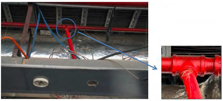
Figure 1. Fractured piping tee joint at the Santiago Airport after the 2010 Chile earthquake.
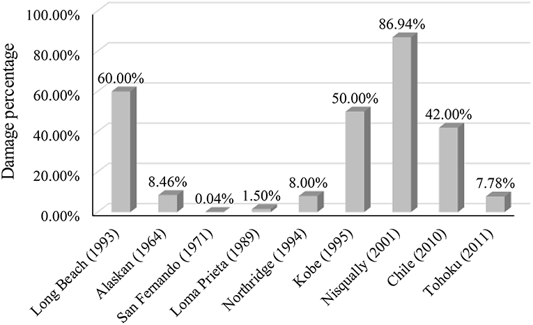
Figure 2. Statistics of the damaged piping systems over all investigated piping systems.
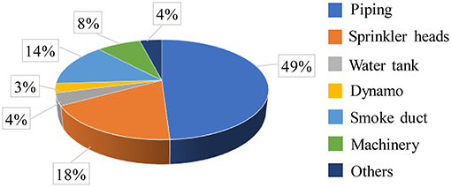
Figure 3. Component loss of fire sprinkler system in the Tohoku earthquake.
Several studies have investigated the seismic performance of piping systems. Antaki and Guzy (1998) conducted four-point bending tests on 16 pressurized pipe specimens with different types of joints. He et al. (2018) conducted a total of 72 cyclic tests on common water supply pipes to study the failure modes and seismic fragilities of Tee joints. Similar tests were performed by Blasi et al. (2018) to examine the hysteretic response of cast-iron and copper tee joints. Tian et al. (2014) and Soroushian et al. (2015b) tested 48 Tee joints including grooved fit joints under reversal cyclic loading to determine their rotational capacities. The damage states such as water leakage and fracture were identified. The grooved fit joints featured had a diameter no larger than 100 mm. Although the mechanical performance was stable, the leakage deformation was about 0.02 rad, implying high possibility of leakage during a rarely occurred earthquake. The seismic performance of piping system is also often examined by shaking table tests apart from quasi-static tests. Zaghi et al. (2012) investigated the seismic characteristics of welded and threaded tee joints of hospital piping systems under various intensities of seismic loading using a biaxial shake table. Tian et al. (2015) tested three full-scale pressurized sprinkler piping specimens with different materials, joint arrangements, and types of seismic bracings under dynamic loading. Jochen et al. (2018) studied the swing of CPVC sprinkler branch lines with tee joints under strong earthquake motions. Soroushian et al. (2014b) used the results of two shaking table experiments and numerical simulation of a hospital piping system to evaluate the probability of seismic damage to the piping system. The damage to the piping system itself and the pounding effects with adjacent objects such as walls, floors, and suspended ceilings are involved in the analysis. Three-dimensional dynamic response analyses on a suspended thin-wall water piping system under seismic floor motions were conducted by Tatarsky and Filiatrault (2019) to evaluate the fragility of thin-wall piping system.
Recently most public buildings in China have started to adopt pipes with large diameters, such as 150 mm (DN150), as the stem pipelines for fire sprinkler systems. The pipes are connected through grooved fit joints which are improved to accommodate larger rotations to avoid leakage at large deformations. Chinese style joints are quite different from American style ones and the seismic performance needs further study.
In this study, the configuration of the improved grooved fit joint is first introduced. Then, a series of quasi-static tests are conducted. The mechanical behavior, the rotational capacity and the failure mode are investigated, and fragility models are developed considering various damage states. Finally, a three-dimensional finite element model is constructed for a 10-story RC building where the DN150 pipeline system is installed to transfer water vertically along the height. Based on the probabilistic seismic demand model and fragility model obtained by experiments, probabilistic seismic fragility analysis is conducted for piping systems.
Quasi-static Test of Grooved Fit Piping Joints
Grooved Fit Joints With Large Deformation Capacity
Grooved fit joints, as shown in Figure 4, are a relatively new piping construction product that has gained popularity in earthquake prone areas because of the improved flexibility they provide to fire sprinkler piping systems. The grooved fit joint is composed of pipes with grooves, lathedog-plumbings, rubber gasket and bolts. Dimensions of 90° Elbow joint and Tee joint are presented in Figures 4B,C. Nominal size of 90° Elbow joint is 150 mm while the actual size is 165 mm. Nominal size of Tee joint is 150 × 80 mm while the actual size is 160 × 90 mm. Figures 4D,E present the deformation mechanism of the grooved fit joint. The gaps in the grooves and between the pipes make it possible to accommodate earthquake induced rotations. The lathedog-plumbings and pipe joints are made of cast iron and the water pipes are galvanized steel pipes. Detailed information of the materials and components can be found in Meide (2016).
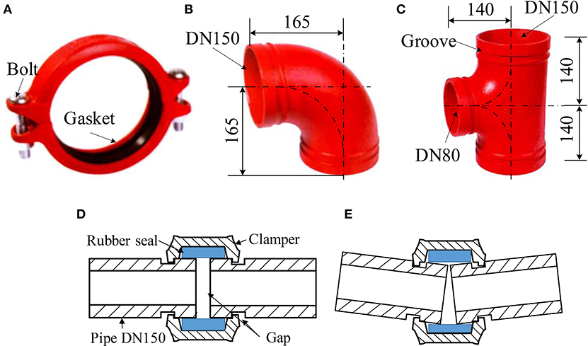
Figure 4. Sketches of grooved fit joints (A) Lathedog-plumbings (B) 90° Elbow joint (C) Tee joint (D) Before deformation (E) During deformation (Unit: mm).
Although this type of joint is massively used in piping construction in China, there's no sufficient investigation on its mechanical behavior, deformation capability, and failure mode. This study conducted three sets of quasi-static tests to examine the seismic performance of two types of grooved fit joints. The elbow joint employs a 90° elbow joint connected with two DN150 pipes, as shown in Figure 5A. The length of each pipe is 840 mm. The Tee joint uses a triplet connecting to two DN150 pipes and one DN80 pipe. The length of DN150 pipes is 840 mm, while the DN80 is 350 mm. Eight Tee joints are divided into two groups. One tests the rotation of DN150 pipes and the other tests the behavior of DN80, as shown in Figures 5B,C, respectively. In each group, there are one monotonic loading test and three cyclic loading tests.
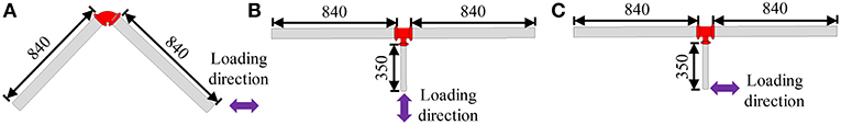
Figure 5. Dimensions of specimens (A) Elbow joint (B) Tee joint (DN150) (C) Tee joint (DN80) (Unit: mm).
Installation procedure of grooved fit joints is presented in Figure 6. Before the installation, lubricants are applied to the surface of rubber gasket. It is necessary to ensure that there is no gap between pipe end and joint. When tightening the bolts, take turns on both sides until the torque meets the installation requirements (60 Nm) and then the installation is completed.
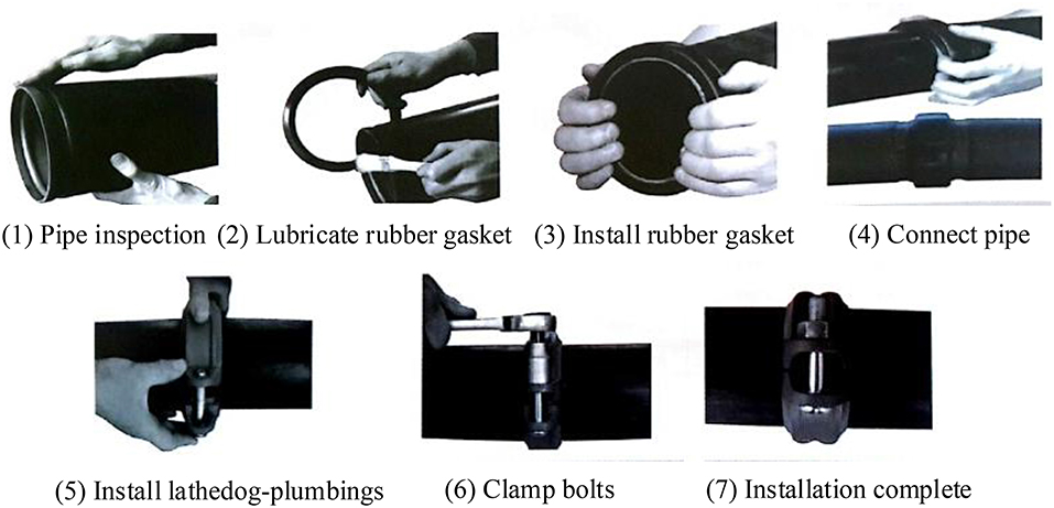
Figure 6. Installation procedure of grooved fit joints.
Experimental Setup and Loading Protocol
The functionality examination is one of the objectives of the experiment. The joints shall be tested with the internal water pressure. The maximum working pressure of water pipeline is 1.2 MPa. According to requirements of GB 50084-2001 (2001) and GB 50261-2005 (2005), the test pressure shall be increased by 0.4 MPa when the designed working pressure is >1.0 MPa. Therefore, all specimens will be filled with water and pressurized to 1.6 MPa to capture the leakage during the test and simulate the working condition of pipes. To achieve a precise water pressure, each DN150 pipe is perforated and welded with a DN32 pipe. One DN32 pipe is used as the water injection orifice to the water pump, while the other for the air escape and equipped with a ball valve to shut off the orifice once all the air has escaped. Then the water pressure will increase. Once the target pressure, 1.6 MPa in this study, is reached, the valve close to the pump will be shut off to maintain the water pressure. The pipes full of pressurized water will be kept for 24 h before tests to examine the sealing performance.
The Tee joints are to be tested in two patterns, one examining the rotation capacity of the triplet connected to DN150 pipes, the other testing the capacity of the triplet to the DN80 pipe, as shown in Figures 8B,C, respectively. The test setup for Tee joints (DN150) is shown in Figure 7. One hydraulic-servo actuator is employed to realize the quasi-static tests at a low loading speed of 0.5 mm/s. One end of the actuator is fixed on the reaction beam which is securely fixed on the strong floor. The other end is attached to a load jig which is bolted on two linear bearing sliders. The sliders restrain the movement of the load jig in the axial direction only. The end of each DN150 pipe is pinned to one reaction pier fixed on the strong floor, while the end of DN80 is connected to the load jig along the loading direction (see Figures 7, 8B). Similar set-ups are used to test the Tee joints (DN80) and the elbow joints. When testing the DN80 connection of the Tee joints, the DN80 pipe is pinned to the load jig perpendicular to the loading direction (see Figure 8C). It is worth noting that the load jig is lengthened using a steel component as shown in Figure 8C. The elbow joints are pinned to the load jig at one end and to the reaction beam at the other, as shown in Figure 8A. The axes of the initial positions of the two DN150 pipes of the specimen are 45 degrees from the horizontal line. More details of the test setup are presented in Shang et al. (2018).
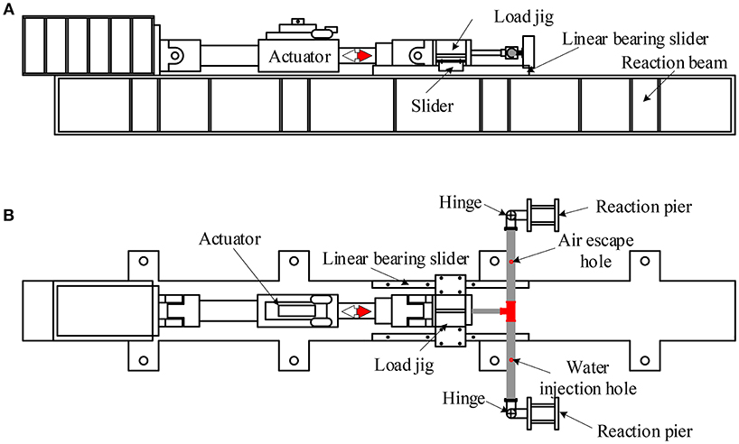
Figure 7. Experimental set-up for Tee joints (DN150) (A) Front view (B) Top view.
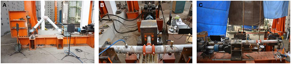
Figure 8. Specimens after installation (A) Elbow joint (B) Tee joint (DN150) (C) Tee joint (DN80).
The specimens were subjected to a cyclic loading following loading protocol suggested by FEMA 461 (2007), as shown in Figure 9. This protocol is commonly used for the seismic performance assessment of non-structural components and equipment, as it allows all damage states to be quantified to develop the corresponding fragility models. The loading protocol consists of repeated cycles with an amplitude that steadily increases by 1.4 times at each step. Two cycles of loading are conducted at each amplitude level. At least six cycles must be performed before any damage can be observed.
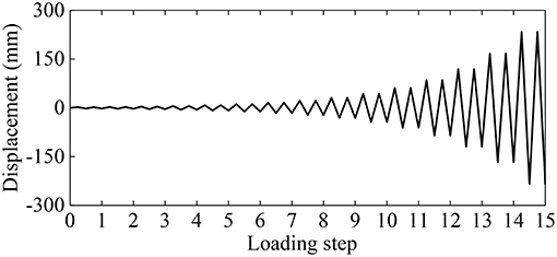
Figure 9. Loading protocol for cyclic tests suggested by FEMA 461 (2007).
Measurement Scheme
The bending moment of the Tee joints (DN150), M, was calculated using Equation (1), where F is the load applied by the actuator, and Di is the distance from the pin end of the pipe to the center of the triplet. The bending moment of the Tee joints (DN80) and the Elbow joints can be calculated in a similar way:
Full field displacement and strain measurement with high speed 3D digital image correlation (DIC) system is used for the measurement of strain and rotation in this study. DIC method is a powerful digital image correlation technique that gives the full-field strain distribution across a specimen (Reedlunn et al., 2011). The pipe surface is sprayed with black and white speckle. The measurement system tracks the speckle changes and uses the optimized 3D DIC algorithm to calculate the displacement and strain. The measured strain using DIC method can cover the range from 0.005 (50 micro-strains) to 2,000%. During the loading process, water leakage will first happen at one end of the joints. Therefore, the rotations of all pipes connected to the joints are measured and the one with the first damage will be adopted to quantify the damage states. The rotation is defined as the relative rotation angle between the joint and the pipeline and can be obtained in the post-processing software of the high speed 3D digital image correlation (DIC) system.
Meanwhile, four strain gauges are pasted on each pipe of the specimen, as shown in Figure 10. The curvature of each section is measured by two strain gauges respectively attached to the top and bottom of the pipes, as formulated in Equation (2), where, κ represents the curvature of the measured section, ε1 and ε2 are the strains measured from the strain gauges, and s is the interval between two strain gauges (pipe diameter in this study). The moment M of the section is then calculated with Equation (3), where E is the young's modulus, and I is the moment of inertia of the concerned section. The distribution of bending moment along the pipe is assumed to be linear. The calculated bending moments of the two measuring points on the failure side are used to obtain that at the pipe joint section by linear assumption. The data measured from strain gauges will be used to calibrate the optical measurement and compared with the bending moment calculated using the method of Equation (1).
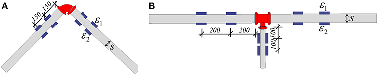
Figure 10. Measurement scheme of strain gauges (A) Elbow joint (B) Tee joint (Unit: mm).
Experimental Results of Grooved Fit Piping Joints
Physical Damages of Grooved Fit Piping Joints
The observed damage at first leakage was consistent for all specimens tested. Table 1 lists and shows photographs of the observed damages. The main failure modes were the fracture of coupling flanges and the pulling-out of pipes. Slight wear at interface between pipes and joint can be observed at DN150 pipes and heavy wear can be observed at DN80 pipes but the wear didn't cause any leakage and did no harm to the functionality of the pipes, which implies a good sealing performance of the improved joint.
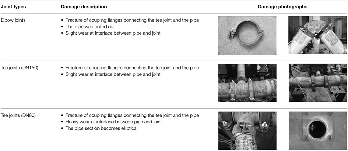
Table 1. Observed physical damages of grooved fit joint specimens.
Rotation Capacities of Grooved Fit Joints
Three damage states (DS) of grooved fit joints are defined based on the test results. DS1 represents the case in which pressure in the pipe drops to 85%, DS2 represents massive leakage when the water pressure drops to 0 MPa, and DS3 represents complete damage of the joints, including the resistance force dropping to 85% of the peak force, visible cracks, and the pipe pull-out. The rotations corresponding to different damage states for each specimen are compared in Figure 11, both monotonic and cyclic test results are given. All types of joints exhibit large rotational capacities ranging from 0.054 to 0.274 rad before massive leakage. Rotational capacity of the DN80 Tee joint is much larger than that of the DN150 Tee joint and the Elbow joint. The monotonic rotational capacities of massive leakage (DS2) are larger than their corresponding cyclic rotational capacities. This result is consistent with the results of Tian et al. (2014).
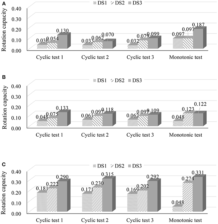
Figure 11. Measured rotations for all specimens (A) Elbow joint (B) Tee joint (DN150) (C) Tee joint (DN80) (Unit: rad).
Moment-Rotation Cyclic Response of Grooved Fit Joints
The measurement scheme provides two methods to obtain the bending moment of the concerned sections. Figure 12 shows the measured hysteretic curves from DIC and strain gauges, respectively. The moment of DIC curve is calculated using the method of Equation (1), while that of strain gauge is calculated using the method of Equations (2, 3). They measured generally well. And in the following discussion, the data measured from DIC will be used. Typical moment vs. rotation hysteretic curve of each type of grooved fit joint is shown Figure 13. The occurrence of massive leakage (DS2) is indicated by a solid red dot on each plot. After massive leakage, the tests were continued up to complete damage (DS3) of the test specimens. It can be observed from the hysteretic loops that the moment values would keep increasing even at a large rotation around 0.1 rad. And a pinching effect was introduced by the gaps in the improved configuration. As soon as the load intensity was increased, during the load-inversion phase, the gap generated caused relative rotations with near-zero force variation. Furthermore, reduction of the reloading stiffness can be observed after each loading step because the response could be highly influenced by the cumulative damage.
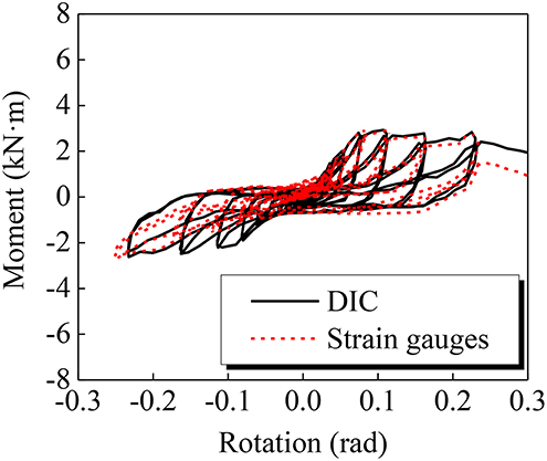
Figure 12. Comparison of results measured from DIC and strain gauges.
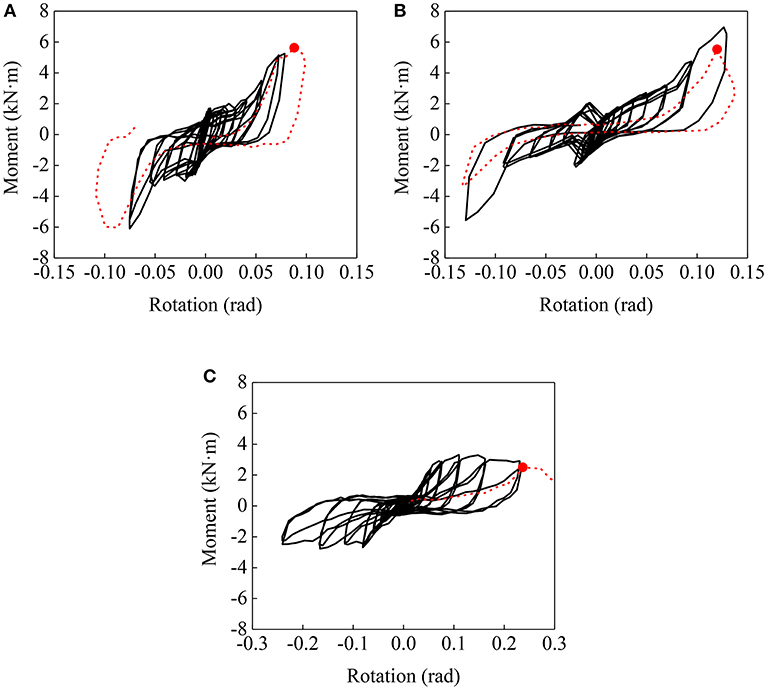
Figure 13. Moment-rotation behavior (A) Elbow joint (B) Tee joint (DN150) (C) Tee joint (DN80).
Experimental Fragility Analysis of Grooved Fit Joints
The experimental results of the cyclic tests were processed to develop the seismic fragility models for grooved fit joints. The cyclic behavior of the piping joints was governed primarily by joint rotation, and this is the only engineering demand parameter (EDP) considered. The three damage states were considered in the seismic fragility analysis, i.e., pressure dropping, massive leakage, and complete mechanical failure, corresponding to DS1, DS2, and DS3, respectively. Based on the method proposed by Porter et al. (2007), experimental fragility curves were defined for the three joint types based on the measured rotational capacities given in Figure 11. The median rotational capacity, θm, and associated logarithmic standard deviation, βt, were computed by Equations (4, 5).
where θi denotes the i-th measured rotational capacity and M is the number of cyclic tests conducted for this type of joints (M = 3 in this study). Considering the fact that the specimen number is <5 and all specimens experienced the same loading history, a correction factor βu = 0.25 is introduced in the calculation of logarithmic standard deviation and the modified logarithmic standard deviation β is calculated by Equation (6). Table 2 summarizes the median rotational capacity and logarithmic standard deviation obtained for each type of joint. Figure 14 compares all the fragility curves derived from the experimental data. The fragility curves of water leakage damage state (DS2) are further compared with the results of Tian et al. (2014) in Figure 15, where GFC50.8 (3.8) represents the pipes with diameter of 50.8 mm and the pipe wall thickness is 3.8 mm. It can be found that the rotation capacities of Chinese style joints are quite larger than those of American style joints. It is worth noting that more tests are needed for detail comparison to consider the influence of pipe diameter and pipe wall thickness.
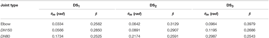
Table 2. Summary of fragility parameters.
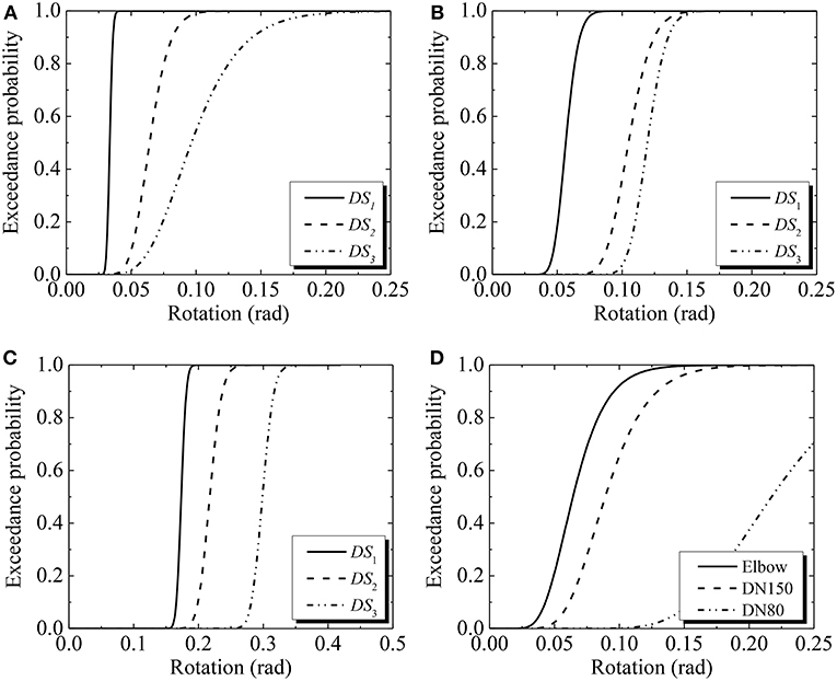
Figure 14. Fragility curves for different grooved fit piping joints (A) Elbow joint (B) Tee joint (DN150) (C) Tee joint (DN80) (D) Fragility curves of massive leakage (DS2).
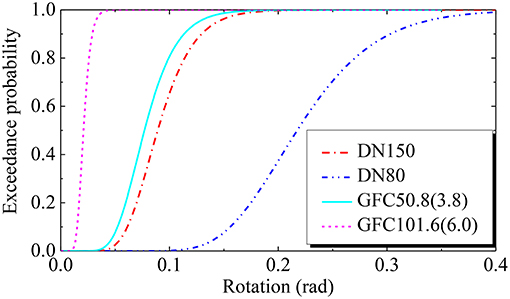
Figure 15. Comparison of fragility curves of water leakage damage state for grooved fit joints.
Building Specifications for the Case Study
A 10-story reinforced concrete (RC) frame was used for the case study of grooved fit piping joints. The story heights for the first two stories are 3.8 and 3.95 m, respectively, while the height of the penthouse is 3.9 m. The height of the remaining stories is 3.45 m. Uniformly distributed dead and live loads on each floor were 3.0 and 2.0 kN/m2, respectively and those for the roof were 4.0 and 0.5 kN/m2, respectively. It was designed following the Chinese Code for Seismic Design of Buildings (GB 50011-2010, 2010). The PGA of the design-basis earthquake ground motion was 0.2 g. The site was classified as type II and the design characteristic period was 0.35 s. The layout of the building was significantly irregular as shown in Figure 16. The concrete was C30 with a standard compressive strength of 20.1 MPa and the steel rebars were HRB400 with a yielding strength of 360 MPa.
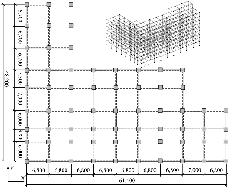
Figure 16. Plan view and three-dimensional model of the hospital building used for the case study (Unit: mm).
A finite element model of the building was created in the Open System for Earthquake Engineering Simulation (OpenSees) software (2012). The beams and columns were simulated using non-linear beam-column elements, which were defined as force-based elements with distributed plasticity. Five Gauss-Lobatto integration points were inserted along the length of each element with two at the ends to simulate the formation of plastic hinges. The composite RC cross-sections were conveniently simulated by the fiber formulation. Concrete material with a linearly decaying tensile strength proposed by Hisham and Yassin (1994) was adopted. The input parameters of the confined concrete were determined using Mander's theoretical stress-strain model (Mander et al., 1988). A Giuffre-Menegotto-Pinto uniaxial material model (Menegotto and Pinto, 1973) with isotropic strain hardening was used to model the longitudinal steel rebars. The story mass and the corresponding gravity were uniformly distributed to each beam-column joint and the rigid diaphragm constraint was used for each floor. P-Delta effect was considered for the geometric non-linearity. A Rayleigh damping of 5% was assigned to the first two modes of vibration. The first three fundamental natural periods of the building were 1.2362, 1.1599, and 1.0772 s, respectively. Detailed information can be found in Shang et al. (in press).
The far-field record set that includes 22 records was selected from the Pacific Earthquake Engineering Research Center Next Generation Attenuation (PEER NGA) database (Ancheta et al., 2013) and the criteria suggested by FEMA P695 (2009) were used. These ground motions were adopted to conduct non-linear time history analysis for evaluating the seismic performance of the building. The acceleration response spectra of the selected ground motions are presented in Figure 17.
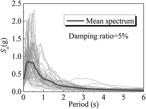
Figure 17. Response spectra of the selected ground motion records.
Fragility Analysis of Grooved Fit Piping Joints
Probabilistic Seismic Demand Model
A probabilistic seismic demand model (PSDM) can be obtained through regression analysis using the computed responses. The relationship between the interstory drift ratio (IDR) of each story and ground motion intensity was estimated using a standard power function, as presented by Li and Ellingwood (2007):
which can be rewritten in the logarithmically transformed space as:
where SD is the conditional median interstory drift ratio demand, a and b are unknown regression coefficients which can be found from linear regression in the log space, and IM is the ground motion intensity measure [Sa(T1) in this study]. A conditional logarithmic standard deviation, βD|IM, was estimated based on the calculated data to consider the uncertainty associated with the demand model (Li and Ellingwood, 2008; Tavares et al., 2012):
where N is the number of simulations and di is the calculated maximum interstory drift ratio. Figure 18 shows the result of the probabilistic seismic demand analysis for first floor of the 10-story building. R2 is the coefficient of determination which can be used to indicate the robustness of the regression. Parameters used to define the probabilistic seismic demand model of the case study building are given in Table 3.
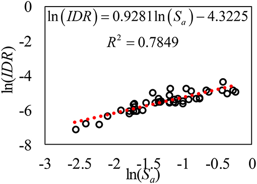
Figure 18. Probabilistic seismic demand model.
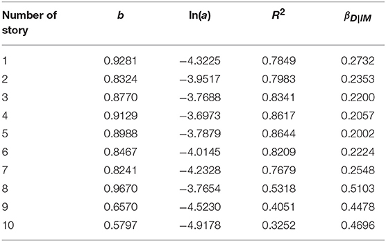
Table 3. Parameters of the probabilistic seismic demand model.
Probabilistic Seismic Fragility Analysis
It is assumed that the pipe joints of vertical pipes are installed at the ends of the pipe, nearly at the same level of the floor slab, as presented in Figure 19. We assumed that the rotation on vertical pipes imposed by building deformation (drift) is only concentrated at end joint rotations, so that the joint rotation is equal to the interstory drift ratio (IDR) (Soroushian et al., 2014a). The following assumptions have been made in this study:
(1) flexural and shear deformation of pipe segments is negligible;
(2) the top and bottom of vertical pipe at each floor is fixed by solid sway braces.
With the developed PSDM of the interstory drift ratio of each story and the capacity as defined by component fragility curve (section Experimental Fragility Analysis of Grooved Fit Joints), the exceedance probability that the pipe joint demand (D) would be larger than the capacity (C) at a given earthquake intensity measure was computed by Equation (10) for the three damage states. It can be rewritten as Equation (11) by substituting the demand median SD in the form of Equation (8) (Tavares et al., 2012):
Figure 20 shows fragility curves of grooved fit joints (DN150) used for vertical pipes using Sa(T1) as an intensity measure, where Fi (i = 1,2,…,10) represents the fragility curve of i-th floor. The damage probability of grooved fit joints (DN150) used for the vertical pipe under 0.07, 0.20 and 0.40 g [corresponding Sa(T1) are 0.0498, 0.1424, and 0.2847 g] corresponding to the service level earthquake (SLE), design-basis earthquake (DBE), and maximum considered earthquake (MCE) in the Chinese codes (GB50011–2010) is nearly zero. The large deformation capacity of the improved grooved fit joints would ensure the functionality of fire protecting after a rarely occurred earthquake.
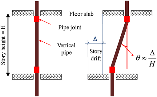
Figure 19. Schematic of vertical pipe and pipe joints (Soroushian et al., 2014a).
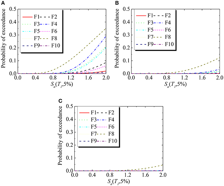
Figure 20. Fragility curves of grooved fit joints (DN150) of the pure frame (A) DS1 (B) DS2 (C) DS3.
Summary and Discussions
Monotonic and reverse cyclic testing were conducted on 12 grooved fit joints to evaluate their seismic performance. Three damage states were defined and fragility curves for different grooved fit piping joints were developed based on test results. A probabilistic seismic fragility analysis was conducted on a 10-story frame building equipped with DN150 vertical stem pipeline as the fire sprinkler system. Major findings are as follows:
(1) The test results indicate that the fracture of grooved fitting and the pull-out of pipes from the grooved fitting are the major damage patterns. Although slight abrasion and wear were observed on the contact surface between the galvanized steel pipe and the grooved fitting, they would not result in significant leakage.
(2) All improved joints exhibited significantly large rotational capacities ranging from 0.054 to 0.274 rad before the massive leakage occurred. At the 50% exceedance probability, the rotation capacity corresponding to the leakage limit state is 0.0642, 0.0891, and 0.2174 rad for the DN150 elbow joint, the DN150 connection of Tee joint, and the DN80 connection of Tee joint, respectively.
(3) Probabilistic seismic fragility analysis of vertical piping system in a 10-story building was conducted based on probabilistic seismic demand analysis. Failure probability of DN150 grooved fit joints is quite small even under maximum considered earthquake, implying the fire protection would be functional.
This is a preliminary study on the functionality of fire sprinkler system, as part of the series studies of seismic resilience on important buildings. More realistic boundary conditions and configurations of this system shall be considered in the future. The damages, such as the pounding damage between the piping system and nearby objects, anchorage damage of fasteners, and anchors that connect the piping system to structural members, failure of pipe hangers, breaking of sprinkler heads, should be included to comprehensively investigate the seismic vulnerability of sprinkler piping systems in different types of buildings.
Author Contributions
TW is in charge of the whole project including tests and analysis. QS completed the experiment and analysis. XC helped to prepare the test. JL helped to complete the fragility analysis.
Funding
This research was funded by the Scientific Research Fund of Institute of Engineering Mechanics, China Earthquake Administration (Grant No. 2017A02), the National Natural Science Foundation of China (Grant Nos. 51378478, 51678538), and the Heilongjiang Provincial Natural Science Fund for Distinguished Young Scholars (Grant No. JC2018018). Any opinions, findings, and conclusion or recommendation expressed in this paper are those of the authors and do not necessarily reflect the views of the sponsors.
Conflict of Interest Statement
The authors declare that the research was conducted in the absence of any commercial or financial relationships that could be construed as a potential conflict of interest.
References
Ancheta, T., Darragh, R., Stewart, J., Seyhan, E., Silva, W., Chiou, B., et al. (2013). PEER NGA-West2 Database, Technical Report PEER 2013/03. Pacific Earthquake Engineering Research Center, Berkeley, CA.
Antaki, G., and Guzy, D. (1998). Seismic testing of grooved and threaded fire protection joints and correlation with NFPA seismic design provisions. ASME Proc. Pressure Vessels Piping Division 364, 69–75.
Ayres, J. M., and Ezer (1996). Associates Inc. Northridge Earthquake Hospital Water Damage Study, Office of Statewide Health Planning and Development. Sacramento, CA.
Blasi, G., Aiello, M. A., Maddaloni, G., and Pecce, M. R. (2018). Seismic response evaluation of medical gas and fire-protection pipelines' Tee-Joints. Eng. Struct. 173, 1039–1053. doi: 10.1016/j.engstruct.2018.07.045
Chock, G. (2006). Preliminary Observations on the Hawai'i Earthquakes of October 15. EERI Special Earthquake Report.
Dhakal, R. P., Pourali, A., Tasligedik, A. S., Yeow, T. Z., Baird, A., Macrae, G. A., et al. (2016). Seismic performance of non-structural components and contents in buildings: an overview of NZ research. Earthquake Eng. Eng. Vibration 15, 1–17. doi: 10.1007/s11803-016-0301-9
Dillingham, J. S., and Goel, R. K. (2002). Dynamic Properties of Fire Sprinkler Systems, Department of Civil and Environmental Engineering. California Polytechnic State University, San Luis Obispo, CA.
FEMA 461 (2007). Interim Protocols for Determining Seismic Performance Characteristics of Structural and Nonstructural Components Through Laboratory Testing. Washington, DC: Federal Emergency Management Agency.
Filiatrault, A., and Sullivan, T. (2014). Performance-based seismic design of nonstructural building components: the next frontier of earthquake engineering. Earthquake Eng. Eng. Vibration 13, 17–46. doi: 10.1007/s11803-014-0238-9
Fleming, R. P. (1998). Analysis of Fire Sprinkler Systems Performance in the Northridge Earthquake. National Institute of Standards and Technology. NIST-GCR-98–736.
GB 50011-2010 (2010). Code for Seismic Design of Buildings. Beijing: China Architecture and Building Press, 2010 (in Chinese).
GB 50261-2005 (2005). Code for Installation and Commissioning of Sprinkler Systems. Beijing: China Planning Press.
Global, F. (2001). Nisqually (Seattle, Wash., USA) Earthquake. Understanding the Hazard, Report P0042, FM Global.
He, S. W., Qu, Z., and Ye, L. H. (2018). Experiment study on the seismic fragility of water supply pipelines in buildings. China Civil Eng. J. 51, 11–19. doi: 10.15951/j.tmgcxb.2018.10.002
Hisham, M., and Yassin, M. (1994). Nonlinear Analysis of Prestressed Concrete Structures Under Monotonic and Cycling Loads. PhD dissertation, University of California, Berkeley.
Jochen, C., Peng, Z., and Magistrale, H. (2018). Seismic performance of chlorinated polyvinyl chloride sprinkler pipes. Earthquake Spectra 34, 1497–1513. doi: 10.1193/091217EQS181M
Ju, B. S. (2011). Seismic Fragility of Piping System. Ph.D. Dissertation, Department of Civil Engineering, North Carolina State University, Raleigh, North Carolina.
LeGrone, P. D. (2004). “An analysis of fire sprinkler system failures during the Northridge earthquake and comparison with the seismic design standard for these systems,” in 13th World Conference on Earthquake Engineering Conference Proceedings (Vancouver, BC).
Li, Q., and Ellingwood, B. (2007). Performance evaluation and damage assessment of steel frame buildings under mainshock-aftershock earthquake sequence. Earthquake Eng. Struct. Dyn. 36, 405–427. doi: 10.1002/eqe.667
Li, Q., and Ellingwood, B. (2008). Damage inspection and vulnerability analysis of existing buildings with steel moment-resisting frame. Eng. Struct. 30, 338–351. doi: 10.1016/j.engstruct.2007.03.018
Mander, J. B., Priestley, M. J. N., and Park, R. (1988). Theoretical stress-strain model for confined concrete. J. Struct. Eng. 114, 1804–1826.
McKevitt, W. E., Timler, P. A. M., and Lo, K. K. (1995). Nonstructural damage from the Northridge earthquake. Canad. J. Civil Eng. 22, 428–437.
Meide (2016). Ductile Iron Grooved Fittings and Couplings. Jinan: JINAN Meide CASTING CO., LTD. Available online at: http://www.meide-casting.com
Menegotto, M., and Pinto, P. (1973). “Method of analysis for cyclically loaded RC plane frames including changes in geometry and non-elastic behavior of elements under combined normal force and bending,” in Symposium on Resistance and Ultimate Deformability of Structures Acted on by Well-defined Repeated Loads, IABSE Reports 13, Lisbon.
Miranda, E., Mosqueda, G., Retamales, R., et al. (2012). Performance of nonstructural components during the 27 february 2010 chile earthquake. Earthquake Spectra 28, S453–S471. doi: 10.1193/1.4000032
Mizutani, K., Kim, H., Kikuchihara, M., Nakai, T., Nishino, M., and Sunouchi, S. (2012). “The damage of the building equipment under the 2011 Tohoku pacific earthquake,” in 9th Interna-tional Conference on Urban Earthquake Engineering and 4th Asia Conference on Earthquake Engineering, Tokyo Institute of Technology. Tokyo.
Open System for Earthquake Engineering Simulation (OpenSees) (2012). OpenSees Web Page. University of California, PEER, Berkeley, CA. Available online at: http://opensees.berkeley.edu/index.php
OSHPD (1995). The Northridge Earthquake: A report to the hospital building safety board on the performance of hospitals. Office of Statewide Health Planning and Development, Facilities Development Division, Sacramento, CA.
Porter, K., Kennedy, R., and Bachman, R. (2007). Creating fragility functions for performance based earthquake engineering. Earthquake Spectra 23, 471–489. doi: 10.1193/1.2720892
Reedlunn, B., Daly, S. Jr., L., H., and Shaw, Z. J. (2011). Tips and tricks for characterizing shape memory wire part 5: full-field strain measurement by digital image correlation. Exp. Tech. 37, 62–78. doi: 10.1111/j.1747-1567.2011.00717.x
Shang, Q. X., Li, J. C., and Wang, T. (2018). Experimental study on seismic performance of grooved fit joints of fire sprinkler piping system. (in Chinese). Earthquake Eng. Eng. Dyn. 6, 86–94. doi: 10.13197/j.eeev.2018.06.86.shangqx.011
Shang, Q. X., Wang, T., and Li, J. C. (in press). Seismic fragility of flexible pipeline connections in a base isolated medical building. Earthquake Eng. Eng. Vibration.
Soroushian, S., Maragakis, E. M., and Zaghi, A. E. (2014a). “Comprehensive Analytical Seismic Fragility of Fire Sprinkler Piping Systems,” in Technical Report MCEER-14-0002, San Diego, CA.
Soroushian, S., Zaghi, A. E., and Maragakis, E. Â. (2014b). Seismic fragility study of displacement demand on fire sprinkler piping systems. J. Earthquake Eng. 18, 1129–1150. doi: 10.1080/13632469.2014.917059
Soroushian, S., Zaghi, A. E., and Maragakis, M. (2015a). Analytical seismic fragility analyses of fire sprinkler piping systems with threaded joints. Earthquake Spectra 31, 1125–1155. doi: 10.1193/083112EQS277M
Soroushian, S., Zaghi, A. E., Maragakis, M., et al. (2015b). Seismic fragility study of fire sprinkler piping systems with grooved fit joints. J. Struct. Eng. 141:04014157. doi: 10.1061/(ASCE)ST.1943-541X.0001122
Steinbrugge, K. (1982). Earthquakes, Volcanoes, and Tsunamis An Anatomy of Hazards. Report of Skandia America Group.
Tatarsky, M., and Filiatrault, A. (2019). Seismic response of viscously damped braced thin-wall piping system: a proof-of-concept case study. Bull. Earthquake Eng. 17, 537–559. doi: 10.1007/s10518-018-0447-0
Tavares, D. H., Padgett, J. E., and Paultre, P. (2012). Fragility curves of typical as-built highway bridges in eastern Canada. Eng. Struct. 40, 107–118. doi: 10.1016/j.engstruct.2012.02.019
Tian, Y., Filiatrault, A., and Mosqueda, G. (2014). Experimental seismic fragility of pressurized fire suppression sprinkler piping joints. Earthquake Spectra 30, 1733–1748. doi: 10.1193/111011EQS278M
Tian, Y., Filiatrault, A., and Mosqueda, G. (2015). Seismic response of pressurized fire sprinkler piping systems I: experimental study. J. Earthquake Eng. 19, 649–673. doi: 10.1080/13632469.2014.994147
Keywords: piping system, grooved fit joints, large deformability, quasi-static test, leakage limit state
Citation: Wang T, Shang Q, Chen X and Li J (2019) Experiments and Fragility Analyses of Piping Systems Connected by Grooved Fit Joints With Large Deformability. Front. Built Environ. 5:49. doi: 10.3389/fbuil.2019.00049
Received: 19 December 2018; Accepted: 28 March 2019;
Published: 17 April 2019.
Edited by:
Antonio Formisano, University of Naples Federico II, ItalyReviewed by:
Fabrizio Paolacci, Roma Tre University, ItalyHuseyin Bilgin, Epoka University, Albania
Copyright © 2019 Wang, Shang, Chen and Li. This is an open-access article distributed under the terms of the Creative Commons Attribution License (CC BY). The use, distribution or reproduction in other forums is permitted, provided the original author(s) and the copyright owner(s) are credited and that the original publication in this journal is cited, in accordance with accepted academic practice. No use, distribution or reproduction is permitted which does not comply with these terms.
*Correspondence: Tao Wang, d2FuZ3Rhb0BpZW0uYWMuY24=