 Yajun Jiang
 Sanjay Nimbalkar
- 1Key Laboratory of Transportation Tunnel Engineering, Ministry of Education, Southwest Jiaotong University, Chengdu, China
- 2School of Civil and Environmental Engineering, University of Technology Sydney, Sydney, NSW, Australia
This paper presents a two dimensional finite element (FE) approach to investigating beneficial aspects of geogrids in the railway track. The influences of different factors including the subgrade strength, the geogrid stiffness, the placement depth of geogrid, the effective width of geogrid, the strength of ballast-geogrid interface and the combination of double geogrid layers were investigated under the monotonic loading. The results indicated the role of geogrid reinforcement is more pronounced over the weak compressible subgrade. A stiffer geogrid reduces ballast settlement and produces a more uniform stress distribution along a track. The placement location of a geogrid is suggested at the ballast-sub-ballast interface to achieve better reinforcement results. Although the width of a geogrid layer should be sufficient to cover an entire loaded area, excessive width does not guarantee additional benefits. Higher interface strength between a ballast and a geogrid is beneficial for effective reinforcement. Increasing the number of geogrid layers is an effective way to reinforce the ballast over weak subgrades. The results of the limited cyclic FE simulations revealed the consistency of the reinforcement effect of the geogrids under monotonic and cyclic loads.
Introduction
Ballasted rail tracks progressively deform in vertical and lateral directions, which cause deviations from the desired geometry under repeated traffic loading (Selig and Waters, 1994). A ballast can deteriorate due to the breakage of angular sharp corners under cyclic loading, which accelerates the settlement of a track (Indraratna et al., 2005). The differential settlement of a track reduces the level of safety of the track and causes significant risk to trains. Therefore, track maintenance, including tamping and replacement of ballasts, is periodically conducted to correct geometry faults (Esveld, 2001).
The ballast layer is often contaminated by fouling agents such as downward coal spillage from moving wagons, upward clay migration and internal particle breakage (Nimbalkar et al., 2012; TolouKian et al., 2018). This leads to rapid deterioration along with settlements often combined by the lateral spread owing to less lateral restraints (Nimbalkar and Indraratna, 2016; Sun et al., 2017). The regular track maintenance operations are needed which attracts huge funds to maintain track in operations (Sadeghi et al., 2018, 2019). In recent years, studies have focused on the improving confining pressure on a ballast to reduce the settlement of railway tracks during operation (Indraratna et al., 2005, 2013; Lackenby et al., 2007).
Various types of geosynthetics have been extensively employed in practice to improve or modify the behaviors of soil, aggregate and other construction materials in geotechnical engineering (Ghosh and Madhav, 1994; Moghaddas-Nejad and Small, 1996; Haeri et al., 2000; Raymond and Ismail, 2003; Palmeira, 2009; Indraratna et al., 2015). In current practical applications, the insertion of a geosynthetics layer in track substructures is an effective and economic method for increasing the confining pressures on a ballast and conducting the renewal of a track (Amsler, 1986; Raymond, 1999; Lieberenz and Weisemann, 2002; Indraratna and Salim, 2003; Fernandes et al., 2008; Indraratna et al., 2010, 2014a).
Geogrids have been utilized to reinforce railway track substructures since 1980s (Coleman, 1990). Previous laboratory studies (Bathurst and Raymond, 1987; Gobel and Weisemann, 1994; Raymond, 2002; Shin et al., 2002; Brown et al., 2007; Indraratna et al., 2011a) and field studies (Indraratna et al., 2010, 2014a,b) have demonstrated the successful application of geogrids in track reinforcement. Limited numerical simulations have been conducted to analyze the reinforcement mechanism of geogrids in railway tracks (Indraratna et al., 2007; Jirousek et al., 2010; Chen et al., 2012; Indraratna and Nimbalkar, 2013). The discrete element models are usually applied to capture the particle-scale mechanism and interface behavior using geosynthetics (Han et al., 2011; Tutumluer et al., 2012; Ngo et al., 2017; Gao and Meguid, 2018). However, these models are not able to capture the overall track response (Li et al., 2018). A generally accepted method or standard for the design or renewal of railway tracks with geogrids is lacking.
In contrast to laboratory and field investigations, the numerical method is a convenient and economical method for investigating the mechanical behaviors of geogrids and the surrounding components of track substructures. Thus, the main objective of this study was to employ a finite element (FE) model to improve the comprehensive understanding of the geogrid reinforcement mechanisms of railway ballasts. Influencing factors such as the subgrade strength, the geogrid stiffness, the placement depth of a geogrid layer inside a ballast, the effective width of a geogrid layer, the strength reduction factor of the geogrid/ballast interface and the effect of double geogrid layers were considered. Subsequently, the reinforcement performance of a geogrid and the influences of these factors were illustrated based on the simulation results. The simulation results of cyclic loading was compared with field data to explore ballast behavior under repeated train loads.
Establishment of FE Model
The FE method has been proven to be a useful and effective method for analyzing the behaviors of track structures (Selig and Waters, 1994; Esveld, 2001). The authors have performed a series of fundamental numerical simulations, which focused on the behaviors of ballasts with and without geosynthetics, using plane-strain track models (Indraratna et al., 2007; Indraratna and Nimbalkar, 2013). Thus, this study can be considered as an extension of the authors' previous studies.
Modeling
PLAXIS has demonstrated its success in the limit analysis of geotechnical problems (PLAXIS, 2007). In this study, a two-dimensional plane-strain finite element model of a composite multi-layer track system, including the rail, sleeper, ballast, sub-ballast and subgrade (as shown in Figure 1), was numerically simulated using PLAXIS2D.
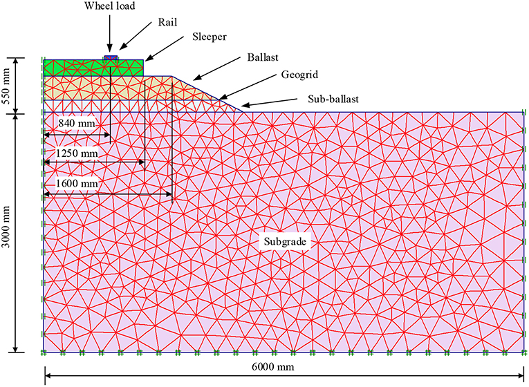
Figure 1. Finite element mesh discretization of a rail track substructure.
Only half of the rail track was simulated in the model due to the symmetry of the track. The width and height of the subgrade is 6 and 3 m, respectively. The heights of the sub-ballast, ballast and sleeper are 150, 300, and 200 mm, respectively. The gauge length of the track is 1.68 m, the length of the half sleeper is 1.25 m, and the side slope of the rail track embankment is 1:2. The rail is simplified as a rectangle with a width of 160 mm and a height of 50 mm to ensure that the total area is equivalent to the Australian 60 kg/m rail (Doyle, 1980).
The nodes along the bottom boundary of the section were considered to be standard and fixed. The left and right boundaries were restrained in horizontal directions to represent smooth contact in the vertical direction. The rail was restrained in the horizontal direction to simulate the connection between the sleeper and the rail.
The geogrid in the model was created with the Geogrid Element provided by PLAXIS2D, and the interface elements along each side of the geogrid were created to simulate the interaction relationship between ballast and geogrid (PLAXIS, 2007).
The geogrid was initially placed at the ballast/sub-ballast interface in the model; however, different placement locations were also considered at different phases during the simulations.
Parameters
Material Parameters of Main Components
The material parameters and constitutive models that were employed for the main components of the model are listed in Table 1, and the ballast was simulated using a hardening soil model, which is suitable to describe the behavior of a ballast under wheel loading (Indraratna et al., 2012; Indraratna and Nimbalkar, 2013). The parameters are chosen based on the actual measurement data of ballast behavior as observed in the laboratory tests (Indraratna and Nimbalkar, 2013) and field trials (Nimbalkar and Indraratna, 2016). The numerical model is an extension of previous works (Indraratna and Nimbalkar, 2011; Nimbalkar and Indraratna, 2014) and results are in agreement with these numerical studies. The accuracy and reliability of the model is thus demonstrated.
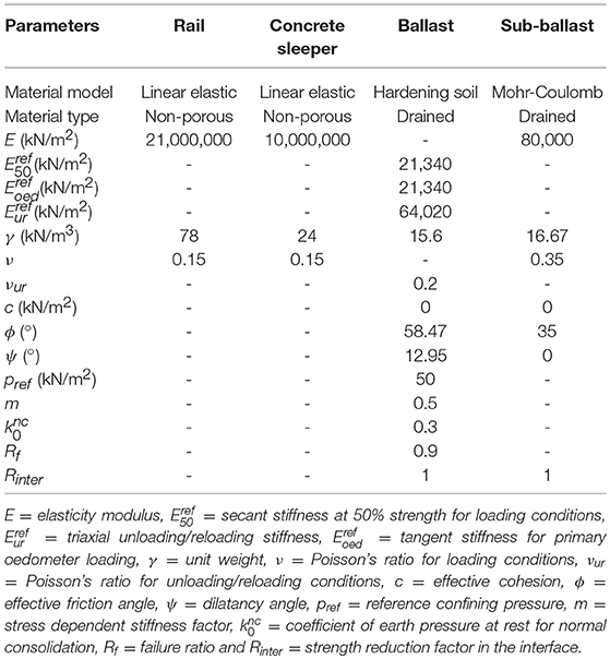
Table 1. Material parameters and constitutive models in the finite element analysis (Indraratna et al., 2012).
Subgrade Strength
The strength parameters of different typical subgrades, including poor, fair, good and rocky subgrades, are listed in Table 2; they were considered in the simulations to explore the influence of subgrade strength.
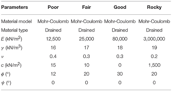
Table 2. Material parameters and constitutive models for subgrades (adapted from Khordehbinan, 2009).
Axial Geogrid Stiffness
The axial geogrid stiffness always differs by the factors of the aperture dimensions, the tensile strength of the manufacture material and the rib thickness. Thus, the EA values of the geogrids in the simulations were varied for comparison purposes (i.e., EA = 275, 525, 775, 1,025, and 1,275 kN/m).
Placement Depth of Geogrid Layer
The placement depth of the geogrid layer inside the ballast was initially set at the ballast/sub-ballast interface in the model, i.e., 300 mm below the sleeper. Other placement depths inside the ballast were also considered in the simulations (i.e., 50, 100, 150, 200, and 250 mm below the sleeper).
Effective Width of Geogrid Layer
The effective width of the geogrid layer was initially set to 2.2 m when the geogrid layer was placed at the ballast/sub-ballast interface in the model. To investigate the influence of width, effective widths of the geogrid layer of 0.4, 0.8, 1.2, 1.6, and 2.0 m were also considered.
Strength Reduction Factor of Geogrid Interfaces
The strength reduction factor Rinter defines the behaviors of the interfaces between the geogrid and the adjacent components. This parameter is influenced by the complex interaction relationship between the aperture size of the geogrids, the mean particle size of the soil materials, the physical properties of the geogrids and the mechanical behaviors of the soils (Goodhue et al., 2001; Brown et al., 2007; Indraratna et al., 2012). Therefore, the values of Rinter, including 0.4, 0.6, 0.8, and 1.0 (rigid), were considered to investigate the influence of the interaction between the geogrid and the ballast on the reinforcement effect.
Load Determination
The equivalent dynamic wheel load Pd is empirically expressed as the static wheel load Ps times the dynamic impact factor ø (Jeffs and Tew, 1991; Sun et al., 2015). The American Railroad Engineering Association (AREA) formula was applied in the calculation of the impact factor ø (Jeffs and Tew, 1991)
where v = vehicle speed (km/h) and D = wheel diameter (mm). A Pd value of 178.71 kN was considered to simulate a train speed of 80 km/h and a wheel diameter of 970 mm.
Calculation Cases
The following factors were investigated in this study: the subgrade strength, the geogrid stiffness (EA), the placement depth of the geogrid layer inside the ballast (D), the effective width of the geogrid layer (B), the strength reduction factor of the geogrid/ballast interfaces (Rinter) and the effect of double geogrid layers. To avoid the complex interaction effects among the factors, the simulation investigation was divided into six calculation cases. Details of the parameter settings of these factors for each case are presented in Table 3.
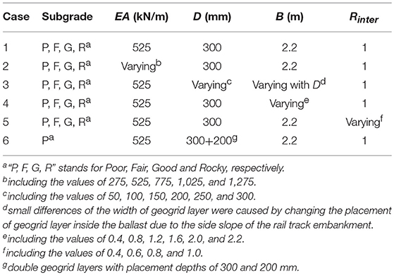
Table 3. Parameter setting for the monotonic loading cases.
Analysis and Discussion of Monotonic Loading Results
The reinforcement effect of a geogrid can be evaluated by the reinforcement rate R, which was calculated by
where Stu and Str = the settlement on the top of ballast (below the rail) without and with geogrid reinforcement, and ΔSt = the settlement difference on the top of the ballast with the geogrid reinforcement.
Subgrade Strength
The results for Stu, Str, ΔSt, and R of Case 1 are presented in Table 4. Improved geogrid reinforcement performance was observed over the weaker subgrades, which can be explained by the geogrid reinforcement mechanisms. The subgrade settlement determined the deformations of other track components and subsequently mobilized the tensile/interlocking capacity of the geogrid (Kwon and Penman, 2009).
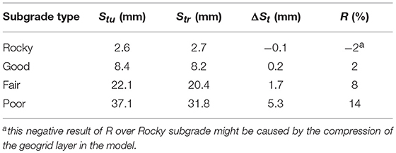
Table 4. Results of Case 1 with respect to the factor of subgrade strength.
To illustrate the influence of subgrade strength, the vertical deformations of the subgrade surface over the different subgrades in the reinforced models in Case 1 are plotted in Figure 2. The maximum axial forces on the horizontal direction in the geogrids (Fag)max over different subgrades in the reinforced models are plotted in Figure 3. As expected, the larger surface deformation of the subgrade appeared over the weaker subgrade. Consequently, the different axial forces in geogrids were induced by the corresponding subgrade deformations. The different extents of the interlock, confinement and load distribution effects were subsequently observed. Therefore, the subgrade strength is an important factor of geogrid reinforcement performance. Better geogrid reinforcement performance can be expected over the weak subgrades due to the greater compressibility of the weak subgrades.
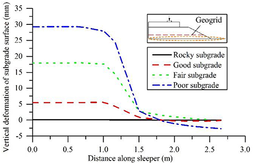
Figure 2. Vertical deformations of subgrade surfaces over different subgrades in the reinforced models (Case 1).
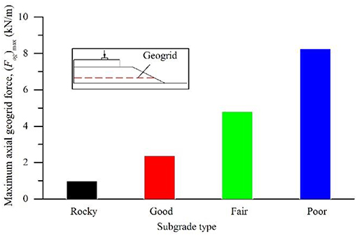
Figure 3. Maximum axial forces in geogrids over different subgrades in the reinforced models (Case 1).
Geogrid Stiffness
The results for R and (Fag)max of Case 2 are plotted in Figure 4. An approximately linear relationship between R and EA was observed, i.e., increasing the geogrid stiffness increased the enhanced reinforcement rate. (Fag)max almost linearly increased by increasing EA. Subsequently, additional reductions of the deformations and more uniform stress distributions in the surrounding soil layers can be expected with a stiffer geogrid. This may be attributed to the fact that the geogrid with a higher stiffness value produced greater axial force and less tensile deformations under the same vertical load. Consequently, the reinforcement effects were enhanced due to the higher geogrid stiffness. The influence of subgrade strength on the geogrid reinforcement was observed, i.e., better reinforcement effects were achieved over the weaker subgrades. In addition to the geogrid stiffness, the performance of the geogrid reinforcement is also dependent on the subgrade strength.
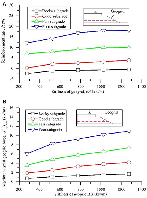
Figure 4. Reinforcement rate and maximum axial force in geogrids with respect to the factor of geogrid stiffness over different subgrades (Case 2): (A) reinforcement rate; (B) maximum axial geogrid force.
Placement Depth of Geogrid Layer
The results for R and (Fag)max of Case 3 are plotted in Figure 5. The reinforcement rates over the fair and poor subgrades increased with an increase in the placement depth of the geogrid layer inside the ballast. The peak values of the reinforcement rates over poor and fair subgrades occurred within the placement depth range of 250–300 mm, which is located near the bottom of the ballast layer. (Fag)max increased with an increase in D, and the maximum value of (Fag)max was obtained over the poor subgrade due to the maximum subgrade deformation. Therefore, this study recommends that geogrids should be placed near the bottom of a ballast, which is consistent with practical solutions in the field, in which the geogrid layer is usually placed at the ballast/sub-ballast interface to protect geogrids from damage due to tamping maintenance. Some research results also suggested that the optimum placement depth for the geosynthetics inside a ballast should be varied for different conditions (Coleman, 1990). Brown et al. (2007) suggested the bottom of a ballast layer as an optimum placement location for geogrids.
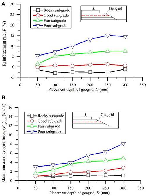
Figure 5. Reinforcement rate and maximum axial force in geogrids with respect to the factor of placement depth of geogrid layer (Case 3): (A) reinforcement rate; (B) maximum axial geogrid force.
Effective Width of Geogrid Layer
The results for R of Case 4 are plotted in Figure 6A. The reinforcing function of the geogrid over fair and poor subgrades was not activated until the effective width of the geogrid layer exceeded 1.2 m, which was almost equal to the length of the half model sleeper. Subsequently, higher reinforcement rates were observed in the width range of 1.6–2.0 m for the geogrid layer. However, the peak value of the reinforcement rate was not observed at the maximum width of 2.2 m. Therefore, a sufficient width of the geogrid layer is essential for the reinforcement; however, excessive width does not provide significant benefit.
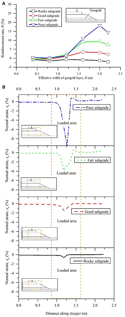
Figure 6. Reinforcement rate of geogrids with respect to the factor of effective width of geogrids (Case 4) and normal strain on the sub-ballast surface in unreinforced models over different subgrades: (A) reinforcement rate; (B) normal strain and loaded area on the sub-ballast surface in unreinforced models.
To investigate the loaded area of the location where the geogrid was placed, the normal strains (εn) on the top of the sub-ballast over different subgrades of unreinforced models are plotted in Figure 6B. The loaded areas on the top of the sub-ballast over different subgrades were almost located in the depth range of 1.0–1.5 m under the unreinforced conditions. The excessive width of the geogrid layer cannot provide additional benefits when the width extends beyond the range of the loaded area as the reinforcement benefit by interlock was generated within the loaded area and the geogrid did not have to be anchored beyond the loaded area (Guido et al., 1987).
Strength Reduction Factor
The results for R of Case 5 are plotted in Figure 7A. The distinct trend is an increase in the reinforcement performance with an increase in Rinter. A constant value of the reinforcement rate was attained when Rinter varied from 0.8 to 1.0. As expected, a larger Rinter produced better performance. Minor settlement reduction was observed over the rocky subgrade and the good subgrade. The geogrid reinforcement cannot be employed in the railway ballast over the stiff subgrades, which is consistent with field measurements that indicate an increased effectiveness of the reinforcing geogrids on the soft subgrade (Indraratna et al., 2014a).
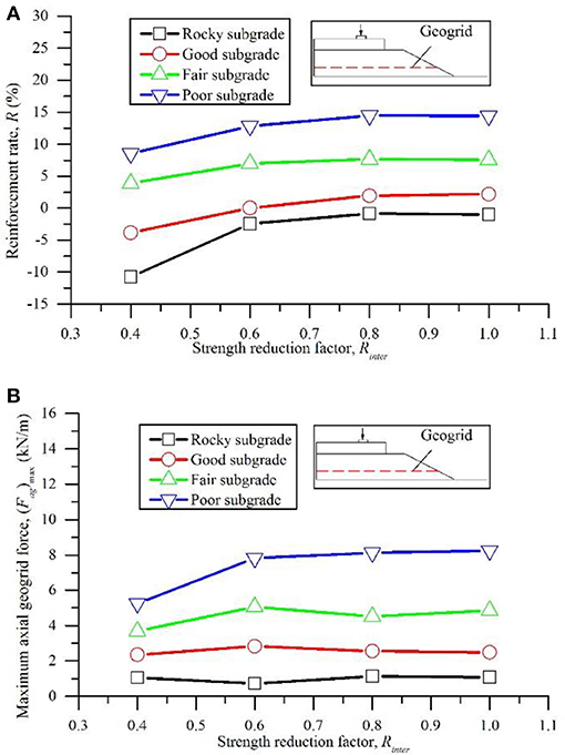
Figure 7. Reinforcement rate and maximum axial force in geogrids with respect to the factor of strength reduction factor (Case 5): (A) reinforcement rate; (B) maximum axial geogrid force.
The value of Rinter influences the interaction between a geogrid and a ballast. Generally, tighter interaction between a geogrid and a ballast may produce a higher axial force in the geogrid. Thus, the (Fag)max values of Case 5 are plotted in Figure 7B to show the influence of Rinter. The values of (Fag)max over the rocky and good subgrades did not significantly change, i.e., the reinforcement effect of the geogrid over these stiff subgrades can be disregarded. Thus, the variation in Rinter did not provide any pronounced improvement of the settlement of the ballast. Distinct increments of (Fag)max were not observed when Rinter varied in the range of 0.6–1.0 over the poor and fair subgrades. This trend is consistent with the trends of the reinforcement rates that are presented in Figure 10, which reveals that the Rinter may have less influence on the reinforcement performance than the remaining factors and additional laboratory tests and field investigations are needed to comprehensively understand the interaction between a geogrid and a ballast.
Double Geogrid Layers
The poor subgrade conditions were considered in Case 6. The corresponding reinforcement rates for each single geogrid layer and the double layers are plotted in Figure 8A. In this figure, “S” denotes the condition of a single geogrid layer in the model; “D” denotes double layers; and “200” and “300” denote the placement depth of the geogrid layers inside the ballast. Better reinforcement performance was observed when the geogrid layer was placed at the ballast/sub-ballast interface when the single geogrid layer was considered in the simulation. The reinforcement rate increased with an increase in geogrid stiffness. These observations are consistent with Figures 4, 5. However, better reinforcement performance was achieved by the double geogrid layers. Thus, an increase in the number of geogrid layers is an effective method for reinforcing the ballast over weak subgrades besides increasing the geogrid stiffness.
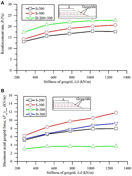
Figure 8. Reinforcement rate and maximum axial force in geogrids with respect to the factor of geogrid layers (Case 6): (A) reinforcement rate; (B) maximum axial geogrid force.
The (Fag)max values of Case 6 are plotted in Figure 8B. The value of (Fag)max in the geogrid of “S-300” was larger than the value of (Fag)max in the geogrid of “S-200,” which indicated that better reinforcement results can be expected when the same geogrid layer was placed at the ballast/sub-ballast interface instead of inside the ballast over the poor subgrade. This observation corresponds to Figure 5 and demonstrates the feasibility of (Fag)max in analyzing the geogrid reinforcement effect of a ballast.
As a result of the double geogrid layers, the reinforcement rate significantly increased. However, the reductions of (Fag)max in each geogrid layer of “D-200” and “D-300” are distinct compared with the reductions of (Fag)max in each geogrid layer of “S-200” and “S-300.” As both of the geogrid layers contributed to the load bearing, the axial forces in each geogrid layer reduced under the same loading, which is also beneficial for the load bearing capacity of the ballast and the geogrids. Thus, double or multiple geogrid layers are more efficient for the reinforcement of a ballast if cost is not considered.
Comparison of Field Behavior With Numerical Predictions
Modeling of Cyclic Loading Simulation
The calculation results of the monotonic loading revealed no distinct enhancements of the reinforcement effects over rocky and good subgrades and the possibility of collapsing failure for the poor subgrade under long-term repeated loads due to the relatively weak strength. Therefore, the track model over the fair subgrade was adopted in the cyclic loading to investigate the reinforcement effect of the geogrid under repeated train loads.
The sinusoidal cyclic load (as shown in Figure 9) was applied. The loading frequency was set to 15 Hz to simulate a train travel speed of 80 km/h (Indraratna et al., 2007). The minimum value of cyclic load was set to zero because the overburden pressure caused by the rail-sleeper assembly was already considered in the gravity generation by PLAXIS. The peak value of the cyclic load was set to 125 kN, which was equivalent to Ps, as the impact caused by the different train travel speeds was already considered in the simulation by the loading frequency. The maximum loading number of cyclic load was 100,000 as the ballast usually enters the stable zone and the settlement of the ballast insignificantly changed after 100,000 cycles (Shin et al., 2002; Indraratna and Nimbalkar, 2013).
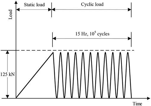
Figure 9. Cyclic loading details.
The geogrid stiffness of 525 kN/m, which was adopted in the cyclic simulation, was obtained from the actual mechanical properties of the biaxial geogrid with an aperture size of 40 mm (Indraratna et al., 2007). Cubical tests by Indraratna and Nimbalkar (2013) also reported an EA of 360 kN/m for a biaxial geogrid with an aperture size of 40 mm. The conditions of the unreinforced track model, the track models reinforced by a single geogrid layer (at the ballast/sub-ballast interface) and reinforced by two geogrid layers (similar to Case 6 in Table 3, i.e., D = 200 and 300 mm), were considered in the simulation.
Results of Cyclic Loading Simulation
The calculation results of Stu, Str and R during the 100,000 load cycles are plotted in Figure 10 including the result of load cycle of 1, 10, 100, 1,000, 10,000, 50,000, and 100,000. The settlement on the top of the ballast layer kept increasing during loading. The stable zone of the unreinforced track model cannot be observed within the 100,000 load cycles. Conversely, the settlement on the top of the ballast layer of the track model, which was reinforced by the single geogrid layer, attained a constant value after 10,000 load cycles. Better reinforcement performance is observed under the conditions of the track model that was reinforced by double geogrid layers, and a very slight settlement difference occurred during loading.
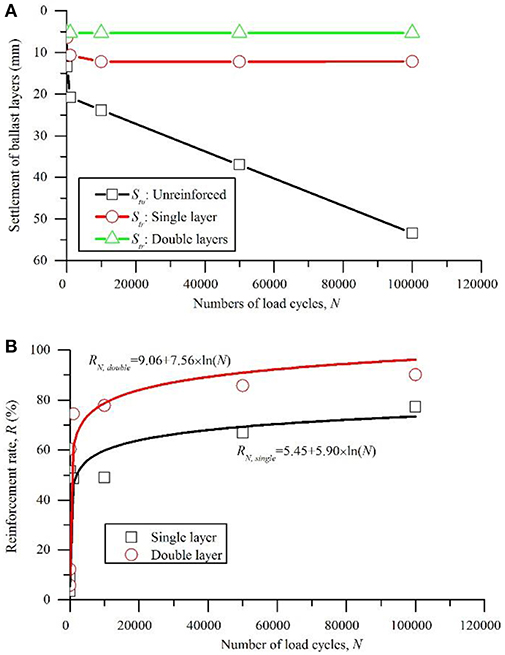
Figure 10. Results of cyclic loading: (A) settlement of ballast layer over fair subgrade; (B) reinforcement rate of single and double layers of geogrids.
The logarithmic trend lines for the two series of reinforcement rates are shown in Figure 10B, and the regression equations are displayed in Figure 10B. Indraratna et al. (2011b) suggested a logarithmic equation for determining the rail track vertical deformation based upon the laboratory findings
where SN is the settlement of the ballast accumulated after N load cycles, c is the settlement after the first load cycle, and d is an empirical constant that is dependent on the initial density, ballast and reinforcement type and moisture content. The simulation results in this study indicate that the reinforcement rate of the geogrid can be described by the similar equation
where RN is the reinforcement rate of the geogrid layers after N load cycles and a and b are the empirical constants that depend on the mechanical properties of the ballast, the subgrade strength, the geogrid stiffness and the number of geogrid layers.
Comparison With Field Data
The simulation results of the cyclic loading is compared with the measured data from a field trial at a site near Bulli in New South Wales, Australia (Indraratna et al., 2010). The settlements under the rail at the section of the fresh ballast with and without geocomposite reinforcement during the first 120,000 load cycles are plotted in Figure 11A. The reinforcement rate of the geocomposite, its logarithmic trend line and the regression equation are displayed in Figure 11B.
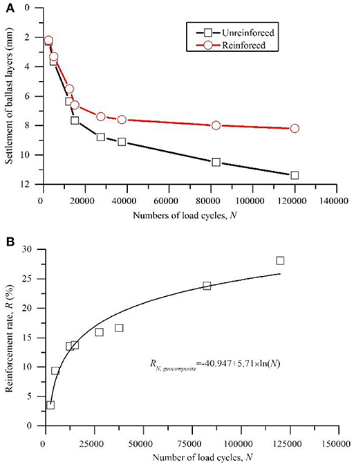
Figure 11. Measured settlement data of the fresh ballast sections at the site near Bulli, NSW, Australia (modified after Indraratna et al., 2010): (A) settlement of the ballast layers with and without geocomposite reinforcement; (B) reinforcement rate of geocomposite.
The comparison of Figure 10 with Figure 11 indicates that the simulation results for the ballast settlement of the unreinforced track over the fair subgrade was relatively larger than the field measurement data. The reinforcement rates for the geogrid layers, which were obtained by the cyclic loading simulations, were more pronounced than the field measurement data. This finding can be explained by the different mechanical properties of the track components, the physical properties of the geosynthetics (the EA value of the geocomposite was approximately 390 kN/m according to Indraratna and Nimbalkar, 2013) and the cyclic parameters of the train loads between the simulations and the field conditions. Thus, additional studies are needed to improve the understanding of the complex relationship between the behavior of a ballast and these factors.
However, similar trends of the reinforcement rates for the geosynthetics are shown in Figures 10, 11, i.e., both the results of the cyclic loading simulations and the field measurements can be successfully described by Equation (4). The parameters a and b in Equation (4) should be varied in every case due to the variation in the mechanical properties of the ballast, the subgrade strength, the geogrid stiffness and the number of geogrid layers. The results indicate the successful application of PLAXIS for simulating and predicting the behaviors of reinforced railway tracks under cyclic loads.
The double geogrid layers were more effective than the single geogrid layer and were beneficial for the load bearing capacity of the ballast and geogrids. The simulation results of the monotonic loading indicate that double or multiple geogrid layers are more efficient for the reinforcement of a ballast if cost is not considered.
Limitations of this Study
The variations of the parameters of subgrade strength were considered in the simulations, which revealed the important role of subgrade in the reinforcement of geogrids. However, the effect of the strength parameters and the constitutive models of ballast and sub-ballast warrant evaluation. The reduction in the degradation of the ballast aggregates caused by the confinement of the geogrids has not been considered.
The strength reduction factor Rinter is influenced by the complex relationship between the aperture size of geogrids, the mean particle size of a ballast, the physical properties of geogrids and the mechanical behaviors of a ballast. Therefore, additional experimental research is needed to correctly define the behaviors of the interfaces in the simulations.
A complex relationship exists between the ballast behavior and cyclic loads. The degradation and breakage of a ballast were not considered in the simulation. Therefore, additional studies are needed to investigate the ballast behaviors and the reinforcement effect of geogrids under cyclic loads of varied amplitude and varied frequency. Three-dimensional simulations and Discrete Element Method (DEM) may provide a better understanding of the long-term geogrid reinforcement effects of railway ballast under cyclic train loads.
Conclusions
The FE simulations that were conducted in this study investigated the geogrid reinforcement effect on a railway ballast that was subjected to monotonic loads. The reinforcement mechanisms of a geogrid and the influences of different factors, including the subgrade strength, the stiffness, placement depth and effective width of a geogrid; the strength reduction factor of the interfaces between a geogrid and a ballast; and the combination of double geogrid layers, were discussed based on the numerical simulation results. The following conclusions are obtained from this study:
a) The reinforcement mechanisms of geogrids comprise the interlock, confinement and load redistribution. The interlock is the most important reinforcement mechanism of geogrids. The geogrid reinforcement reduces the lateral deformations of a ballast and provides a more uniform vertical stress distribution in the soil layers.
b) Better reinforcement performance of geogrids was observed over the weak subgrades due to the relatively larger subgrade deformation.
c) A geogrid with higher stiffness produces greater axial force and less tensile extension under the same train load. Consequently, a more uniform load distribution and less vertical deformation in a ballast can be expected.
d) The suggested optimum placement location of a geogrid layer is the ballast/sub-ballast interface. This depth is practical for the application of a geogrid in a railway track and can provide protection for geogrids from damage due to track maintenance.
e) To achieve better reinforcement performance, the width of a geogrid layer should be sufficient to cover the loaded area at the location where the geogrid layer is placed. However, excessive width of the geogrid layer does not provide additional benefits.
f) Generally, a higher value of the strength reduction factor Rinter for the interfaces between the geogrid and the ballast is beneficial to reinforcement performance. However, the effect of Rinter is relatively insignificant compared with the results of the factor of subgrade strength.
g) Additional geogrid layers can provide a better reinforcement effect on the ballast. Thus, increasing the number of geogrid layers is an effective method for reinforcing a ballast over weak subgrades and increasing the geogrid stiffness.
h) The reinforcement rate of the geogrid layers under cyclic loading can be described by a logarithmic equation. However, the parameters in this equation should be varied based on the conditions of each case under different cyclic loads.
Data Availability
All datasets generated for this study are included in the manuscript and/or the supplementary files.
Author Contributions
SN elaborated the paper guidelines and corrected the paper. YJ prepared the paper draft.
Conflict of Interest Statement
The authors declare that the research was conducted in the absence of any commercial or financial relationships that could be construed as a potential conflict of interest.
Acknowledgments
This study was made possible by the 2011 Endeavour Research Award (Endeavour Research Fellowship) from the Australian Government Department of Education, Employment and Workplace Relations (DEEWR), and help from Prof. Buddhima Indraratna and Associate Professor Cholachat Rujikiatkamjorn of University of Wollongong. The authors acknowledge their support.
References
Amsler, P. (1986). “Railway track maintenance using geotextile,” Proceedings of 3rd International Conference on Geotextiles (Vienna), 1037–1041.
Bathurst, R. J., and Raymond, G. P. (1987). Geogrid reinforcement of ballasted track. Transp. Res. Rec. 1153, 8–14.
Brown, S. F., Kwan, J., and Thom, N. H. (2007). Identifying the key parameters that influence geogrid reinforcement of railway ballast. Geotext. Geomemb. 25, 326–335. doi: 10.1016/j.geotexmem.2007.06.003
Chen, C., McDowell, G. R., and Thom, N. H. (2012). Discrete element modelling of cyclicloads of geogrid-reinforced ballast under confined and unconfined conditions. Geotext. Geomemb. 35, 76–86. doi: 10.1016/j.geotexmem.2012.07.004
Coleman, D. M. (1990). “Use of geogrids in railroad track: a literature review and synopsis,” in Miscellaneous Paper GL-90e4. Amana, IA: US Army Engineer District.
Doyle, N. F. (1980). “Railway track design: a review of current practice,” in Occasional Paper no. 35, Bureau of Transport Economics, Canberra, ACT: Commonwealth of Australia.
Fernandes, G., Palmeira, E. M., and Gomes, R. C. (2008). Performance of geosynthetics reinforced alternative sub-ballast material in a railway track. Geosynth. Int. 15, 311–321. doi: 10.1680/gein.2008.15.5.311
Gao, G., and Meguid, M. A. (2018). Effect of particle shape on the response of geogrid-reinforced systems: insights from 3D discrete element analysis. Geotext. Geomemb. 46, 685–698. doi: 10.1016/j.geotexmem.2018.07.001
Ghosh, C., and Madhav, M. R. (1994). Reinforced granular fill-soil system: confinement effect. Geotext. Geomemb. 13, 727–741. doi: 10.1016/0266-1144(94)90060-4
Gobel, C. H., and Weisemann, U. C. (1994). Effectiveness of a reinforcing geogrid in a railway subbase under dynamic loads. Geotext. Geomemb. 13, 91–99. doi: 10.1016/0266-1144(94)90041-8
Goodhue, M., Edil, T., and Benson, C. (2001). Interaction of foundry sands with geosynthetics. J Geotech. Geoenvironmental Eng. 127, 353–362. doi: 10.1061/(ASCE)1090-0241(2001)127:4(353)
Guido, V. A., Knueppel, J. D., and Sweeny, M. A. (1987). “Plate loading tests on geogrid-reinforced earth slabs,” in Proceedings Geosynthetics '87 Conference (New Orleans, LA), 216–225.
Haeri, S. M., Noorzad, R., and Oskoorouchi, A. M. (2000). Effect of geotextile reinforcement on the mechanical behavior of sand. Geotext. Geomemb. 18, 385–402. doi: 10.1016/S0266-1144(00)00005-4
Han, J., Bhandari, A., and Wang, F. (2011). DEM analysis of stresses and deformations of geogrid-reinforced embankments over piles. Int. J. Geomech. 12, 340–350. doi: 10.1061/(ASCE)GM.1943-5622.0000050
Indraratna, B., Biabani, M. M., and Nimbalkar, S. (2015). Behaviour of geocell reinforced subballast subjected to cyclic loading in plane strain condition. J. Geotech. Geoenvironmental Eng. 141, 04014081-1–04014081-16. doi: 10.1061/(ASCE)GT.1943-5606.0001199
Indraratna, B., Hussaini, S. K. K., and Vinod, J. S. (2013). The lateral displacement response of geogrid-reinforced ballast under cyclic loading. Geotext. Geomemb. 39, 20–29. doi: 10.1016/j.geotexmem.2013.07.007
Indraratna, B., Lackenby, J., and Christie, D. (2005). Effect of confining pressure on the degradation of ballast under cyclic loading. Géotechnique 55, 325–328. doi: 10.1680/geot.2005.55.4.325
Indraratna, B., Ngo, N. T., and Rujikiatkamjorn, C. (2011a). Behavior of geogrid-reinforced ballast under various levels of fouling. Geotext. Geomemb. 29, 313–322. doi: 10.1016/j.geotexmem.2011.01.015
Indraratna, B., and Nimbalkar, S. (2011). “Implications of ballast breakage on ballasted railway track based on numerical modelling,” in 13th International Conference of International Association for Computer Methods and Advances in Computational Mechanics (IACMAG 2011) (Melbourne, VIC), 1085–1092.
Indraratna, B., and Nimbalkar, S. (2013). Stress-strain degradation response of railway ballast stabilized with geosynthetics. J. Geotech. Geoenvironmental Eng. 139, 684–700. doi: 10.1061/(ASCE)GT.1943-5606.0000758
Indraratna, B., Nimbalkar, S., Christie, D., Rujikiatkamjorn, C., and Vinod, J. S. (2010). Field assessment of the performance of a ballasted rail track with and without geosynthetics. J. Geotech. Geoenvironmental Eng. 136, 907–917. doi: 10.1061/(ASCE)GT.1943-5606.0000312
Indraratna, B., Nimbalkar, S., and Neville, T. (2014b). Performance assessment of reinforced ballasted rail track.Ground Improv. 167, 24–34. doi: 10.1680/grim.13.00018
Indraratna, B., Nimbalkar, S., and Rujikiatkamjorn, C. (2012). Track stabilisation with geosynthetics and geodrains, and performance verification through field monitoring and numerical modelling. Int. J. Railway Technol. 1, 195–219. doi: 10.4203/ijrt.1.1.9
Indraratna, B., Nimbalkar, S., and Rujikiatkamjorn, C. (2014a). From theory to practice in track geomechanics-Australian perspective for synthetic inclusions. Transport. Geotechn. J. 1, 171–187. doi: 10.1016/j.trgeo.2014.07.004
Indraratna, B., and Salim, W. (2003). Deformation and degradation mechanics of recycled ballast stabilised with geosynthetics. Soils Found. 43, 35–46. doi: 10.3208/sandf.43.4_35
Indraratna, B., Salim, W., and Rujikiatkamjorn, C. (2011b). Advanced Rail Geotechnology-Ballasted Track. Leiden: CRC Press; Balkema.
Indraratna, B., Shahin, M. A., and Salim, W. (2007). Stabilisation of granular media and formation soil using geosynthetics with special reference to railway engineering. Ground Improv. 11, 27–43. doi: 10.1680/grim.2007.11.1.27
Jeffs, T., and Tew, G. P. (1991). A Review of Track Design Procedures, Vol. 2- Sleepers and Ballast. Melbourne, VIC: BHP Research Melbourne Laboratories.
Jirousek, O., Jíra, J., Hrdlicka, O., Kuneck,ý, J., Kytýr, D., Vycichl, J., et al. (2010). Numerical modelling of the reinforcing effect of geosynthetic material used in ballasted railway tracks. Proc. Inst. Mech. Eng. F 224, 259–267. doi: 10.1243/09544097JRRT319
Khordehbinan, M. W. (2009). Sensitive analysis of granular layers of rail support system in the ballasted railway tracks of Iran (Master Thesis). University of Tehran, Iran.
Kwon, J., and Penman, J. (2009). The Use of Biaxial Geogrids for Enhancing the Performance of Sub-Ballast and Ballast Layers-Previous Experience and Research, Bearing Capacity of Roads, Railways and Airfields. London: Taylor & Francis Group 1321–1330.
Lackenby, J., Indraratna, B., and McDowel, G. (2007). The role of confining pressure on cyclic triaxial behaviour of ballast, Géotechnique 57, 527–536. doi: 10.1680/geot.2007.57.6.527
Li, L., Nimbalkar, S., and Zhong, R. (2018). Finite element model of ballasted railway with infinite boundaries considering effects of moving train loads and Rayleigh waves. Soil Dyn. Earthq. Eng. 114, 147–153. doi: 10.1016/j.soildyn.2018.06.033
Lieberenz, K., and Weisemann, U. (2002). Geosynthetics in dynamically stressed earth structures of railway lines. Rail Int. 33, 30–39.
Moghaddas-Nejad, F., and Small, J. C. (1996). Effect of geogrid reinforcement in model track tests on pavements. J. Transport. Eng. 122, 468–474. doi: 10.1061/(ASCE)0733-947X(1996)122:6(468)
Ngo, N. T., Indraratna, B., and Rujikiatkamjorn, C. (2017). A study of the geogrid-subballast interface via experimental evaluation and discrete element modelling. Granular Matter 19, 54: 51–16. doi: 10.1007/s10035-017-0743-4
Nimbalkar, S., and Indraratna, B. (2014). “Numerical and analytical modeling of particle degradation,” in 14th International Conference of International Association for Computer Methods and Advances in Computational Mechanics (IACMAG 2014), Kyoto Japan, September 22-25, 2014, eds Oka, Murakami, Uzuoka & Kimoto (London: Taylor & Francis Group), 261–266. doi: 10.1201/b17435-42
Nimbalkar, S., and Indraratna, B. (2016). Improved performance of ballasted rail track using geosynthetics and rubber shockmat. J. Geotechn. Geoenviron. Eng. 142:04016031. doi: 10.1061/(ASCE)GT.1943-5606.0001491
Nimbalkar, S., Indraratna, B., Dash, S. K., and Christie, D. (2012). Improved performance of railway ballast under impact loads using shock mats. J. Geotechn. Geoenviron. Eng. 138, 281–294. doi: 10.1061/(ASCE)GT.1943-5606.0000598
Palmeira, E. M. (2009). Soil-geosynthetic interaction: modelling and analysis. Geotext. Geomemb. 27, 368–390. doi: 10.1016/j.geotexmem.2009.03.003
PLAXIS (2007). PLAXIS 2D Version 8.6 - Finite Element Code for Soil and Rock Analysis. Delft: A.A. Balkema Publishers.
Raymond, G. P. (1999). Railway rehabilitation geotextiles. Geotext. Geomemb. 17, 213–230. doi: 10.1016/S0266-1144(99)00002-3
Raymond, G. P. (2002). Reinforced ballast behaviour subjected to repeated load. Geotext. Geomemb. 20, 39–61. doi: 10.1016/S0266-1144(01)00024-3
Raymond, G. P., and Ismail, I. (2003). The effect of geogrid reinforcement on unbound aggregates. Geotext. Geomemb. 21, 355–380. doi: 10.1016/S0266-1144(03)00044-X
Sadeghi, J., Motieyan-Najar, M. E., Zakeri, J. A., Yousefi, B., and Mollazadeh, M. (2018). Improvement of railway ballast maintenance approach, incorporating ballast geometry and fouling conditions. J. Appl. Geophys. 151, 263–273. doi: 10.1016/j.jappgeo.2018.02.020
Sadeghi, J., Najar, M. M., Zakeri, J. A., and Kuttelwascher, C. (2019). Development of railway ballast geometry index using automated measurement system. Measurement 138, 132–142. doi: 10.1016/j.measurement.2019.01.092
Selig, E. T., and Waters, J. M. (1994). Track Geotechnology and Substructure Management. London: Thomas Telford. doi: 10.1680/tgasm.20139
Shin, E. C., Kim, D. H., and Das, B. M. (2002). Geogrid-reinforced railroad bed settlement due to cyclic load. Geotech. Geol. Eng. 20, 261–271. doi: 10.1023/A:1016040414725
Sun, Q. D., Indraratna, B., and Nimbalkar, S. (2015). Deformation and degradation mechanisms of railway ballast under high frequency cyclic loading. J. Geotech. Geoenviron. Eng. 142:04015056. doi: 10.1061/(ASCE)GT.1943-5606.0001375
Sun, Y., Chen, C., and Nimbalkar, S. (2017). Identification of ballast grading for heavy-haul rail track. J. Rock Mech. Geotech. Eng. 9, 945–954. doi: 10.1016/j.jrmge.2017.04.006
TolouKian, A. R., Sadeghi, J., and Zakeri, J. A. (2018). Large-scale direct shear tests on sand-contaminated ballast. Proc. Inst. Civil Eng. Geotech. Eng. 171, 451–461. doi: 10.1680/jgeen.17.00107
Keywords: finite element modeling, geogrid, railway ballast, reinforcement mechanism, settlement
Citation: Jiang Y and Nimbalkar S (2019) Finite Element Modeling of Ballasted Rail Track Capturing Effects of Geosynthetic Inclusions. Front. Built Environ. 5:69. doi: 10.3389/fbuil.2019.00069
Received: 28 February 2019; Accepted: 07 May 2019;
Published: 22 May 2019.
Edited by:
Sakdirat Kaewunruen, University of Birmingham, United KingdomReviewed by:
Javad Sadeghi, Iran University of Science and Technology, IranTrung Ngoc Ngo, University of Wollongong, Australia
Copyright © 2019 Jiang and Nimbalkar. This is an open-access article distributed under the terms of the Creative Commons Attribution License (CC BY). The use, distribution or reproduction in other forums is permitted, provided the original author(s) and the copyright owner(s) are credited and that the original publication in this journal is cited, in accordance with accepted academic practice. No use, distribution or reproduction is permitted which does not comply with these terms.
*Correspondence: Sanjay Nimbalkar, U2FuamF5Lk5pbWJhbGthckB1dHMuZWR1LmF1