 Emanuele Gandelli
 Andreas Taras2
 Virginio Quaglini
- 1R&D Department, Maurer Engineering GmbH, Munich, Germany
- 2Institute of Structural Engineering, Universität der Bundeswehr, Munich, Germany
- 3Politecnico di Milano, Department Architecture, Built Environment and Construction Engineering, Milan, Italy
The paper illustrates an investigation on the effectiveness of dissipative bracing (DB) systems for seismic retrofit of buildings with sensitive non-structural components (NSCs) and technological content (TC), such as medical centers. The “Giovanni Paolo II” hospital, located in a high seismic prone area in Southern Italy, is chosen as case-study. The retrofit intervention with hysteretic braces is designed according to the Italian Building Code. The seismic response of the hospital building is investigated by means of non-linear history analyses carried out in OpenSees FE code and, in order to verify the full-operation after the earthquake, the integrity of NSCs and TC is checked. The retrofit design, thanks to the stiffening and damping effects introduced by DB system, proves suitable to protect both the structural frame and “drift-sensitive” non-structural components and content even under severe earthquakes (PGA = 0.45 g). Nevertheless, some concerns arise about the suitability of hysteretic braces for the protection of the “acceleration-sensitive” elements of the medical complex. Indeed, during weak earthquakes (PGA = 0.17 g), failures of several of these components are detected which can substantially impair the operation of the hospital in the aftermath of the seismic event.
Introduction
Because of their importance in the management of the emergency response, medical centers must be designed to achieve high performance levels under severe ground motions. Unfortunately hospitals have proven to be as vulnerable to earthquakes as the population they serve, and in the last decades, moderate or heavy structural damages to medical complexes were reported after ground motions in California, Japan, Iran, India and Italy (USGS - United States Geological Survey, 1996; Achour et al., 2011; Rossetto et al., 2011). Besides, past experience showed that the operation of a healthcare center as a whole depends on the integrity of all its physical components, including not only the structural frame, but also non-structural components (NSCs) and technological content (TC), such as architectural elements and utilities, and medical equipment. As an example, during the last seismic events (L'Aquila, 2009; Emilia Romagna, 2012; Central Italy, 2016) Italian hospitals reported, beside structural failures (Alexander, 2010), substantial damage to their non-structural components (Masi et al., 2014; Celano et al., 2016) which jeopardized the operation in the aftermath.
Due to the large variety of typical NSCs and TC of a medical center, an exhaustive model for the definition of relevant failure thresholds is still not available. Among various approaches, the HAZUS probabilistic method (FEMA - Federal Emergency Management Agency, 1999) allows the definition of “fragility curves” that express the probability P that the seismic demand D exceeds the capacity C of the element P(C < D|D). The capacity C of the NSC and TC is modeled as a random variable:
where Cm is the median value of C, and ε is a log-normal distribution function (having median value equal to 1 and logarithmic standard deviation equal to β). Hence, given a certain seismic event of intensity IM, the probability of failure is:
being ϕ the standard normal cumulative distribution function. Typical fragility curves are established for four damage thresholds, associated to: (1) slight damage; (2) moderate damage; (3) extensive damage; and (4) complete damage.
Although a recent study (Petrone et al., 2016) addressed to “velocity-sensitive” equipment, in design codes the typical NSCs and TC of hospital complexes are generally categorized as either “drift-sensitive” (e.g., pipelines, infills, glazed surfaces) or “acceleration-sensitive” (e.g., false ceilings, elevators, medical equipment), and failure thresholds for moderate/extensive damage level are available in literature (Lupoi et al., 2008).
The importance of performance-oriented approaches for the seismic design of new hospitals and for the retrofitting of existing ones is therefore evident. Performance Based Design (PBD) procedures were firstly formulated in New Zealand in the 80's (Priestley, 2000) and nowadays have been endorsed in the most advanced design codes. Among them, the Italian building code (CSLLPP - Consiglio Superiore dei Lavori Pubblici, 2018) establishes distinct performance requirements depending on the intensity of the design earthquake:
1. FDE (“Frequent Design Earthquake” with 81% probability of being exceeded over the reference time period VR): fully-operational (OP) performance level for both non-structural and structural elements;
2. SDE (“Serviceability Design Earthquake” with 63% over VR probability): immediate occupancy (IO) performance level for structural elements and moderate non-structural damages;
3. BDE (“Basic Design Earthquake” with 10% over VR probability): life safety (LS) performance level for structural elements (moderate/diffused plasticization of beams and columns) and remarkable non-structural damages;
4. MCE (“Maximum Considered Earthquake” with 5% over VR probability): collapse prevention (CP) performance level for structural elements (severe plasticization of beams and columns) and very severe non-structural damages.
Steel Hysteretic Dampers (SHDs) were introduced in the ‘70s of the last century (Skinner et al., 1974, 1980) as a mean to protect civil works from earthquakes. According to a typical layout, SHDs are inserted as a part of the bracing system of the building and dissipate the seismic energy through the plastic deformation of sacrificial mild steel components; therefore SHDs provide a response which is not (or only slightly) affected by velocity, and their force-displacement characteristic is conventionally expressed by means of bilinear hysteretic models. SHDs exploiting axial loads (Takeuchi et al., 1999), shear loads (Hitaka and Matsui, 2003), bending (Tsai et al., 1993; Medeot and Chiarorro, 1996), and torsion (Dicleli and Milani, 2016) have been developed over the years, and used in a number of application worldwide for the seismic retrofit of schools (Antonucci et al., 2006, 2007; De Domenico et al., 2019a) and for the protection of hospitals (Wada et al., 2000), because of their lower cost in comparison to other antiseismic devices like e.g., fluid viscous dampers.
In common design practice (Braga et al., 2015; Mazza and Vulcano, 2015; Di Cesare and Ponzo, 2017), SHDs are designed accounting for the seismic action at BDE level. However, use of SHDs leads to an overall increase in stiffness of the structure which may have adverse effects, like e.g., increase in peak floor accelerations (PFAs), during the occurrence of weak or moderate earthquakes with return period comparable to the service life of the construction. The latter effect is investigated in this paper. A case-study hospital located in a high seismic prone area in southern Italy is analyzed and a retrofit solution implementing SHDs is proposed according to an acknowledged design method (Di Cesare and Ponzo, 2017). Non-linear response history analyses on the retrofitted building show that, although the solution is effective to protect the structure from strong earthquakes at DBE level, excessive PFAs are expected during the occurrence of weaker FDE ground motions which lead to significant damages to “acceleration-sensitive” NSCs and hence to an impaired hospital operation in the event's aftermath.
The Case-Study Hospital
The “Giovanni Paolo II” hospital of Lamezia Terme (Italy), dating to the early 1970s, is selected as case-study. Two main buildings named “Degenze” and “Piastra,” featuring six and three floors respectively, are connected by two tower structures (“Torre Scala”) containing the vertical conveying systems (Figure 1).
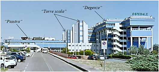
Figure 1. Side-view of the hospital complex.
Since it contains the surgical division of the hospital and hence a large number of earthquake-sensitive NSCs, the “Piastra” building is considered hereafter.
A survey of the non-structural components (NSCs) and technological content (TC) of the building was conducted in previous studies (Lupoi et al., 2008; Gandelli et al., 2018). NSCs and TC were categorized as either “drift-sensitive” or “acceleration-sensitive” elements (Table 1) and failure thresholds were established as the median capacity (Cm) of relevant fragility curves available in literature (Johnson et al., 1999; Lupoi et al., 2008; Cosenza et al., 2014).
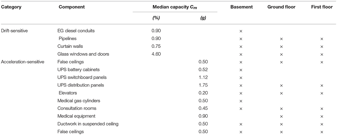
Table 1. Floor distribution of non-structural components (NSCs) and pieces of technological content (TC).
Reference Seismic Scenario and Performance Requirements
In order to assess the seismic response on the “Piastra” building, non-linear history analyses were carried out considering two design earthquakes and the relevant performance requirements provided by the Italian Building code (CSLLPP - Consiglio Superiore dei Lavori Pubblici, 2018): the BDE was assumed for the design of SHDs for the retrofit of the building and hence for the assessment of the structural integrity of the reinforced-concrete frame, whereas the FDE was taken into account to verify the fulfillment of the fully-operational performance (OP) requirement for non-structural elements. Design spectra were defined considering the code's provisions (CSLLPP - Consiglio Superiore dei Lavori Pubblici, 2018) for a strategic structure (functional class IV, cu = 2.0) located in Lamezia Terme (16.18° longitude, 38.58° latitude), topographic category T1, and a nominal life of the building VN = 100 years (corresponding to a reference period VR = cu • VN = 200 years). Based on available information (Lupoi et al., 2008), the soil at and below the foundation level is mainly composed of sand and gravel with good mechanical properties (friction angle φ = 30÷35°). The risk of liquefaction is negligible and a type B soil was assumed. These assumptions led to peak ground acceleration (PGA) values of 0.17 g at FDE, and 0.45 g at BDE. Seven independent ground motion were selected for either seismic design level (Table 2) among records with magnitude 6.0 ≤ Mw ≤ 8.0 and epicentral distance 0 ≤ Rep ≤ 35 km using the target spectrum-matching criterion for fundamental periods T ≤ 2.0 s. In particular, compliant natural records were searched within the European Strong-motion Database (Ambraseys et al., 2002) by means of REXEL v3.4 beta software (Iervolino et al., 2010). Since three-dimensional compatible ground motion records could not be found in the database, only the two horizontal acceleration components were considered, whereas the vertical acceleration component was neglected.
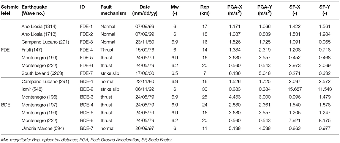
Table 2. Ground motion records for seismic analyses at FDE and BDE.
Seismic Retrofit Intervention
“As-Built” Structural Frame
The “Piastra” is a quite regular three-story building with dimensions of 140 m in the longitudinal direction (X-direction) and 50 m in the transversal direction (Y-direction). The story heights are 5.1 m (basement), 3.5 m (ground floor), and 4.5 m (first floor) respectively, for a total height of 13.1 m. Foundations are located at −5.1 m with respect to the ground level. The structural frame consists of cast-in-place reinforced concrete beams and columns and is divided into three blocks (block A, B, and C) by separation joints at each floor. The layout of the structural grid (Figure 2A) is common to each block, with bays of 7.2 m and 9.6 m in the longitudinal (X) and transversal (Y) directions, respectively. At basement level, the building is supported by 111 primary C-P1 type columns, 71 auxiliary C-P4 type columns, and 16 auxiliary C-P5 type columns. Auxiliary columns are used at the lowest level only, while primary columns are present at each floor (111 columns per floor), with cross-section as shown in Figure 2B; details of secondary columns can be found in another paper (Gandelli et al., 2018). The longitudinal beams have a conventional rectangular cross-section, while the transversal beams have a channel cross-section (Figure 2C).
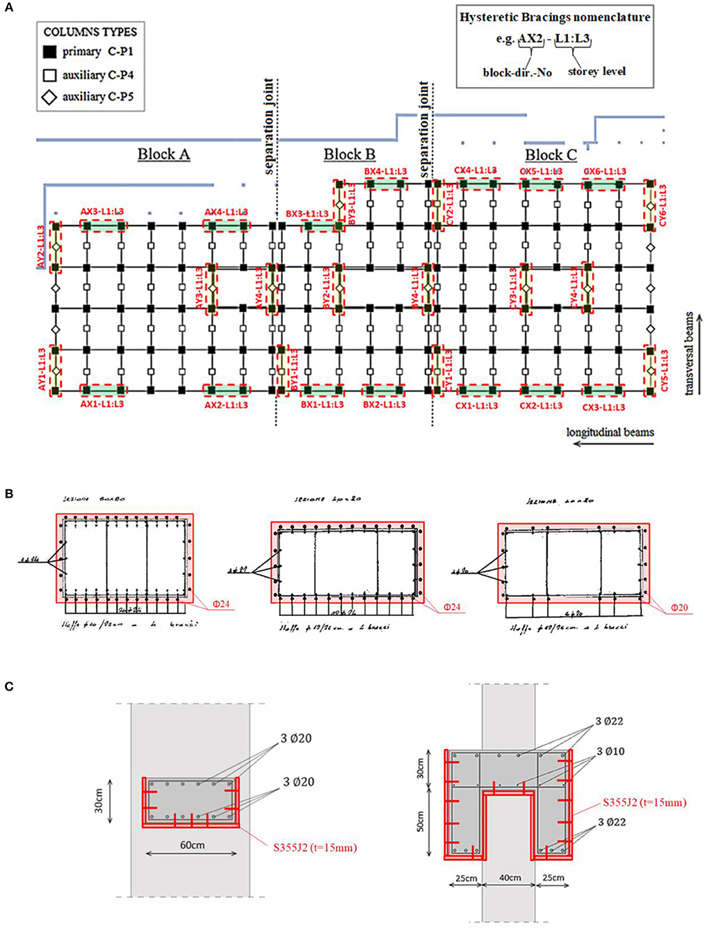
Figure 2. Structural layout of the “Piastra” building. (A) Columns grid (in black) and plan arrangement of Dissipative Braces (in red-dashed). (B) Cross-section of primary columns: (left) C-P1; (center) C-P2; (right) C-P3. (C) Cross-section of beams in the longitudinal (left) and transversal (right) directions. Proposed strengthening is drafted in red lines, superimposed to the original layout in black/gray.
Previous studies (Lupoi et al., 2008; Gandelli et al., 2018) showed that the “as-built” building frame could suffer severe structural damage, close to collapse, under moderate earthquakes corresponding to FDE level (PGA = 0.17 g), and that the “Piastra” needs to be retrofitted to achieve the safety performance level prescribed by the Code. A proposed retrofitting solution by means of DBs is described in the following section.
DB Layout
For the optimal design of the dissipative bracing (DB) layout several limitations/targets have to be taken into account, namely: (i) do not impair the distribution of medical functions within the medical center by, e.g., obstructing the passage to patients and doctors; (ii) limit at each floor the eccentricity between the center of mass and the center of lateral stiffness of the braced frame; (iii) restrain torsional motions during the seismic shaking.
In order to limit the length of the elements subjected to tension/compression and prevent their buckling, two DB units are installed in the same bay according to the “inverted V” configuration shown in Figure 3A. A conventional arrangement is supposed, with each DB consisting of a steel hysteretic damper (SHD) connected to the main frame by means of two rigid links (RLs).
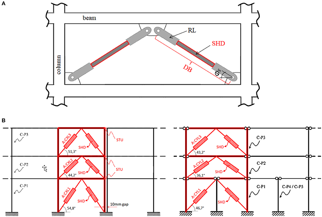
Figure 3. Layout in elevation of the dissipative bracing (DB) system. (A) Main components of a DB: steel hysteretic damper (SHD) and rigid links (RL). (B) Arrangement of DBs and shock-transmit units (STU) in the longitudinal (left) and transversal (right) structural frames.
At each floor and in either horizontal direction, the proposed DB layout envisages eight SHDs for both blocks A and B, and twelve SHDs for block C (Figure 2A). The units are installed on the perimeter of each block to restrain torsional motion. The nomenclature adopted to identify each DB is based on its horizontal and vertical localization; e.g. “AX2-L1” stands for block A, horizontal direction X, position 2, floor 1. Figures 2A, 3B show the proposed floor and elevation layouts for the DB system, respectively. Both DBs installed in the same bay share the same tag. Owing to the small gap (10 mm) provided by the separation joints in the longitudinal (X) direction, shock transmit units (STUs) are inserted at each floor to rigidly connect adjacent blocks and avoid possible hammering during the seismic shaking (Figure 3B).
Since the introduction of dissipative braces (DB) induces a considerable increase of axial load in structural members, local strengthening of beams and columns adjacent to DBs is often necessary (Ponzo et al., 2010; Di Cesare et al., 2014). The primary columns of the retrofitted bays are reinforced with additional layers of steel rebar along the lateral surface (Figure 2B) while thick steel plates are connected to the beams by means of stud anchors (Figure 2C). Beams and columns not directly connected to the dissipative bracing system maintain their original structural characteristics. It is worth noting that alternative solutions to mitigate the overstressing of beam and column elements have been proposed in literature (Apostolakis and Dargush, 2009; De Domenico et al., 2019b).
Design Procedure for DBs
Design parameters of the DBs have been selected by means of a step by step procedure based on a non-linear static analysis (NLSA) of the “as-built” structure (Di Cesare and Ponzo, 2017). As first step, the equivalent SDOF system of the bare frame (F) of each block of the “Piastra” building is determined from the relevant capacity curve (F-d) calculated in a previous study (Gandelli et al., 2018). Assuming that the dynamic response of the bare frame is governed by the 1st eigen-mode, the idealized elastoplastic response (F*-d*) of the equivalent SDOF is defined as and (being the “first mode participation factor,” mi and ϕi the mass and the normalized modal component of the ith story, respectively). As an example, Figure 4 shows the capacity curves, both physical and reduced (equivalent SDOF), for block A along the two horizontal directions.
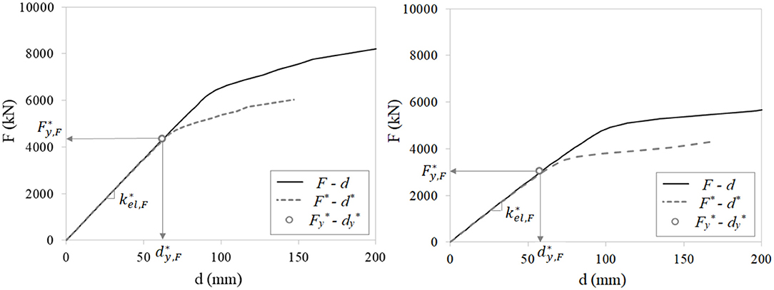
Figure 4. Physical l (F-d) and reduced (F*-d*) capacity curves calculated for the bare frame of block A along longitudinal (X, left) and transversal (Y, right) directions.
Eventually, the reduced mass (m*) and the elastic stiffness () of the equivalent SDOF system are calculated as and . Table 3 provides the reduced properties of the bare frame of the three blocks along both horizontal directions. The blocks exhibit a quite uniform behavior with close values of yielding displacement () along both horizontal directions.
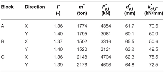
Table 3. Equivalent SDOF parameters of the bare frames of the three blocks in both horizontal directions.
In the second step of the procedure the design parameters of the dissipative bracing (DB) system are determined. The force-displacement behavior of the DB system is idealized by means of an elastic perfectly-plastic SDOF system defined by the yielding force (), the elastic stiffness (), the yielding displacement (), and the ductility factor (). In order to achieve consistent responses of the three blocks at BDE, the same target displacement for the equivalent SDOF retrofitted system (F+DB) has been assumed along both horizontal directions (). This assumption additionally allows to limit the maximum force transmitted by STU units as a result of differential movements. According to well-regarded design recommendations (Vayas, 2017), the DB system is conceived in order to keep the structural members of the frame in the elastic range while the seismic energy is dissipated by the dissipative bracings only; hence the target displacement is set to , below the yielding displacement () of each block (ranging from 60.1 to 65.5 mm, see Table 3). The displacement of the equivalent SDOF retrofitted system (F+DB) is hence estimated from the displacement response spectrum () by means of an iterative procedure. The effective period () of the equivalent SDOF system (F+DB) is calculated as:
being and the elastic stiffness of the frame (F) and the effective stiffness of the dissipative bracing (DB), respectively. The equivalent viscous damping of the dissipative bracing () is calculated as Dwairi et al. (2007):
The ductility factor () of the dissipative bracing has been set to which is a typical value for steel hysteretic dampers (Di Cesare and Ponzo, 2017), resulting in the yielding displacement . For the three examined blocks, convergence of the iterative procedure () has been reached in few iterations leading to the design parameters of the equivalent SDOF dissipative bracing (DB) summarized in Table 4.
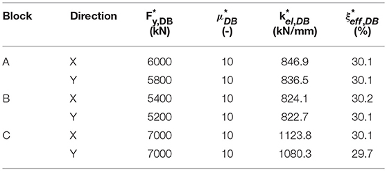
Table 4. Equivalent SDOF design parameters of the DB system for the three blocks of “Piastra” buiding.
In the third step of the procedure, the overall damping force () and stiffness () of the equivalent SDOF dissipating system are distributed along the height of the frames (Figure 5) proportionally to the yielding force (Fy,F,i) and the elastic stiffness (kel,F,i) of each story. In particular, the elastic stiffness (kel,DB,i) and the yielding force (Fy,DB,i) at the i-th level (Table 5) are calculated as Di Cesare and Ponzo (2017):
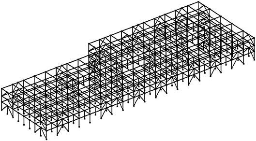
Figure 5. 3D FEM model of the retrofitted “Piastra” building used in nonlinear response history analyses.
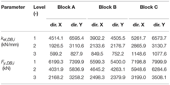
Table 5. Distribution in elevation of the elastic stiffness (kel,DB,i) and the yielding force (Fy,DB,i) of the DB system.
In the last step, the elastic stiffness (kel,DB,i,s) and the damping force (Fy,DB,i,s) of any individual dissipating brace (DB) are calculated based on the number (nDB,i) and inclination angle (ϕs, Figure 3) of the braces at the i-th story along the considered horizontal direction:
The resulting design parameters of the individual DB units are reported in Table 6.
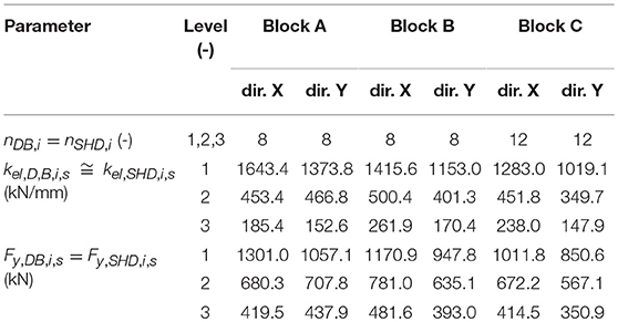
Table 6. Design parameters of the DB units.
The Rigid links (RLs), provided to connect the SHDs to the r.c. frame, are sized in order to act as stiff connections that operate in their elastic field (Fy,RL,i,s ≫ Fy,DB,i,s) and allow the overall force-displacement response of the DB system being governed by SHDs only; that is kel,DB,i,s ≅ kel,SHD,i,s (Di Cesare and Ponzo, 2017).
Numerical Analyses
A 3D model of the retrofitted “Piastra” building (Figure 5) was created in the OpenSees® FEM software (McKenna et al., 2000).
To model columns and beams, non-linear “BeamWithHinges” elements (OpenSeesWiki online manual)1, comprising two fiber sections at either end (where plastic hinges are likely to be triggered) and a linear-elastic region in the middle of the element, were used. The length of the plastic hinges (LP) was estimated in accordance with the formula LP = 0.08L + 0.022fydd, where L is the length of the beam/column member, and fyd and d are the yield strength and the diameter of longitudinal steel reinforcing bars, respectively (Paulay and Priestly, 1992). The Kent-Scott-Park formulation, as modified by Karsan-Jirsa (“Concrete01-ZeroTensileStrength”), and a bilinear material law with kinematic hardening (“Steel01”) were used to model concrete and steel, respectively; the relevant mechanical properties were assumed from a previous survey (Lupoi et al., 2008) as: steel elastic modulus E = 210,000 MPa; steel yield stress fyd = 430 MPa; concrete elastic modulus E = 30,000 MPa; concrete compressive strength fcd = 41 MPa. Softening of concrete-fibers was disregarded, while strain-parameters were set as recommended by the Italian Building Code (CSLLPP - Consiglio Superiore dei Lavori Pubblici, 2018); conservatively, hardening of steel-fibers was neglected too. A more detailed description of the modeling assumptions for r.c. elements can be found in the referred study (Gandelli et al., 2018).
The gravitational dead loads (Gk) were evaluated according to the original design report, while live loads (Qk) were set according to the provisions of the Italian Building Code (CSLLPP - Consiglio Superiore dei Lavori Pubblici, 2018). The resulting load distributions (from bottom to upper floor) are: (1) 5.28; 5.28; 4.38 kN/m2 for dead loads, and (2) 3.00; 3.00; 0.50 kN/m2 for live loads, respectively.
The following boundary conditions were assigned to the model:
1. The nodes at foundation level were linked together and subjected to the application of “UniformExcitation” seismic inputs (OpenSeesWiki online manual)1;
2. Vertical loads were assigned to every node according to the floor distribution of permanent (Gk) and live (Qk) loads defined above, while relevant translational masses were evaluated as ;
3. A “RigidFloorDiaphragm” multi-points constraint was introduced at each floor to prevent relative displacements between nodes belonging to the same floor slab (OpenSeesWiki online manual)1.
“Two node link” elements with a perfectly-rigid behavior along axial direction only were used to model STU devices that connect adjacent blocks, while for simplicity the DBs were modeled by means of bilinear hysteretic (material type “Steel01”) trusses with a uniform behavior (axial stress-strain) over the entire length of the elements (OpenSeesWiki online manual)1. In order to reproduce the actual bilinear force-displacement response of the each physical DB, fictitious values of the cross-sectional area (ADB, i, s) and the elastic modulus (EDB, i, s) assigned at each truss element were calculated as:
being σy, DB = 355MPa the assumed yielding stress and LDB, i, s the length of the i-th DB element. The stiffness hardening ratio r (i.e., the ratio of the post-yield modulus to the elastic modulus) was taken as 2.5%, which falls in the middle of the range of typical values of r (from 0.05 to 5.0%) reported for SHDs (Vayas, 2017). The resulting parameters of the hysteretic truss elements are reported in Table 7.
Table 7. Parameters of hysteretic truss elements for FEM analyses.
Seismic Response Assessment
According to the Italian Building Code (CSLLPP - Consiglio Superiore dei Lavori Pubblici, 2018), the seismic performance of the “Piastra” building is evaluated at both FDE and BDE considering the average response over the seven independent history analyses calculated in OpenSees FE code. The structural integrity requirement is checked at BDE while the full-operation of NSCs is verified at FDE.
In agreement with the design assumption for the DB system, the structural response of any of the three blocks is uniform along either horizontal direction at both FDE and BDE. While this outcome is quite obvious in the longitudinal (X) direction because of the STUs that act as rigid links between the adjacent frames, in the transversal (Y) direction it proves the fair tuning of effective stiffness and damping of SHDs. Figure 6 shows the average displacement envelopes for the two considered seismic design levels. In particular, at FDE (Figure 6, left), the average peak displacement at roof level is 13 mm, while at BDE (Figure 6, right) it ranges from 46 mm to 53 mm in the longitudinal and transversal direction respectively, below the yielding threshold of the frame. Thereby the retrofitting solution permits to keep the r.c. members of the “Piastra” building in the elastic range. Figure 6 reports also the average displacement envelope of the Bare Frame at FDE: at this intensity level the “as built” configuration of the building exhibits displacements of 81 and 95 mm in the longitudinal and transversal direction, respectively. The frame is expected to suffer structural damage at the columns of the upper story (C-P3) where plastic hinges are triggered and, as highlighted in a previous study (Gandelli, 2017), about 70% of columns' cross-sections are close to their ultimate capacity.
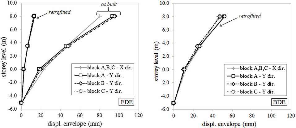
Figure 6. Average displacement envelopes of the three blocks for FDE (left) and BDE (right).
The response of the DB system calculated by OpenSees program is in good accordance with the results of the preliminary design. Figure 7 shows the force-displacement loops of the SHD elements placed in the longitudinal direction of block B in position No. 1 at the three story levels (L1:L3). It can be noted that during the weak FDE-1 ground motion (Figure 7, left) the response of the unit at the 1st level (basement) practically remains within the elastic range, whereas the unit at the 3rd level experiences small plastic deformation (up to 5.0 mm). On the contrary, under the strong BDE-1 ground motion (Figure 7, right), at each story the SHD units develop large plastic deformations (up to 20 mm for the unit at the 3rd level), entailing a considerable dissipation of seismic energy.
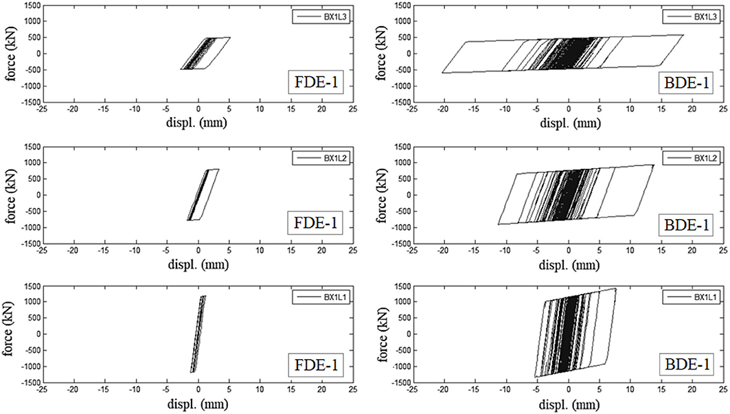
Figure 7. Force-displacement response of DBs installed in position No. 1 at each story level (L1:L3) of the longitudinal frame (dir. X) of block B during FDE-1 (left) and BDE-1 (right) ground motions.
The proposed DB system proves to be a viable solution not only for the structural safety of the frame, but also for the seismic protection of “drift-sensitive” NSCs and TC. Since the failure threshold of the weakest element (0.75% for curtain walls) is not exceeded even during the most severe BDE earthquakes, the fully-operation condition is always attained from these elements. As shown in Figures 8A,B, the drift envelopes are indeed similar along both horizontal directions with average peak values of 0.16 and 0.53% under Frequent (FDE) and Basic Design Earthquakes (BDE), respectively. In particular for the Frequent Design Earthquake this allows a reduction of peak drifts of 79–89% along the longitudinal direction and 85–87% along the transversal one in comparison to the Bare Frame (Figure 8A).
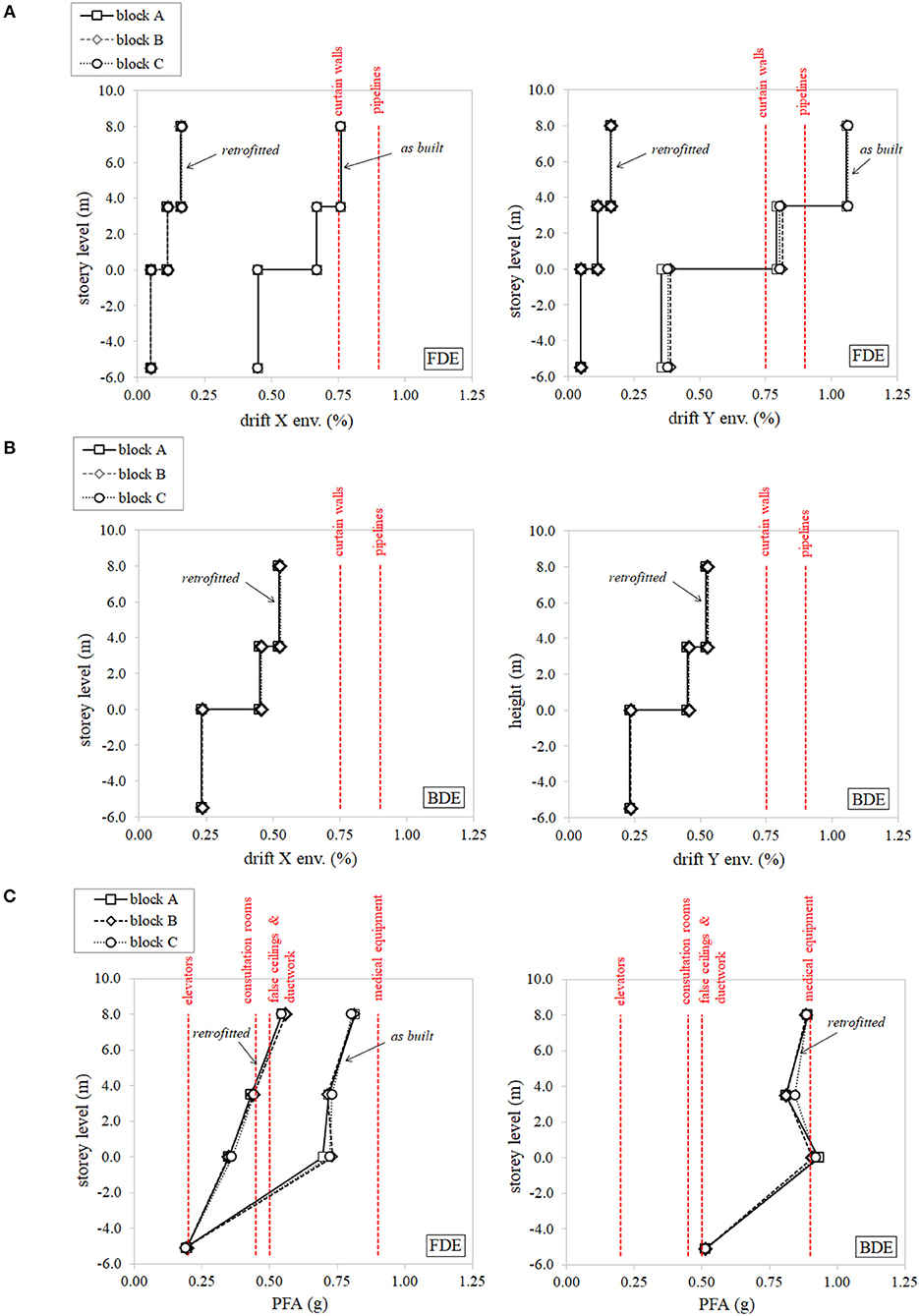
Figure 8. Seismic performance of non-structural components and content (red-dashed lines represent the failure thresholds of the weakest elements). Average inter-story drift envelopes in the longitudinal (X-left) and transversal (Y-right) direction for both (A) FDE and (B) BDE levels. (C) Average peak floor acceleration (PFA) distributions calculated for FDE (left) and BDE (right).
However, the seismic performance of “acceleration-sensitive” elements is quite alarming, as illustrated in Figure 8C, where the peak floor acceleration (PFA) envelopes are compared to the failure threshold of some NSCs and TC. At FDE (Figure 8C, left), the following potential dysfunctions can be envisaged for the retrofitted building:
• Out of order of the elevators at every floor (resulting in slow-down in the transportation of injured patients);
• Temporary unavailability of consultation rooms at both ground and first floor levels due to possible overturning of not-restrained furniture and equipment;
• Detachment and falling of false ceilings and ductwork.
As a consequence, despite the low intensity of the seismic event, the hospital complex would not be capable to effectively manage the emergency response after the Frequent Design Earthquake, which is instead required by the Italian Building Code (CSLLPP - Consiglio Superiore dei Lavori Pubblici, 2018). This is most likely due to the stiffening effect of the DB system that, according to the design practice, is designed to constrain the displacement and protect the building during strong BDE earthquakes, but also shortens the period of vibration and increases the acceleration; since the damping introduced during FDE ground motions is small (Figure 7-left), the DB system appears not effective to protect “acceleration-sensitive” content. Nevertheless, it must be noted the envisaged scenario following retrofit with DBs is anyway better compared to the one expected for the “as built” structure for which higher PFA are predicted due to the negligible structural damping (ξ = 5%) before the onset of plastic hinges in the columns.
Although not required by the Italian Building Code (CSLLPP - Consiglio Superiore dei Lavori Pubblici, 2018), the dynamic response of “acceleration-sensitive” NSCs and content is assessed at BDE seismic level in order to depict the potential scenario after a catastrophic earthquake (Figure 8C, right). In addition to the previously detected failures, also medical equipment at ground floor (e.g., computed tomography scan, magnetic resonance imaging, cardio vascular imaging, and ultrasound scan) are likely to be damaged causing a huge economic loss.
In order to limit damages to “accelerations-sensitive” non-structural components (NSCs) and content, other retrofitting techniques, like base-isolation, appear to be more suitable. The effectiveness of base isolation was indeed proven in a number of shake-table tests, as well as in real applications, e.g., from the actual response of base-isolated hospitals under real earthquakes (Nagarajaiah and Xiaohong, 2000). A design procedure for curved surface sliding isolators (CSSs) aiming at the protection of NSCs has been recently published (Gandelli et al., 2019) which allows, through a significant reduction of floor accelerations, to ensure the full operation of hospital services and the integrity of medical equipment. However, in certain cases, base isolation can be not viable due to the large seismic displacements at base level that can cause the pounding with adjacent buildings. This could be e.g., the case of the investigated case study, where the “Piastra” building, hosting the most critical surgical division of the hospital, could be base isolated, but with the risk of striking with the “Degenze” and “Torre Scala” structures. This issue can be overcome e.g., by combining the isolation system with a tuned mass damper placed over the base slab; this solution, in addition to mitigate peak floor accelerations, was proposed to limit the displacement of the isolators (De Domenico and Ricciardi, 2018).
Conclusions
The effectiveness of the intervention of seismic retrofit of hospital buildings by means of hysteretic bracing systems has been investigated in this study. The “Giovanni Paolo II” hospital of Lamezia Terme, located in a high seismic prone area in Southern Italy, is chosen as case-study. Since a previous survey demonstrated that the “Piastra” building of the medical complex could suffer heavy structural damages under moderate earthquakes, a retrofit intervention by mean of a dissipative bracing (DB) system has been designed according to the Italian Building Code (CSLLPP - Consiglio Superiore dei Lavori Pubblici, 2018). The preliminary design of the DB system is based on a non-linear static analysis whereas the seismic response of the hospital has been assessed by means of non-linear history analyses carried out in OpenSees FE code.
The proposed solution proves to be effective to protect the hospital complex from structural damage under severe BDE earthquakes (PGA = 0.45 g). The stiffening effect of the DB system has beneficial effects also for the protection of “drift-sensitive” NSCs and content. Indeed, the inter-story drift along either horizontal direction do not exceed the capacity of any NSC at FDE (PGA = 0.17 g) and, although not required by the assumed building code, even at the most demanding BDE.
On the contrary, concern arises about the suitability of hysteretic dampers for the protection of “acceleration-sensitive” elements of the medical complex. An alarming scenario can be indeed depicted after weak FDE events allowing to conclude that the hospital won't be able to manage the post-earthquake emergency. The following damages are predicted: (i) malfunction of the elevators that may slow-down the transportation of injured patients; (ii) detachment and collapse of false ceilings and supported ductwork; (iii) overturning of not-restrained furniture and equipment in medical consultation rooms leading to their temporarily unavailability.
This study, although not aiming to be exhaustive, emphasizes the potential inadequacy of conventional hysteretic bracing systems for the seismic retrofit of high-technological buildings, like hospitals, that contain a wide range of “acceleration-sensitive” elements. To overcome this issue, alternative solutions, like base-isolation and mass damping should be exploited which, thanks to mitigation of PFA, allow to ensure the full operation of hospital services after the quake.
Data Availability
The datasets generated for this study are available on request to the corresponding author.
Author Contributions
EG and JD carried out the FEM analyses. AT and VQ supervised the calculations as technical advisors of the project. EG wrote the paper.
Conflict of Interest Statement
EG and JD are employed by the company Maurer Engineering GmbH.
The remaining authors declare that the research was conducted in the absence of any commercial or financial relationships that could be construed as a potential conflict of interest.
Acknowledgments
The authors wish to thank Architect Carlo Nistico' for the support provided during the technical survey of the Giovanni Paolo II hospital of Lamezia Terme, and the Provincial Health Authority (ASP) of Catanzaro for the authorization to publish the results of the research.
Footnote
1. ^OpenSeesWiki, online manual. Available online at: http://opensees.berkeley.edu/wiki/index.php/Main_Page
References
Achour, N., Miyajima, M., Kitaura, M., and Price, A. (2011). Earthquake induced structural and non-structural damage in hospitals. Earthquake Spectra 27, 617–634 doi: 10.1193/1.3604815
Alexander, D. E. (2010). The L'Aquila earthquake of 6 April 2009 and italian government policy on disaster response. J. Nat. Resources Policy Res. 2, 325–342. doi: 10.1080/19390459.2010.511450
Ambraseys, N., Smit, P., Sigbjornsson, R., Suhadolc, P., and Margaris, B. (2002). Internet-Site for European Strong-Motion Data, European Commission, Research-Directorate General. Environment and Climate Programme. Available online at: http://isesd.hi.is/ESD_Local/frameset.htm
Antonucci, R., Balducci, F., Castellano, M. G., and Don,à, F. (2006). “Pre-casted RC buildings with buckling restrained braces: the example of the new building of the faculty of engineering in Ancona,” in Proceedings of the 2nd International FIB Congress (Napoli).
Antonucci, R., Cappanera, F., Balducci, F., and Castellano, M. G. (2007). “Adeguamento sismico del Liceo classico “Perticari” di Senigallia (AN),” in Proceedings of the XII ANIDIS conference (Pisa).
Apostolakis, G., and Dargush, G. F. (2009). Optimal seismic design of moment-resisting steel frames with hysteretic passive devices. Earthquake Eng. Struc. Dyn. 39, 355–76. doi: 10.1002/eqe.944
Braga, F., Buttarazzi, F., Dell'Asta, A., and Salvatore, W. (2015). Protezione Sismica di Edifici in c.a. con Controventi Dissipativi in Acciaio. Milano: Dario Flaccovio Editore.
Celano, F., Cimmino, M., Coppola, O., Magliulo, G., and Salzano, P. (2016). Report dei Danni Registrati a Seguito Del Terremoto del Centro Italia del 24 Agosto 2016 (Release 1). Network ReLUIS (Rete dei Laboratori Universitari di Ingegneria Sismica). Available online at: http://www.reluis.it/images/stories/Centre%20Italy%20earthquake%20damage%20report%20-%20R1.pdf
Cosenza, E., Di Sarno, L., Maddaloni, G., Magliulo, G., Petrone, C., and Prota, A. (2014). Shake table tests for the seismic fragility evaluation of hospital rooms. Earthquake Eng. Struc. Dyn. 44, 23–40. doi: 10.1002/eqe.2456
CSLLPP - Consiglio Superiore dei Lavori Pubblici (2018). Norme Tecniche per le Costruzioni. No. 42 of 20 February 2018. (Rome: Gazzetta Ufficiale della Repubblica Italiana).
De Domenico, D., Impollonia, N., and Ricciardi, G. (2019a). Seismic retrofitting of confined masonry-RC buildings: The case study of the university hall of residence in Messina, Italy. Ingegneria Sismica 36, 54–85.
De Domenico, D., and Ricciardi, G. (2018). Earthquake-resilient design of base isolated buildings with TMD at basement: application to a case study. Soil Dyn. Earthquake Eng. 113, 503–521. doi: 10.1016/j.soildyn.2018.06.022
De Domenico, D., Ricciardi, G., and Takewaki, I. (2019b). Design strategies of viscous dampers for seismic protection of building structures: a review. Soil Dyn Earthquake Eng. 118, 144–165. doi: 10.1016/j.soildyn.2018.12.024
Di Cesare, A., and Ponzo, F. C. (2017). Seismic retrofit of reinforced concrete frame buildings with hysteretic bracing systems: design procedure and behaviour factor. Shock Vibration. 2107. doi: 10.1155/2017/2639361
Di Cesare, A., Ponzo, F. C., and Nigro, D. (2014). Assessment of the performance of hysteretic energy dissipation bracing systems. Bull. Earthquake Eng. 12, 2777–2796. doi: 10.1007/s10518-014-9623-z
Dicleli, M., and Milani, A. S. (2016). Multi-Directional Torsional Hysteretic Damper (mthd). US Patent No: US20120066986A.
Dwairi, H. M., Kowalsky, M. J., and Nau, J. M. (2007). Equivalent damping in support of direct displacement-based design. J. Earthquake Eng. 11, 512–530. doi: 10.1080/13632460601033884
FEMA - Federal Emergency Management Agency (1999). Earthquake Loss Estimation Methodology Hazus99. SR2: Techical Manual, Washington, DC.
Gandelli, E. (2017). Advanced Tools for the Design of Sliding Isolation Systems for Seismic-Retrofitting of Hospitals. [Doctoral dissertation]. Politecnico di Milan, Italy.
Gandelli, E., Dubini, P., and Quaglini, V. (2019). “A design procedure for seismic isolation retrofit of hospitals tailored to the protection of non-structural components,” in Proceedings of the 4th International Workshop on the Seismic Performance of Non-Structural Elements (SPONSE) (Pavia), 22–23.
Gandelli, E., Quaglini, V., Dubini, P., Limongelli, M. P., and Capolongo, S. (2018). Seismic isolation retrofit of hospital buildings with focus on non-structural components. Ingegneria Sismica Int. J. Earthquake Eng. XXXV, 20–55.
Hitaka, T., and Matsui, C. (2003). Experimental studies of on steel shear wall with slits. J. Struc. Eng. 129, 586–595. doi: 10.1061/(ASCE)0733-9445(2003)129:5(586)
Iervolino, I., Galasso, C., and Cosenza, E. (2010). REXEL: computer aided record selection for code-based seismic structural analysis. Bull. Earthquake Eng. 8, 339–362. doi: 10.1007/s10518-009-9146-1
Johnson, G. S., Sheppard, R. E., Quilici, M. D., Eder, S. J., and Scawthorn, C. R. (1999). Seismic Reliability Assessment of Critical Facilities: A Handbook, Supporting Documentation, and Model Code Provisions. New York, NY: University at Buffalo. Available online at: https://ubir.buffalo.edu/xmlui/handle/10477/875
Lupoi, G., Franchin, P., Lupoi, A., Pinto, P. E., and Calvi, G. M. (2008). Probabilistic Seismic Assessment for Hospitals and Complex-Social Systems. ROSE Research Report No. 2008/02. IUSS Press.
Masi, A., Santarsiero, G., Gallipoli, M. R., Mucciarelli, M., Manfredi, V., Dusi, A., et al. (2014). Performance of the health facilities during the 2012 Emilia (Italy) earthquake and analysis of the Mirandola hospital case study. Bull. Earthquake Eng. 12, 2419–2443. doi: 10.1007/s10518-013-9518-4
Mazza, F., and Vulcano, A. (2015). Displacement-based design procedure of damped braces for the seismic retrofitting of r.c. framed buildings. Bull Earthquake Eng. 13, 2121–2143. doi: 10.1007/s10518-014-9709-7
McKenna, F., Fenves, G. L., and Scott, M. H. (2000). Open System for Earthquake Engineering Simulation. PEER Report, Berkeley, CA.
Medeot, R., and Chiarorro, R. (1996). Multidirectional mechanic hysteresis anti-seismic device for isolating the bases of constructional systems having high mutual displacements. US patent No. US5806250A
Nagarajaiah, S., and Xiaohong, S. (2000). Response of base-isolated USC hospital building in Northridge earthquake. J. Struc. Eng. 126, 1177–1186. doi: 10.1061/(ASCE)0733-9445(2000)126:10(1177)
Paulay, T., and Priestly, M. J. N. (1992). Seismic Design of Reinforced Concrete and Masonry Buildings. New York, NY: Wiley.
Petrone, C., Di Sarno, L., Magliulo, G., and Cosenza, E. (2016). Numerical modelling and fragility assessment of typical freestanding building conte-nts. Bull. Earthquake Eng. 15, 1609–1633. doi: 10.1007/s10518-016-0034-1
Ponzo, F. C., Di Cesare, A., Arleo, G., and Totaro, P. (2010). Protezione sismica di edifici esistenti con controventi dissipativi di tipo isteretico: aspetti progettuali ed esecutivi. Progettazione Sismica 4, 50–75.
Priestley, M. J. N. (2000). “Performance based seismic design,” in Proceedings of the 12th World Conference on Earthquake Engineering (WCEE) (Auckland).
Rossetto, T., Peiris, N., Alarcon, J. E., So, E., Sargeant, S., Free, M., et al. (2011). Field observations from the Aquila, Italy earthquake of April 6, 2009. Bull. Earthquake Eng. 9, 11–37. doi: 10.1007/s10518-010-9221-7
Skinner, R. I., Kelly, J. M., and Heine, A. J. (1974). Hysteretic dampers for earthquake-resistant structures. Earthquake Eng. Struc. Dyn. 3, 287–296. doi: 10.1002/eqe.4290030307
Skinner, R. I., Tyler, R. G., Heine, A. J., and Robinson, W. H. (1980). Hysteretic dampers for protection of structures from earthquakes. Bull. N. Zealand Soc. Earthquake Eng. 13, 22–36.
Takeuchi, T, Nakamura, H., Kimura, I., Hasegawa, H., Saeki, E., and Watanabe, A. (1999). Buckling Restrained Braces and Damping Steel Structures. US patent No. US20050055968A1.
Tsai, K. C., Chen, H. W., Hong, C. P., and Su, Y. F. (1993). Design of steel triangular plate energy absorbers for seismic resistant construction. Earthquake Spectra 9, 505–528. doi: 10.1193/1.1585727
USGS - United States Geological Survey (1996). USGS Response to an Urban Earthquake - Northridge '94. Available online at: http://pubs.usgs.gov/of/1996/ofr-96-0263/introduc.htm#impacts
Vayas, I. (2017). INNOSEIS Project - Valorization of INNOvative anti-SEISmic Devices. Deliverables Available online at: http://innoseis.ntua.gr/deliverables.php?deliverable=reports
Keywords: seismic retrofit, hysteretic braces, hospitals, non-structural components, acceleration-sensitive elements
Citation: Gandelli E, Taras A, Distl J and Quaglini V (2019) Seismic Retrofit of Hospitals by Means of Hysteretic Braces: Influence on Acceleration-Sensitive Non-structural Components. Front. Built Environ. 5:100. doi: 10.3389/fbuil.2019.00100
Received: 20 May 2019; Accepted: 31 July 2019;
Published: 20 August 2019.
Edited by:
Dario De Domenico, University of Messina, ItalyReviewed by:
Antonio Di Cesare, University of Basilicata, ItalyGiuseppe Ricciardi, University of Messina, Italy
Copyright © 2019 Gandelli, Taras, Distl and Quaglini. This is an open-access article distributed under the terms of the Creative Commons Attribution License (CC BY). The use, distribution or reproduction in other forums is permitted, provided the original author(s) and the copyright owner(s) are credited and that the original publication in this journal is cited, in accordance with accepted academic practice. No use, distribution or reproduction is permitted which does not comply with these terms.
*Correspondence: Emanuele Gandelli, ZS5nYW5kZWxsaUBtYXVyZXIuZXU=