 Felice Carlo Ponzo
 Antonio Di Cesare
 Nicla Lamarucciola
 Domenico Nigro
- University of Basilicata, School of Engineering, Potenza, Italy
This paper describes a seismic design procedure for low-damage buildings composed by post-tensioned timber framed structures coupled with hysteretic dissipative bracing systems. The main goal of the design procedure is preventing or limiting earthquake-induced damage to the structural and non-structural elements. For this aim, a target design displacement is defined according to the desired performance level. Then, the corresponding design force, strength, and stiffness of the post-tensioning and of the dissipative braces are evaluated in order to size post-tensioned connections and dissipating devices. The results of shaking table testing performed at the University of Basilicata are also reported. A prototype model −2/3 scaled, three-dimensional, and three stories with a post-tensioned timber structure without and with V-inverted braces and U-shaped flexural steel dampers—has been extensively tested. During testing, the specimen was subjected to a set of seven earthquakes at different intensity levels of the peak ground acceleration. The effectiveness of the bracing system and the reliability of the proposed procedure are experimentally demonstrated. Non-linear dynamic analyses have been performed in order to simulate the experimental seismic response. The numerical model is based on a lumped plasticity approach, which combines the use of elastic elements with linear and rotational springs representing energy dissipating devices and plastic rotations of the connections. The numerical results accurately predict the non-linear behavior of the prototype model, obtaining a satisfactory matching with the target drift considered for design.
Introduction
According to the current seismic code requirements, buildings are expected to provide suitable structural safety level but do not explicitly prevent structural and non-structural damages or maintain structural functionality even after strong earthquakes. The resultant seismic damages are often difficult and financially prohibitive to repair. The effects of major earthquakes have proved the inadequacy of conventional buildings in terms of suffered damages to structural and not structural elements. Further improvements in seismic design and new approaches based on low damage methodologies and cost-efficient technologies are needed (Polocoşer et al., 2018; Pu et al., 2018). The implementation of seismic protection systems, such as dissipative devices (Di Cesare and Ponzo, 2017; Mazza and Mazza, 2019) and/or rocking systems (Ponzo et al., 2012; Di Cesare et al., 2017; Wang and Zhu, 2018), reduces seismic demand and/or increases the lateral capacity of structures, minimizing residual drift, and structural damage. It has been proved that timber structures have the capacity to withstand strong earthquakes without collapsing due to the light weight of wood material, elastic deformation capacity, and ductility of connections (Ugalde et al., 2019). Conventional wooden buildings are usually regular and the seismic resisting structures are shear walls with ductile foundation anchorages designed against the base shear force. In these cases, the maximum seismic forces are limited by the activation of inelastic deformations that could cause serious damages at predefined locations in the structure. Among the recent research on the concept of low-damage structures, post-tensioned timber-framed buildings with dissipative bracing systems can be designed to absorb energy during strong earthquakes, confining the inelastic deformations in replaceable ductile fuses while the structure returns to the initial position after severe earthquake.
The post-tensioned system is a recent technology mainly adopted in seismic areas. This technique is based on the PRESSS system, originally developed for the precast concrete frames and walls (Priestley et al., 1999), and consists of post-tensioning force combined with mass timber beam, column, and wall elements. The post-tensioned steel bars join the structural timber elements avoiding cracking of the structural members by softening the structural response elastically through rocking mechanisms (Buchanan et al., 2008). The Pres-Lam system allows the design of timber frames with wide bay lengths (8–12 m) and reduced cross-sections of structural elements (Estévez-Cimadevila et al., 2016). The use of a dissipative bracing system within a framed structure can provide significant additional stiffness and damping, reducing inelastic deformations, and internal forces. Dissipative bracing systems enable the attainment of much higher standards of seismic performance, minimizing damage after the design earthquake level, improving resilience. The system allows the devices to respond elastically at the Service Level Earthquake (SLE) and exhibit non-linear behavior at Design Basis Earthquake (DBE) (Federal Emergency Management Agency, 2012). A single-story post-tensioned frame with dissipative braces is shown in Figure 1. The representative model of the braced post-tensioned frame (BF) consists of the typical “flag-shaped” behavior as a combination of two components in parallel: (i) the bilinear elastic model representative of the self-centering capability of the post-tensioned bare frame (F) and (ii) the hysteretic model representative of the dissipative bracing system (DB). The replaceable steel dampers (D) of the bracing system (B) work as structural fuses that effectively reduce the forces imposed on the rest of the structural elements through the steel yielding. The ratio between elastic behavior (free rocking) of the bare post-tensioned frame and the amount of dissipation provided by the damping bracing system, represented by the βF parameter, is the main aspect that affects the seismic response of the structure.
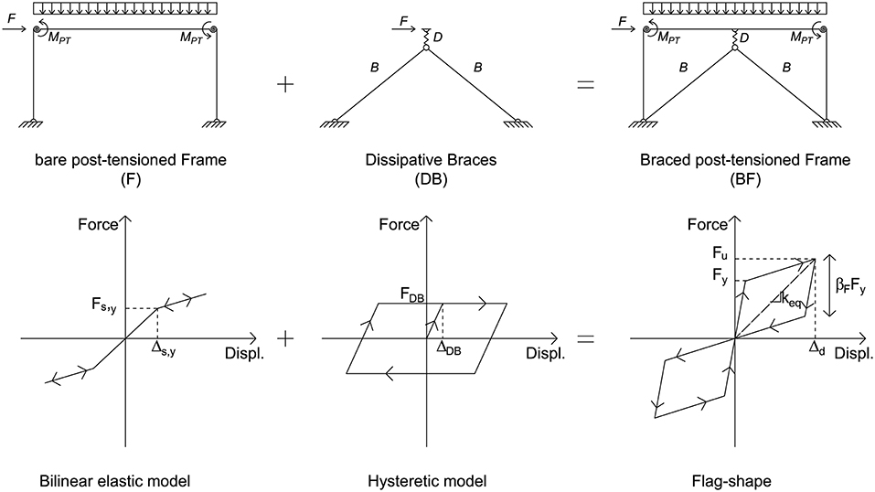
Figure 1. Fundamentals of post-tensioned frame structure with dissipative bracing system.
Regarding the seismic design of buildings with dissipative bracing systems including hysteretic dampers, several studies have been based on the Displacement Based Design (DBD) procedure (Lin et al., 2003; Zahrai and Froozanfar, 2018; Mazza and Mazza, 2019; Nuzzo et al., 2019). The base concept of DBD, originally developed by Priestley et al. (2007), consists in the approximation of a multi-degree of freedom (MDOF) structure in a single degree of freedom (SDOF) system with equivalent secant stiffness and viscous damping at the design displacement (Priestley, 2000; Priestley and Grant, 2005; Pei et al., 2012). Usually, design values are suggested within the design code depending on structural types or governed by allowable material strain limits. Recently, the application of the DBD method has been extended toward the design of timber buildings (Ugalde et al., 2019), such as CLT shear walls (Di Cesare et al., 2019a), coupled timber walls (Newcombe et al., 2011), and post-tensioned timber frames without and with the addition of dissipative rocking systems (Newcombe et al., 2010; Di Cesare et al., 2012, 2014; Pei et al., 2012). However, DBD applications to timber-framed buildings remain largely unexplored, and new techniques are still being investigated aiming to minimize residual damage induced by earthquakes.
An extensive program of shaking table tests has been developed in order to assess the effectiveness of different passive energy dissipating systems in controlling the seismic vibrations of post-tensioned timber framed buildings. The experimental campaign, carried out considering a 3D, 2/3 scaled timber frame, is part of a collaboration between the University of Basilicata (UNIBAS, Italy) and the University of Canterbury (UoC, New Zealand) (Di Cesare et al., 2012, 2017). The project aim is to evaluate the feasibility of applying jointed ductile post-tensioning technology to glue-laminated (glulam) timber (Smith et al., 2014), a more widespread engineered timber material, and to evaluate the increasing seismic performance due to the addition of various dissipative forms based on rocking mechanisms and on bracing systems.
In this paper, a DBD procedure for post-tensioned timber-framed buildings with hysteretic dissipative bracing systems is proposed. The main performance objective of the proposed method consists in preventing seismic damage to the frame elements and connections, fixing a target displacement Δd (or drift) and typical flag-shape parameters related to the reliable amount of dissipation of the braced post-tensioned frame under a reference level of seismic intensity. Starting from these parameters, the proposed method allows to evaluating the post-tensioning (PT) forces and the dissipative devices. The proposed procedure has been applied to design the hysteretic dampers of a three-story post-tensioned timber frame prototype model equipped with a V-inverted hysteretic dissipative bracing system, for which the preliminary results are reported in Di Cesare et al. (2019b). The effectiveness of the dissipative bracing system in control of seismic vibrations has been proved through the comparison between the experimental results of the braced frame and the results of the bare frame.
Moreover, the experimental results are endorsed by non-linear dynamic analysis, carried out in order to simulate experimental results firstly and then to validate the design results.
Seismic Design of Post-Tensioned Timber Buildings With Dissipative Bracing Systems
Figure 2 summarizes the proposed seismic design procedure for post-tensioned timber structures with dissipative bracing systems. In the step-by-step procedure, the equivalent SDOF systems of the bare post-tensioned frame (F) and of the dissipative bracing system (DB) have been considered as a bilinear and hysteretic system working in parallel, providing the equivalent flag-shape response (Figure 1) of the combined braced post-tensioned frame (BF). The substitute SDOF structure has the same base shear Fu of the inelastic MDOF structure associated with secant stiffness ke and equivalent viscous damping ξeq at the design displacement Δd or drift θd. The equivalent elastic properties of the SDOF system allowed the design of the MDOF structure through an elastic displacement response spectrum, reduced by ξeq. Based on the flag-shape parameters, the equivalent contributions of the bare structure and of the dissipative bracing systems can be evaluated and distributed at each story. Finally, the design assumption must be verified and the design completed.
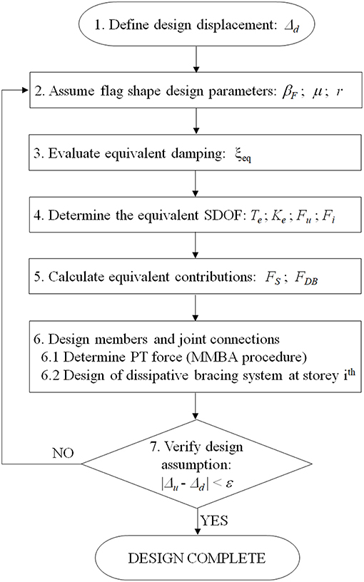
Figure 2. Design procedure.
Step 1. Define design displacement. The procedure starts defining a design displacement Δd at the design basis earthquake (DBE) corresponding to a target drift. The range of target drift for post-tensioned timber buildings varies between θd = 1.5 ÷ 2.5% based on non-structural elements and their connections and anchorages (Structural Timber Innovation Company Inc, 2013).
Step 2. Assume flag shape design parameters. The equivalent force-displacement of the braced post-tensioned frame consists in the flag-shaped hysteretic behavior (Figure 3C), which combines the equivalent bare post-tensioned frame (Figure 3A) with the equivalent dissipative bracing system (Figure 3B). The design parameters of the flag-shape of the equivalent SDOF system are the post-yield stiffness ratio r, the displacement ductility μ, and the re-centering ratio of the global system βF (flag loop parameter)—suggested values are βF = 0.6 ÷ 1.0; μ = 1.5 ÷ 3; r = 0.1 ÷ 0.3 (Pei et al., 2012).
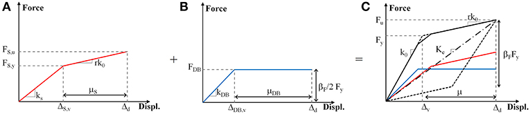
Figure 3. Equivalent SDOF systems of (A) Bilinear elastic model of the bare post-tensioned frame F; (B) Hysteretic model of dissipative bracing system DB; (C) Flag-shape of braced post-tensioned frame BF.
Step 3. Evaluate equivalent damping. The equivalent damping ξeq of the SDOF of the braced post-tensioned frame is evaluated as the sum of energy dissipated by viscous damping ξeq,v of the bare timber frame and inelastic hysteresis ξeq,h,v of the dissipative bracing system. In order to account for the random nature of earthquakes, a reduction factor k should be used to correct the hysteretic damping contribution (Priestley et al., 2007)—the suggested range is k = 0.6 ÷ 1—as a function of the specific hysteretic models, ductility levels, and periods (Ponzo et al., 2018; Di Cesare et al., 2019b). Using the general DBD methodology (Priestley et al., 2007), the equivalent damping is calculated as Equation (1).
A value of viscous damping ξeq,v = 2 ÷ 5% is considered acceptable for timber structures (Di Cesare et al., 2019a). The equivalent hysteretic damping related to the DB ξeq,h,v can be estimated by the following Equation (2) (Priestley and Grant, 2005).
Step 4. Determine the equivalent SDOF. The equivalent parameters of the SDOF system, in terms of design displacement Δd and equivalent mass me at the effective height He, are determined according to the fundamental mode, assuming a linear displacement profile of the ith-story Δi of the structure, as Equations (3), where mi and Hi are the story masses and story heights (Priestley et al., 2007).
From the target displacement Δd, the equivalent period Te and stiffness Ke of the SDOF system shall be calculated by direct transformation of the design acceleration response spectrum Sd (Te), as defined by Equations (4)1.
The ultimate force capacity Fu (maximum base shear) can be evaluated at the target design displacement (Priestley et al., 2007); then, based on the flag-shaped model reported in Figure 3C, the yielding force Fy of the equivalent SDOF system can be obtained by Equations (5).
Step 5. Calculate equivalent contributions. The equivalent contributions of post-tensioning and the dissipative bracing system can be evaluated on the base of the flag-shape model (Figure 3C). The hysteretic contribution of the dissipative bracing system (DB) is idealized as an elasto-plastic system (Figure 3B). Assuming the design ductility μDB of the equivalent SDOF of the dissipative system, the yield force FDB, the yield displacement ΔDB,y, and the elastic stiffness kDB are defined as Equations (6).
The ultimate FS,u and yielding FS,y forces as well as the yield displacement ΔS,y on the bare post-tensioned structure can be calculated as Equations (7), where μS and kS, evaluated as k0 = kS + kDB, are the ductility and the initial stiffness of the equivalent bare structure, respectively (Figure 3A).
Step 6. Design members and joint connections.
6.1 Determine PT force (MMBA procedure). The post-tensioning force has been designed applying the Modified Monolithic Beam Analogy (MMBA) procedure (Structural Timber Innovation Company Inc, 2013). For the sake of brevity, this procedure is not reported in this paper—for details please refer to Newcombe et al. (2008). The beam to column connections are sized based on the moment demand associated with the ultimate force FS,u and ductility μS on the bare post-tensioned frame (Di Cesare et al., 2012).
6.2 Design of dissipative bracing system at ith story. The characteristics of the equivalent SDOF dissipating system (FDB, ΔDB,y,kDB), determined in Step 5, are distributed up to the building story following the design procedure proposed by Di Cesare and Ponzo (2017). The stiffness kDB, of the equivalent bracing of the ith story is determined hypothesizing that the ratio between the stiffness at the ith story of the relative bracing kDB,i and that of the bare structure kS,i is proportional to the ratio rk between the elastic stiffness of the bracing systems kDB and the elastic stiffness of the equivalent bare structure kS,0, as shown by Equation (8). The stiffness of the story ith of the bare structure kS,i can be calculated from the inter-story displacement Δs,i generated by linear static analysis (LSA) applying to each story the distribution of horizontal seismic forces Fi (Di Cesare and Ponzo, 2017).
In the same way, the yield force FDB, of the equivalent bracing at the ith story is determined in the hypothesis that the ratio between the yield force at each floor of the bare structure FSy,i and that of relative bracing FDB, is distributed proportionally to the ratio rF between the strength of equivalent bracing FDB systems and the strength of equivalent bare structure FS,y (Equations 9). The yield force of the bare structure FS,y,i at the ith story can be calculated in a simplified manner starting from the displacements at the elastic limits ΔSy,i. This is determined by redistributing the displacement at the elastic limit of the bare structure ΔS,y as a function of the ratio between the inter-story displacement Δsi and the total elastic displacement STOT calculated by means of Linear static analysis (Di Cesare and Ponzo, 2017).
The elastic stiffness kDB,i,j and the yield force FDB,i,j of the single jth dissipating brace at the ith story are defined starting from the equivalent dissipative bracing system as a function of the number of dissipative braces at the ith story nDB,i, as in the following Equations (10) (Nuzzo et al., 2019).
At this point, the mechanical characteristics of each damper (D) and brace (B) can be evaluated depending on the dissipative bracing system adopted. The stiffness kD,i,j and the yield force FDi,j of the single hysteretic damper at the ith story are related to the stiffness kB,i,j of the elastic bracing rods and to the yield force FDB,i,j of the dissipative brace. Generally, the dissipative brace stiffness kDB,i,j can be determined as a series composition of rigid brace and damper (Equations 11) (Di Cesare and Ponzo, 2017; Nuzzo et al., 2019).
Step 7. Verify design assumption. Finally, the analysis of the MDOF structure can be performed, and the resultant ultimate displacement Δu or drift θu, evaluated performing static or dynamic non-linear analysis, is compared with the design value Δd or θd (assumed in the Step 1) (Ponzo et al., 2018; Di Cesare et al., 2019b). Considering a suitable modeling of the braced post-tensioned structure and assuming a tolerance value ε, if |Δu − Δd| (or |θu − θd| < ε), the design procedure is complete, otherwise repeat the procedure from Step 2 assuming different values of the design parameters.
Design of Experimental Prototype Model
Experimental Model
The proposed DBD procedure has been applied to design a three-dimensional experimental prototype model of a braced post-tensioned timber framed building, 2/3 scaled, with three stories (height of story 2 m, total height 6 m) and a single bay in both directions (dimension in plant 4 × 3 m). The beams and columns of the frame are made of Glulam timber GL32h2. The floors have been designed according to Eurocode1 for office utilization, at intermediate levels (live load of Q = 3 kN/m2) and a rooftop garden at the third floor (Q = 2 kN/m2). The flooring panels spanned in both directions have been made by a series of deep Glulam beams turned on their sides. Proper scaling factors have been applied according to the Cauchy-Froude mass similitude laws (Krawinkler and Moncarz, 1981). The post-tensioning has been applied in both directions with steel bars crossing at the beam-column joints (Figure 4B).
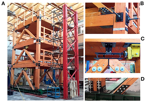
Figure 4. (A) Experimental model of post-tensioned timber frame building with dissipative V-inverted bracing systems. Details of bracing connections to (B) beam-column joint; (C) UFP and beam; (D) foundation.
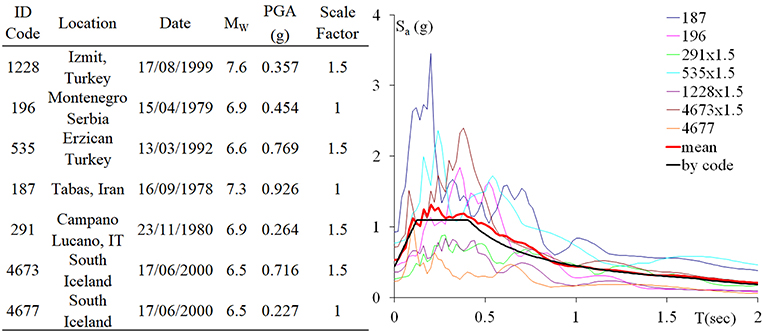
Figure 5. Main characteristics of selected earthquakes.
In order to assess for the influence of different amounts of energy dissipated by additional systems on the seismic response, the experimental model has been designed, and tested in different configurations (Di Cesare et al., 2017), varying the re-centering ratio: (i) βF = 0 bare post-tensioned frame (F); (ii) βF = 0.4 with dissipative rocking mechanisms (D) at beam-column and column-foundation connections; and (iii) βF = 0.8 with dissipative bracing systems (F+DB = BF). In this paper the results of the bare post-tensioned frame (F), related to the free-rocking condition, and of the braced post-tensioned frame (BF) are compared. More details on the results of the dissipative rocking (D) configuration are reported in Di Cesare et al. (2014).
The dissipative bracing system selected for the experimental model consisted of two V-inverted dissipative braces for each story, installed within the bays of the two parallel frames along the testing direction, as shown in Figure 4A. The connection details of the bracing system are shown in Figures 4B–D.
The design spectrum has been defined considering a peak ground acceleration PGA of 0.44 g and medium soil class according to Eurocode1. The seismic inputs consisted of seven spectra-compatible earthquakes selected from the European strong motion database (Figure 6). The testing program of all configurations is summarized in Table 1.
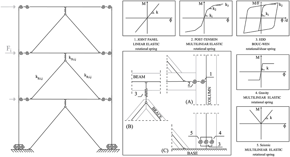
Figure 6. Numerical modeling of the braced post-tensioned frame and details adopted for rocking connections (beam-column and column-foundation) and for dissipative bracing systems.
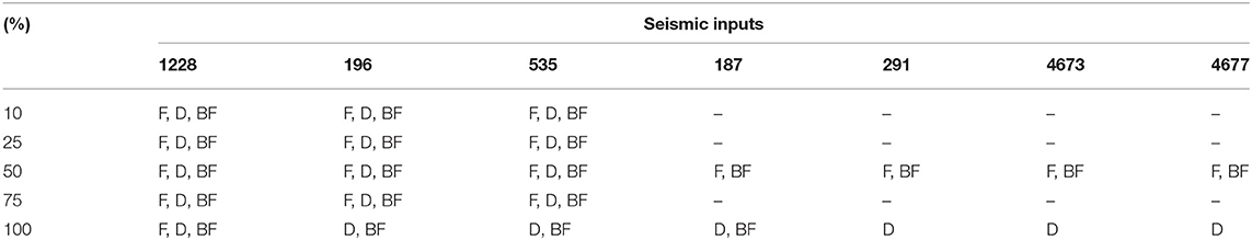
Table 1. Testing program of bare frame (F), with dissipative rocking (D), and with dissipative braces (BF).
The seismic response of the experimental model has been recorded by real-time monitoring through a combination of 54 instruments, including displacement potentiometers, load cells, and accelerometers. Displacement potentiometers and load cells have been used for monitoring the force-displacement behavior of all UFP dampers at each story for both sides of the braced model. During the experimental campaign, the intensity of the seismic inputs was progressively increased in acceleration for earthquakes 1,228, 196, and 535, from 10 to 100% of PGA, in order to provide additional information about the seismic performance frame response at varying levels of ground shaking (Table 1). In the case of braced post-tensioned frame configuration (BF) one UFP damper at the first story of the bracing system (UFP1) reached the failure condition during testing ID 187 at 100% of PGA level due to cyclic fatigue after almost 40 tests and more than 150 cycles to ductility μDB > 2 sustained by the device (Ponzo et al., 2019). For the bare frame configuration (F) the PGA level was increased up to 75% because an imposed interlock of 2.5% of maximum inter-story drift was reached, except for the weaker earthquake input 1,228, at 100% of PGA (see Table 1).
Numerical Model
The non-linear numerical model of the test frame has been implemented using SAP2000 finite element software based on the lumped plasticity approach, which uses elastic timber elements connected with non-linear elements representing plastic connections of the system (Figure 6). The constitutive laws of connections elements are represented in Figure 6.
The beam to column joints was modeled combining two rotational springs in parallel (detail A of Figure 6), representative of the flexibility of the joint panel (elements 1 of Figure 6), and the post-tensioning (elements 2 of Figure 6). The non-linear force-displacement hysteretic behavior of the UFP dampers was modeled by using non-linear shear link elements connecting the elastic beam and V-inverted braces (detail B of Figure 6) characterized by the Bouc-Wen cyclic laws (element 3 of Figure 6; Bouc, 1967; Wen, 1980). Three rotational springs have been implemented at the column to base connections (detail C of Figure 6), representative of the moment resistance due to gravity load (elements 4 of Figure 6), seismic load (elements 5 of Figure 6), and dissipative steel angles (elements 3 of Figure 6). More details about numerical modeling of the bare and braced frame are reported in Ponzo et al. (2018) and Di Cesare et al. (2019b).
Design of Dissipative Bracing System
A step by step design procedure has been applied for the design of the experimental post-tensioned braced model.
Step 1. The design procedure at the design considered earthquake (PGA 100%) starts from the assumption of the design displacement Δu = 58 mm or drift θd = 1.25%.
Step 2. The post-yield stiffness ratio r = 0.2, the displacement ductility μ = 2.5 and the re-centering ratio of the braced system βF = 0.8 have been assumed in order to define the basic flag-shape system.
Step 3. The equivalent viscous damping ξeqvs. displacement ductility μ is plotted in Figure 7A considering an elastic viscous damping ξeq,v = 2% and a reduction factor k = 0.85 for the hysteretic damping ξeq,h,v.
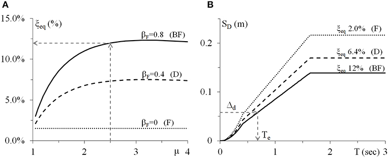
Figure 7. (A) Equivalent viscous damping vs. ductility of post-tensioned timber structures for different re-centering ratios; (B) Design displacement response spectrum.
Step 4. The equivalent period Te of the SDOF braced frame can be derived from the design displacement response spectrum (Figure 7B) reduced by the damping correction factor 3. As highlighted, when equivalent viscous damping increased from the post-tensioned frame to the braced frame, the design displacement substantially reduced. The equivalent stiffness Ke, the yield force Fy and ultimate force Fu of the structure have been evaluated by Equation (5).
Step 5. From the flag-shape behavior, the characteristics of the equivalent bare frame and of the equivalent dissipative bracing system have been calculated using Equation (6) and Equation (7). The main design results from step 1 to step 5 are summarized in Figure 8 in terms of force-displacement of the equivalent SDOF systems compared with the seismic design demand.
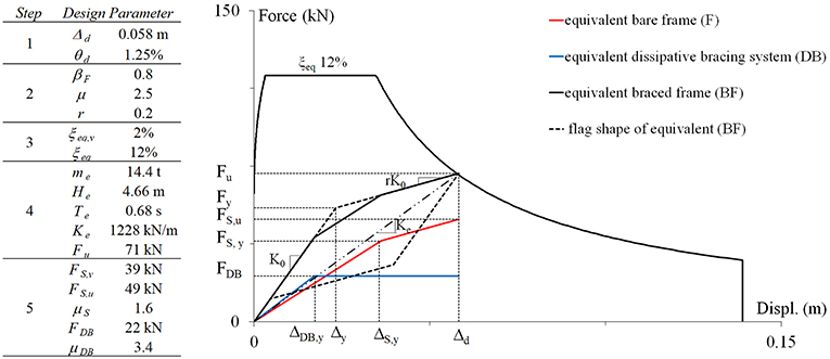
Figure 8. Results of the design procedure applied to the Pres-Lam experimental model with dissipative bracing systems.
Step 6.1. The equivalent force and stiffness of the bare frame (F) have been distributed up to the stories (kS, i, FS,y,i) and the post-tensioning resistant moments MPT have been evaluated through the MMBA method (Newcombe et al., 2008). For the experimental model the design of post-tensioning force was 100 kN for the primary direction and 50 kN for the secondary direction. The section sizes of columns were 200 × 320 mm while primary and secondary beams were 200 × 305 mm and 200 × 240 mm, respectively (Ponzo et al., 2012).
Step 6.2. Two V-inverted chevron braces for each story (nDB,i = 2) both compounded by two linear elastic timber braces (B) in series with the elasto-plastic damper (D) composed the DB system, see Figure 6. The force and stiffness of the equivalent DB system have been distributed up to the stories (kDB,i, FDB,i) and in the plan, then the characteristics of the single dissipating brace kDB,i,j, FDB,i,j were defined. The main results of the design are summarized in Table 2A.
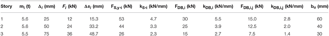
Table 2A. Characteristics of the braced post-tensioned frame.
U-shaped Flexural steel Plates (UFPs) have been selected as dampers in order to comply with the force requirement at each story without changing the gravity load distribution on beams and columns and reducing the influence on the post-tensioned beam-column joints.
Each elasto-plastic damper (D) is composed of two UFPs placed between the bottom surface of the principal beam and the supporting timber rods (B) having a cross section of 160 × 180 mm (Figure 4C).
In the hypothesis of rigid bracing truss and flexural UFP dampers (kB,i,j >> kD,i,j), the stiffness kDi,j of the damper corresponds to the stiffness kDB,i,j of the jth dissipative brace at the ith story (kD,i,j ≅ kDB,i,j). The design of the UFPs made of C60 stainless steel was performed by fixing geometrical diameter (Du = 60 mm) and thickness (tu = 6 mm) and varying the width bu at each floor, as reported in Table 2A.
Quasi-static displacement controlled cyclic was performed up to the expected inter-story displacement (μD > 3) in order to characterize the UFP dampers' behavior. Figure 9 shows the force-displacement behavior of experimental quasi-static tests performed on the UFP dampers designed and installed at each story of the braced frame compared with the results of the design procedure. The experimental results show that the design assumptions are consistent with the actual UFP dampers' behavior. Stable hysteretic behavior, without any sign of failure, has been observed during cyclic loading, maintaining almost the same energy dissipation capability. For more details about the design and testing of UFP dampers, please refer to Ponzo et al. (2019). The proposed procedure is valid also for shear link devices, such as those proposed by Nuzzo et al. (2018), as an alternative to UFP dampers if they do not modify the pattern of vertical loads in the beam. The design assumptions have been verified through non-linear time history analyses performed considering the numerical model of Figure 6 and the input motions of Figure 5, as reported in the following paragraph.
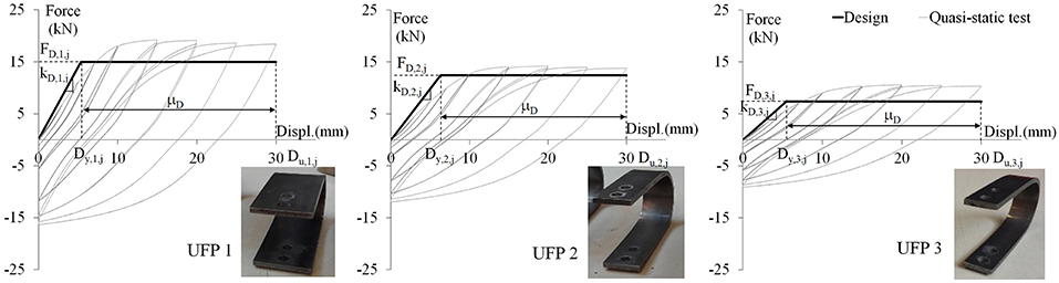
Figure 9. Force-displacement of the UFP dampers at the three story.
Results and Validation of the Design Procedure
In Figure 10, the comparison between experimental tests performed on the bare frame (F) and braced frame (BF) is shown in terms of maximum story drifts and maximum story accelerations for all PGA intensity levels. The values of drift of the BF at higher PGA levels (50, 75, 100%) are significantly reduced in respect to the bare frame (F), while at lower PGA intensities (10, 25%), especially for seismic inputs 1228 and 196, similar values have been experienced. The maximum accelerations of BF show some increase, in particular at the first floor, compared to the F configuration. Generally, the introduction of the hysteretic DB system allows the reduction of the total drift with a slight increase of story acceleration.
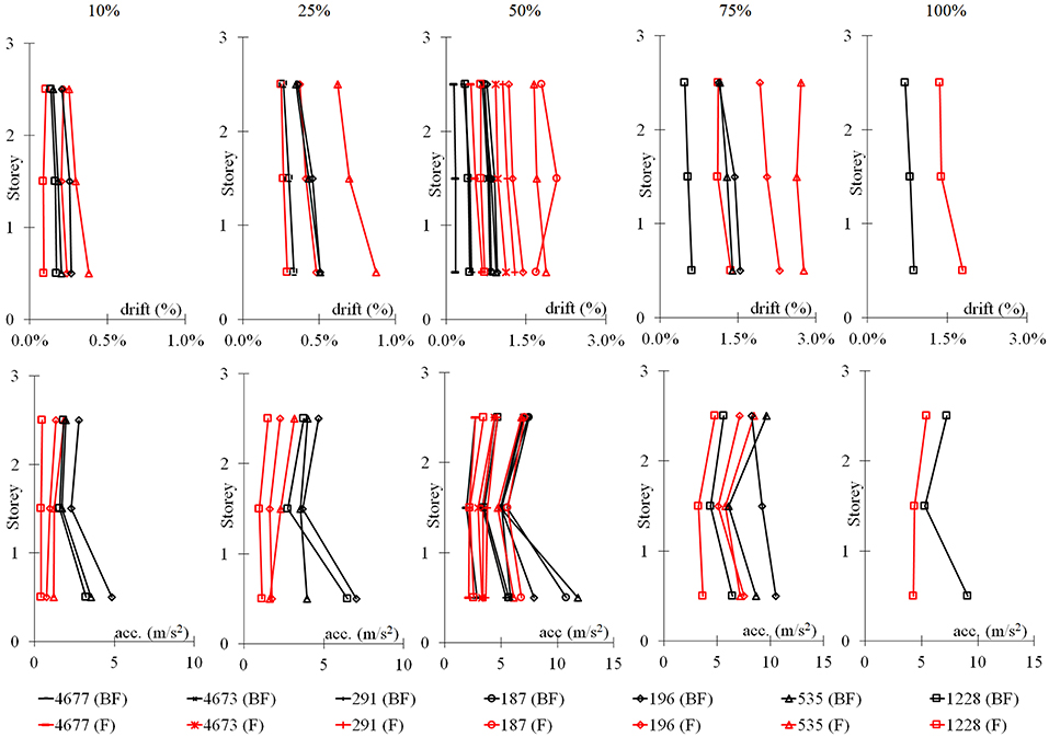
Figure 10. Maximum inter-story drift and maximum acceleration at each story from all experimental tests.
In order to show the effectiveness of the DB system, the experimental global results of the BF model have been compared with the results of F for seismic inputs 1228, 196, and 535 at 75% of the PGA level. Figure 11 shows the time histories of base shear and total drift and of total drift vs. corresponding base shear. As can be observed, the global flag shape behavior of both models (F and BF) is highlighted for stronger earthquakes 196 and 535. Due to the stiffening contribution of the dissipative bracing system, the values of base shear increase when DB is added to the bare frame at about 30%, as assumed in the design procedure (Figure 8).
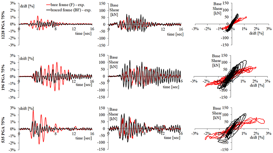
Figure 11. Experimental results for (F) and (BF) obtained for seismic inputs 1228, 196, and 535 at 75% of PGA: time-histories of base shear and total drift and base shear vs. total drift.
In order to simulate the experimental results of BF, non-linear dynamic analyses at 100% of PGA level have been carried out for the complete set of the seismic inputs. The comparisons between numerical and experimental results obtained for seismic inputs 1228, 196, and 535 are reported in Figure 12 in terms of global behavior and local response of UFP dampers at each story. The numerical simulations are in good agreement with experimental results, and the UFPs' cyclic behaviors were reliably predicted. Only a few discrepancies can be observed on the peak values of base shear and on the maximum ductility of UFPs in the case of seismic input 196. The comparison between experimental and numerical results of the braced frame tested at 100% of PGA is summarized in Table 2B. The values of equivalent damping have been estimated as a fraction of the critical damping, as reported in Smith et al. (2014).
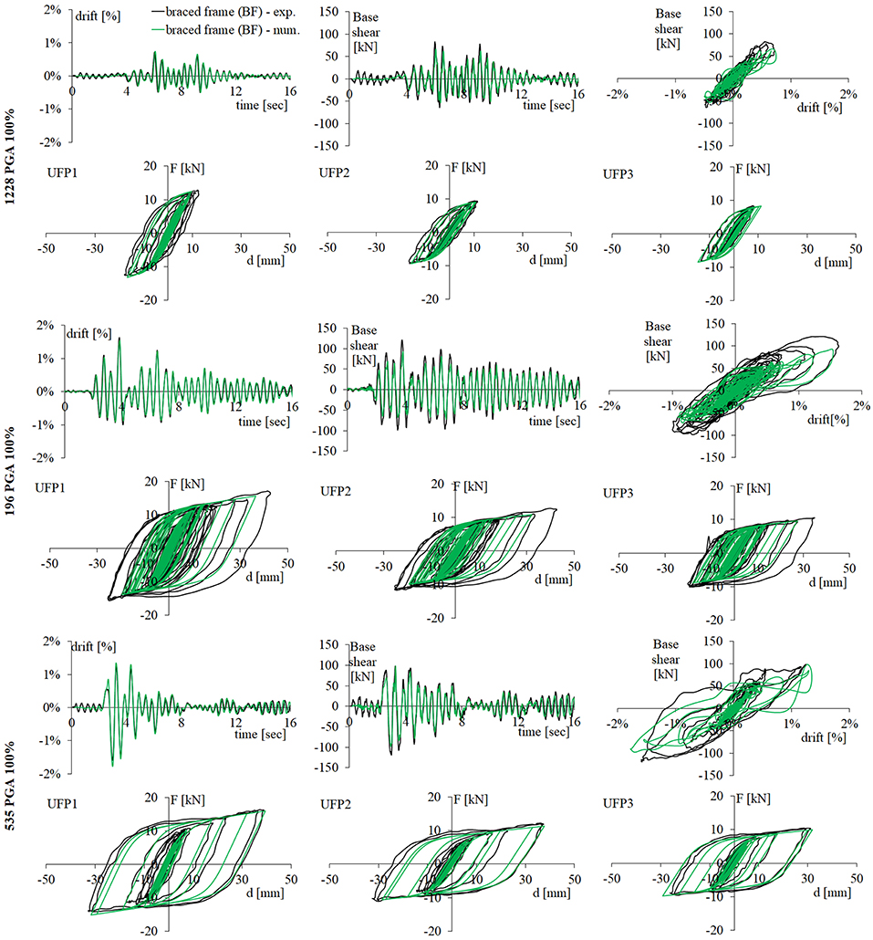
Figure 12. Experimental and numerical results of BF model obtained for seismic inputs 1228, 196, and 535 at 100% of PGA: time-histories of base shear and total drift, base shear vs. total drift and hysteretic cyclic behavior of UFPs.
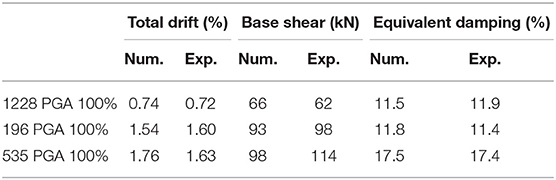
Table 2B. Experimental and numerical results at PGA 100%.
The design assumptions used for the BF model (Figure 8) have been validated through comparison with the experimental and numerical outcomes. The equivalent SDOF system obtained from design procedure of F and BF models compared with the acceleration-drift response spectrum format are plotted in Figure 13. The experimental total drift (i.e., maximum top displacement normalized by height of the structure) vs. corresponding accelerations (i.e., base shear divided by the equivalent mass) recorded at different PGA levels are reported in Figure 13A for the F model and in Figure 13B for the BF model.
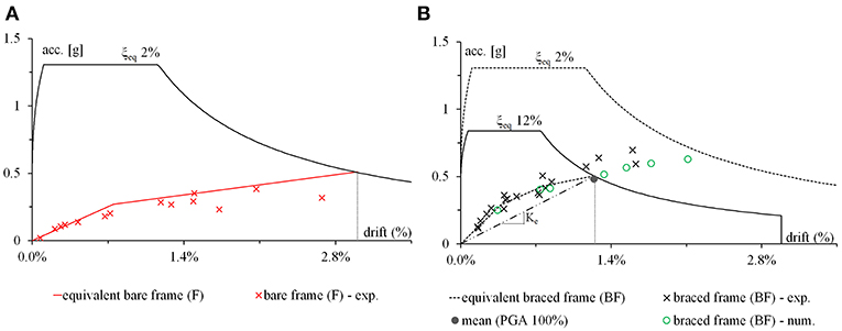
Figure 13. Comparison between design results and experimental peak values in (A) free-rocking configuration and (B) dissipative bracing configuration of Pres-Lam experimental model.
The numerical results of non-linear dynamic analyses carried out on the BF model for all seismic inputs at 100% of PGA level have been compared with the target displacement Δd or drift θd assumed in the design procedure (dashed vertical line at 1.25%) in Figure 13B.
As can be observed, the mean value of numerical drift (averaged on seven earthquakes) was accurately predicted by the design target drift θd, as a verification of the design procedure (Step 7 of design method). From Figure 13 it can be pointed out that the seismic response of the BF model at the DBE (100% of PGA) reduces the inter-story drift θd more than twice if compared with the response of model F (from 3 to 1.25%). This effect is mainly due to the increase of the equivalent damping ξeq (from 2 to 12%) and of the equivalent stiffness Ke (from 513 to 1228 kN/m). Moreover, the drift increase with an increasing PGA level of seismic inputs and the equivalent SDOF systems provides a reliable representation of the experimental results in both configurations (F and BF models).
Conclusions
In this paper, a displacement-based design procedure for post-tensioned timber framed buildings with dissipative-bracing systems has been described and applied to a three-dimensional, 2/3 scaled, three-story prototype experimental model. Several shaking table tests have been performed at the structural laboratory of the University of Basilicata (Italy) on different configurations of the experimental model: bare frame (F) and braced frame (BF). The dissipating bracing (BD) system considered in this application consisted of V-inverted braces (B) composed of two timber rods and a hysteretic damper (D) realized with two UFPs, with two braces for each story.
In order to investigate the effectiveness of the energy dissipating bracing system on controlling the seismic response of the post-tensioned timber frame, the experimental results of the braced frame (BF) and the bare frame (F) have been compared. The bare frame (F) and the braced frame (BF) performed as expected with the global flag-shaped behavior observed at the design levels of seismic inputs. The dissipative bracing system improved the seismic response of the experimental model by reducing to 1.25% the experimental maximum drift at the design seismic level, ~60% less than the bare frame with an increase of 30% of the base shear. Moreover, the braced frame increases the secant stiffness more than 2-fold and the total equivalent viscous damping from 2 to 12%, in good agreement with the experimental and numerical damping estimations. No damage occurred to the structural elements throughout testing, with the application of almost 80 earthquakes in both configurations.
In order to validate the design procedure, the design assumptions have been compared with the shaking table test results and non-linear dynamic analysis carried out on the braced frame (BF) at PGA level of 100%. The numerical seismic response of the BF model and the local behavior of UFP dampers at each story have shown good agreement with experimental tests. The mean value of numerical drift (averaged on seven earthquake inputs) was very close to the design assumption, showing the reliability of the design procedure.
Data Availability
The datasets generated for this study are available on request to the corresponding author.
Author Contributions
FP has contributed to the construction technology development and to the international collaboration with other research institutions. AD has designed the experimental specimen and the testing apparatus. DN has organized the experimental shaking table tests. NL has performed the numerical analyses and processed analytical results. All authors have contributed to manuscript revision, read, and approved the submitted version.
Conflict of Interest Statement
The authors declare that the research was conducted in the absence of any commercial or financial relationships that could be construed as a potential conflict of interest.
Acknowledgments
The authors would like to acknowledge the financial support of the RELUIS 2014-2018 project, funded by the Italian Civil Protection Department, and Prof. Stefano Pampanin from University of Canterbury, Christchurch, NZ for his contribute to the research study.
Footnotes
1. ^EN 1998-1. (2003). Design of Structures for Earthquake Resistance - Part 1: General Rules, Seismic Actions and Rules for Buildings. European Committee for Standardization.
2. ^CNR-DT 206 R1/2018. Istruzioni per la Progettazione. l'Esecuzione ed il Controllo delle Strutture di Legno.
3. ^D.M. 17/01/2018. Norme Tecniche per le Costruzioni (NTC 2018). Gazzetta Ufficiale, n. 42 del 20/02/2018, Supplemento ordinario n.8.
References
Bouc, R. (1967). “Forced vibration of mechanical system with hysteresis,” in 4th Conference on Nonlinear Oscillations (Prague).
Buchanan, A. H., Deam, B., Fragiacomo, M., Pampanin, S., and Palermo, A. (2008). Multi-story prestressed timber buildings in New Zealand. J. Int. Assoc. Bridge Struct. Eng. 18, 166–173. doi: 10.2749/101686608784218635
Di Cesare, A., Ponzo, F. C, Nigro, D., Dolce, M., and Moroni, C. (2012). Experimental and numerical behaviour of hysteretic and visco-recentring energy dissipating bracing systems. Bull. Earthquake Eng. 10,1585–1607. doi: 10.1007/s10518-012-9363-x
Di Cesare, A., and Ponzo, F. C. (2017). Seismic retrofit of reinforced concrete frame buildings with hysteretic bracing systems: design procedure and behaviour factor. Shock Vibr. 2017:2639361. doi: 10.1155/2017/2639361
Di Cesare, A., Ponzo, F. C., Lamarucciola, N., and Nigro, D. (2019b). “Modelling of post-tensioned timber framed buildings with hysteretic bracing system: preliminary analysis,” in IOP Conference Series: Earth and Environmental Science, Vol. 233 (IOP Publishing), 022026. doi: 10.1088/1755-1315/233/2/022026
Di Cesare, A., Ponzo, F. C., and Nigro, D. (2014). Assessment of the performance of hysteretic energy dissipation bracing systems. Bull. Earthquake Eng. 12, 2777–2796. doi: 10.1007/s10518-014-9623-z
Di Cesare, A., Ponzo, F. C., Nigro, D., Pampanin, S., and Smith, T. (2017). Shaking table testing of post-tensioned timber frame building with passive energy dissipation systems. Bull. Earthquake Eng. 15, 4475–4498. doi: 10.1007/s10518-017-0115-9
Di Cesare, A., Ponzo, F. C., Pampanin, S., Smith, T., Nigro, D., and Lamarucciola, N. (2019a). Displacement based design of post-tensioned timber framed buildings with dissipative rocking mechanism. Soil Dynamics Earthquake Eng. 116, 317–330. doi: 10.1016/j.soildyn.2018.10.019
Estévez-Cimadevila, J., Otero-Chans, D., Martín-Gutiérrez, E., and Suárez-Riestra, F. (2016). Long-span wooden structural floors with self-tensioning system: performance under asymmetrical loads. Adv. Mater. Scie. Eng. 2016:3696025. doi: 10.1155/2016/3696025
Federal Emergency Management Agency (2012). Seismic Performance Assessment of Buildings Vol. 1—Methodology. Technical report FEMA-P58, Washington, DC.
Krawinkler, H., and Moncarz, P. D. (1981). Theory and Application of Experimental Model Analysis in Earthquake Engineering. Standford, CA: NASA STI/Recon Technical Report N 82.
Lin, Y. Y., Tsai, M. H., Hwang, J. S., and Chang, K. C. (2003). Direct displacement-based design for building with passive energy dissipation systems. Eng. Struct. 25, 25–37. doi: 10.1016/S0141-0296(02)00099-8
Mazza, F., and Mazza, M. (2019). Seismic retrofitting of gravity-loads designed rc framed buildings combining CFRP and hysteretic damped braces. Bull. Earthquake Eng. 13, 1–23. doi: 10.1007/s10518-019-00593-5
Newcombe, M. P., Marriott, D., Kam, W. Y., Pampanin, S., and Buchanan, A. H. (2011). “Design of UFP-coupled post-tensioned timber shear walls,” in 9th Pacific Conference on Earthquake Engineering (Auckland).
Newcombe, M. P., Pampanin, S., Buchanan, A., and Palermo, A. (2008). Section analysis and cyclic behavior of post-tensioned jointed ductile connections for multi-story timber buildings. J. Earthquake Eng. 12, 83–110. doi: 10.1080/13632460801925632
Newcombe, M. P., Pampanin, S., and Buchanan, A. H. (2010). “Design, fabrication and assembly of a two-story post-tensioned timber building,” in Proc. World Conference on Timber Engineering (Riva del Garda), 3092–3100.
Nuzzo, I., Losanno, D., and Caterino, N. (2019). Seismic design and retrofit of frame structures with hysteretic dampers: a simplified displacement-based procedure. Bull. Earthquake Eng. 17, 1–33. doi: 10.1007/s10518-019-00558-8
Nuzzo, I., Losanno, D., Caterino, N., Serino, G., and Rotondo, L. M. B. (2018). Experimental and analytical characterization of steel shear links for seismic energy dissipation. Eng. Struct. 172, 405–418. doi: 10.1016/j.engstruct.2018.06.005
Pei, S., Popovski, M., and van de Lindt, J. W. (2012). “Performance based design and force modification factors for CLT structures,” in Proceeding of the 45th Meeting, International Council for Research and Innovation in Building and Construction, Working Commission W18 – Timber Structures, CIB-W18 (Växjö), 2012.
Polocoşer, T., Leimcke, J., and Kasal, B. (2018). Report on the seismic performance of three-dimensional moment-resisting timber frames with frictional damping in beam-to-column connections. Adv. Struct. Eng. 21, 1652–1663. doi: 10.1177/1369433217753695
Ponzo, F. C., Di Cesare, A., and Lamarucciola, N. (2018). Modelling of post-tensioned timber-framed buildings with seismic rocking mechanismat the column-foundation connections. Int. J. Comput. Methods Exp. Meas. 5, 966–978. doi: 10.2495/CMEM-V5-N6-966-978
Ponzo, F. C., Di Cesare, A., Lamarucciola, N., and Nigro, D. (2019). Testing requirements of hysteretic energy dissipating devices according to the new Italian seismic code. Compdyn 2019, 24-26 June, Crete, Greece.
Ponzo, F. C., Smith, T., Di Cesare, A., Pampanin, S., Carradine, D., and Nigro, D. (2012). “Shaking table test of a multistory post-tensioned glulam building: design and construction,” in World Conference on Timber Engineering WCTE (Auckland), 44–52.
Priestley, M. J. N. (2000). Performance-Based Seismic Design. Keynote Address, 12-WCEE, Auckland, p. 22.
Priestley, M. J. N., Calvi, G. M., and Kowalsky, M. J. (2007). Displacement-Based Seismic Design of Structures. Pavia: IUSS Press, 670.
Priestley, M. J. N., and Grant, D. N. (2005). Viscous damping in seismic design and analysis. J. Earthquake Eng. 9, 229–255. doi: 10.1142/S1363246905002365
Priestley, N., Sritharan, S., Conley, J., and Pampanin, S. (1999). Preliminary results and conclusions, PRESSS five-story precast concrete test building. PCI J. 44, 42–67. doi: 10.15554/pcij.11011999.42.67
Pu, W., Liu, C., and Dai, F. (2018). Optimum hysteretic damper design for multi-story timber structures represented by an improved pinching model. Bull. Earthquake Eng. 16, 6221–6241. doi: 10.1007/s10518-018-0437-2
Smith, T., Ponzo, F. C., Di Cesare, A., Pampanin, S., Carradine, D., Buchanan, A. H., et al. (2014). Post-tensioned glulam beam-column joints with advanced damping systems: testing and numerical analysis. J. Earthquake Eng. 18, 147–167. doi: 10.1080/13632469.2013.835291
Structural Timber Innovation Company Inc (2013). Post-Tensioned Timber Buildings - Design Guide, Structural Timber Innovation Company. Christchurch.
Ugalde, D., Almazán, J. L., Santa María, H., and Guindos, P. (2019). Seismic protection technologies for timber structures: a review. Eur. J. Wood Wood Prod. 77, 173–194. doi: 10.1007/s00107-019-01389-9
Wang, B., and Zhu, S. (2018). Seismic behavior of self-centering reinforced concrete wall enabled by superelastic shape memory alloy bars. Bull. Earthquake Eng. 16, 479–502. doi: 10.1007/s10518-017-0213-8
Wen, Y. K. (1980). Equivalent linearization for hysteretic systems under random excitation. J. Appl. Mech. 47, 150–154. doi: 10.1115/1.3153594
Keywords: post-tensioned timber building, dissipative bracing systems, displacement-based design, shaking table tests, non-linear dynamic analysis
Citation: Ponzo FC, Di Cesare A, Lamarucciola N and Nigro D (2019) Seismic Design and Testing of Post-tensioned Timber Buildings With Dissipative Bracing Systems. Front. Built Environ. 5:104. doi: 10.3389/fbuil.2019.00104
Received: 12 July 2019; Accepted: 21 August 2019;
Published: 06 September 2019.
Edited by:
Dario De Domenico, University of Messina, ItalyReviewed by:
Daniele Losanno, Istituto per le tecnologie della costruzione (ITC), ItalyMarco Furinghetti, University of Pavia, Italy
Copyright © 2019 Ponzo, Di Cesare, Lamarucciola and Nigro. This is an open-access article distributed under the terms of the Creative Commons Attribution License (CC BY). The use, distribution or reproduction in other forums is permitted, provided the original author(s) and the copyright owner(s) are credited and that the original publication in this journal is cited, in accordance with accepted academic practice. No use, distribution or reproduction is permitted which does not comply with these terms.
*Correspondence: Antonio Di Cesare, YW50b25pby5kaWNlc2FyZUB1bmliYXMuaXQ=