 Kangkang Wang1
 Kailai Deng
 Canhui Zhao
- 1Department of Bridge Engineering, Southwest Jiaotong University, Chengdu, China
- 2Municipal Engineering and Research Design Institute, Chengdu, China
Ultra-high-performance Concrete (UHPC) has a wide range of potential civil engineering applications, owing to its excellent mechanical properties and durability. To investigate the bending behavior of reinforced UHPC components, nine reinforced UHPC deck specimens were tested by conducting four-point bending experiments. The crack development, load-carrying capacity, and strain distribution were observed, and the tests results revealed that the introduction of steel fibers into UHPC obviously improved the structure's toughness and crack resistance. Based on the tests results, a theoretical formula was derived for calculating the bending stiffness of the UHPC decks during the entire loading process, which was divided into three representative stages based on the initial cracking and yielding. The results for the load-deflection response obtained by the formulas are in good agreement with the experimental results.
Introduction
Steel-concrete composite beams are the most widely used beams in bridge engineering projects (Nie et al., 2019). In recent decades, these structures rapidly improved and resulted in obvious economic benefits (Chafaie and Portier, 2004). However, the durability of composite bridges is facing significant challenges, such as fatigue under vehicle induced vibration (Zhang et al., 2016), concrete carbonization (Tesfamariam et al., 2018), and chloride-induced corrosion of the steel rebar (Marsavina et al., 2009; OŽbolt et al., 2010; Sajedi et al., 2016). Many studies have attempted to improve the serviceability of composite beams. Some high-performance concretes with fiber-reinforced polymer have been employed in composite beams to prevent the corrosion of steel rebar and improve weather resistance (Tian et al., 2017). In recent years, remarkable progress has been made in the development of ultra-high-performance concrete (UHPC). Its mechanical properties, such as the compressive and tensile strength, and elastic modulus, have been significantly enhanced while the cost has substantially reduced (Wang et al., 2018). Using UHPC in composite beams can be a good solution to the durability problem and an effective approach toward economic design. For example, the introduction of reactive powder concrete (RPC) enhances the stiffness of a composite beam to reduce the fatigue stress amplitude of its components (Cao et al., 2017). UHPC applications greatly contribute to the prefabrication and assembly of composite bridges with excellent mechanical properties (Wang et al., 2019). Moreover, UHPC has been used as the wet joint material to enhance a composite beam's crack resistance, which is closely related to the reinforcement ratio of the cross-section (Zhao et al., 2018). The abovementioned studies have demonstrated the effectiveness of steel-UHPC composite beams. Unlike typical concrete, UHPC is known for its high durability, high workability and high strengths, which is called the twenty-first century concrete. In the current construction of the infrastructures, with the development of green and environment-friendly concrete engineering materials, UHPC plays an active role in improving the economic efficiency and solving difficult engineering problems. However, the excellent mechanical properties are accompanied by the expensive price, which is also a major obstacle to widespread application of UHPC. In order to reduce the expense of UHPC, the coarse aggregates are introduced in UHPC, which can also reduce the impact of the shrinkage strain to a certain degree. Moreover, the introduction of the steel fibers brings outstanding tensile strength and the characteristics of strain hardening for UHPC, also called UHPFRC (Ultra-High Performance Fiber Reinforced Concrete), which is particularly inaccordance with the ordinary concrete. Therefore, it is necessary to consider the contribution of UHPC tensile capacity for the calculation of the bending capacity. At present, few researches were completed in this aspect and the load-carrying capacity of the reinforced UHPC with coarse aggregates has not been explored. Based on the above consideration, in order to develop the theoretical method for calculating the bending capacity of reinforced UHPC, which considers the contribution of the tensile strength of UHPC, three sets of reinforced UHPC with coarse aggregates deck specimens with different reinforced ratios were designed and tested. The crack development, load-bearing capacity, failure mode, and strain distribution of the concrete and steel rebar were measured. Based on the test results, a theoretical formula for calculating the flexural stiffness of the UHPC deck was derived with consideration to the contribution of the tensile capacity of the UHPC at different cracking stages.
Experiment
Specimen Design
Three sets of reinforced UHPC deck specimens were designed and labeled as Set A, Set B, and Set C. Each set comprised three identical specimens. As shown in Figure 1 and Table 1, all specimens had the same overall dimensions: length of 1,500 mm, width of 350 mm, and depth of 160 mm. The specimens in each set employed the same sectional reinforcement. In Set A, the specimens adopted 12 longitudinal φ-16 rebar with a diameter of 16 mm, while Set B adopted eight φ-18 rebar, and Set C adopted eight φ-20 rebar. The cross-sectional ratios were 2.46, 2.08, and 2.56% for the specimens in Set A, Set B, and Set C, respectively. All specimens had a cover layer with a thickness of 20 mm. The φ-10 rebar was transversely placed with a spacing of 100 mm.
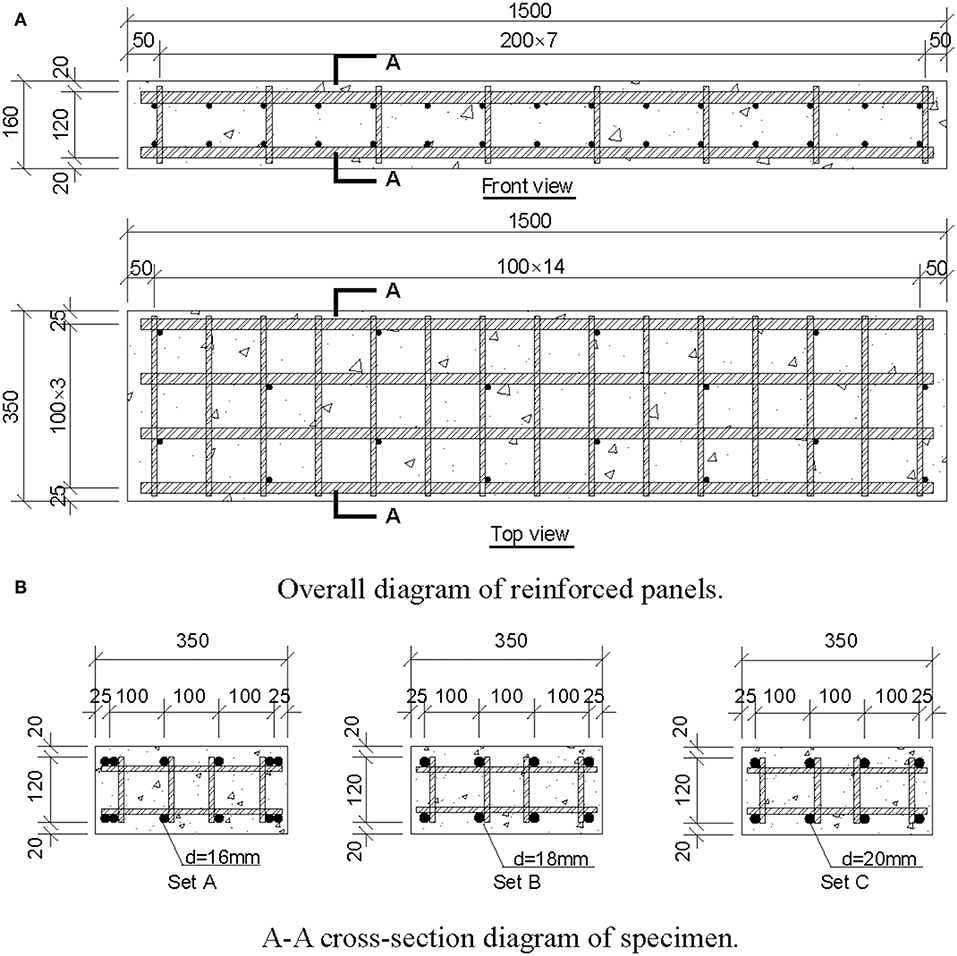
Figure 1. Design of specimens (unit: mm). (A) Overall diagram of reinforced panels. (B) A-A cross-section diagram of specimen.
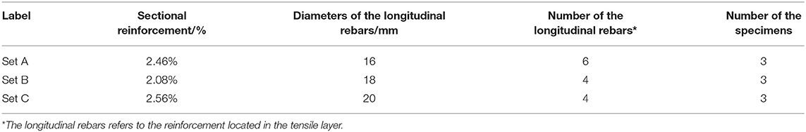
Table 1. Parameters design of the reinforced UHPC panel specimens.
Loading Setup and Measuring System
Standard four-point bending tests were carried out as shown in Figure 2. The roller supports were arranged at a distance of 1,200 mm. A stiff loading beam can distribute the load from a forced controlled jack to the specimens. The distance between the two loading points was 400 mm. During the loading process, the applied load of each jack was increased in 10 kN intervals over 60 s. Then, the loading force of each step was held for 2 min to measure the crack width and collect data. Two displacement transducers were arranged to monitor the mid-span deflection. As shown in Figure 3A, three concrete strain gauges were uniformly arranged on the top and bottom surface at the mid-span section. Three concrete strain gauges were pasted onto the surface of each specimen side to measure the movement of the sectional neutral axis.
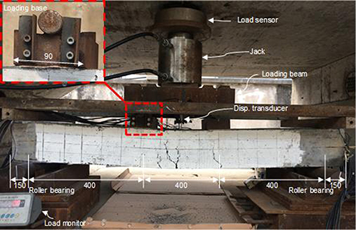
Figure 2. Specimen loading system (unit: mm).
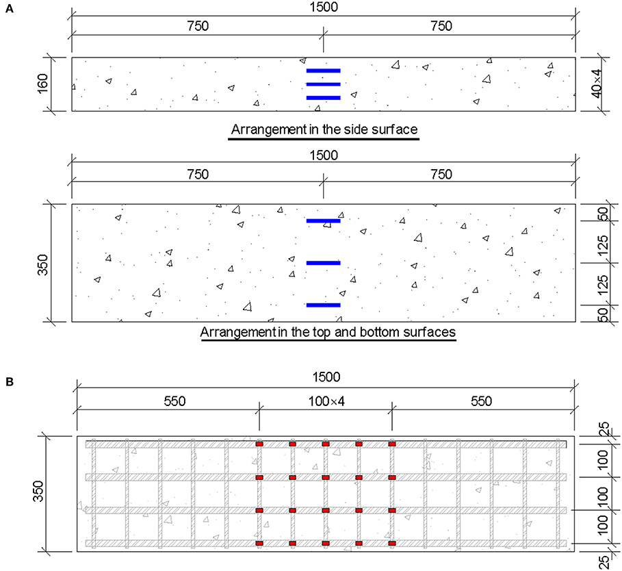
Figure 3. Arrangement of strain gauges on specimens: (A) concrete surface; (B) steel rebar (unit: mm).
In the pure bending segment, five strain gauges were attached to each longitudinal tensile rebar, as shown in Figure 3B, with a spacing of 100 mm to monitor the strain development of the steel rebar. The crack development was measured at each loading level using a digital crack observer.
Material Properties
The mix proportions and mechanical properties of UHPC are listed in Table 2. Two types of steel fiber were used: 0.22- and 0.3-mm diameter fiber with a mass ratio of 4:6. The strength of the steel fiber was up to 2,000 MPa. After pouring, all specimens were placed in a continuous-heating moist environment wherein the temperature was maintained at 80°C ± 5°C for 48 h until the initial setting occurred. HRB400 rebar was used in the specimens, which had a nominal yielding strength of 400 MPa. The mechanical properties of these materials are listed in Table 3. The simplified constitutive UHPC and steel rebar model can be used to model the behavior of UHPC (Zhao et al., 2019). As shown in Figure 4, the compressive and tensile strain-stress curves of UHPC were simplified such that they had a linear relationship with the deformation before the peak value. The constitutive model of HRB400 was simplified as bilinear. After the yielding point, the elastic modulus of the steel rebar was equivalent to 1.8% of the initial value.
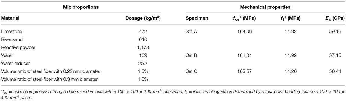
Table 2. Mix proportions and mechanical properties of UHPC.
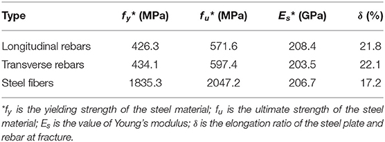
Table 3. Mechanical properties of HRB 400 rebar and steel fibers.
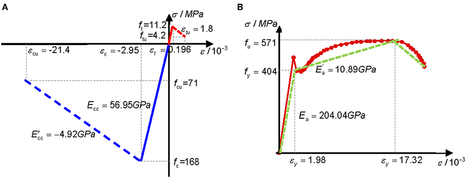
Figure 4. Constitutive material model: (A) UHPC; (B) HRB400.
Results
Crack and Failure Pattern
The crack distribution and ultimate failure modes of the UHPC decks are shown in Figure 5. There mainly existed five transverse cracks through the entire section. The crack that developed at the mid-span section was deeper in the UHPC panel. At the ultimate stage, the crack developed to three quarters of the depth of the entire section. When the steel fibers were completely pulled out from the UHPC matrix, the deck specimen lost its load-carrying capacity. At the upper side of the UHPC deck specimens, a compressive crush occurred after the reinforcement yielded.
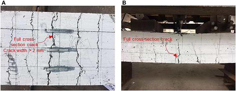
Figure 5. Crack distribution and failure model of reinforced UHPC panels: (A) bottom surface; (B) side surface.
The maximum crack width is shown in Figure 6A. The crack development for the UHPC reinforced deck specimen can generally be divided into three stages. The 1st stage is defined from the beginning to the initial cracking. The 2nd stage is the stable crack development stage characterized by the rapid development of numerous cracks. Here, a 10-kN increase corresponded to an increase of 0.2 mm in the crack width. The crack height on the side surface developed quickly and reached 70 mm, until the steel fiber restrained further crack height expansion. The 3rd stage is the rapid crack development stage, wherein the reinforcement in the tension area yielded. In the post-yielding stage, the bending stiffness of the specimen quickly decreased, which led to the rapid increase of the crack amount, width, and height. Finally, the steel fibers were pulled out of the UHPC matrix.
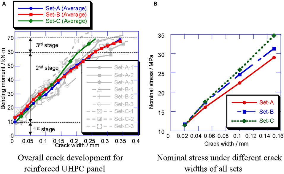
Figure 6. Crack development of all sets. (A) Overall crack development for reinforced UHPC panel. (B) Nominal stress under different crack widths of all sets.
To evaluate the crack resistance of the UHPC decks, the nominal tensile stress of the deck specimens was calculated as follows:
where I (= 1.43 × 108 mm4 in this case) is the overall sectional moment of inertia of the UHPC deck specimens; h is the thickness of the UHPC deck specimens; Mi is the moment of the mid-span section when the maximum crack width is up to i mm. The initial cracking and nominal tensile stresses corresponding to the crack widths of 0.05, 0.1, and 0.15 mm are shown in Figure 6B. The initial cracking strength of all reinforced UHPC deck specimens decreased to different degrees compared with the material properties listed in Table 2, because the reinforcement in the UHPC deck specimens damaged the integrity of the cement-based materials and introduced the initial defect, which eventually led to the decrease of the initial cracking stress. However, after cracking, the reinforcement sheared the bending moment of the UHPC deck specimens, and improved the crack resistance.
Load-Deflection Response
The load-deflection response at the mid-span section is shown in Figure 7. Similar to crack development, the load-deformation relationship can be divided into three stages. All specimens had similar bi-linear load-deflection responses. A slight inflection point was observed with a load of 50 kN, which corresponded to the initial cracking load. In the 2nd stage, the deflection maintained a linear growth relationship with the applied load until the reinforcement yielded. Moreover, the deflection rapidly increased in the post-yielding stage. As shown in Figure 8, specimens with different reinforcement ratios did not exhibit obvious differences with regard to bending stiffness.
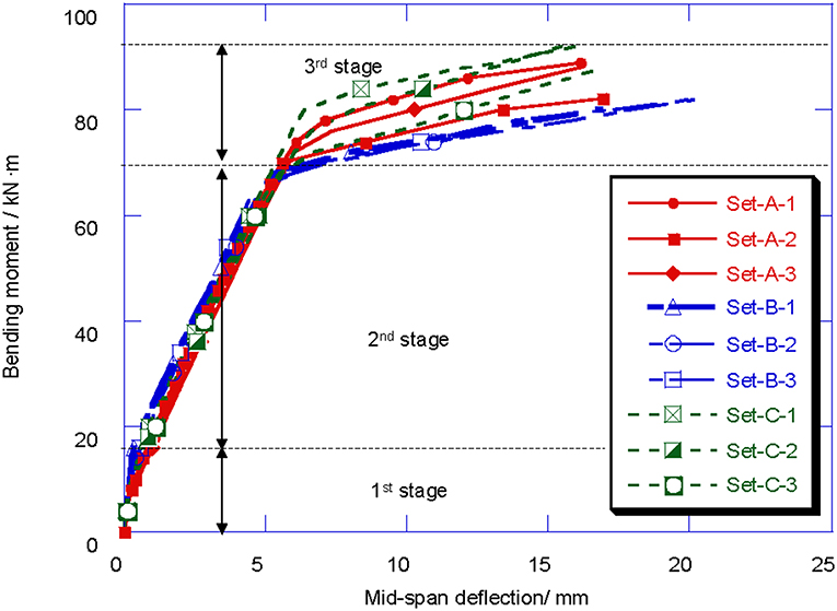
Figure 7. Load-deflection relationship of reinforced UHPC panels.
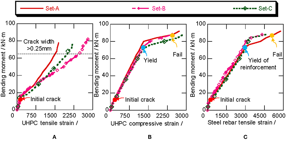
Figure 8. Strain development: (A) tensile strain of UHPC; (B) compressive strain of UHPC; (C) tensile strain of reinforcement.
Strain Distribution
Figure 8 shows the representative strain of the longitudinal steel rebar and concrete on the compressive and tensile surfaces of each set. As can be seen, the strain of both the tensile steel rebar and UHPC surface linearly increased before the initial cracking. However, an obvious inflection point occurred in the strain curves during cracking, owing the great impairment of the cross-section. After cracking, the strain of the tensile UHPC surface rapidly increased. However, when the crack width reached 0.25 mm, the strain gauges began incurring gradual damage, which resulted in incomplete stain monitoring. In the meantime, the stain distribution of the cross-section had entered a linear growth stage. When the tensile reinforcement strain reached 2,300 με, the reinforcement began to enter the yielding stage, wherein the strain growth rate of both the reinforcement and the UHPC compression surface obviously accelerated. Macroscopically, it was observed that the mid-span deflection of the specimen rapidly increased after the reinforcement yielded. Then, the compression strain of the UHPC reached 3,000 με, which is close to the failure condition. After one to two load levels, the specimen lost its bearing capacity and produced a clear cracking sound on the compressive surface of the UHPC. All tensile reinforcement yielded and the top surface of the UHPC almost collapsed.
Theoretical Estimation of Load-Carrying Capacity
Elastic Stage
Based on the experimental results, three formulas are proposed to describe the three stages of load-carrying capacity: the initial elastic stage, post-cracking stage, and post-yielding stage.
As shown in Figure 9A, he bending stiffness in the elastic stage was calculated as classic reinforced concrete using Equation (2), where b and h are the width and height of the section, respectively; The elastic modulus ratio of the UHPC reinforcement is the distance from the center of the reinforcement to the neutral axis.
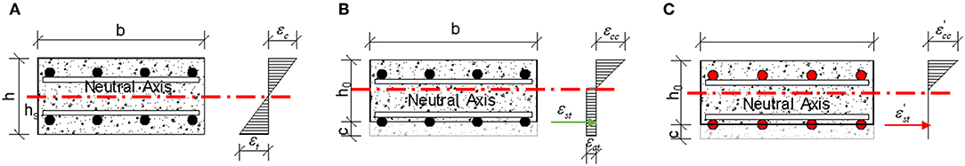
Figure 9. Section properties at different stress stages: (A) elastic stage; (B) post-cracking stage; (C) ultimate stage.
Post-cracking Stage
After the initial cracking, the location of the neutral axis moved upward, as shown in Figure 9B. The sectional flexural stiffness Bs is expressed by Equation (4), where ϕ is the sectional curvature under a plane-section assumption, εsm and εcm denote the tensile strain of the reinforcement and average compressive strain of the UHPC.
Considering the tensile strength of UHPC after the initial cracking, as shown in Figure 10. The sectional moment was as follows:
where Ms and Mt denotes the moments contributed by the reinforcement and the tensile UHPC to the center of the compressive region; Mc and denotes the moments contributed from the compressive and tensile UHPC to the center of the reinforcement; σst and σcc are the tensile stress of the reinforcement and compressive stress of the UHPC; ω is the equivalent coefficient of stress in the compression region of the UHPC.
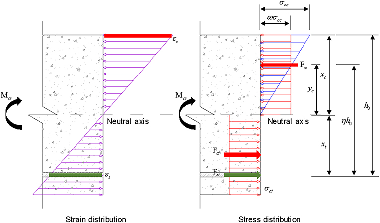
Figure 10. Strain distribution and stress distribution diagrams in post-cracking stage.
Meanwhile, considering the plasticity of the UHPC, ϕ can be obtained as follow:
According to Equations (3) and (5), Bs can be obtained as follows:
where ς (= ωνξη/ψc) is the average composite strain factor of the UHPC compression region.
According to the experimental strain data of steel rebars in Figure 11, Mt and can be obtained using (7), as follows:
Therefore, the bending stiffness of the cracking stage can be obtained as follows, which is improved by ~12% compared with the classical method of calculating typical reinforced concrete (RC) structures:
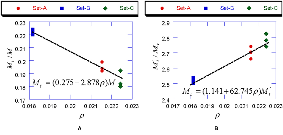
Figure 11. Fitting curve of Mt/M, /Mt and reinforcement ratio ρ: (A) Mt/M; (B) /Mt.
Ultimate Stage
In the ultimate stage, the UHPC lost its tensile capacity and the reinforcement yielded; that is Mt = = 0. As shown in Figure 9C, the reinforced UHPC deck degenerated into a typical reinforced concrete deck wherein the UHPC only provides compressive stress, while the tensile stress is provided by the reinforcement. According to the constitutive reinforcement model, the post-yielding elastic modulus was only ~5.34% of the initial elastic modulus. The sectional curvature ϕ was calculated as follows:
Then, the bending stiffness in the ultimate stage was calculated as follows:
Full-Range Stages of Bending Stiffness
In summary, the three different stages of the sectional bending stiffness are expressed by Equation (11), as follows:
The comparison between the calculated and experimentally obtained mid-span deflection values is presented in Figure 12. The theoretical formula could reasonably predict the load-deflection response, which demonstrates the effectiveness of Equation (11).
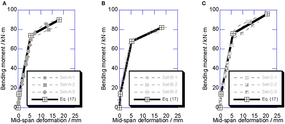
Figure 12. Comparison between calculated results and experimental results for load-deformation relationship: (A) Set A; (B) Set B; (C) Set C.
Conclusion
Nine deck specimens with three different reinforcement ratio sets were tested by applying standard four-point bending loads. The UHPC reinforced decks had excellent load-carrying capacity and crack resistance. The bending stiffness during the entire loading process was theoretically calculated based on the experimental results. The major conclusions drawn from this study are summarized as follows:
• Based on the outstanding tensile capacity of the UHPC, a method for theoretically calculating the overall bending stiffness was developed. The calculated bending stiffness values are in very good agreement with the experimental results.
• In the post-cracking stage, the tensile capacity of the UHPC enhanced the bending stiffness of the deck specimen by 12%, unlike typical RC decks.
• In the post-yielding stage, the UHPC lost its tensile capacity, and the load-carrying mechanism of the UHPC deck degenerated into that of a typical RC deck.
• The bending stiffness calculation method proposed in this paper still need a systematic theoretical background so that a mass of experimental studies is needed to prove its applicability. Meanwhile, the bending behavior of UHPC structures was under static loading, while the fatigue resistance of UHPC structures is also of great significance.
Data Availability Statement
All datasets generated for this study are included in the article/supplementary material.
Author Contributions
KW was responsible for the writing of the paper and the data analysis. KD was responsible for the revision of the paper and the theoretical direction. CZ was responsible for the overall project coordination. CW was responsible for the loading and measuring of the experiment.
Funding
This study was supported by the Natural Science Foundation of China under Grant No. 51708466, and the Science and Technology Project of Sichuan Province under Grant No. 2019YFH0139.
Conflict of Interest
The authors declare that the research was conducted in the absence of any commercial or financial relationships that could be construed as a potential conflict of interest.
References
Cao, J., Shao, X., Deng, L., and Gan, Y. (2017). Static and fatigue behavior of short-headed studs embedded in a thin ultrahigh-performance concrete layer. J. Bridge Eng. 22:04017005. doi: 10.1061/(ASCE)BE.1943-5592.0001031
Chafaie, A., and Portier, R. (2004). Anterior fiber-reinforced composite resin bridge: a case report. Pediatr. Dentist. 26, 530–534. doi: 10.1016/j.tetasy.2005.12.010
Marsavina, L., Audenaert, K., De Schutter, G., Faur, N., and Marsavina, D. (2009). Experimental and numerical determination of the chloride penetration in cracked concrete. Construct. Build. Mater. 23, 264–274. doi: 10.1016/j.conbuildmat.2007.12.015
Nie, J., Wang, J., Gou, S., Zhu, Y., and Fan, J. (2019). Technological development and engineering applications of novel steel-concrete composite structures. Front. Struct. Civil Eng. 13, 1–14. doi: 10.1007/s11709-019-0514-x
OŽbolt, J., Balabanić, G., Periškić, G., and Kušter, M. (2010). Modelling the effect of damage on transport processes in concrete. Construct. Build. Mater. 24, 1638–1648. doi: 10.1016/j.conbuildmat.2010.02.028
Sajedi, S., Huang, Q., Gandomi, A. H., and Kiani, B. (2016). Reliability-based multiobjective design optimization of reinforced concrete bridges considering corrosion effect. ASCE ASME J. Risk Uncertain. Eng. Syst. Part A 3:04016015. doi: 10.1061/AJRUA6.0000896
Tesfamariam, S., Bastidas-Arteaga, E., and Lounis, Z. (2018). Seismic retrofit screening of existing highway bridges with consideration of chloride-induced deterioration: a Bayesian belief network model. Front. Built Environ. 4:67. doi: 10.3389/fbuil.2018.00067
Tian, S., Jia, H., and Lin, Y. (2017). Hybrid simulation of a carbon fibre–reinforced polymer-strengthened continuous reinforced concrete girder bridge. Adv. Struct. Eng. 20, 1658–1670. doi: 10.1177/1369433217691772
Wang, K., Zhao, C., and Deng, K. (2018). Experimental study of vibration technique for precast UHPC bridge deck with coarse aggregates. World Bridges 2018, 51–55.
Wang, K., Zhao, C., Wu, B., Deng, K., and Cui, B. (2019). Fully-scale test and analysis of fully dry-connected prefabricated steel-UHPC composite beam under hogging moments. Eng. Struct. 197:109380. doi: 10.1016/j.engstruct.2019.109380
Zhang, S., Shao, X., Cao, J., Cui, J., Hu, J., and Deng, L. (2016). Fatigue performance of a lightweight composite bridge deck with open ribs. J. Bridge Eng. 21:04016039. doi: 10.1061/(ASCE)BE.1943-5592.0000905
Zhao, C., Wang, K., Xu, R., Deng, K., and Cui, B. (2019). Development of fully prefabricated steel-UHPC composite deck system. J. Struct. Eng. 145:04019051. doi: 10.1061/(ASCE)ST.1943-541X.0002338
Keywords: ultra-high-performance concrete, experimental study, crack resistance, theoretical analysis, bending stiffness
Citation: Wang K, Deng K, Zhao C and Wang C (2019) Experimental Investigation of Bending Behavior of Reinforced Ultra-High-Performance Concrete Decks. Front. Built Environ. 5:135. doi: 10.3389/fbuil.2019.00135
Received: 03 September 2019; Accepted: 31 October 2019;
Published: 15 November 2019.
Edited by:
Marija Kuster Maric, University of Zagreb, CroatiaReviewed by:
Antonio Caggiano, Darmstadt University of Technology, GermanyMonique Hite Head, University of Delaware, United States
Copyright © 2019 Wang, Deng, Zhao and Wang. This is an open-access article distributed under the terms of the Creative Commons Attribution License (CC BY). The use, distribution or reproduction in other forums is permitted, provided the original author(s) and the copyright owner(s) are credited and that the original publication in this journal is cited, in accordance with accepted academic practice. No use, distribution or reproduction is permitted which does not comply with these terms.
*Correspondence: Canhui Zhao, emNoMjg4N0AxNjMuY29t