 Sujit Kumar Dash
 Rupam Saikia
 Sanjay Nimbalkar
- 1Department of Civil Engineering, Indian Institute of Technology Kharagpur, Kharagpur, India
- 2School of Civil and Environmental Engineering, University of Technology Sydney, Ultimo, NSW, Australia
High contact stresses generated in the foundation soil, owing to increased load, causes distress, instability, and large settlements. Present days, geocell reinforcement is being widely used for the performance improvement of foundation beds. Pressure distribution on subgrade soil in geocell reinforced foundation beds is studied through model tests and numerical analysis. The test data indicates that with provision of geocell reinforcement the contact pressure on the subgrade soil reduces significantly. Consequently, the subgrade soil tends to remain intact until large loadings on the foundation leading to significant performance improvement. Through numerical analysis it is observed that the geocells in the region under the footing were subjected to compression and beyond were in tension. This indicates that the geocell reinforcement right under the footing directly sustains the footing loading through mobilization of its compressive stiffness and bending rigidity. Whereas, the end portions of the geocell reinforcement, contribute to the performance improvement in a secondary manner through mobilization of anchorage derived from soil passive resistance and friction.
Introduction
With increase in loading due to high-rise structures, contact pressures on foundation soils have increased by manifold leading to distress, instability and large settlements. Hence, the requirement for improvement of soil has increased markedly. Introduction of geosynthetic reinforcements in the foundation soil is a potential solution. In this avenue, geocell reinforcement is a recently developed technique which offers overall confinement to the soil within its three dimensional pockets, thereby increases the overall rigidity of the soil bed, leading to improved performance. Commercially available geocells manufactured from high-density polyethylene sheets, ultrasonically welded in a honeycomb pattern, are called geowebs. They are typical of 100–300 mm in height. The geocells with larger height are fabricated directly on-site using geogrids (Bush et al., 1990).
Several authors have reported the beneficial use of geocells. Rea and Mitchell (1978) and Mitchell et al. (1979) were the pioneers. Through model scale load tests on sand-filled paper made geocells they observed visible performance improvement. The test results were used to identify modes of failure and optimum dimensions of the geocells giving maximum performance. Bathurst and Jarrett (1989) have studied the application of geocells improving the performance of pavements over peat subgrades. Dash et al. (2001, 2008) through load tests have observed that geocells can increase the bearing capacity and subgrade modulus of sand beds significantly. This is primarily because of the bending and shear rigidity of the geocell mattress (Dash et al., 2007). Hegde and Sitharam (2015) through finite element modeling have analyzed the performance behavior of geocell reinforced foundation beds.
Contact pressure magnitude and its pattern of distribution on foundation soil is an important parameter that significantly influences the bearing capacity and settlement. Emersleben and Meyer (2008) through limited full scale tests have observed that with geocell reinforcement vertical stress on foundation soil tends to reduce by 50% as compared to that in unreinforced case. Finite difference analysis by Hegde and Sitharam (2015) indicates that with geocell reinforcement the depth of pressure bulb tends to reduce. However, mechanism of geocell reinforcement in altering the contact pressure especially with respect to the geometry of the geocell reinforcement and surcharge loading has not been studied in detail. This paper focuses on this critical issue through model tests and finite element analysis.
Experimental Program
The foundation beds were formed in a steel tank measuring 1,200 mm in length, 332 mm in width, and 700 mm in height. It was housed in a loading frame as shown in Figure 1. In order to reduce friction, the longitudinal side walls of the tests tank were made of thick Perspex sheets braced with steel angles. A steel plate having length 330 mm, width 100 mm, and thickness 25 mm was used as the footing for loading the foundation beds. Its bottom surface was roughened through a thin layer of sand fixed with epoxy glue. The footing was placed at the center of the tank with its length along the width of the tank. As the footing length was kept almost equal to the width of the test tank (with 1 mm gap on both sides) a plane strain condition was generally maintained.
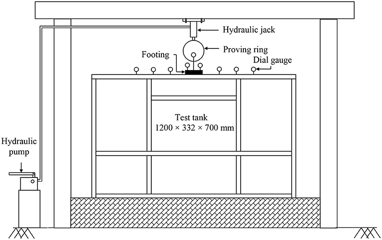
Figure 1. Test setup.
A dry river sand with effective grain size (D10) of 0.22 mm, average grain size (D50) of 0.46 mm, coefficient of uniformity (Cu) of 2.318 and coefficient of curvature (Cc) of 1.03; was used for making the foundation beds. As per the Indian standard specifications (IS: 1498, 1970) the soil was classified as poorly graded sand with letter symbol SP. Its maximum and minimum densities were found to be 17.4 and 14.3 kN/m3, respectively. The soil was placed at a relative density of 70% which was achieved through pluviation technique. Geocells were formed using a biaxial geogrid made of oriented polymer. Aperture size of the geogrid was 35 × 35 mm. Its tensile strength and 5% strain secant modulus as per ASTM StandardD6637 (2009) were 20 and 160 kN/m, respectively. The geocells were formed using geogrid strips interconnected through bodkin joints (Bush et al., 1990), in chevron pattern as shown in Figure 2. The bodkin joints were made of thin plastic strips. The tensile strength of the joint was found to be 3.4 kN/m. Figure 3, shows the geometry of the problem investigated.
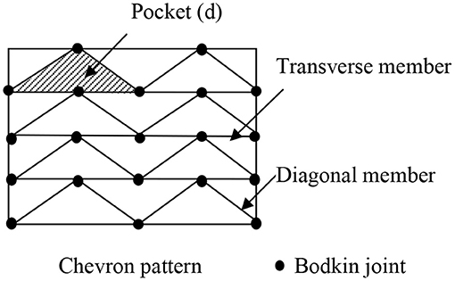
Figure 2. Pattern of formation of geocell mattress.
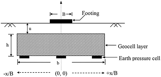
Figure 3. Test geometry.
Through a hydraulic jack, fixed onto the reaction frame, loading was applied in increments. The load installments were maintained on the footing until the settlement stabilized. The settlement magnitudes were recorded through two dial gauges placed on diagonally opposite ends of the footing. Heave and settlement on the soil surface too were measured by dial gauges. The footing was loaded until settlement reached to about 50 mm or bearing failure took place, whichever was earlier.
The vertical contact pressure (σ) on the subgrade soil was measured through strain gauge type earth pressure cells. They were kept under geocell mattress, one below the footing center line and two others at a distance of 1.5B on either side as shown in Figure 3. The pressure cell diaphragms had a radius (R) of 20 mm and thickness (t) of 1.5 mm. They were made of steel having a modulus of elasticity (Ecell) of 2.1 × 10⁵ N/mm2. Modulus of elasticity of the soil (Esoil) was taken as 35 N/mm2. Relative stiffness of the soil-diaphragm wall (Esoil × R3/Ecell × t3) was found to be 0.39. This is a reasonable value for the accuracy of measurement by the pressure cells (Clayton and Bica, 1993). The earth pressure cells were calibrated, by embedding them in sand bed inside a calibration chamber (Dunnicliff, 1988). Relative density of sand in the calibration chamber was same as that in the model tests (i.e., 70%). In unreinforced case, earth pressures were placed at the same depth as in the unreinforced case (i.e., base level of geocell mattress). As suggested by Hadala (1967), the pressure cells were set on the sand bed followed by raining until the test bed was formed. The measured pressures were normalized with respect to the applied footing pressure (q). The normalized pressures (σ/q) depicting the percentage of the footing pressures transmitted to the geocell mattress base are plotted at different footing loads in terms of bearing pressure ratio (BPR), defined as the ratio footing pressure with geocell reinforcement (q) to ultimate bearing pressure (qult) in the unreinforced case.
The model tests were conducted for the geocell mattress width ratios (b/B) of 1, 2, 4, 6, 8, 10, and 12. The pocket size of geocells (d/B), height of geocell mattress (h/B), and depth to the top of the geocell layer below footing (u/B) were kept constant as 1.2, 2.75, and 0.1, respectively. d is the diameter of an equivalent circular area of the geocell pocket opening (Figure 2).
Numerical Modeling
To generate additional data, numerical analysis was carried out using the finite element code, ABAQUS 6.14. A typical model used in the analysis is shown in Figure 4. Using hexahedral eight noded elements (C3D8R) the foundation bed was discretized into 32,640 elements which were found to be adequate for both unreinforced and geocell reinforced models. The geocells were modeled as a continuous sheet, meshed with four noded membrane elements (M3D4R). The minimum number of membrane elements were 866 for geocell mattress of width b/B = 1 and maximum 9,652 for b/B = 12. Vertical boundaries of the foundation bed were constrained in horizontal directions, while its base was constrained both in vertical and horizontal directions.
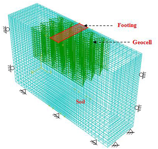
Figure 4. ABAQUS model for geocell reinforced foundation bed.
The soil was modeled as an elastoplastic material obeying Mohr-Coulomb yield criterion with non-associated flow rule. The various material parameters were obtained from the interpretation of the triaxial test data. The geocell was modeled as an elastic material as it was observed that the strains in the geocell generally remained within the elastic range (Leshchinsky and Ling, 2013). As the geocell strength was scaled down during experiments using bodkin joints, the modulus of elasticity was obtained from the strain-strain response of the geocell joint. The geocell was embedded in the foundation bed that the interface friction angle was equivalent to the friction angle of the soil (Satyal et al., 2018). Properties of the foundation soil and geocells used in the analysis are summarized in Table 1.
Table 1. Input parameters used in the finite element model.
After applying geostatic state from the outset, the vertical loading on the footing was simulated imposing equal vertical displacement over the entire width of the footing, in increments of 0.025 mm per load step. The results obtained are presented and discussed in the following section.
Results and Discussions
Typical bearing pressure-settlement responses of the foundation bed, with and without geocell reinforcement, are shown in Figure 5. It is evident that the numerical results are in reasonable agreement with the experimental data. At footing settlement of about 10% of its width, the unreinforced sand has undergone failure. Near vertical slope of the pressure-settlement response and heaving on the soil surface indicates that the failure was largely by shear. In case of geocell reinforcement, no such pronounced failure was noticed. Moreover, the bearing capacity tends to increase significantly.
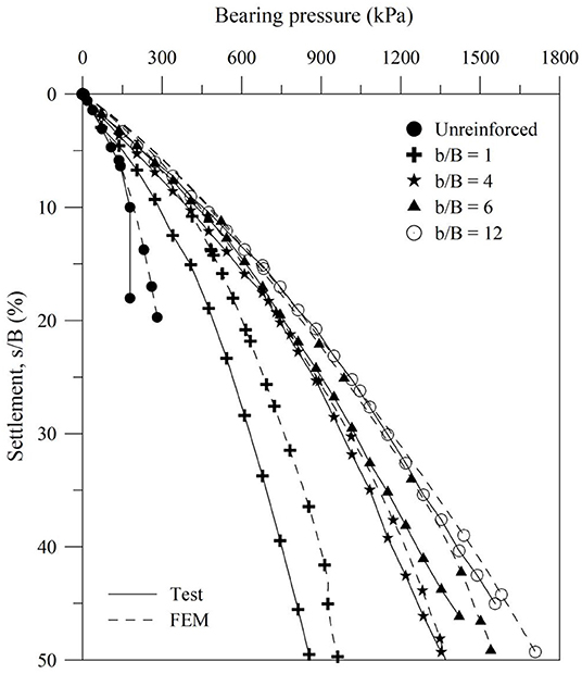
Figure 5. Variation of bearing pressure with footing settlement for different widths of geocell mattress (d/b = 1.2, h/b = 2.75, u/b = 0.1, ID = 70%).
Experimentally obtained typical contact pressure (σ/q) distribution on the subgrade soil underlying geocell mattress is shown in Figure 6. The dotted line depicts the unreinforced case and solid lines depict the reinforced case. In both the cases, the contact pressure is maximum at the center of the footing and appreciably low in the region beyond the loaded region. As the foundation load tends to get dispersed the induced pressure on the soil bed gets reduced toward both the sides of the footing. With geocell reinforcement, the percentage of contact pressure on the subgrade soil tends to reduce significantly. This is because the geocell reinforcement through three-dimensional confinements inhibits shear failure in the soil mass. Indeed, with geocell reinforcement heaving on the soil surface was found to have reduced significantly. The coherent geocell mattress effectively transmits the footing loading to deeper depth leading to reduced pressure on the subgrade soil. At x = 1.5B, the contact pressure responses have almost superposed over each other which indicates that pressure transmitted onto the subgrade soil is proportional to the surcharge pressure on the footing, depicting an elastic behavior. This is because owing to relatively low magnitude of pressure at x = 1.5B, the geocell-soil structure has remained intact and coherent leading to the elastic response.
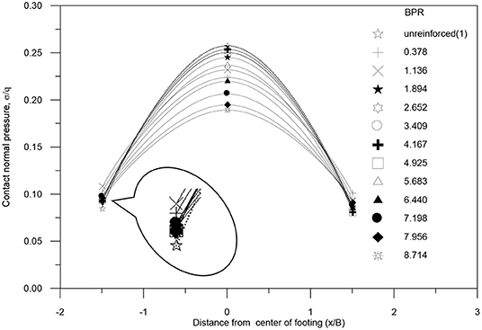
Figure 6. Contact pressure distribution on subgrade soil for b/B = 12 (test data).
Variation of contact pressure with applied footing pressure (BPR) at mid-section of the foundation bed (i.e., along center line of the footing, x/B = 0), for different widths of geocell mattress (b/B), are presented in Figure 7. It can be seen that the percentage of contact pressure transmitted to the subgrade soil initially tends to increase with the increase in footing pressure to reach a peak value. Beyond that, it continues to decrease with increase in footing pressure. Initially the coherent geocell mattress in the foundation bed behaves as a secondary footing that tends to transmit an increased percentage of footing pressure to the subgrade soil, with increase in surcharge loading. At later stage of loading, as the geocell reinforcement tends to get pulled away, significant anchorage resistance is mobilized at both the ends primarily through soil passive resistance over its transverse walls and frictional resistance over the longitudinal walls. As a result of which the geocell reinforcement effectively supports the footing loading leading to reduced pressure on the subgrade soil. Further, it is seen that the contact pressure on the subgrade soil tends to increase with decrease in the geocell width. This is because, with the decrease in the geocell area, the end anchorage reduces. As this anchorage was holding the mattress against bending under footing pressure, with its reduction it deflects more and thereby bringing forth an increase in pressure at the base of the mattress. Moreover, with reduced extent of the geocell mattress, the surcharge load instead of getting redistributed over a wider area tends to get concentrated in the region under the footing leading to an increase in pressure on the underlying soil layer.
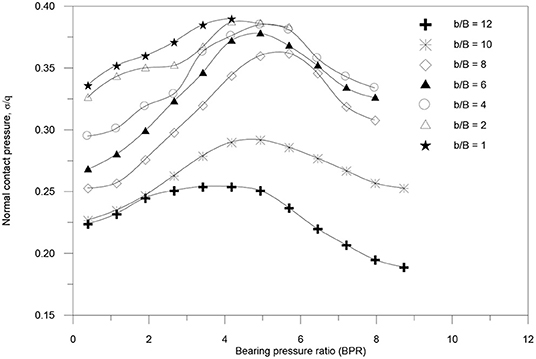
Figure 7. Variation of Contact pressure with bearing pressure at center of footing (0, 0) for different widths of geocell mattress (test data).
Contact normal pressure profile on subgrade soil over the middle half of the foundation bed, obtained from numerical analysis, at 20% footing settlement (s/B) for reinforced and unreinforced cases are depicted in Figure 8. It could be seen that over a distance of about thrice the footing width (x/B = 3) pressure on subgrade soil in the geocell reinforced case is significantly higher than that in the unreinforced case. It indicates that the geocell mattress has effectively transmitted the footing pressure to deeper depths leading to large performance improvement. In contrast, the unreinforced soil has failed in shear and hence could not disperse the footing load over a larger area. It can be seen that beyond a distance (x) of 3B, the difference of contact pressure between unreinforced and geocell reinforced case tends to reduce and beyond x = 5.5B, the difference is significantly less. This is because at a large distance, owing to load dispersion, the footing influence on subgrade soil tends to reduce significantly. Another important point to note is that with increase in the geocell mattress width, contact pressure in the region under the footing tends to reduce. This once again establishes that geocell mattress of larger width mobilizes end anchorage and thereby effectively sustains the footing loading leading to reduced pressure on the subgrade soil.
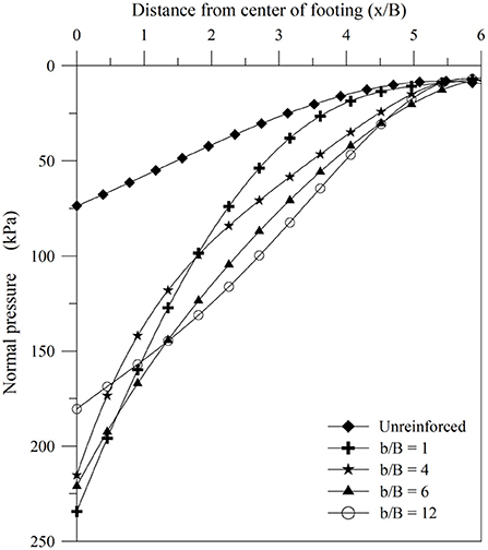
Figure 8. Contact pressure distribution on subgrade soil for different widths of geocell mattress (FEM data, s/B = 20%).
Von Mises stress contours in foundation bed for unreinforced and reinforced cases, at 20% footing settlement, are depicted in Figures 9A,B, respectively. It is shown that with geocell mattress the Von Mises stress in the foundation bed has spread over larger area which indicates that the geocell mattress has transmitted the footing pressure to greater depth in the foundation bed. Correspondingly, the geocell reinforcement is found to have been stressed significantly (Figure 10) which testifies that the geocell reinforcement has actively participated in sharing the footing load leading to increased performance improvement. Vertical stress contours depicted in Figure 11 shows that the geocells in the region under the footing are subjected to compression and beyond are in tension. This indicates that the geocell reinforcement right under the footing directly sustains the footing loading through mobilization of its compressive stiffness and bending rigidity. Whereas, its end portions contribute to performance improvement through mobilization of anchorage which is derived from soil passive resistance and friction.
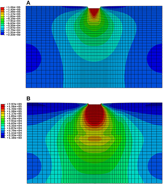
Figure 9. VonMises stress (N/m2) in foundation bed (FEM data, s/B = 20%). (A) Unreinforced. (B) Geocell reinforced.
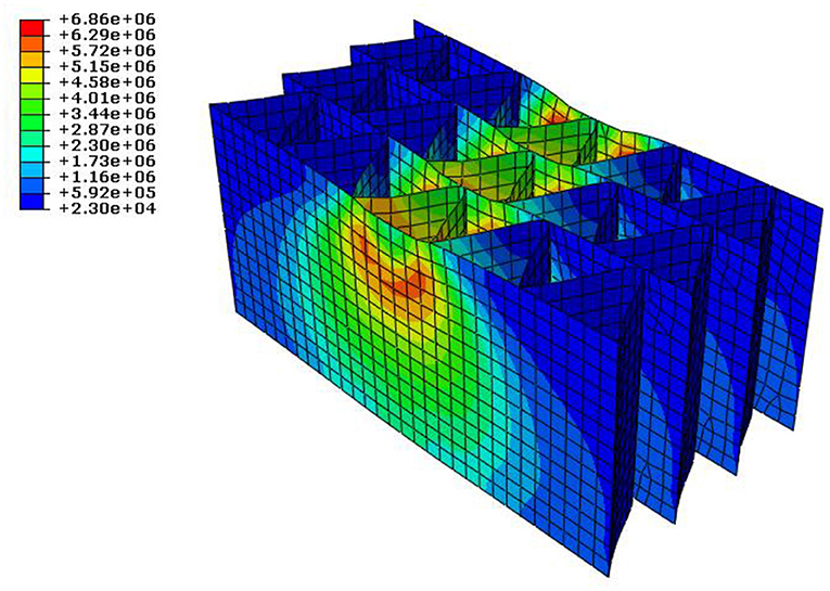
Figure 10. VonMises stress (N/m2) in geocell reinforcement (FEM data, s/B = 20%).
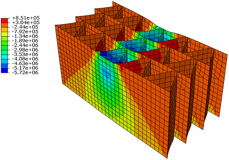
Figure 11. Vertical stress (N/m2) in geocell reinforcement (FEM data, s/B = 20%).
Typical vertical settlement profiles of unreinforced and geocell reinforced foundation beds are shown in Figures 12A,B, respectively. Both are plotted at a constant footing penetration level (s/B) of 20%. It could be seen that with geocell reinforcement the settlement in the foundation bed has distributed over larger area. This is because the geocell reinforcement has effectively confined the soil mass within its pockets forming a semi rigid coherent body that stands against the footing loading and effectively redistributes it leading to settlement over larger area. Indeed, large lateral stress mobilized in the geocell pockets as shown in Figure 13 testifies that geocells have effectively confined the soil mass against shearing under footing loading.
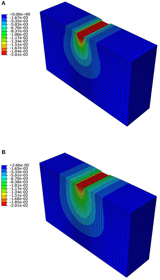
Figure 12. Typical settlement profiles of foundation bed (FEM data, s/B = 20%). (A) Unreinforced. (B) Geocell reinforced.
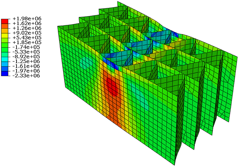
Figure 13. Lateral stress (N/m2) in geocell reinforcement (FEM data, s/B = 20%).
Conclusion
This paper through laboratory model tests and numerical analysis has investigated the influence of geocell reinforcement on the performance of foundation beds. With geocell reinforcement, the contact pressure on subgrade soil reduces significantly. Consequently, the subgrade soil remains undistorted until large loadings. Hence, the bearing capacity of the foundation bed increases significantly. With increase in width of the geocell mattress, the anchorage at both the ends of the geocell reinforcement tends to increase significantly. As a result, it sustains the footing load effectively leading to reduced contact pressure on the subgrade soil giving rise to a significant increase in performance improvement. Von Mises stress contours in the foundation bed indicate that the geocells right under the footing directly sustains the footing loading through mobilization of its compressive stiffness and bending rigidity. Whereas, end portions of the geocell mattress contribute to performance improvement through anchorage derived from soil passive resistance and friction.
Data Availability Statement
The datasets generated for this study are available on request to the corresponding author.
Author Contributions
All authors listed have made a substantial, direct and intellectual contribution to the work, and approved it for publication.
Conflict of Interest
The authors declare that the research was conducted in the absence of any commercial or financial relationships that could be construed as a potential conflict of interest.
Acknowledgments
The authors are thankful to Prof. Ben Leshchinsky, Oregon State University, USA; for kindly sharing the ABAQUS code for the current analysis.
References
ASTM StandardD6637 (2009). Standard Test Method for Determining Tensile Properties of Geogrids by the Single or Multi-Rib Tensile Test Method. West Conshohocken, PA: ASTM International.
Bathurst, R. J., and Jarrett, P. M. (1989). Large scale model tests of geocomposite mattresses over peat subgrades. Transport. Res. Rec. 1188, 28–36.
Bush, D. I., Jenner, C. G., and Bassett, R. H. (1990). The design and construction of geocell foundation mattress supporting embankments over soft ground. Geotext. Geomembranes 9, 83–98. doi: 10.1016/0266-1144(90)90006-X
Clayton, C. R. I., and Bica, A. V. D. (1993). The design of diaphragm-type boundary total cells. Geotechnique 43, 523–535. doi: 10.1680/geot.1993.43.4.523
Dash, S. K., Krishnaswamy, N. R., and Rajagopal, K. (2001). Bearing capacity of strip footings supported on geocell-reinforced sand. Geotext. Geomembranes 19, 235–256. doi: 10.1016/S0266-1144(01)00006-1
Dash, S. K., Rajagopal, K., and Krishnaswamy, N. R. (2007). Behaviour of geocell-reinforcement sand beds under strip loading. Can. Geotech. J. 44, 905–916. doi: 10.1139/t07-035
Dash, S. K., Reddy, P. D., and Raghukanth, S. T. G. (2008). Subgrade modulus of geocell-reinforced sand foundation. Ground Improv. Inst. Civil Eng. London 161, 79–87. doi: 10.1680/grim.2008.161.2.79
Dunnicliff, J. C. (1988). Geotechnical Instrumentation for Monitoring Field Performance. New York, NY: John Wiley.
Emersleben, A., and Meyer, N. (2008). “Bearing capacity improvement of gravel base layers in road constructions using geocells,” in Proceedings of 12th International conference of International Association for Computer Methods and Advances in Geomechanics (Goa: IACMG), 3538–3545.
Hadala, P. F. (1967). “The effect of placement method on the response of soil stress gauges,” in Proceedings of the International Symposium on Wave Propagation and Dynamic Properties of Earth Materials (Albuquerque, NM: The University of New Mexico Press), 255–263.
Hegde, A., and Sitharam, T. G. (2015). 3-Dimensional numerical modelling of geocell reinforced sand beds. Geotext. Geomembranes 43, 171–181. doi: 10.1016/j.geotexmem.2014.11.009
IS: 1498 (1970). Classification and Identification of Soils for General Engineering Purposes. Bureau of Indian Standards.
Leshchinsky, B., and Ling, H. I. (2013). Numerical modeling of behavior of railway ballasted structure with geocell confinement. Geotext. Geomembranes 36, 33–43. doi: 10.1016/j.geotexmem.2012.10.006
Mitchell, J. K., Kao, T. C., and Kavazanjiam, E. Jr. (1979). Analysis of Grid Cell Reinforced Pavement Bases. Technical Report No. GL-79-8, U.S. Army Waterways Experiment Station.
Rea, C., and Mitchell, J. K. (1978). “Sand reinforcement using paper grid cells,” in ASCE Spring Convention and Exhibit, Preprint 3130 (Pittsburgh, PA).
Keywords: soil, geocell reinforcement, strip loading, contact pressure, finite elements
Citation: Dash SK, Saikia R and Nimbalkar S (2019) Contact Pressure Distribution on Subgrade Soil Underlying Geocell Reinforced Foundation Beds. Front. Built Environ. 5:137. doi: 10.3389/fbuil.2019.00137
Received: 28 August 2019; Accepted: 04 November 2019;
Published: 19 November 2019.
Edited by:
Eduardo Cabrita Fortunato, National Laboratory for Civil Engineering, PortugalReviewed by:
Chayut Ngamkhanong, University of Birmingham, United KingdomPing Liu, Jiangsu University of Science and Technology, China
Amarnath M. Hegde, Indian Institute of Technology Patna, India
Copyright © 2019 Dash, Saikia and Nimbalkar. This is an open-access article distributed under the terms of the Creative Commons Attribution License (CC BY). The use, distribution or reproduction in other forums is permitted, provided the original author(s) and the copyright owner(s) are credited and that the original publication in this journal is cited, in accordance with accepted academic practice. No use, distribution or reproduction is permitted which does not comply with these terms.
*Correspondence: Sujit Kumar Dash, c3VqaXRAY2l2aWwuaWl0a2dwLmFjLmlu