 Luciano Ombres
 Salvatore Verre
- Departement of Civil Engineering, University of Calabria, Arcavacata di Rende, Italy
The Fabric Reinforced Cementitious Matrices (FRCMs) and Steel Reinforced Grout (SRG) are a promising strengthening solution for existing masonry since inorganic matrix is considerably compatible with historical substrates. The present paper is focused on a Finite Element (FE) analysis of masonry columns confined with FRCM composites developed by Abaqus-code. The masonry columns were modeled using a macro model approach. The model was performed by using the following functions Concrete Damage Plasticity (CDP) and the Plastic (P) in order to describe the constitutive laws of material for masonry columns and external reinforcement, respectively. Typical failures of FRCM-systems are slippage of the fibers within the embedding matrix, instead for SRG-systems are detachment of the composite strip at the fabric-matrix interface and fiber rupture. In addition, perfect bond was considered for the interaction between the masonry column and in the overlap zone the bond slip law was modeled on the base of the failure mode. Results of an experimental investigation on FRCM and SRG clay brick masonry columns are used to calibrate the numerical model.
Introduction
Fabric Reinforced Cementitious Matrix (FRCM) consisting of fibers such as carbon, PBO (short of polyparaphenylenebenzobisoxazole), glass or basalt in form of bidirectional fabric with inorganic matrix and, Steel Reinforced Grout (SRG) consisting of continuous unidirectional steel fibers with inorganic matrix are recently, largely employed for strengthening or retrofitting of existing reinforced concrete and masonry structures. Both composite systems have high resistance to fire, elevated temperature and UV radiation; they are compatible with the concrete or masonry substrate and have unvarying workability temperature (between 4 and 40°C) (Nanni, 2012). Results of recent studies and research give evidence of the flexural and shear capacity increase of FRCM/ SRG strengthened masonry (Papanicolaou et al., 2007, 2008; Babaeidarabad et al., 2014; de Felice et al., 2014; Mezrea et al., 2016; Santandrea et al., 2017b) and concrete structures (Ombres, 2011, 2014, 2015a; D'Ambrisi and Focacci, 2012; Loreto et al., 2014; Carloni et al., 2016; Sneed et al., 2016; Tetta et al., 2016; Thermou et al., 2016; Ombres and Verre, 2018a, 2019). The performances of masonry columns confined with FRCM/SRG have also been analyzed by experimental investigations (Carloni et al., 2015; Ombres, 2015b; Cascardi et al., 2017, 2018a,b; Fossetti and Minafò, 2017; Maddaloni et al., 2017; Santandrea et al., 2017a; Sneed et al., 2017; Minafò and La Mendola, 2018; Minafò et al., 2018); obtained results evidenced the effectiveness of the confining systems with an increase both in axial load capacity and ductility. Carbon FRCM-confined clay brick columns subjected to eccentric load have been tested by Ombres (2015b); obtained results highlight the increase of both strength and transversal displacements with increasing the confinement ratio (i.e., the number of confining layers). Fossetti and Minafò (2017) tested masonry columns confined with basalt-FRCM jackets and steel wires embedded into the mortar joints. Main results of tests evidenced an enhancement of both the ultimate strain and the absorbed energy of columns confined with steel wires. The use of basalt-FRCM jackets was effective in enhancing the strength only for low grade masonry columns; for normal strength masonry columns they are effective in increasing the energy absorption but they have a limited effect on the increase of the axial capacity. Sneed et al. (2017) tested clay masonry columns confined with one SRG layer. Parameters varied were the density of the steel fibers and the value of the columns corner radius. Columns were tested under axial compression load. Main results of the investigation evidenced that (i) with respect to unconfined columns, the SRG jacketing increased the compressive strength of the columns by 27–41%, (ii) the compressive strength of the SRG confined columns increases with both corner radius ratio and fiber density. Full-scale masonry columns built with limestone blocks and hydraulic mortar, confined with glass-FRCM and basalt-FRCM jackets have been tested by Maddaloni et al. (2017). Results of tests demonstrated a significant increase of both strength and ductility in confined column with respect to unconfined ones. Mezrea et al. (2016) tested historical masonry pier columns confined with open grid basalt-reinforced mortar. Experiments showed that confined columns provided a small compressive strength gain with respect to the unconfined ones. Basalt and steel-FRCM confined masonry columns with a square cross-section were tested under monotonic axial compression load also by Santandrea et al. (2017a). Both confining systems provided an increase of the average compressive strength with respect to un-confined specimens: the increase was equal to 14%−16% for basalt fibers and 33% for steel fibers. The lower performances of basalt fibers were attributed to the brittle nature and the relatively low tensile strength of the basalt fibers that tend to rupture near the corners of the columns. Brick masonry columns confined with one layer of PBO-FRCM were tested by Carloni et al. (2015). In order to investigate the influence of different brick configurations on the behavior of confined columns, full-scale and scaled bricks were used to build columns. The role of the mortar joints and the arch effect across the section of the columns due to the confinement were also investigated. An experimental and numerical investigation on clay brick masonry columns confined with SRG have been recently developed by the Authors (Ombres and Verre, 2018b). Confined columns were tested under axial and eccentric load until collapse varying the number of confining layers, the confining configuration and the load eccentricity. Obtained results evidenced that for axially loaded columns, strength, and ductility values are increasing with the confinement ratio while they are decreasing with the increase of the load eccentricity.
Cascardi et al. (2018a), investigated the role of the inorganic matrix on the effectiveness of FRCM confined masonry columns. Three different inorganic matrices were used for confining poor quality masonry columns tested under axial load. A significant improvement of the mechanical properties of the FRCM confined masonry columns when a proper grade of mortar matrix is used was confirmed by experimental results. Even if significant, experimental results are limited and they do not allow defining appropriate models to predict the structural response of FRCM/SRG confined masonry columns. Actually only few models proposed through the analysis of experimental results were available (Krevaikas and Triantafillou, 2005; Di Ludovico et al., 2010; Cascardi et al., 2017, 2018b; Fossetti and Minafò, 2017). A designed-oriented model (DOM) based on a multiple linear regression approach in which the independent variables depend on the strength of the mortar and the elastic modulus of the fibers, was proposed by Cascardi et al. (2017, 2018b). A simplified version of the model which was found to be in good agreement with the DOM was also proposed by the same authors. Semi-empirical models similar to those defined for FRP-confined masonry, modified including coefficients calibrated through experimental results was proposed by Krevaikas and Triantafillou (2005), Di Ludovico et al. (2010), and Fossetti and Minafò (2017). Many variables such as the types of masonry and FRCM/SRG systems, the fiber confinement ratio, the type of mortar, the confining configuration, the geometry of the columns influence the predictions of the models; as a consequence, they cannot be able to furnish reliable predictions of all types of FRCM/SRG-confined masonry elements. To overcome these difficulties, computer simulations are a valid alternative to analyze the performances of FRCM/SRG confined masonry columns in a time-saving way. Numerical procedures could be, then, more effective than analytical or semi-empirical models in predicting the structural responses of FRCM confined masonry columns. At this aim, in this study, a numerical procedure found based on a Finite Element (FE) analysis of masonry columns confined with FRCM/SRG composites, developed by the ABAQUS (2014), is proposed. The masonry columns were modeled by a macro model approach. The model was performed by using the Concrete Damage Plasticity (CDP) and the Plastic (P) functions to describe the constitutive laws of material for masonry columns and external reinforcement, respectively. Mechanical parameters were calibrated by experimental results; in addition, perfect bond was considered for the interaction between the masonry column while in the overlap zone a non-linear bond-slip law, modeled on the base of the failure mode, was adopted. Results of an experimental investigation conducted on small-scale clay brick masonry columns confined with different FRCM systems (namely Steel-FRCM or Steel Reinforced Grout, SRG, PBO-FRCM and basalt-FRCM) and subjected to compressive axial load, were reported and used to calibrate the numerical procedure. The comparison between experimental results and numerical predictions in terms of both ultimate strength, axial stress-strains response, allows evidencing the effectiveness of the proposed numerical procedure.
The Numerical Procedure
The numerical procedure developed by the Finite Element Software package ABAQUS Finite Element Code is described in the following sections.
Geometrical Modeling
Confined masonry columns were modeled in three-dimension (3D). In particular, for both the masonry column and the external reinforcement a macro model approach was used. The macro model approach, based on the same approach used in reinforced concrete structures, has been used in the analysis of masonry structures as reported in the technical literature; moreover, this strategy was adopted for un-strengthened column in order to properly replicate new masonry structures (Verre et al., 2019) or analyze the behavior of existing historical structures (Fortunato et al., 2017 and Olivito and Porzio, 2019). This technique does not allow to distinguish the single brick and the mortar joint (vertical or horizontal). It allows to describe the masonry as a homogenous material and in the meantime it significantly reduces the computational burden. The element used to model the masonry columns is the linear tetrahedral four node C3D4 element with constant stress. In Figure 1 the geometrical representation of the proposed FE-model is shown; in particular, Figure 1A illustrates the mesh for the unconfined column composed of 248,681 elements, while in Figure 1B is represented the mesh relative at the external reinforcement with the round corner inclusive using 9,060 elements.
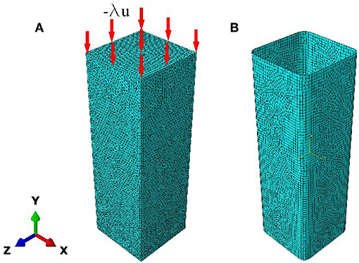
Figure 1. Geometrical representation of the FE model: (A) masonry substrate for unconfined column and (B) external reinforcement.
The external reinforcement was modeled by a S4 shell element. Generally, this element is used to model mono-dimensional structures and the thickness is significantly smaller. This element describes the geometry of the external reinforcement such as a continuous and homogenous surface. Moreover, this element allows transverse shear deformation. In addition, the shell element uses the thick shell theory as the shell thickness increases and becomes discrete Kirchhoff thin shell element as the thickness decreases; the transverse shear deformation becomes very small as the shell thickness decreases.
Materials Model
The two macro elements used to compose the numerical model was described by different functions. In order to predict the constitutive behavior of masonry columns, a function called Concrete Damage Plasticity (CDP) was used. This particular function has a good capacity to model the quasi-brittle materials present in whatever structure. Moreover, the CDP model is an extended Drucker–Prager model, in particular, it presents a modification at yield criterion. A parameter k was added in order to account the effect of the third deviatoric stress invariant.
The yield criterion adopted has the following form:
where θ and k are parameters to be determined, I1 is the first deviatoric stress invariant, while s has the following form:
being J2 and J3 the second and third deviatoric stress invariant, respectively. Using Equation (2) the shape is no longer circular in the deviatoric plane. However, the value of k is restricted between the values 0.778 and 1.0, so that it ensures the convexity at yield surface. Moreover, parameter k is not influenced by the concrete under triaxial compression results. In addition, in the CDP model it is possible to define the strain hardening/softening function as a potential function parameter that may be the same as or different from the frictional parameter to allow either the associated or the non-associated flow rule to be used. In Figure 2 the failure surface in the deviatoric plane, as reported in Teng et al. (2010), is reported.
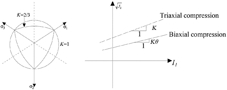
Figure 2. Failure surface of the CDP Model.
More parameters present in the CDP model are the following:
• dilation angle (DA): angle measured in the meridional plane between the failure surface and the hydrostatic axis.
• plastic potential eccentricity (PPE): length's segment evaluated in the hydrostatic axis between the vertex of the hyperbola and the intersection of the asymptotes with respect to the center of the hyperbola.
• Fbo/fco: ratio between the initial biaxial compressive yield stress, Fbo, and the initial uniaxial compressive yield stress, fco. This ratio was obtained from experimental results.
• viscosity parameter (VP): used for the visco-plastic regularization of the concrete constitutive laws.
The model's parameters used in the numerical procedure are: DA = 38°, PPE = 0.10, Fbo/fco = 1.16 and VP = 0.0.
The constitutive compressive law of the masonry was modeled by the non-linear relationship proposed by Vecchio and Collins (1986), where fcm and εc are the maximum compressive stress and strain in correspondence of the maximum compressive stress, respectively (Figure 3). The constitutive tensile law was modeled the following bilinear function
where ft and εt are the tensile stress and strain in correspondence of the maximum tensile stress, Et is the tensile modulus and μ is a factor controlling the rate of tensile strength decay present only in the second branch.
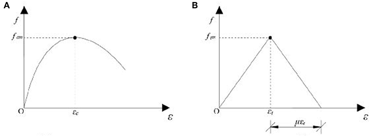
Figure 3. Material constitutive laws: (A) compression and (B) tension.
The external reinforcement was modeled by the Plasticity function (P). In particular, P defines the behavior with a series of straight lines joining the given data points. The first piece of data given defines the initial peak stress of the material and, therefore, should have a plastic strain value of zero.
The strains provided in material test data used to define the plastic behavior must be plastic strain obtained by subtracting the elastic strain.
Solution Technique
The common static solution strategies such as arc-length method, Crack Opening Displacement (COD) control method, Cracking Mouth Sliding Displacement (CMSD) control method, the arc-length method, and the crack length control scheme, have been attempted with some success, but such methods have been reported to have difficulties in finding a convergent solution. In particular, the arc length has a problem due to snap-back or snap-through phenomena. Several dynamic solution methods have been employed to analyze various static problems in structural mechanics. In modeling structures made of brittle materials such as concrete and masonry, unstable structural responses due to crack propagation strain-softening usually exist and may induce a problem on the convergence of the solution (Fabbrocino et al., 2019). Some studies present in the literature have attempted to use the dynamic solution methods to analyze various static problems in structural mechanics. In particular, the explicit FE method to solve the above-mentioned problem was adopted by Chen et al. (2015) and Ombres and Verre (2019).
Dynamic Solution
The dynamics procedure used in this study is typically used to solve the problems about the quasi-static simulations involving complex non-linear effects such as problems that involve complex contact conditions. Many of the advantages of the explicit procedure apply to slower (quasi-static) processes. Equation of motion about the dynamic structural problem can be expressed as:
where M, C, and K are the mass, damping, and stiffness matrix, respectively; F is the applied force vector; , ḋ, and d, are acceleration, velocity, and displacement vectors, respectively. In a dynamic solution the direct integration on the equation of motion by central difference operator was used, in particular, the Hilber-Hughes-Taylor (HHT) operator on time integration for the quasi-static application was used. Moreover, the HHT operator is an extension of the Newmark β -method.
The equation is usually solved using the following finite difference formulae:
where an, υn, and dn are, respectively the acceleration, velocity and displacement vectors at time step n, Δt is the time increment, and α, β, and γ are the constants of the time integration algorithm. The default values present in Abaqus are: α = −0.05; β = 0.28, and γ = 0.55. The “variable mass scaling” function was used in this numerical model, in order to scale the mass of elements at the beginning of a step and periodically during that step. The mass scaling factor is equal to 0.00005. The discrete mass matrix used in the equilibrium equations plays a crucial role in both computational efficiency and accuracy problems. Mass scaling for quasi-static analysis is performed on the entire model. However, this numerical model is composed of different parts. The parts have different stiffness and mass properties, therefore, each of the parts were scaled independently. Finally, the last important parameter for the applicability of the dynamic approach in predicting static structural response and its ability in overcoming convergence difficulties associated to cracking and interfacial debonding is the ratio of the kinetic energy to the total energy must be significantly smaller than 5% during the whole process (except at the beginning of the load application) which ensures the predicted response that is basically the static response.
Boundary Condition and Interface Modeling
The numerical test was conducted in displacement control -λu. The displacement was applied at the top of the columns by linear type amplitude curve. At the base of the columns the vertical and horizontal displacement and the rotation were blocked. The type of the interaction between the external reinforcement and the masonry substrate is reported in Figure 4. The perfect bond was applied on all sides of the column, but particular attention was focused at the overlap zone.
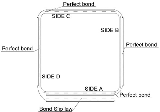
Figure 4. Scheme of interaction between the external reinforcement and masonry columns substrate.
On the basis of the failure mode showed and discussed in section Failure mode and present in the literature (Santandrea et al., 2017b; Sneed et al., 2017) the interaction between the first layer and the overlap layer was modeled by a bond slip law. The different interaction between the masonry substrate and the external reinforcement is reported in Figure 4. The interaction between the first layer and the overlap layer was used as an interface cohesive surface. The bond slip law adopted is reported in Lu et al. (2005), and it is a bilinear model. The bond slip curve was developed for FRP systems, but in recent studies (Ombres and Verre, 2019; Verre et al., 2019) that involved this bond slip law, it also obtained good results for elements strengthening with the FRCM/SRG systems. In addition, the bond slip law was evaluated by statistic studies and a meso-scale finite element model on a large database on the single-lap direct shear test. The last one was used in order to evaluate the initial stiffness of bond slip curve. This bilinear model, illustrated in Figure 5 is described by the following equations:
where
Moreover, the parameter τfwas calculated as follows:
being bf and bc widths of the SRG/FRCM strip and the cross-section, respectively, while fmaxt is the maximum tensile stress obtained in the single lap direct shear tests, which in this case was set as average values on the results present in literature for steel, basalt, and PBO fibers (Carloni et al., 2017; Santandrea et al., 2017a; Ombres et al., 2019). Particular attention was focused on the γ parameter evaluated. The value of the γ parameter with respect to the values (1.5) present in Lu et al. (2005), in this work was estimated by statistical and FE analysis by Abaqus, and is equal to 0.75 for the SRG system, 0.55 for the PBO-FRCM and 1.0 in the case of the basalt-FRCM. Moreover, the parameter Gf (interfacial fracture energy) was calculated as:
and it is equal to the area of the bond slip law function of the parameters evaluated with the equations 12,13, and 14. Finally, the k0 is the initial stiffness for the bond slip law reported in Figure 9. To evaluate k0 many experimental results are needed; due to the limited available test results relative to the considered confining systems, the value of k0 was assumed unchanging with respect to that one reported in Lu et al. (2005). The values of k0 (N/mm3), τf (N/mm2), and Gf (N/mm) are reported in Table 1. The function to describe the interaction at the overlap zone is the “traction separation approach”. It was used to describe the relative displacement for each point of contact, moreover, it was considered as a bi-linear type with a linear elastic behavior followed by a softening branch that describes the evolution of the damage.
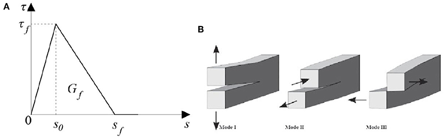
Figure 5. Interface modeling: (A) bond slip law and (B) mode I, mode II, and mode III.
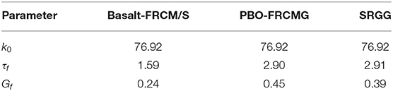
Table 1. Lu's parameters values.
The model is characterized by three failure modes: the opening (Mode I) associated with the normal stress, and the sliding (Mode II and Mode III) associated with shear stress, reported in Figure 5.
The initialization of the damage is evaluated through a quadratic function, defined as: and it is equal to
where σ, τs, and τt are the normal (mode I) and shear (modes II, III) stresses at the interface, respectively. The stresses σmax and τmax are the maximum stresses in normal and shear directions, respectively. The evolution of the damage is, instead, described as concerns fracture energy as shown in Equation 18. The power law fracture criterion was adopted to express the connection between the fracture energy and the mixed mode. It states that under mixed-mode conditions the failure is governed by a power law interaction of the energy required to cause failure in the individual modes, given by:
In Equation 18, Gn, Gs, and Gt, are the work of the interface stresses for the relative displacements. In the present work = = Gf, while σmax was set equal to the tensile strength of the matrix fmt and the corresponding was assumed equal to 10% of Gf. In addition, value α = 2 was used (Carloni et al., 2018).
Experimental Investigation
Six small scale columns were tested under axial concentric load. The columns have a quadratic cross section and height equal to 250 and 770 mm, respectively. In addition, masonry columns at the corner were rounded with a radius equal to 20 mm. Moreover, each column, at the top and at the bottom was capped with a 40 mm thick layer of high strength mortar. The geometry of the masonry column was reported in Figure 6.
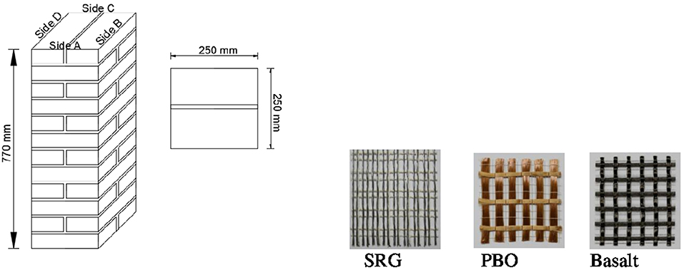
Figure 6. Geometry of the masonry columns and FRCM textiles.
Two columns were unconfined and used as control specimen, while the other four columns were confined with two different strengthening systems FRCM and SRG. In particular, the FRCM system was used with two different types of fibers PBO and Basalt, while the steel fiber was adopted in the SRG system. The types of fibers were reported in Figure 6. The columns were strengthened with one reinforced layer and the same overlap length for all strengthened systems was equal to the width of the masonry column.
The following experimental investigation, refers to PBO-FRCM and basalt-FRCM; the behavior of SRG confined columns was reported and discussed in a previous paper (Ombres and Verre, 2018b). Confined masonry columns were named according to the following designation: C-X-Z, where C indicates the confined specimen, X indicates the type of fiber, and Z indicates the specimen number. Un-strengthened masonry columns were named according to the following designation: USC. Table 2 reports details of the tested columns. In addition, column C-S-2 with respect to column C-S-1 has a different local position of the overlap layer.
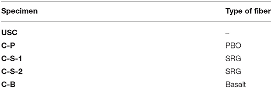
Table 2. Geometrical details of tested specimens.
Materials
The masonry column was assembled by a single brick unit with nominal dimensions of 250 × 120 × 55 mm and a low strength mortar. Moreover, mechanical properties of bricks were determined by standard compression tests on 5 bricks performed according to the UNI EN 772-1 (2015), while for the low strength mortar the compressive and flexural tensile strength was determined by standard tests according to UNI EN 12190 (2000) and UNI-E 1015-11 (2016). In addition, at the top and at the base of the columns was applied a high strength mortar in order to assure a uniform pressure and to guarantee also the setting of the columns in plane and parallel. The compressive strength of the brick units was 56.84 N/mm2 (C.o.V. = 0.02) while the compressive strength and the flexural tensile strength values were 3.32 N/mm2 (C.o.V. = 0.07) and 1.22 N/mm2 (C.o.V. = 0.04), respectively, for the low strength mortar and 59.4 N/mm2 (C.o.V. = 0.017) and 5.61 N/mm2 (C.o.V. = 0.08), respectively, for the high strength mortar (Ombres and Verre, 2018b). The small-scale columns were confined with three different reinforced systems: SRG, basalt-FRCM and PBO-FRCM. The SRG and basalt-FRCM system consisted of a steel sheet and basalt fabric mesh embedded in a mineral-NHL mortar. The steel sheet used, has the surface density equal to 1,200 g/m2 and it is composed of the galvanized micro-cords. Moreover, each micro-cord has a cross sectional equal to 0.538 mm2. The basalt fabric mesh consists of a balanced, coated bidirectional fabric and stainless steel micro-wires. The surface density of basalt fiber is equal to 400 g/m2 and the space between the single yarn is equal to 8 mm in both directions. Instead the matrix used with the PBO fiber net is a type of pozzolana mortar. The PBO (polyparaphenylenebenzobisoxazole) fabric mesh develops in two orthogonal directions, in particular, the principal direction (longitudinal) has the equivalent thickness t* equal to 0.046 mm, while in the perpendicular direction (transversal bundle) it is 0.012 mm. The average values of the compressive strength and the flexural tensile strength for the mineral-NHL mortar were 12.85 N/mm2 (C.o.V. = 0.15) and 2.65 N/mm2 (C.o.V. = 0.05), respectively, and 36.16 N/mm2 (C.o.V. = 0.04) and 5.50 N/mm2 (C.o.V. = 0.014), respectively, for the pozzolana mortar.
Specimens Preparation
The confined columns were wetted before installing the composite jacket. It is possible to divide the application of the strengthening system in three parts. Firstly (or first step), the internal mortar was applied to the columns; then (second step), a single layer of sheet/fabric mesh was disposed within the internal mortar layer, pushing carefully to control an appropriate impregnation and then wrapped around the column. Finally (third step), the external mortar layer was applied. The thickness of the mortar layer was assumed equal to 3 mm as recommended by the manufacturer's instructions.
The width of the PBO and basalt fabrics was higher than the height of the columns and, consequently, only one fabric segment was used for each confining layer, while the width of the commercial steel fiber fabric was 300 mm and, then, it was less than the length of the columns. Therefore, for each single steel layer, the specimens were strengthened with three segments that butted up against each other along the column length. In particular, the three steps used to strengthen the masonry column are reported in Figure 7. A particular attention was given at the local position of the overlap. For all specimens the overlap zone was on side A (see Figure 4). Moreover, for only specimen C-S-1, the position of the overlap zone along the height of the columns was defined in a way that it does not form a vertical seam near the column corner. In particular, the overlap zones were on side A and C. Since the steel fiber sheet is wide equal to 300 mm, it was cut and bent with a height equal to 256 mm in order to strengthen the column with three segments throughout the entire height, as it is possible to see in Figure 7B. The first and third segment were overlapped on side A, instead the second (middle) segment on side C. Furthermore, for column C-S-2 the overlap zone for the three segments was side A. After casting, the masonry columns were cured in laboratory under wet clothes for 28 days prior to testing.
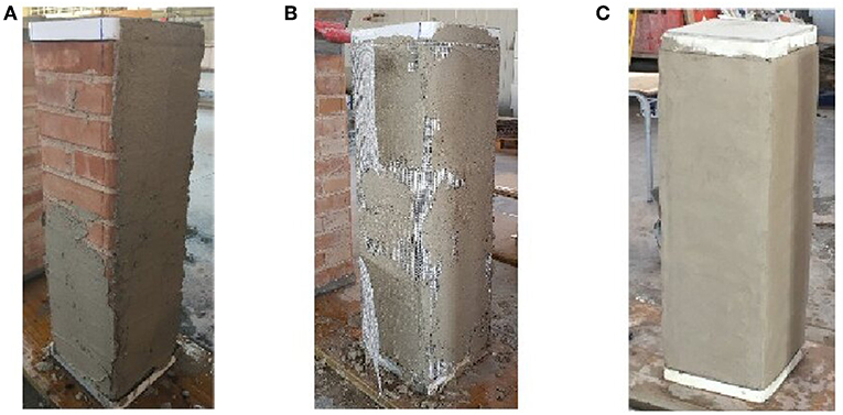
Figure 7. Steps to confine columns with one layer of composite material: (A) installing the internal mortar layer, (B) installing the sheet/fabric mesh, and (C) installing the external mortar layer.
Test Setup
The load was applied at the top of the columns by a system composed of two elements: a steel top plate with a knife-edge and an adaptor steel plate. Both plates have a thickness of 20 mm. The plate and the adaptor were modeled to receive the center/eccentric load. A similar system was applied at the bottom of the specimen. The test was conducted through machine stroke control with a load rate of approximately 40 N/s, and it was ended when a significant drop appeared in load after the peak load response. The vertical and lateral displacement was measured by four and twelve linear variable displacement transducers (LVDTs), respectively (Figure 8). The vertical LVDTs were placed at the corners of the small-scale columns. The twelve LVDTs were positioned along the height of the columns; three LVDTs for each face of the column, in particular at the top, at the mid height and at the bottom.
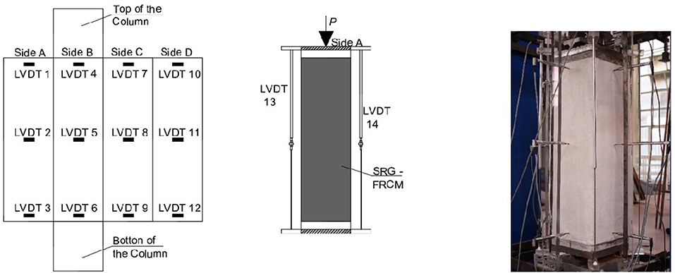
Figure 8. Test set up.
Results of Tests
Failure Mode
Different failure modes were observed: for the un-confined masonry columns; the type of failure showed was brittle and it was due to the crushing of the masonry. The failure configuration is characterized by the presence of a vertical crack, formed during tests at the middle of the specimens. The failure modes of confined specimens were different for the various types of confining systems adopted. The columns strengthened with basalt fibers showed a type of failure associated to the detachment of the external matrix layer as observed in a previous work (Santandrea et al., 2017a; Sneed et al., 2017) and a rupture of the basalt grid. While in the PBO strengthened column a very wide vertical crack, formed in correspondence of two corners of the columns causing the rupture of the PBO fibers and the masonry column, was observed. Instead, for the columns strengthened with steel fibers a detachment of the steel segments in correspondence of the overlap zones was observed. All types of failures are summarized in Figure 9.
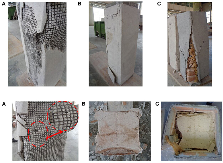
Figure 9. Failure configurations for confined columns with: (A) Basalt-FRCM, (B) SRG (C-S-2), and (C) PBO-FRCM.
Load-Strain Curves and Peak Load
Figure 10 shows the stress-strain curves for each type of strengthening system investigated.
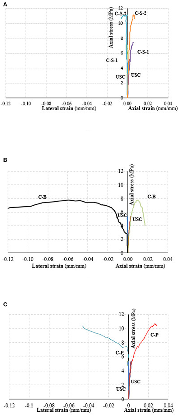
Figure 10. Axial stress-strain curves of confined columns: (A) SRG, (B) Basalt-FRCM, and (C) PBO-FRCM.
Table 3 reports values of the peak load recorded during the tests for all specimens. It is interesting to note the influence of the overlap configuration on the peak load value. The comparison of values corresponding to C-S-1 and C-S-2 specimens, both confined with one SRG layer, evidences, in fact, that the peak load of the C-S-2 specimen was 42% higher than that of the C-S-1 specimen.
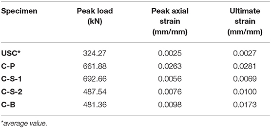
Table 3. Test results.
Numerical—Experimental Comparison
The implemented numerical procedure was adopted to perform a numerical analysis of FRCM/SRG -strengthened masonry columns. Results of the are described in the following.
Un-confined Specimen
Figure 11 reports experimental and numerical curves for the un-confined specimen USC. By observing the comparison, it is possible to note that the numerical procedure provides a good forecasting of the unconfined columns behavior. The predicted value of the peak axial stress, 5.77 MPa, is slightly higher than the experimental one, 5.18 MPa. In elastic range the numerical curve increases, even if only slightly, in terms of stiffness, while its softening branch has a sudden and rapid degradation of the axial stress. Probably this is due to the adopted compressive constitutive law of the masonry.
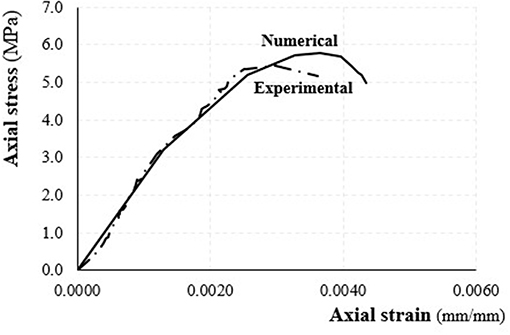
Figure 11. Un-confined columns: experimental vs. numerical axial stress-axial strain diagrams.
Confined Specimen
Figure 12 shows the comparison between the numerical/experimental curves for masonry columns confined with basalt-FRCM (C-B) and SRG (C-S-1 and C-S-2).
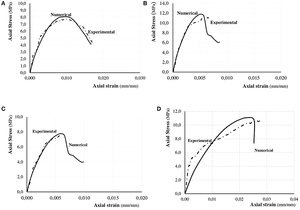
Figure 12. Experimental vs. numerical axial load-axial strain diagrams: (A) C-B, (B) C-S-1, (C) C-S-2, and (D) C-P.
By analyzing Figure 12, it appears as for the C-B column the numerical prediction is in very good agreement with experimental results both in ascending and descending branches. The peak stress was well-predicted: only a small difference between the predicted value (8.04 MPa) and the experimental one (7.75 MPa) was obtained.
The numerical curves relative to SRG confined columns provided a good prediction in terms of axial peak stress and axial strain at the peak stress. The peak axial stress reached by the numerical curve slightly increases with respect to the experimental curves. In particular, for the C-S-1 column the predicted peak stress was 11.79 MPa, while the experimental one was 11.14 MPa. For the C-S-1 column the predicted value was 7.77 MPa while that experimental was 7.57 MPa.
In terms of the axial strain at the axial peak stress the numerical value predicted for the C-S-1 column, equal to 0.00512 mm/mm was smaller than experimental value, while a good correlation was obtained between predicted and experimental values for the C-S-2 column. For both SRG confined columns, the numerical procedure is unable to well describe the descending branch of the curve. This is due to the different failure mode showed during the test and type of model used in order to describe the boundary condition of the column strengthened with PBO.
For PBO-FRCM confined column, the numerical predictions are very different from those experimental both in ascending and descending branch. The peak stress value is, also, overestimated by numerical predictions.
Conclusions
A numerical procedure found based on the Finite Element developed by the Abaqus-code is described in this paper. Parameters of the numerical model were calibrated on available experimental results. The effectiveness of the model was evaluated by a comparison with results of tests conducted on clay brick masonry columns confined with FRCM (basalt-FRCM and PBO-FRCM) and SRG confining systems.
Based on results obtained in this investigation, the following concluding remarks can be drawn:
• the proposed numerical procedure furnishes accurate outcomes in term of axial strength both for unconfined and confined masonry columns;
• for basalt-FRCM and SRG confined columns, numerical predictions in terms of axial stress-axial strain curves are in good agreement with experimental results in the ascending branches of curves while they are un-accurate to describe the post-peak behavior of columns mainly in the case of SRG confined columns;
• the experimental behavior of the PBO-FRCM confined masonry column is not well predicted by the numerical model.
Further studies are necessary to simulate the phenomenon both of the unconfined columns (using other constitutive laws available in literature) and of the confinement with FRCM systems in terms of type of numerical model. Further experimental analysis, are needed to confirm the results obtained in the investigation described and discussed in the paper; experimental results are, also, essential for better calibration of parameters of the prediction model examined in this study.
Data Availability Statement
The datasets generated for this study are available on request to the corresponding author.
Author Contributions
LO and SV contributed equally to the conception or design of the work and the acquisition, analysis, and interpretation of data for the work. LO and SV drafted the work revising it critically for important intellectual content, provided approval for publication of the content, and agreed to be accountable for all aspects of the work in ensuring that questions related to the accuracy or integrity of any part of the work are appropriately investigated and resolved.
Conflict of Interest
The authors declare that the research was conducted in the absence of any commercial or financial relationships that could be construed as a potential conflict of interest.
References
Babaeidarabad, S., Arboleda, D., Loreto, G., and Nanni, A. (2014). Shear strengthening of unreinforced concrete masonry walls with fabric reinforced cementitious matrix. Constr. Build. Mater. 65, 243–253. doi: 10.1016/j.conbuildmat.2014.04.116
Carloni, C., Bournas, D. A., Carozzi, G., D'Antino, T., Fava, G., Focacci, F., et al. (2016). “Fiber reinforced composites with cement (inorganic) matrix,” in Design Procedures for the Use of Composites in Strengthening of Reinforced Concrete: Rilem State-Of-The-Art Reports 19, eds C. Pellegrino, and J. Sena-Cruz (Berlin: Springer).
Carloni, C., D'Antino, T., Sneed, L. H., and Pellegrino, C. (2018). Three-dimensional numerical modeling of single-lap direct shear tests of FRCM-concrete joints using a cohesive damaged contact approach. J. Compoites Constr. 21. doi: 10.1061/(ASCE)CC.1943-5614.0000827
Carloni, C., Mazzotti, C., Savoia, M., and Subramaniam, K. V. (2015). Confinement of masonry columns with FRCM composites. Key Eng. Mater. 624, 644–651. doi: 10.4028/www.scientific.net/KEM.624.644
Carloni, C., Verre, S., Sneed, L. H., and Ombres, L. (2017). Loading rate effect on the debonding phenomenon in fiber reinforced cementitious matrix-concrete joints. Composites Part B 108, 301–314. doi: 10.1016/j.compositesb.2016.09.087
Cascardi, A., Aiello, M. A., and Triantafillou, T. C. (2018b). Analysis-oriented model for concrete and masonry confined with fiber reinforced mortar. Mater. Struct. 50:202. doi: 10.1617/s11527-017-1072-0
Cascardi, A., Longo, F., Micelli, F., and Aiello, M. A. (2017). Compressive strength of confined column with fiber reinforced mortar (FRM): new design-oriented models. Constr. Build. Mater. 156, 387–401. doi: 10.1016/j.conbuildmat.2017.09.004
Cascardi, A., Micelli, F., and Aiello, M. A. (2018a). FRCM-confined masonry columns: experimental investigation on the effect of the inorganic matrix properties. Constr. Build. Mater. 186, 811–825. doi: 10.1016/j.conbuildmat.2018.08.020
Chen, G. M., Teng, J. G., Chen, J. F., and Xiao, Q. G. (2015). Finite element modeling of debonding failures in FRP-strengthened RC beams: a dynamic approach. Comput. Struct. 158, 167–183. doi: 10.1016/j.compstruc.2015.05.023
D'Ambrisi, A., and Focacci, F. (2012). Flexural strengthening of RC beams with cement based composites. J. Composites Constr. 15, 707–720. doi: 10.1061/(ASCE)CC.1943-5614.0000218
de Felice, G., De Santis, S., Garmendia, L., Ghiassi, B., Larrinaga, P., Lourenço, P. B., et al. (2014). Mortar-based systems for externally bonded strengthening of masonry. Mater. Struct. 47, 2021–2037. doi: 10.1617/s11527-014-0360-1
Di Ludovico, M., D'Ambra, C., Prota, A., and Manfredi, G. (2010). FRP Confinement of tuff and clay brick columns: experimental study and assessment of analytical models. J. Composites Constr. 14, 583–596. doi: 10.1061/(ASCE)CC.1943-5614.0000113
Fabbrocino, F., Funari, M. F., Greco, F., Lonetti, P., Luciano, R., and Penna, R. (2019). Dynamic crack growth based on moving mesh method. Composites Part B Eng. 174. doi: 10.1016/j.compositesb.2019.107053
Fortunato, G., Funari, M. F., and Lonetti, P. (2017). Survey and seismic vulnerability assessment of the Baptistery of San Giovanni in Tumba (Italy). J. Cult. Herit. 26, 64–78. doi: 10.1016/j.culher.2017.01.010
Fossetti, M., and Minafò, G. (2017). Comparative experimental analysis on the compressive behaviour of masonry columns strengthened by FRP, BFRCM or steel wires. Composites Part B Eng. 112, 112–124. doi: 10.1016/j.compositesb.2016.12.048
Krevaikas, T. D., and Triantafillou, T. C. (2005). Masonry confinement with fibre-reinforced polymers. J. Composites Constr. 9, 128–135. doi: 10.1061/(ASCE)1090-0268(2005)9:2(128)
Loreto, G., Leardini, L., Arboleda, D., and Nanni, A. (2014). Performance of RC slab-type elements strengthened with fabric reinforced cementitious matrix (FRCM) composites. J. Composites Constr. 18. doi: 10.1061/(ASCE)CC.1943-5614.0000415
Lu, X. Z., Teng, J. G., Ye, L. P., and Jiang, J. J. (2005). Bond slip models for FRP sheet/plates bonded to concrete. Eng. Struct. 27, 920–937. doi: 10.1016/j.engstruct.2005.01.014
Maddaloni, G., Cascardi, A., Balsamo, A., Di Ludovico, M., Micelli, F., Aiello, M. A., et al. (2017). Confinement of full-scale masonry columns with FRCM systems. Key Eng. Mater. 747, 374–381. doi: 10.4028/www.scientific.net/KEM.747.374
Mezrea, P., Yilmaz, I., Ispir, M., Binbir, E., Bal, I., and Ilki, A. (2016). External jacketing of unreinforced historical masonry piers with open-grid basalt-reinforced mortar. J. Composites Constr. 21:04016110. doi: 10.1061/(ASCE)CC.1943-5614.0000770
Minafò, G., and La Mendola, L. (2018). Experimental investigation on the effect of mortar grade on the compressive behaviour of FRCM confined masonry columns. Composites Part B Eng. 146, 1–12. doi: 10.1016/j.compositesb.2018.03.033
Minafò, G., Mendola, L., Badagliacco, D., Monaco, A., and Cucchiara, C. (2018). “An experimental study on the compressive behaviour of calcarenite masonry columns wrapped by fiber reinforced mortar wraps,” in 9th International Conference on Fibre-Reinforced Polymer (FRP) Composites in Civil Engineering (CICE2018) (Paris), No. part 2, 82–89.
Nanni, A. (2012). FRCM strengthening a new tool in the concrete and masonry repair toolbox. Concrete Int. 34, 43–49.
Olivito, R. S., and Porzio, S. (2019). A new multi-control-point pushover methodology for the seismic assessment of historic masonry buildings. J. Build Eng. 26:100926. doi: 10.1016/j.jobe.2019.100926
Ombres, L. (2011). Flexural analysis of reinforced concrete beams strengthened with a cement based high strength composite material. Composite Struct. 94, 143–155. doi: 10.1016/j.compstruct.2011.07.008
Ombres, L. (2014). Concrete confinement with a cement based high strength composite material. Composite Struct. 109, 294–304. doi: 10.1016/j.compstruct.2013.10.037
Ombres, L. (2015a). Structural performances of reinforced concrete beams strengthened in shear with a cement based fiber composite material. Composite Struct. 122, 316–329. doi: 10.1016/j.compstruct.2014.11.059
Ombres, L. (2015b). Confinement effectiveness in eccentrically loaded masonry columns strengthened by fiber reinforced cementitious matrix (FRCM) jackets. Key Eng. Mater. 624, 551–558. doi: 10.4028/www.scientific.net/KEM.624.551
Ombres, L., Iorfida, A., and Verre, S. (2019). FRCM/SRG - masonry joints: experimental investigation and numerical modelling materials. Key Eng. Mater. 817, 3–8. doi: 10.4028/www.scientific.net/KEM.817.3
Ombres, L., and Verre, S. (2018a). Shear Performance of FRCM Strengthened RC Beams. ACI Special Publication. Farmington Hill, MI, 1–7.
Ombres, L., and Verre, S. (2018b). Masonry columns strengthened with steel fabric reinforced cementitious matrix (S-FRCM) jackets: experimental and numerical analysis. Measurement 127, 238–245. doi: 10.1016/j.measurement.2018.05.114
Ombres, L., and Verre, S. (2019). Flexural strengthening of RC beams with steel-reinforced grout: experimental and numerical investigation. J. Composites Constr. 23. doi: 10.1061/(ASCE)CC.1943-5614.0000960
Papanicolaou, C. G., Triantafillou, T. C., Karlos, K., and Papathanasiou, M. (2007). Textile reinforced mortar (TRM) versus FRP as strengthening material of UMR walls: in plane cyclic loading. Mater. Struct. 40, 1081–1097. doi: 10.1617/s11527-006-9207-8
Papanicolaou, C. G., Triantafillou, T. C., Karlos, K., and Papathanasiou, M. (2008). Textile reinforced mortar (TRM) versus FRP as strengthening material of UMR walls: out of plane cyclic loading. Mater. Struct. 41, 143–157. doi: 10.1617/s11527-007-9226-0
Santandrea, M., Daissè, G., Mazzotti, C., and Carloni, C. (2017b). An investigation of the debonding mechanism between FRCM composites and a masonry substrate. Key Eng. Mater. 747, 382–389. doi: 10.4028/www.scientific.net/KEM.747.382
Santandrea, M., Quartarone, G., Carloni, C., and Gu, X. (2017a). Confinement of masonry columns with steel and basalt FRCM composites. Key Eng. Mater. 747, 342–349. doi: 10.4028/www.scientific.net/KEM.747.342
Sneed, L. H., Carloni, C., Baietti, G., and Fraioli, G. (2017). Confinement of clay masonry columns with SRG. Key Eng. Mater. 747, 350–357. doi: 10.4028/www.scientific.net/KEM.747.350
Sneed, L. H., Verre, S., Carloni, C., and Ombres, L. (2016). Flexural behavior of RC beams strengthened with steel-FRCM composite. Eng. Struct. 127, 686–699. doi: 10.1016/j.engstruct.2016.09.006
Teng, T., Teng, J. G., Wong, Y. L., and Dong, S. L. (2010). Finite element modeling of confined concrete-I: drucker-Prager type. Eng. Struct, 32, 665–679. doi: 10.1016/j.engstruct.2009.11.014
Tetta, Z. C., Koutas, L. N., and Bournas, D. A. (2016). Shear strengthening of full-scale RC T beams using textile-reinforced mortar and textile-based anchors. Composites Part B Eng. 95, 225–239. doi: 10.1016/j.compositesb.2016.03.076
Thermou, G. E., Katakalos, K., and Manos, G. (2016). Concrete confinement with steel-reinforced grout jackets. Mater. Struct. 48, 1355–1376. doi: 10.1617/s11527-013-0239-6
UNI EN 12190 (2000). Product and System for the Protection and Repair Concrete Structures – Test Methods – Determination of Compressive Strength of Repair Mortar. Rome: UNI.
UNI EN 772-1 (2015). Methods of Test for Masonry Units - Part 1: Determination of Compressive Strength. Rome: UNI.
UNI-E, 1015-11. (2016). Methods of Test for Mortar for Masonry Part 11: Determination of Flexural and Compressive Strength of Hardened Mortar. Rome: UNI.
Vecchio, F. J., and Collins, M. P. (1986). The modified compression-field theory for reinforced concrete elements subjected to shear. ACI Struct. J. 83, 219–231.
Keywords: FRCM systems, masonry columns, confinement, fabric/matrix bond, numerical modeling
Citation: Ombres L and Verre S (2019) Numerical Modeling Approaches of FRCMs/SRG Confined Masonry Columns. Front. Built Environ. 5:143. doi: 10.3389/fbuil.2019.00143
Received: 13 August 2019; Accepted: 25 November 2019;
Published: 06 December 2019.
Edited by:
Giovanni Minafò, University of Palermo, ItalyReviewed by:
Alessio Cascardi, University of Salento, ItalyCarmelo Caggegi, Université Claude Bernard Lyon 1, France
Copyright © 2019 Ombres and Verre. This is an open-access article distributed under the terms of the Creative Commons Attribution License (CC BY). The use, distribution or reproduction in other forums is permitted, provided the original author(s) and the copyright owner(s) are credited and that the original publication in this journal is cited, in accordance with accepted academic practice. No use, distribution or reproduction is permitted which does not comply with these terms.
*Correspondence: Luciano Ombres, bHVjaWFuby5vbWJyZXNAdW5pY2FsLml0