 Alessio Cascardi
 Michela Lerna
 Francesco Micelli
 Maria Antonietta Aiello
- 1ITC - Construction Technologies Institute, CNR - Italian National Research, Bari, Italy
- 2Department of Civil Engineering and Architecture of Innovation Engineering, Polytechnic of Bari, Bari, Italy
- 3Department of Innovation Engineering, University of Salento, Lecce, Italy
Recent seismic events, all over the world, demonstrated that masonry constructions are prone to brittle collapses when shear or compression capacity is reached. It is clear that, in many real cases, masonry columns need to be strengthened for enhancing their load-carrying capacity and to develop a more ductile response. The Fiber Reinforced Polymers (FRPs) confinement of masonry columns is a well-known technique that may produce these advantages. Unfortunately, full-wrapping insulates the column from the environment; so interstitial humidity can easily occur and cause the acceleration of the masonry's decay. In order to prevent it, partial-confinement is commonly assessed instead of total-jacketing. For this reason, a research was led, consisting of an experimental and theoretical study focused on the discontinuous FRP-confinement. Thus, two different series of masonry columns were confined with Glass-FRP (GFRP) and Carbon-FRP (CFRP) strips bonded to the column with an epoxy resin. Different schemes of FRP-wrapping were investigated by means of uniaxial compression tests. Moreover, an analytical method for the prediction of the experimental results was also provided. The proposed model was based on the relationship between the different lateral deformations of the confined and unconfined regions (experimentally recorded by using strain gauges). The new iterative procedure was found able to provide theoretical stress vs. strain curves; which demonstrated to accurately match the experimental recordings. The proposed model was also validated by parametric analyses, presented in the paper.
Introduction and Research Significance
The brittle behavior of masonry structural elements is of primary relevance when seismic forces affect heritage buildings. The low deformation capacity of masonry and its inability to carry tensile stresses, produces cracking, whose evolution could lead to failure of structural elements or event of whole buildings. In particular, for masonry columns the lateral dilation is accompanied by vertical cracking that typically announces a sudden failure. Transversal confinement technique, commonly made of traditional materials like steel, timber, or rather reinforced concrete, ensures efficacy in limiting the lateral dilatation as also in preventing the collapse of the masonry column. Some studies related to external strengthening of masonry structures using traditional techniques (see Kog et al., 2001) have shown their effectiveness. On the other hand, strong limitations are well-known, mostly related to the invasiveness, the difficulty of installation and the durability.
Nowadays, columns confinement may be easily provided with lightweight materials, even more strong and chemically resistant to corrosion: Fiber Reinforced Polymers–FRPs. In fact, a thickness of a millimeter-fraction is able to provide sufficient confinement action in most of the cases. The FRPs do not affect neither the elastic stiffness neither the volume (and mass) of the column, but significantly contain its transverse deformation. Moreover, the efficiency of the technique is not linked to the bond properties, since simple contact is required (Cascardi et al., 2019).
Recent studies addressed important results on the behavior of masonry columns confined with unidirectional FRP (e.g., in Masia and Shrive, 2003; Faella et al., 2004; Krevaikas and Triantafillou, 2005; Shrive, 2006; Aiello et al., 2007; Corradi et al., 2007; Alecci et al., 2008; D'Ambra et al., 2008; Minafò et al., 2017, 2018) or by external wrapping with ribbons or sheets. In some cases, internal confinement provided by transverse FRP bars was also studied (e.g., in Micelli et al., 2004; Aiello et al., 2009). Discontinuous confinement through FRP strips was not extensively investigated, despite latest experimental tests from (Chen et al., 2010; Smith et al., 2010; Aiello et al., 2012; Castori et al., 2012; Micelli et al., 2014; Witzany et al., 2014), especially for masonry column with square cross-section. Experimental investigations have highlighted the considerable increase in bearing capacity and ductility, which can be achieved with FRP full-wrapping. On the other hand, the use of discontinuous confining devices has underscored the reduction of the confining effectiveness because of the portions of column adjacent to the FRP-strips which remain unconfined. Alternatively, Fabric Reinforced Cementitious Matrix (FRCM) can be used, in which the epoxy resin is substituted by an inorganic cement or lime based matrix (e.g., Cascardi et al., 2017a,b, 2018; Iorfida et al., 2018; Maddaloni et al., 2018; Minafò and La Mendola, 2018; Ombres et al., 2018a,b; Ombres and Verre, 2019).
In this scenario, this study aims to provide new and useful information on the FRP-confinement of masonry columns. FRP-reinforcement has been applied and investigated in a discontinuous configuration. This arrangement should be an optimal design choice, for instance, in those cases where the breathability is required (i.e., historical masonry building). Effectiveness of continuous and discontinuous reinforcement is compared by considering experimental data obtained in this paper, as well as results available in the scientific literature. The experimental results will be compared also with the design equations of the CNR DT 200 (see CNR, 2013) that provide the evaluation of the confining action for both continuous and discontinuous jacketing. Finally, an original Analysis-Oriented Model (AOM) has been arranged and dedicated to the prediction of the axial stress-strain and axial stress vs. lateral strain curves of the partially FRP-wrapped columns.
Experimental Program
A total of fourteen columns, in medium scale (square cross-section of 250 × 250 mm and 500 mm height), with the same constructive scheme and materials was built in the laboratory. Prismatic blocks of soft limestone, typical of the Salento Area (Apulia, Italy) were used. The mortar was lime based, with small amount of cement, and aggregate sand with the water/binder/aggregate ratio equal to 1:1:5. A radius of curvature equal to 20 mm has been produced at the corners in order to prevent the premature collapse of the fibers due to the stress concentration in those zones. Three control columns, named SFC-1, SFC-2, and SFC-3 have been built and tested without strengthening and rounding at the edges. The four columns, named SFW-R2-1, SFW-R2-2, SFW-R2-3, SFW-R2-4 have been confined by a continuous GRFP-layer applied by manual wet lay-up; the remaining three samples, named SFD-R2-5, SFD-R2-3, SFD-R2-2 have been confined by discontinuous wrapping adopting the same amount of fibers but modifying the strengthening scheme as shown in Figure 1A. In particular, for the sample SFD-R2-5 a total of five GFRP-strips wide 50 mm were applied; SFD-R2-3 was confined by three strips 100 mm wide and SFD-R2-2 by just two 150 mm wide strips.
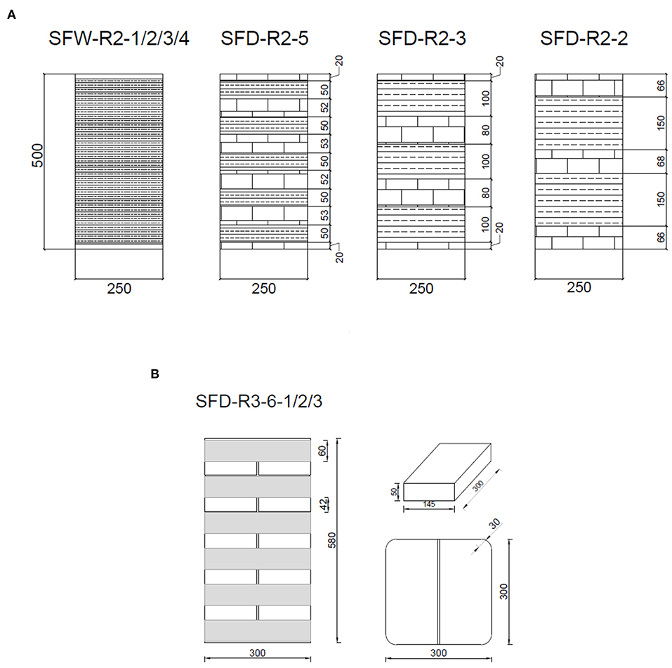
Figure 1. Geometry and schemes of strengthening: (A) GFRP and (B) CFRP (dimensions in mm).
Four additional columns were built (square cross-section of 300 × 300 mm and 580 mm height). An unconfined column was tested to determine the compressive strength of the unreinforced masonry, namely SFC-4. The remaining three columns were wrapped with CFRP-sheets (see Figure 1B), using the same scheme, and tested under axial compression until failure, namely SFD-R3-6-1, SFD-R3-6-2, and SFD-R3-6-3. Before the CFRP-wrapping, the corners were rounded by using a 30 mm curvature radius.
The mechanical properties of the materials were experimentally determined. Concerning the unidirectional GFRP strips, tensile test on five samples were performed according to ASTM D7565 recommendations (see ASTM Committee D-30 on Composite Materials, 2010) by adopting a universal machine with displacement control and maximum load capacity of 150 KN. Test velocity was equal to 2 mm/min. An average tensile strength equal to 1,605 MPa with a standard deviation of 147 MPa was detected (referred to dry thickness). The average value of the elastic modulus was 74,143 MPa with a standard deviator of 4,683 MPa, as measured by using and electrical extensometer. The ultimate strain was 2.16%. Similarly, CFRP strips have also been characterized. The actual tensile strength, ultimate tensile strain and elastic modulus of CFRP coupons were assessed in 4,216.06 ± 688.8 MPa, 2.00 ± 0.1% and 210.8 ± 23.75, respectively (average ± standard deviation).
Five limestone blocks, with dimensions of 30 × 120 × 20 mm, were tested in bending according to UNI 9724-4. Average bending strength was valuated equal to 6.0 MPa with standard deviator of 0.5 MPa. Compressive strength of 18.60 MPa (standard deviator equal to 2.06 MPa) was evaluated from compression tests on 70 × 70 × 70 mm specimens. Five prisms of mortar with dimensions of 40 × 40 × 160 mm were tested according to UNI EN 196-1. The average flexural strength was 4.56 MPa with a standard deviator equal to 0.96 MPa; while, the average compressive strength was equal to 7.8 MPa with a standard deviator of 0.9 MPa (class of mortar was M3 according to the Italian Code). The mechanical characterization of the masonry was performed by testing five triplets made of stone blocks (100 × 150 × 30 mm) and mortar joints of 10 mm thickness. The average compressive strength resulted equal to 13.6 MPa with a standard deviator of 1.0 MPa.
Test Set-Up
All the specimens were tested until failure under uniaxial centered compressive loading. The load was applied by using a jack activated by a manual pump and measured by a resistive load cell with a maximum payload of 2,000 kN. Two LVDTs (Linear Variable Differential Transducers) quantified the longitudinal displacement. The fiber deformations in GFRP strips were evaluated by bonding electrical strain gages in the fiber direction (see Figure 2A); while lateral deformation in the confined and un-confined zones has been recorded for the carbon fiber confined specimens according to Figure 2B.
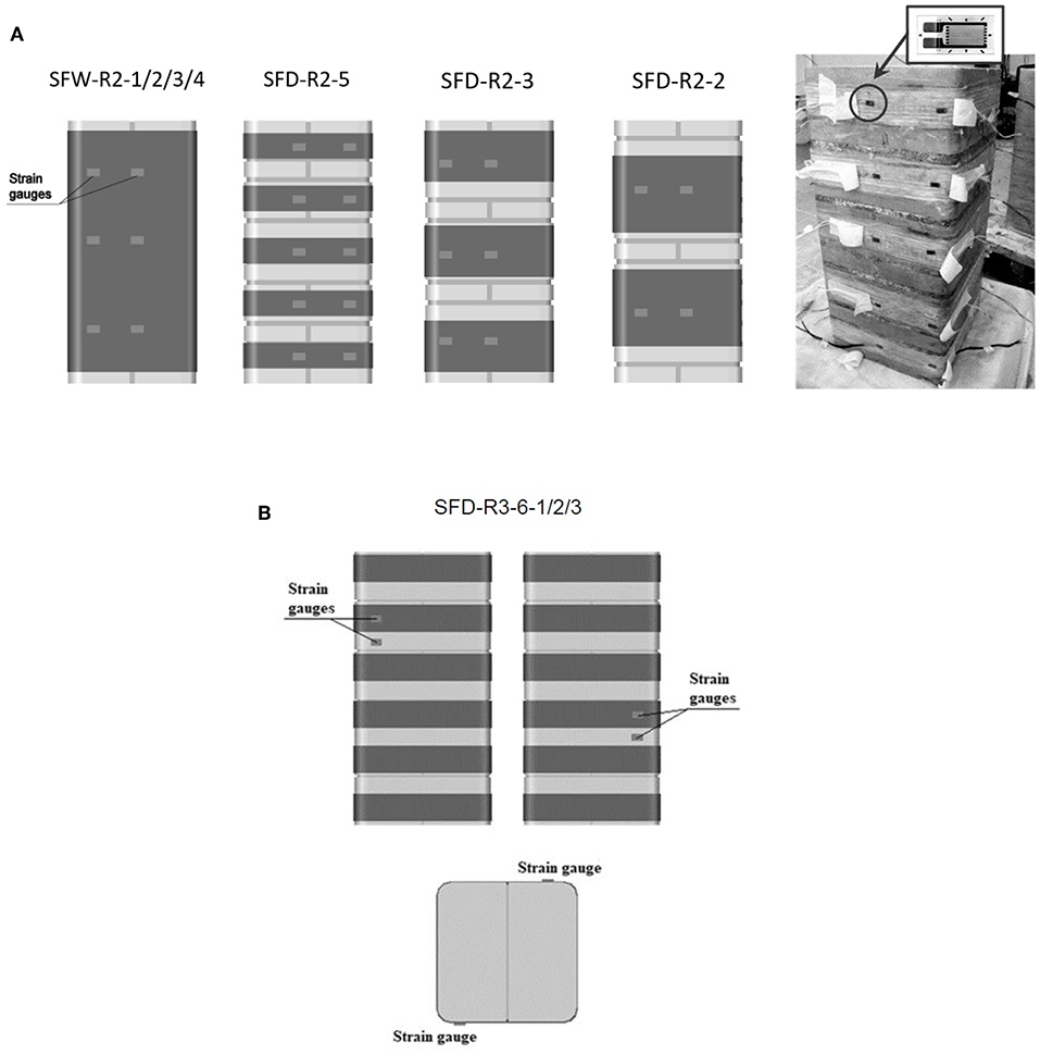
Figure 2. Locations of the strain gages: (A) GFRP and (B) CFRP.
The sample was located between two 30 mm thick steel plates, able to share the punctual load from the hydraulic jack into a uniformly distributed load on the gross section of the column. Among the steel plates, placed at the ends of the column, a double sheet of MylarTM has been interposed in order to make negligible the friction between the masonry and the load plates. A load cell and two LVDTs measured the vertical load and the corresponding longitudinal displacement, respectively. Finally, an external electronic data logger collected the data for post-processing.
Results and Discussion
In this section, the experimental results are shown and discussed. The theoretical results based on the model of the CNR DT-200R1/2013 are computed and compared with the experimental outcomes. The un-reinforced columns (SFC-1, SFC-2, and SFC-3) maintained their integrity without highlighting macro cracking up to a load of about 35 kN. At higher loads the presence of cracks was detected as well as their progress with the increasing load, up to the crisis by crushing. The average strength of the samples was equal to 6.9 MPa, showing a low standard deviation (COV = 6.6%). As expected, the variation coefficient related to the axial ultimate deformation was higher (24.6%). In fact, the deformation is related to the cracking patterns of the samples, which determines the progressive reduction of axial stiffness and, as expected may present relevant variation even comparing similar specimens. The typical failure mode of the unreinforced samples is shown in Figures 3A–C, referring to the sample SFC-3.
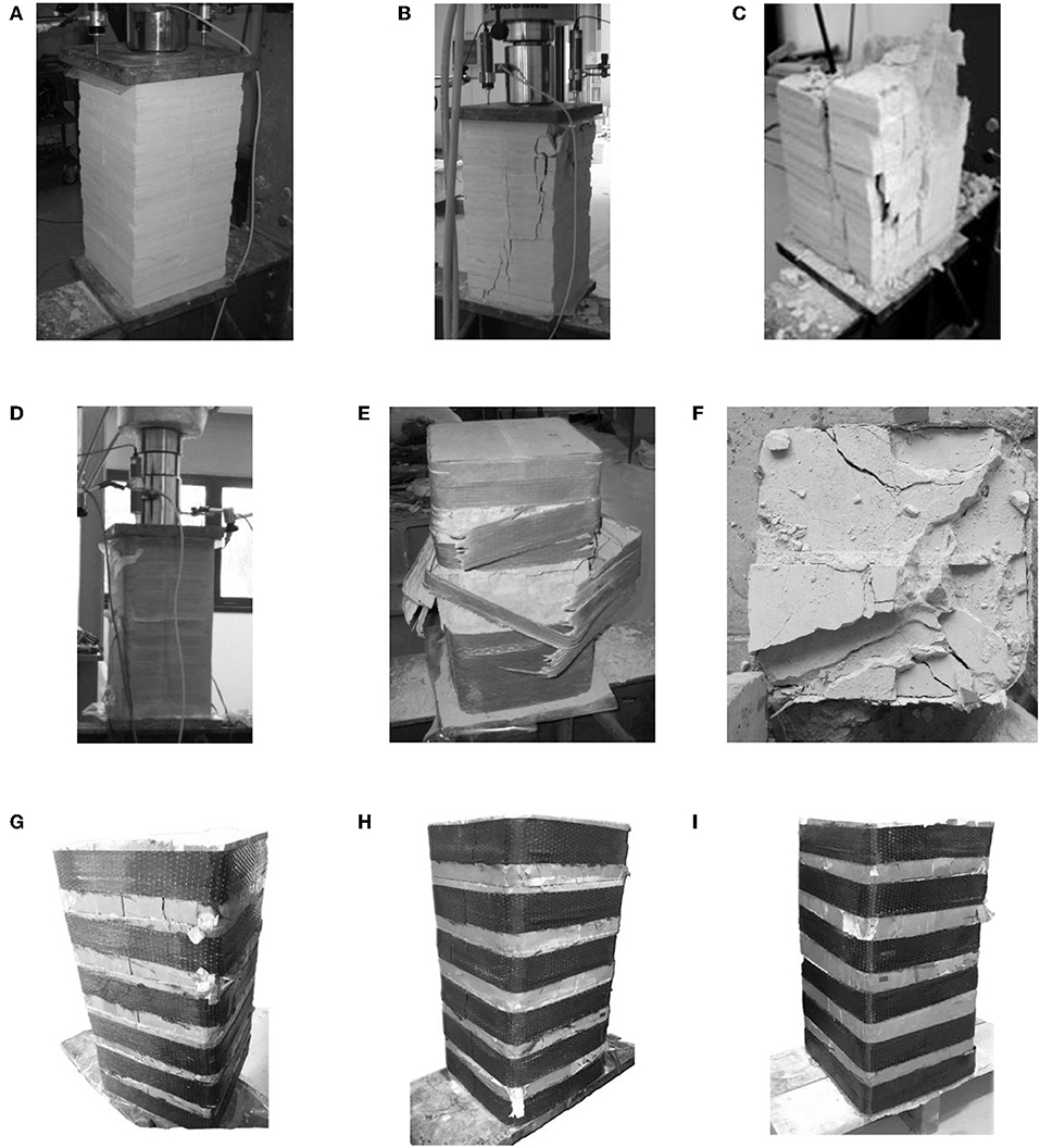
Figure 3. Failure modes of the specimens: (A) unconfined sample of the SFC series, (B) crack pattern of SFC-3, (C) failure of SFC-3, (D) reinforced sample of the SFW series, (E) failure of the fibers, (F) crack pattern of the cross section of the column, (G) SFD-R3-6-1, (H) SFD-R3-6-2, and (I) SFD-R3-6-3.
Control specimen used for carbon confined masonry, namely SFC-4, exhibited a brittle failure mode with a compressive axial strength of 8.02 MPa and a relative axial strain of 0.33%. Cracks stated in the mid-height of the sample and immediately propagated in the vertical direction along the entire column. A limited number of continuous cracks has been observed per face (i.e., one or two). The axial stress vs. lateral strain relation was not possible to be completely detected because of the premature crack development near to the measuring strain-gauges.
In those samples with GFRP continuous wrapping the average value of the compression strength was nearly double of that of control samples. The increase in terms of average axial ultimate deformation was equal to 450%. The crisis of the specimens, shown in Figures 3D–F, occurred for the progressive breakage of the glass fibers, which started at the cross-section angles, where the confining pressure is higher. In Figure 3F, the damage of the cross section after testing can be observed. In that figure, the presence of cracks delimiting the regions presumably subjected to a greater confining pressure (regions at the corners) is evident; this confirms the reliability of the theories based on the estimation of a confined volume that, among other variables, is closely related to the shape of the section of the column according to CNR DT-200 R1/2013 and experimental evidence in Aiello et al. (2009).
In the case of discontinuous confinement, different behaviors in terms of ultimate strength and ultimate axial strain were observed, although the crisis has been caused in all cases by the tensile rupture of the GFRP strips. The sample with five confining strips, differently from the others, showed a crisis of the fibers originated also along the cross-section as well as at the corners. Although the amount of fibers in the three analyzed cases was the same, when a more diffused reinforcement has been applied (only two strips) a greater efficacy has been registered, when compared to the case of three or five strips. The mentioned differences may be considered quantitatively modest with respect to the maximum load reached, while they are more significant with reference to the axial deformation capacity and failure mode. However, a broader experimental campaign is needed in order to achieve results of general validity. A difference between the averaged data of about 20% between the compressive strength obtained for continuous and discontinuous wrapping was detected. In the case of discontinuous reinforced columns, a negligible difference has been detected in terms of ultimate strain in comparison with the columns with continuous wrapping.
In Figure 4, the experimental axial stress vs. axial strain curves of all tested specimens (GFRP-confined, CFRP-confined and unconfined columns) are shown, being the strain value, the average of the measurements recorded by the LVDTs.
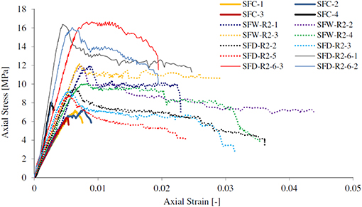
Figure 4. Stress-strain experimental behavior of all tested columns.
The Figure 4 clarifies the substantial change of the stress-strain behavior of the un-confined and confined columns with various strengthening configurations. For modest values of the load, the confinement contribution is not effective. In fact, there are not significant differences in the pseudo-linear initial range due to the modest contribution of the passive reinforcement in terms of stiffness. When the peak load is reached, the un-reinforced columns present a relevant reduction of stiffness up to the fragile rupture, namely the post-peak behavior is not appreciable. Instead, in the case of the strengthened columns, the difference of the post-peak behavior is more significant. In that phase, a “softening” stage can be observed for the case of discontinuous confinement while a “pseudo-plastic” behavior can be appreciated for the continuous wrapping, even if with different extension within the tested specimens. The discontinuous confining configuration represented by sample SFD-R2-5 provided the minor value of ultimate displacement while quite same values were observed for SFD-R2-2 and SFD-R2-3. It is worth to mention that for SFD-R2-5 premature cracks appeared along the unconfined bottom region that avoided to exploit the confinement at global level. Similarly, samples SFD-R2-2 and SFD-R2-3 reached comparable maximum value of axial force slightly greater of SFD-R2-5. The general behavior is coherent with Smith et al. (2010) and Micelli et al. (2014). Regardless of the differences, however, it is important to emphasize that the FRP provides ductility to the column, that maintains a high load-bearing capacity, while exhibiting a progressive damage. The difference between the case of the continuous and discontinuous jacketing is linked to the fact that the unconfined regions undergo a widespread cracking with a consequent higher reduction of stiffness. In this case the behavior appears intermediate between that one of a confined solid and the one of a cracked solid free to expand transversely.
The post-testing appearance of the carbon confined specimens is shown in Figures 3G–I. At the early stages of loading, the noise related to the micro-cracking of masonry core was recognizable as well as the manifestation of the cracks was evidently distinguished. Prior to the failure, cracking noises from the carbon-fiber were frequently and clearly heard. The failure pattern of CFRP-wrapped specimens was mainly related to the cracking of the masonry in the non-confined region.
The SFD-R3-6-1 specimen was externally wrapped with one layer of CFRP (vertical coefficient of efficiency kV = 0.86) and characterized by a rounded corner radius of 30 mm. It exhibited a compressive strength of 16.37 MPa and an ultimate axial strain of 0.025 (see Figure 5A). By means of the strain-gauge placed on the strip, it was possible to detect the ultimate lateral strain in the confined cross-section equal to 0.011. While, the axial strain corresponding to peak axial stress was 0.007. The strain-gauge located in the un-confined zone did not worked properly. The SFD-R3-6-2 specimen had a compressive strength of 16.04 MPa and an ultimate axial strain of 0.019. The ultimate lateral strain in the confined zone was equal to 0.006, while 0.0018 was the strain measured in the unconfined. Moreover, the axial strain corresponding to peak axial stress was 0.007 (see Figure 5B). From the curves in Figure 5, it possible to observe that the average ultimate lateral strain in the confined zone was equal to εlf,u = 0.012 ± 0.006, which was lower than the ultimate tensile strain of straight specimens. Similarly, for the columns reinforced with GFRP, the ultimate lateral strain in the confined zone was lower than ultimate tensile strain, but the glass-fibers failure was occurred for the corner effect (see Figure 3E).
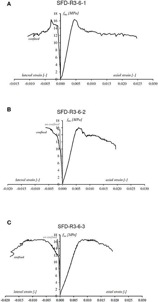
Figure 5. Experimental axial stress–strain curves for: (A) SFD-R3-6-1, (B) SFD-R3-6-2, and (C) SFD-R3-6-3.
In Table 1, all the experimental results are illustrated; symbols are listed-down:
• PMAX is the peak value of the compressive load,
• ΔHMAX is the value of the maximum axial displacement of the column,
• σMAX is the value of the compressive strength,
• εMAX is the value of the maximum axial strain at the ultimate conditions,
• σfmax/σ0max is the ratio between the strength of the confined column and the average strength of the un-confined ones;
• ΔHfmax/ΔH0max is the ratio between the maximum axial displacement of the confined column and the average value of the un-confined ones.
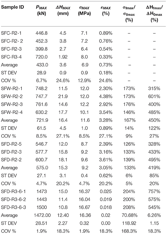
Table 1. Experimental results.
Finally, the stress-strain behavior associated to the GFRP and CFRP confined masonry specimens is shown in Figure 6. The sample SFD-R2-5 was not considered, since it showed a premature failure, due to load concentration, and ineffective confinement. The axial strength of the confined masonry was normalized by referring to the axial strength of the relative (i.e., same geometry) un-confined masonry. Overall, it can be distinguished three different phases. In the first one, the behavior of the wrapped masonry is mostly pseudo-linear and similar to the un-confined masonry. In the second phase, as the masonry core dilates and the wrap is gradually activated, a tensile stress is induced within the composite reinforcement. At the same time, a confining stress on the masonry core is acting. In the third phase, the wrap is fully activated and the confinement stress increases proportional to the stiffness of the wrap, but because of the damaging in un-confined regions, the strength decreases as axial strain increase (softening branch of the curve). So, the second and third branches are typically non-linear.
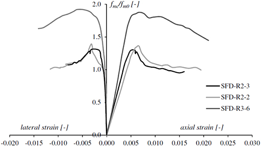
Figure 6. Fiber effect with respect to the confinement effectiveness.
It can be observed that, in the case of GFRP-confined specimens, the higher is the coefficient of vertical efficiency the higher is the axial strength and maximum strain, as expected. Furthermore, the average curve of the CFRP-confined specimens presented average axial strength and strains higher than GFRP-confined columns. Thus, the different curves are consistent with the coefficient of vertical confinement efficiency.
Comparison With CNR DT−200 R1/2013 (CNR, 2013)
The Italian National Research Council (CNR), provides the design confined strength, according to the analytical model of Equation (1):
where:
• fmcd is the design compressive strength of the FRP confined member;
• fmd is the design compressive strength of the unconfined masonry;
• k′ is the not dimensional coefficient of efficiency of the confinement;
• is the effective confinement lateral pressure;
• α1 is a coefficient equal to 0.5 if additional experimental data are not available.
The value of the k′ coefficient is calculated with the Equation (2):
where:
• gm is the masonry mass-density, here measured equal to 1,500 kg/m3;
• α2 and α3 are coefficients equal to 1.0 if further experimental data are not available.
The effective confining pressure, fl,eff, is a function of cross-sectional shape and the FRP-system and is computed according to Equation (3).
Where keff is the coefficient of geometric (volumetric) efficiency, which can be evaluated as the product of kH and kV that are the horizontal (depending on the shape of the cross-section) and vertical (depending on the type of wrapping) coefficient of efficiency of the confinement, respectively; fl is the value of the confining pressure due to the FRP material. In the case of prismatic columns, like in the case of the present study, named with b and d the values of the dimensions of the transversal cross-section, the ultimate value of the confining pressure is established by the Equation (4).
This formulation puts in relationship the pressure of confinement with the quality and the type of FRP material as also with the geometry and the scheme of confinement. In the case of continuous confinement and square cross-section, the Equation (4) is simplified.
With reference to the variables and the equations that are based on the model of the CNR, all the partial safety factors were set equal to 1. Thus, the values of the strength of the confined masonry were those of the pure analytical model. Table 2 shows the comparison between the experimental results from the reported experimentation (i.e., Castori et al., 2012; Micelli et al., 2014), and those obtained according to the analytical model of the CNR DT 200 R1/2013.
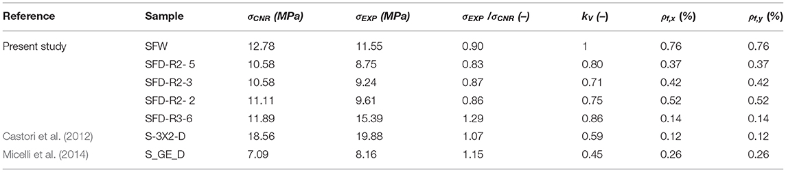
Table 2. Comparison between experimental results and theoretical model from CNR DT 200 R1/2013 (CNR, 2013).
In Table 2 it can be seen that the experimental results are in good agreement with the theoretical CNR provisions.
Proposed Analysis-oriented Model
In this section an analytical model for predicting the whole axial stress-strain behavior of FRP-confined masonry is provided and discussed valid for the case of partially-wrapping. Moreover, the role of the external discontinuous FRP-wrapping is focused. The model is able to take into account the confinement effectiveness related to the number of FRP-strips and to plot the relative stress–strain law.
The existing models can be classified into two broad categories, namely Design-Oriented Models (DOMs) and Analysis-Oriented Models (AOMs). In the first category, the compressive strength and the ultimate axial strain are predicted by using equations calibrated through experimental results. In the second category, stress–strain curves of FRP-confined masonry are generated by using an incremental numerical procedure (i.e., closed-form equation). An active confinement model is used for evaluating the axial stress and strain law of a family of passively confined column, corresponding to different fixed levels confining pressure. The target law consists in a curve crossing this family of curves. In this sense, the gradual increase of axial loading produces a consequent increase of FRP-confining action, caught by the model. The interaction between the column and the FRP confining material is explicitly accounted by equilibrium and radial displacement compatibility considerations.
In 1988, Mander et al. offered a stress–strain model for confined solid concrete members subjected to axial compressive force (Mander et al., 1988). The model utilizes the equation given by Popovics in 1973 in order to accomplish the shape of the ideal curve representing a confining pressure step, originally developed for concrete (Popovics, 1973). The stress-strain behavior of FRP-confined masonry is assumed to cross a group of theoretical curves. Each one represents the mechanical behavior of FRP-confined concrete for a different level of constant confining pressure. A bi-linear-like curve, with hardening post-peak branch, resulted from this theory. Based on the Mander's approach, a new Analysis-Oriented Model (AOM) for FRP-confined masonry is developed herein. A series of stress-strain curves, of an actively confined masonry (i.e., non-null confining pressure), are employed (see Figure 7). The axial stress-strain curve of the FRP-confined masonry is then obtained through an incremental approach, by crossing the above-mentioned family of stress-strain curves. The main innovative contribution consists in assuming the non-linearity of the axially loaded masonry by introducing a damage index (D). It makes the model able to catch the potential softening post-peak behavior of FRP-masonry by imposing the crossing through confining pressure-curves (fD, i with i = general imposed axial strain) corresponding to an increasing axial load and consequent increasing damage index (see Figure 7). Specifically, D ϵ [0;1] where 0 means undamaged, 1 means completely damaged and the numbers in between correspond to the progressive status of cracking development.
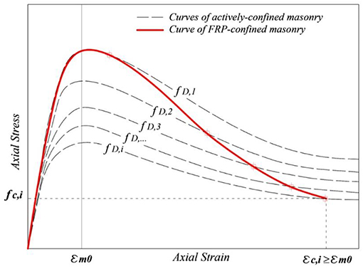
Figure 7. Main concept of the proposed AOM: constant confining pressure family-curves (dots and gray lines) and FRP-masonry behavior (red line).
The approach requires the lateral-to-axial strain relation (i.e., Poisson's ratio, υc) of the FRP-confined masonry as an input. If the lateral-to-axial strain relationship is known, for a given axial strain (εc,i), then the corresponding lateral strain (εl,i), can be determined. The circumferential stress in the FRP can then be trivially calculated by using this strain. The actively confined masonry stress–strain i-curve, corresponding to this confining pressure (fl,i) and to the damaged (if the un-confined axial strength has been exceeded) masonry strength (fD,i), can be assessed. This can be used to determine the axial stress of FRP-confined masonry (fc,i) as the peak of the curve itself, for the given axial strain step (εc,i). The confining pressure increases continuously with the axial strain increase and the behavior of the damaged masonry varies according to the damage index. These iterating steps should be repeated to generate the entire stress-strain curve. Finally, the stress-strain curve of FRP-confined masonry terminates at the point where the damage of the column reaches a fixed tolerance (e.g., toll2 < 10%). The accuracy of AOM is very sensitive to both the active confinement base curves and the lateral-to-axial strain relationships used in the model. In the following, the process for determining the Poisson's ratio of the FRP-confined masonry is presented. The expressions, used by the proposed AOM for establishing the actively confined masonry curves, are reported and commented, as well as, the formulations to model the lateral-to-axial strain relationship of the FRP-confined masonry.
The model is proposed on the basis of the elastic interaction between the masonry and the confining-device by imposing equilibrium conditions and radial displacement compatibility at the interface between the masonry-core and the outer FRP-jacket. Whereby, the dependence of the lateral strain to the axial strain can be explicitly considered through radial displacement compatibility and equilibrium equations. When masonry is free to laterally expand, due to imposed uniform axial strain εc, the radial and axial strain are linked through the following relationship, namely Equation (5):
where υc is Poisson's ratio of the masonry.
Generally, the Poisson's ratio υc is used to obtain the lateral strain at a given axial strain. The dilation of confined masonry is reduced by the confinement itself. Therefore, Poisson's ratio at a given axial strain level is lower in the presence of confining pressure. By referring to a tri-axially loaded concrete cylinder, under different confining hydrostatic pressures, the relative curves (in terms of axial and lateral strain vs. axial stress) can be fitted with a second-order polynomial and so provide a simplified linear relationship for νc under a constant confining pressure (e.g., in Lignola et al., 2008). Similarly, the computation of νc as a function of the FRP-provided confining pressure for masonry column is needed. The confining pressure, according to the mentioned CNR Italian Guidelines for FRP-reinforcement (CNR, 2013), was computed with Equation (6):
where:
• nf is the number of FRP layer(s);
• tf is the thickness of a single FRP layer;
• Ef is Young modulus of elasticity of the FRP in the direction of fibers;
• d is the masonry cross-section diameter;
• εf is the lateral strain of the column at each level of stress.
The model proposed by Krevaikas and Triantafillou (2005) for FRP-confined masonry, provided the linear equation for the peak strain of confined masonry, εmc, in terms of according to Equation (7).
where:
• εm0 is the strain of unconfined masonry;
• fm0 is the compressive strength of unconfined masonry.
The relationship that binds the Poisson's ratio of the confined masonry to the confining pressure and the axial strain was herein obtained by analyzing experimental research data carried out by Witzany et al. (2014). The authors reported that the confining effect provided by FRP strips was evident from the comparison of experimental load vs. vertical/horizontal deformation curves. Such curves were used for determining the Poisson's ratio of confined masonry as the ratio between horizontal and vertical deformation at each level of axial stress. By considering a model with two variables, and , the Multiple Linear Regression (MLR) produces a regression surface that can be represented in a 3D-domain as schematically illustrated in Figure 8.
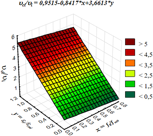
Figure 8. 3D-Surface Plot of νci/νi against fli/fm0 and εci/εcmi.
The MLR provides the relationship between and variables and the target by fitting a theoretical linear equation on the basis of experimental results by Witzany et al. (2014). In fact, it allowed to assess the analytical formulation expressed in Equation (8), which represents the 3D regression surface:
where:
• εcm is the actual peak compressive strain (evaluated for the lateral confining pressure fl);
• fm0 is the peak strength of unconfined masonry;
• ν is the Poisson's ratio of the unconfined masonry.
The flow-chart of the proposed model is reported in Figure 9 for the case of FRP-confined masonry column with discontinuous strips of which the coefficient of vertical efficiency, kV, is calculated as described by Italian Guidelines for FRP-reinforcement (CNR, 2013). In particular, three different phases can be distinguished, or rather:
1. Initialization;
2. Iterative;
3. Updating.
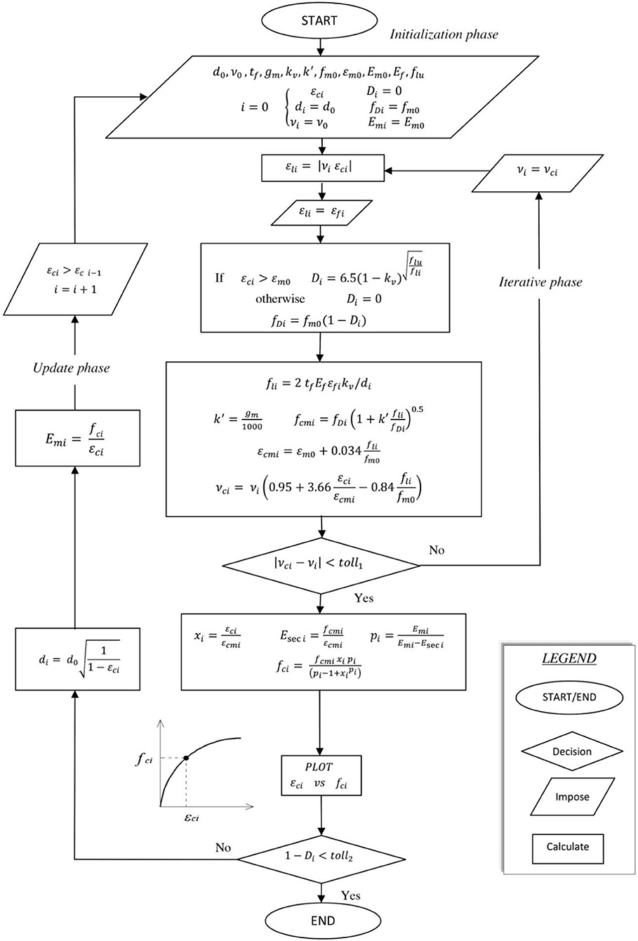
Figure 9. Flow-chart of the proposed model.
A value εci of the axial strain of the column is imposed as starting value, and increased in each next-steps. For a proper initialization the value εci can be taken equal to the axial strain of unconfined masonry, corresponding to 10% (or less) of the peak strength.
In the initialization phase (first step i = 0), the geometric and mechanical characteristics of the un-confined solid and of the fiber type utilized are assumed as follows (see Figure 9):
• d0 is the diameter of the circular cross section;
• ν0 is the Poisson's ratio of the un-confined masonry (value assumed equal to 0.25 Mastrodicasa, 1958);
• fm0 is the unconfined masonry peak strength;
• gm is density of the masonry;
• εm0 is the strain of the unconfined masonry, at peak stress;
• Em0 is the elastic modulus of the masonry;
• flu is the ultimate lateral stress;
• tf is the FRP-jacket thickness;
• kv is the coefficient of vertical efficiency;
• Ef the elastic modulus of the FRP in the fiber's direction.
The iterative phase (see Figure 9) allows the calculation of the Poisson's ratio νi of the confined masonry and the lateral strain of the confined masonry that can be computed as:
In the field of small displacements and assuming radial displacement compatibility at the interface between the column and the outer jacket, the lateral strain of the confinement jacket, εf, can be written:
The model considers the inelasticity of the column through a damage index D, affecting the value of the strength of the masonry (fm0) once the axial strain of the un-confined masonry is exceeded. In this way the decay of elastic properties due to cracking is simulated. Thus the Di value quantifies the percentage of the cracked solid core with respect to the whole column. At this scope, the Equation (11) was empirically derived in order to meet the experimental post-peak slope.
The value of the axial strength of the damaged masonry is so-evaluated as:
The active confining pressure fli, also considering the coefficient of vertical efficiency, can be evaluated with:
The compressive strength, fcmi, for members confined with FRP, subjected to a lateral confining pressure, is:
where .
The deformation state at i-step should be consistent with the Poisson's ratio at (i−1)-step. Therefore, the equations of the iterative phase are repeated until the following small tolerance (=1%) is found:
Once the iterative phase is concluded, the general state of axial stress fci is a function of the general state of axial strain εci given by Popovic, Popovics (1973).
Where:
• is the relative strain;
• is a secant stiffness;
• is relative stiffness parameter.
Therefore, the initial values of the diameter of the cross-section and the elastic longitudinal modulus of the confined masonry can be updated:
A further step of strain can be applied up to:
where this tolerance should represent the level of cracking propagation per each specimen.
This model is suitable to predict the behavior of confined masonry with a confining pressure equal to fli. As the axial load increases, the FRP-confinement provides a continuously increasing of the confining pressure and the damage index. It is therefore necessary to account, for different Mander-based curves, each pertaining to the damage level corresponding to the current lateral strain. According to this mechanical occurrence, the complete stress–strain curve crosses a family of Mander's curves, as introduced above.
Model Consistence and Robustness
The effect of different parameters on the global stress-strain response of the confined masonry was evaluated by performing some parametric evaluations by using MatLab habitat (see Matlab, 2014).
In Figure 10A comparison is given regarding the confined masonry stress-strain curves for different kV values. Specifically, the axial strength of confined masonry has been normalized by unconfined masonry strength. The Figure 10A clearly shows that, for the same volume of FRP material bonded to the column, the kV = 0.90 (column near to fully wrapped) is more effective in increasing the ultimate compressive stress and ultimate strain and ductility, as well as. If the kV coefficient increases, the effectiveness of confinement increases and vice versa. It is important to highlight the variation of the post-peak slope behavior. In fact, at the minimum value of kV a dramatic drop of the axial stress is appreciated while, when the kV value increased, the post-peak axial stress decreased more gradually and stabilized, evidencing the capacity of the column of maintaining a higher residual strength and more significant ductility. It is reasonable that the effect of confinement is grown as the kV coefficient increased; therefore, the model appears able to predict correctly the behavior of confined columns.
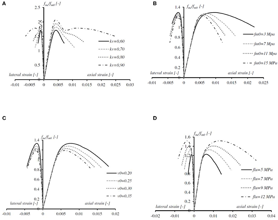
Figure 10. Parametric analysis for axial strength increase: (A) effect of the coefficient of vertical efficiency kV, (B) effect of the un-confined masonry strength, (C) effect of the un-confined masonry Poisson's ratio, and (D) effect of the maximum pressure provided by the FRP-jacket.
In confinement of masonry columns, the strength-increase depends on the entity of the lateral pressure exerted by the FRP-strips. In the proposed model such strength is related to the strength of the unconfined column, in fact, the FRP-confined masonry strength increases proportionally (see also Equation 1) to the fm0 (see Figure 10B). A particularly interesting feature is that, by increasing the values fm0, the gradient of the descending branch increases. Accordingly, at a given stress level, larger axial deformations are obtained for lower fm0. The values of the confined masonry strength are strongly dependent on the initial properties of the unconfined masonry. In this perspective, the graphs evidences that the FRP-confinement is more efficient when applied to poor-quality masonry (i.e., low compressive strength), especially in ductility enlargement.
The Figure 10C shows the lateral and axial strains vs. axial stress curves for different ν0 (Poisson's ratio of the un-confined masonry) values. The axial strain is almost similar, or slightly rising, up to peak unconfined masonry stress. After that peak point, the axial strain grows more significantly according to the lesser ν0. The lower is the Poisson's ratio, the higher is the axial deformability of the element for similar levels of dilation. The higher is the lateral deformability, the smaller is the strength enhancement. The shape of the curve (i.e., global behavior) appears to be unaffected.
The effect of the tensile strength of the confining FRP, in terms of hoop pressure, is shown in Figure 10D. It can be observed that an increase in the strength of the FRP-confinement resulted in an increase in ultimate strength and strains at peak strength. In other words, larger FRP cross-section or equivalently stronger fibers lead to higher load increase. So, the FRP-effect appears to be properly modeled. The slopes of the descending branch of the curves were fairly similar.
The non-linearity of the masonry itself is considered in the proposed model by introducing a damaging index D used for reducing the axial strength of the column due to progressive cracking. In turn, this assumption influenced the whole performance of the proposed formulation so, a specific parametric analysis has been computed and discussed herein.
The Figure 11A shows that the stiffness of the FRP-wrap plays a significant role on the damage condition of the masonry. The scalar variable D is zero for the virgin material (which means undamaged material), but when the axial load and then the axial strain increase, the damage index increase testifying the crack-opening. The parametric analysis in Figure 11A shows that by increasing the axial strain, higher values of D are detectable for larger Young's modulus Ef. It is relevant to observe that, for a given axial strain level, the damaging of the FRP-confined masonry column with discontinuous strip increases when Ef increases. So, in discontinuous confinement of masonry columns, more performable fibers (in term of the FRP-stiffness) cause a premature presence of cracks in the un-confined regions. This is valid for discontinuous confinement, since damage evolves differently when masonry columns is almost completely wrapped (e.g., in kV = 0.90), as shown the Figure 11B.
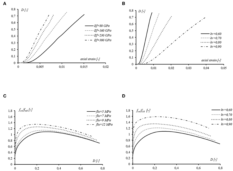
Figure 11. Damage effect: (A) elastic modulus of the FRP, (B) vertical confinement effectiveness, (C) the maximum pressure provided by the FRP-jacket, and (D) vertical efficiency coefficient.
The graph in Figure 11B allows to observe the reduction of the column damage due to the improved vertical FRP-effectiveness (kV value). The FRP-confinement acts by containing the lateral expansion of the masonry core, so the evolution of cracking changes significantly and it grows moderately when the number of FRP-sheets is magnified. This also explains the higher ductility of wrapped columns with higher kV.
In Figure 11C, the graph shows that, by varying the confinement maximum pressure provided by the FRP-jacket, the damage development assumes comparable trends. In particular, for low D-value (i.e., in between 0 and 0.2) stronger FRP means higher axial strength increase with respect to the un-confined masonry element. For high value of D (e.g., over 0.6) the effect of the FRP longitudinal strength appears weak; this is due to the cracking in unconfined regions, which may govern the failure mode. In fact, in the first part (ascending), all the curves show a phase of the damage growth until reaching a peak. In the second branch the damage index increases, accompanied by a decrease of confinement effectiveness. It is possible to note that, before the peak, the slope increases as the lateral pressure increases. In the descending branch all curves appear to have the same trend.
Similarly, in Figure 11D an analysis is performed in order to analyze the influence of the kV on the confinement effectiveness in a given damage index range. The curves shape is fairly similar to trend of the previous diagram. The diagram shows a direct correlation between the increase of the axial capacity and the kV itself, as expected by the proposed model. For a given damage-level, the axial strength increase is more evident for partially-wrapped columns which trends to the full-wrapped configuration. On the other hand, specimens having very low confinement ratios tend to the un-confined column behavior (see kV = 0.60 in Figure 11D).
The proposed model has been tested by varying different inputs in order to evaluate the relative output. In such way, the robustness of the iterative procedure has been proved. It is important to point-out that the explicit-philosophy of the method implies the importance of considering small calculation-step (herein in terms of axial strain) with respect to the maximum value.
Theoretical vs. Experimental Comparison and Discussion
In the present section the results provided by the presented experimental tests on FRP confinement of masonry columns have been collected and compared to the theoretical prediction of the proposed model. The main objective was the assessment of the reliability of the proposed analytical model. A set of three experiments on masonry columns confined with glass fiber and carbon fiber with different confinement schemes was carried out.
The full-response of these specimens was theoretically predicted and compared with the experimental outcomes in Figure 12. Accurate agreement was found between the measured values and the predicted response for the confined masonry compressive strength.
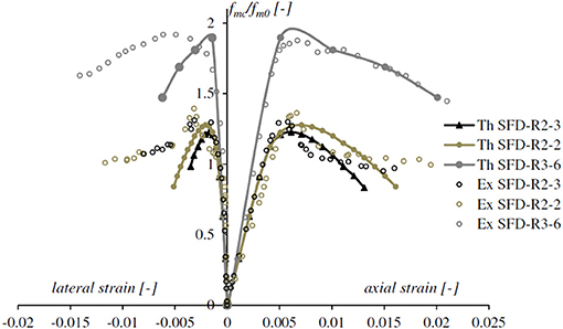
Figure 12. Theoretical predicted response vs. experimental outcome.
The experimental points are plotted to summarize the compressive strengths of the FRP-confined columns. The continuous lines denote the theoretical axial stress-strain curves of the specimens. For the confined columns the failure was induced by the local crushed masonry between the adjacent FRP-strips. The partially-wrapped specimens showed many small cracks on the masonry surface at a stress level that is equal to the unconfined masonry strength. The external part of masonry columns, between the FRP bands, started crushing while the column-core remained still undamaged. Accordingly, cracks on the masonry surface developed as the applied load increased. When the stress reached a certain high level, the masonry between the FRP bands spalled-off, while the masonry under the FRP bands and the core of the columns was still confined. Under higher loads, the masonry cracks extended, and FRP rupture occurred locally, at the corners. The partial wrapping arrangement changes the failure modes of the specimens, significantly affected the accuracy of the lateral deformation prediction (Pham et al., 2015).
The experimental average values of the axial strength and lateral strain (SFD-1-R3-6, SFD-2-R3-6, and SFD-3-R3-6) were utilized to draw the graphs in Figure 13. The lateral strain at the confined zone over that at the un-confined part vs. the relative axial stress level is reported.
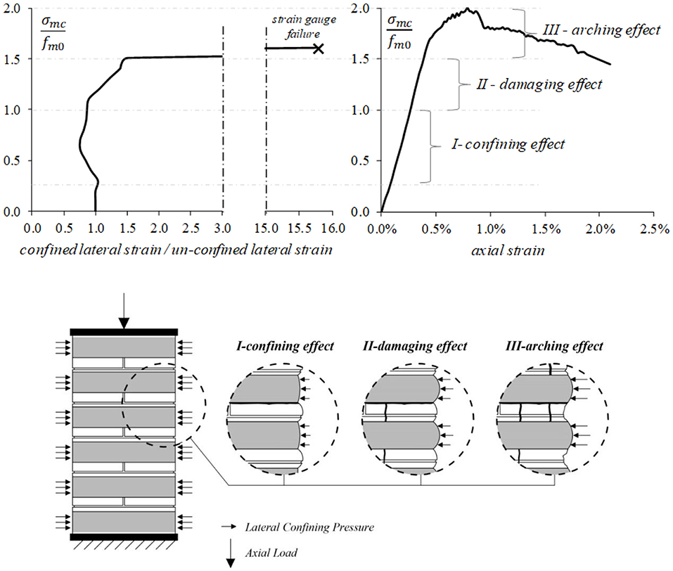
Figure 13. Cracking development phases: I-confining effect, II-damaging effect, and III-arching effect.
The partially-wrapped specimens showed a similar failure mode consisting in many vertical cracks at stress level proximal to the unconfined masonry strength. By increasing the axial stress, the masonry between the CFRP-bands spalled-off. For stress levels close to the strength of confined specimens, the masonry cracks extended with a partial failure of the CFRP-strips (fiber ruptures were clearly heard). In particular, during loading, three different phases were identified, by neglecting the range of very low axial stress levels:
I confining effect: the fibers are activated by the hoop deformation of the column. The lateral deformation appeared to be not uniform; i.e., the expansion recorded in the un-confined zones is slightly larger than that in the confined areas. In this perspective, the CFRP-confinement demonstrated to start his action (see Figure 13);
II damaging effect: when the axial strength of the unconfined masonry was reached, the first vertical crack formed mainly in the unconfined regions. The trend, typified in the phase-I, was so-overturned; i.e., larger lateral deformation in the confined zones was recorded (see Figure 13). Hence, the loading produced the crack width increasing instead of further lateral deformation where the strain-gauge was bonded (unconfined region);
III arching effect (see also Zeng et al., 2018): under higher load levels, the crack pattern extended, and the number of cracks increased, as well as the entity of the crack's width. The exterior parts of the unconfined masonry were lost, and an arch-like shape cracks manifested. The arching action occurred in a form of parabola with an initial tangent slope of 45°on the area of unconfined masonry-core between the transverse reinforcements. Crack openings reached the maximum width and the deformation became more significant in the CFRPs. This trend has been reasonably maintained up to the peak load, even if, the recording has been interrupted after the strain-gauges detachment/rupture (see Figure 13).
Conclusions
The results of an experimental campaign on limestone masonry columns, confined with FRP-composite materials were presented and discussed. The experimental results have revealed, as expected, the significant beneficial effects of FRP-confinement in terms of increase in ultimate load and axial strain. The most significant result is related to the variation of the axial load-displacement behavior in absence or presence of confinement. While the unreinforced columns show a brittle behavior, in the case of full confinement or hoops, the curves exhibit a significant post-peak branch that testifies a considerable dissipation capability accompanied by a load retention. The experimental data were compared with the theoretical results obtained from the analytical model underlying the recommendations of the technical document CNR DT200/R1 2013.The theoretical evaluations, based on CNR, of the ultimate strength of FRP-confined masonry, were found to be in an accurate agreement with the experimental outcomes.
In addiction a new theoretical model was formulated and proposed, aiming to predict the mechanical behavior of FRP-confined masonry with full or discontinuous jacketing. The model takes into account the strengthening scheme through the introduction of the vertical efficiency index. The non-linear behavior of masonry, due to progressive cracking, was governed by using a damage index. The model is able to quantify the difference of the Poisson's effect in the unconfined and FRP-confined regions of the columns. The robustness and consistency of the model was tested by performing parametric analyses. A good accuracy of the theoretical predictions, respect to the tested columns, was found.
Data Availability Statement
All datasets generated for this study are included in the article/supplementary material.
Author Contributions
FM and MA worked on the experimental program while AC and ML developed the theoretical predictions.
Conflict of Interest
The authors declare that the research was conducted in the absence of any commercial or financial relationships that could be construed as a potential conflict of interest.
References
Aiello, M. A., Micelli, F., Angiulli, R., and Corvaglia, P. (2012). “Masonry circular columns confined with glass and basalt fibers,” in Proceedings of CICE 2012 6th International Conference on FRP Composites in Civil Engineering (Rome).
Aiello, M. A., Micelli, F., and Valente, L. (2007). Structural upgrading of masonry columns by using composite reinforcements. ASCE J. Compos. Constr. 11, 650–658. doi: 10.1061/(ASCE)1090-0268(2007)11:6(650)
Aiello, M. A., Micelli, F., and Valente, L. (2009). FRP-Confinement of square masonry columns. ASCE J. Compos. Constr. 13, 148–158. doi: 10.1061/(ASCE)1090-0268(2009)13:2(148)
Alecci, V., Briccoli Bati, S., and Ranocchiai, G. (2008). “Confining compressed pillars with FRP composites,” in Proceedings of the 3rd Conference on Mechanics of Masonry Structures Strengthened With Composite Materials- MURICO 3 (Venice), 26–33.
ASTM Committee D-30 on Composite Materials (2010). D7565/7565M Standard Test Method for Determining Tensile Properties of Fiber Reinforced Polymer Matrix Composites Used for Strengthening of Civil Structures1. West Conshohocken, PA: ASTM International.
Cascardi, A., Aiello, M. A., and Triantafillou, T. (2017a). Analysis-oriented model for concrete and masonry confined with fiber reinforced mortar. Mater. Struct. 50:202. doi: 10.1617/s11527-017-1072-0
Cascardi, A., Dell'Anna, R., Micelli, F., Lionetto, F., Aiello, M. A., and Maffezzoli, A. (2019). Reversible techniques for FRP-confinement of masonry columns. Constr. Build. Mater. 225, 415–428. doi: 10.1016/j.conbuildmat.2019.07.124
Cascardi, A., Longo, F., Micelli, F., and Aiello, M. A. (2017b). Compressive strength of confined column with Fiber Reinforced Mortar (FRM): new design-oriented-models. Constr. Build. Mater. 156, 387–401. doi: 10.1016/j.conbuildmat.2017.09.004
Cascardi, A., Micelli, F., and Aiello, M. A. (2018). FRCM-confined masonry columns: experimental investigation on the effect of the inorganic matrix properties. Constr. Build. Mater. 186, 811–825. doi: 10.1016/j.conbuildmat.2018.08.020
Castori, G., Corradi, M., and Borri, A. (2012). “Masonry confinement with SRP composites,” in Proceedings of the International Conference on Structural Analysis of Historical Constructions SAHC (Wroclaw).
Chen, J., Ai, J., and Stratford, T. (2010). Effect of geometric discontinuities on strains in FRP-wrapped columns. J. Compos. Constr. 14, 136–145. doi: 10.1061/(ASCE)CC.1943-5614.0000053
CNR, D. T. (2013). 200 R1–2013. Guide for the Design and Construction of Externally Bonded FRP Systems for Strengthening Existing Structures. Rome: National Research Council. 10.
Corradi, M., Grazini, A., and Borri, A. (2007). Confinement of brick masonry columns with CFRP materials. Compos. Sci. Technol. 67, 1772–1783. doi: 10.1016/j.compscitech.2006.11.002
D'Ambra, C., Di Ludovico, M., Balsamo, A., Prota, A., and Manfredi, G. (2008). “Confinement of tuff and brick masonry columns with FRP laminates,” in Proceedings of the 3rd Conference on Mechanics of Masonry Structures Strengthened with Composite Materials- MURICO 3 (Venice), 232–240.
Faella, C., Martinelli, E., Paciello, S., and Nigro, E. (2004). “Experimental tests and theoretical models on tuff masonry bricks and columns confined with C-FRP sheets,” in Proceedings of IMTCR04 International Conference, Vol. 2, eds A. Nanni and A. La Tegola (Lecce), 343–359.
Iorfida, A., Verre, S., Candamano, S., and Ombres, L. (2018). Tensile and direct shear responses of basalt-fibre reinforced mortar-based materials. 15, 544–552. doi: 10.1007/978-94-024-1194-2_63
Kog, Y. C., Ong, K. C. G., Yu, C. H., and Sreekanth, P. V. (2001). Reinforced concrete jacketing for masonry columns with axial loads. ACI Mater. J. 98, 105–115. doi: 10.14359/10194
Krevaikas, T. D., and Triantafillou, T. C. (2005). Masonry confinement with fiber-reinforced polymers. J. Compos. Constr. 9, 128–135. doi: 10.1061/(ASCE)1090-0268(2005)9:2(128)
Lignola, G. P., Prota, A., Manfredi, G., and Cosenza, E. (2008). Unified theory for confinement of RC solid and hollow circular columns. Compos. Part B Eng. 39, 1151–1160. doi: 10.1016/j.compositesb.2008.03.007
Maddaloni, G., Di Ludovico, M., Balsamo, A., Maddaloni, G., and Prota, A. (2018). Dynamic assessment of innovative retrofit techniques for masonry buildings. Compos. Part B Eng. 147, 147–161. doi: 10.1016/j.compositesb.2018.04.038
Mander, J. B., Priestley, M. J., and Park, R. (1988). Theoretical stress-strain model for confined concrete. J. Struct. Eng. 114, 1804–1826. doi: 10.1061/(ASCE)0733-9445(1988)114:8(1804)
Masia, M. J., and Shrive, N. G. (2003). CFRP wrapping for the rehabilitation of masonry columns. Can. J. Civil Eng. 30, 734–744. doi: 10.1139/l03-015
Mastrodicasa, S. (1958). Dissesti Statici Delle Strutture Edilizie. Diagnosi e Consolidamento [in Italian]. Milan: Hoepli.
Matlab (2014). Matlab [Computer Software] and Statistics Toolbox Release 2014a. Natick, MA: The MathWorks, Inc.
Micelli, F., De Lorenzis, L., and La Tegola, A. (2004). FRP-confined masonry columns under axial loads: analytical model and experimental results. Br Masonry Soc. 17, 95–108.
Micelli, F., Di Ludovico, M., Balsamo, A., and Manfredi, G. (2014). Mechanical behaviour of FRP-confined masonry by testing of full-scale columns. Mater. Struct. 47, 2081–2100. doi: 10.1617/s11527-014-0357-9
Minafò, G., D'Anna, J., Cucchiara, C., Monaco, A., and La Mendola, L. (2017). Analytical stress-strain law of FRP confined masonry in compression: Literature review and design provisions. Compos. Part B Eng. 115, 160–169. doi: 10.1016/j.compositesb.2016.10.019
Minafò, G., and La Mendola, L. (2018). Experimental investigation on the effect of mortar grade on the compressive behaviour of FRCM confined masonry columns. Compos. Part B Eng. 146, 1–12. doi: 10.1016/j.compositesb.2018.03.033
Minafò, G., Monaco, A., D'Anna, J., and La Mendola, L. (2018). Compressive behaviour of eccentrically loaded slender masonry columns confined by FRP. Eng. Struct. 172, 214–227. doi: 10.1016/j.engstruct.2018.06.011
Ombres, L., Iorfida, A., Mazzuca, S., and Verre, S. (2018a). Bond analysis of thermally conditioned FRCM-masonry joints. Measurement 125, 509–515. doi: 10.1016/j.measurement.2018.05.021
Ombres, L., Mancuso, N., Mazzuca, S., and Verre, S. (2018b). Bond between carbon fabric-reinforced cementitious matrix and masonry substrate. J. Mater. Civil Eng. 31:04018356. doi: 10.1061/(ASCE)MT.1943-5533.0002561
Ombres, L., and Verre, S. (2019). Flexural strengthening of RC beams with steel-reinforced grout: experimental and numerical investigation. J. Compos. Constr. 23:04019035. doi: 10.1061/(ASCE)CC.1943-5614.0000960
Pham, T. M., Hadi, M. N., and Youssef, J. (2015). Optimized FRP wrapping schemes for circular concrete columns under axial compression. J. Compos. Constr. 19:04015015. doi: 10.1061/(ASCE)CC.1943-5614.0000571
Popovics, S. (1973). A numerical approach to the complete stress-strain curve of concrete. Cement Concrete Res. 3, 583–599. doi: 10.1016/0008-8846(73)90096-3
Shrive, N. G. (2006). The use of fibre reinforced polymers to improve seismic resistance of masonry. Constr. Build. Mater. 20, 269–277. doi: 10.1016/j.conbuildmat.2005.08.030
Smith, S., Kim, S., and Zhang, H. (2010). Behaviour and Effectiveness of FRP Wrap in the Confinement of Large Concrete Cylinders. J. Compos. Constr. 14, 573–582. doi: 10.1061/(ASCE)CC.1943-5614.0000119
Witzany, J., Cejka, T., and Zigler, R. (2014). Failure mechanism of compressed short brick masonry columns confined with FRP strips. Constr. Build. Mater. 63, 180–188. doi: 10.1016/j.conbuildmat.2014.04.041
Keywords: FRP, confinement, analysis-oriented model, testing, discontinuous confinement
Citation: Cascardi A, Lerna M, Micelli F and Aiello MA (2020) Discontinuous FRP-Confinement of Masonry Columns. Front. Built Environ. 5:147. doi: 10.3389/fbuil.2019.00147
Received: 07 October 2019; Accepted: 11 December 2019;
Published: 09 January 2020.
Edited by:
Giovanni Minafò, University of Palermo, ItalyReviewed by:
Salvatore Verre, University of Calabria, ItalyAlessia Monaco, Polytechnic University of Turin, Italy
Marco Filippo Ferrotto, University of Palermo, Italy
Copyright © 2020 Cascardi, Lerna, Micelli and Aiello. This is an open-access article distributed under the terms of the Creative Commons Attribution License (CC BY). The use, distribution or reproduction in other forums is permitted, provided the original author(s) and the copyright owner(s) are credited and that the original publication in this journal is cited, in accordance with accepted academic practice. No use, distribution or reproduction is permitted which does not comply with these terms.
*Correspondence: Alessio Cascardi, YWxlc3Npby5jYXNjYXJkaUBpdGMuY25yLml0