 Azadeh Jaberi Jahromi
 Alireza Valikhani
 Islam M. Mantawy
 Atorod Azizinamini2
- 1Washington State Department of Transportation, Olympia, WA, United States
- 2Civil and Environmental Engineering Department, Florida International University, Miami, FL, United States
Closure joints are commonly used in the bridge deck to connect two adjacent prefabricated elements in accelerated bridge construction. The current practice of closure joints utilizes the use of different materials such as normal-strength concrete and ultrahigh performance concrete (UHPC) with the use of different reinforcement details such as straight bars, hooked bars, and headed bars. The design of closure joints to meet the strength limit state is quite simple; however, the design of a service life for these joints is quite challenging. A framework for the service life design of closure joints in bridges, built using accelerated bridge construction techniques, is developed in this paper. This framework includes several steps: (1) identification of project requirements especially those that influence the service life of closure joints; (2) identification and selection of feasible closure joint types suitable for the project requirements; (3) identification of factors that influence the service life of closure joints along with the mode of failures and consequences; (4) identification of suitable approaches or strategies for mitigating failure modes or assessing the risk of damage; (5) modification of closure joint detail using mitigation strategies that may result in the development of several alternatives and options for each closure joint type; (6) estimation and comparison of service life design for each modified alternative using finite or target service life approaches; and (7) conduction of life cycle cost analysis for each modified alternative along with the selection of the optimum closure joint details to meet both strength and service life demand. This framework is used in practical design implementation, for example, the 1,400-ft-long bridge in Boston, MA, United States. Several closure joints details were studied under this research such as the use of normal-strength concrete with straight bars, 180° hooked bars, 90° hooked bars, and headed bars along with the use of ultra-high performance concrete with straight bars. The mitigation strategies for service life design of closure joints include (1) increasing deck and closure joint thickness by 0.5 in. and the use of bottom sealer; (2) the use of 0.5 in. of UHPC overlay and bottom sealers; (3) increasing the deck and closure joint thickness by 0.5 in. and the use of membrane and asphalt overlay along with bottom sealer; and (4) increasing the deck and closure joint thickness by 0.5 in. and the use of stainless steel in deck panels and closure joints. The least life cycle cost is obtained using UHPC overlay and bottom sealers, and the use of UHPC in closure joints leads to a reduction in repair intervals. This paper summarizes the outcome of the design for the service life of those closure joints comparatively.
Introduction
Accelerated bridge construction (ABC) is a construction technique that uses innovative design, materials, and construction methods to reduce construction time for both new construction and rehabilitation (Culmo et al., 2011). Many advantages can be achieved when utilizing ABC such as minimizing traffic disruptions and increasing safety for workers, vehicles, and the traveling public. Prefabricated bridge elements are the most ABC popular techniques, which also include lateral slides and self-propelled transporters. In this approach, large segments of bridges are prefabricated offsite, are transported to the final site, and are connected using dry or wet connections. The prefabricated elements include deck modules, pile caps, abutments, approach slabs, and intermediate bents. These systems require joints between elements, and some transportation agencies have expressed concern regarding the durability and structural integrity of these joints (Culmo et al., 2011). Full-depth deck panels and pretopped modular units are the most popular prefabricated elements; however, these elements are connected in the field using closure joints. Closure joints form by steel reinforcement extended from two adjacent panels that are spliced after the placement of each panel, and then normal-strength concrete (NSC) (Badie and Tadros, 2008; Culmo, 2009; Aktan and Attanayake, 2013; Culmo et al., 2013) or ultra-high performance concrete (UHPC) (Yuan and Graybeal, 2014) or polymer concrete (PC) (Mantawy et al., 2019) is cast to create a continuous riding surface. Closure joints are structural components that transfer moment and shear between deck panels through longitudinal or transverse joints, which run parallel or perpendicular to traffic direction, as shown in Figure 1. The efficacy of these joints can be affected by environmental and structural degradations (Graybeal, 2010). Durability issues have been encountered in longitudinal joints that use welded steel tie plate connectors. A leaking crack can also be a potential hazard for vehicular traffic on bridges with highway underpasses (Badie et al., 1999; Graybeal, 2010). To control cracking in closure joints, researchers proposed the use of closely spaced reinforcement in closure joints, which provides better stress distribution when compared to widely spaced steel reinforcement (Gull et al., 2014); in addition, minimizing the width of closure joints reduces durability issues related to shrinkage. This paper presents a generic framework for service life design for closure joints in ABC and provides a practical design implementation example to empower and educate designers to select the most appropriate type of closure joints. The proposed framework counts for all relevant costs over a design period of new deck closure joints in ABC bridges including the cost of design, construction, operation, maintenance, and future repair.
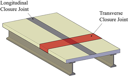
Figure 1. Schematic view of closure joints.
Closure Joint Types
Several closure joints are being used in ABC, as shown in Figure 2. Posttensioned closure joint utilizes female-to-female connections, and then longitudinal posttensioning is applied using either prestressing strands or high-strength steel bars, which are set through ducts inside the deck panels (Culmo, 2009; Aktan and Attanayake, 2013; Culmo et al., 2013). The splicing of ducts is achieved using duct tape or heat shrink wrap. Initially, the deck panels are placed as designed, and the closure joint is filled with grout. Next, the connection is achieved by posttensioning. The closure joint then is subjected to compression forces in transverse and longitudinal directions. This compressive force helps to mitigate tensile stresses. Although the posttensioning connection is advantageous in many aspects, it generally requires better quality control and a qualified contractor. As a consequence, the posttensioning connection may have a higher cost. Besides the cost, a lack of practical quality control during splicing and grouting may render the posttensioning ducts due to corrosion-related issues (Badie et al., 1999). Figure 2A shows a schematic detail for the posttensioned closure joint.
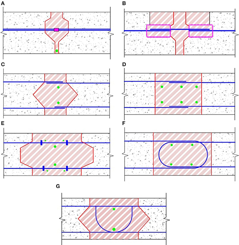
Figure 2. Schematic for common closure joints in ABC. (A) posttensioning, (B) mechanical connectors, (C) ultra-high performance with straight bars, (D) normal-strength concrete with straight bars, (E) normal-strength concrete with headed bars, (F) normal-strength concrete with 180° hooked bar, (G) normal-strength concrete with 90° hooked bar (recently developed).
Closure joints can be constructed using mechanical connectors. These joints use a welded or bar coupler; however, this connection is not popular because it is prone to corrosion, which causes long-term performance issues. The other option for this connection is the use of reinforcing dowels placed in slotted connection to splice the reinforcement from each side of the closure joint (Badie et al., 1999; Culmo, 2009; Aktan and Attanayake, 2013; Culmo et al., 2013), as shown schematically in Figure 2B.
Recently, many bridges were constructed using closure joints made of straight reinforcing bars with UHPC (Honarvar et al., 2016; Rallabhandhi, 2016; Semendary et al., 2017). UHPC is a cementitious composite material with very high compressive strength, high tensile strength, and excellent durability properties. UHPC can gain compressive strength of more than 22 ksi, as well as postcracking tensile strength >0.7 ksi (Russell et al., 2013) and excellent bond strength with normal-strength concrete substrates (Valikhani et al., 2020). Extensive experimental tests were conducted by Yuan and Graybeal (2014) to investigate the bond behavior of reinforcing steel in UHPC. Test results have indicated that UHPC can develop reinforcing bars in a very short length. The minimum embedment length of the reinforcing bar in UHPC can be eight times of the bar diameter (Saleem et al., 2013; Tazarv and Saiidi, 2015; Zhang and Graybeal, 2015). This short development length allows the reduction in closure joint width. Several projects were constructed using UHPC in closure joints by the New York State Department of Transportation (Graybeal, 2014). Using UHPC in closure joints makes the width of the connection smaller compared to NSC. However, the use of UHPC is associated with higher costs, therefore limiting its widespread use. Nevertheless, by the development of non-proprietary UHPC mixes and more usage of UHPC, it is expected that the cost will be reduced in the near future. Figure 2C shows the schematic detail for the closure joint made of UHPC and straight reinforcing bars. It should be noted that 180° hooked bars and headed bars are also being used in the field.
NSC is used in closure joints with different reinforcement details such as straight reinforcing bars (Culmo, 2009; Porter et al., 2012; Aktan and Attanayake, 2013; Culmo et al., 2013; LRFD Guide Specifications for Accelerated Bridge Construction, 2018) as shown in Figure 2D, headed bars as shown in Figure 2E (Culmo, 2009; Oesterle et al., 2009; Aktan and Attanayake, 2013; Culmo et al., 2013), 180° hooked bars as shown in Figure 2F (Culmo, 2009; Aktan and Attanayake, 2013; Culmo et al., 2013; LRFD Guide Specifications for Accelerated Bridge Construction, 2018), and 90° hooked bars, in laboratory environment, as shown in Figure 2G (Jahromi and Azizinamini, 2019). Wider closure joints are required when using NSC and spliced straight bars for tension development, which is not a preferred option due to concrete shrinkage (Abbas, 2011). Headed straight bars are also used with NSC to reduce the width of closure joints; however, several challenges associated with headed bars may render their use due to service life issues and higher unit cost. The primary concern is the concrete cover reduction due to the size of the head at the end of the bar, which reduces concrete cover at this location. The headed bars require careful detailing to avoid interfering with adjacent headed bars during placement precast deck panels. Full hooked bars (180° hooked bars) with NSC can offer economical and constructible details for closure joints. The full hook detail provides a solution to the clearance problem experienced with headed bars. However, few challenges with full hooked bars such as the use of the same bar size at the top and bottom of full-depth deck panels may lead to an overdesigned section and thicker deck (>9.5 in. instead of thickness typically <8.5 in.). New detail using 90° hooked bars with NSC was developed at Florida International University to overcome the drawbacks of closure joints with headed bars, straight bars, and 180° hooked bars (Jahromi and Azizinamini, 2019).
Service Life Design of Closure Joints
The service life design framework consists of identifying factors that can cause a reduction in the service life of any bridge element (closure joints, in this case) and provides strategies and approaches to mitigate them. The approaches to mitigate these factors could be more than one, resulting in the development of more than one final detail and alternative. The final selection could be made by consulting the agency standard practice or cost–benefit analysis (Azizinamini et al., 2014). The service life design framework uses a fault tree that provides a systematic approach for the service life design of any bridge element in general. Figure 3 shows a customized fault tree for closure joints. The service life design procedure leans itself toward automation using software. The procedure is meant for ensuring that all job requirements and restrictions are met for durability and service life. The extends of the fault tree depend on the nature of the bridge element being designed for service life.
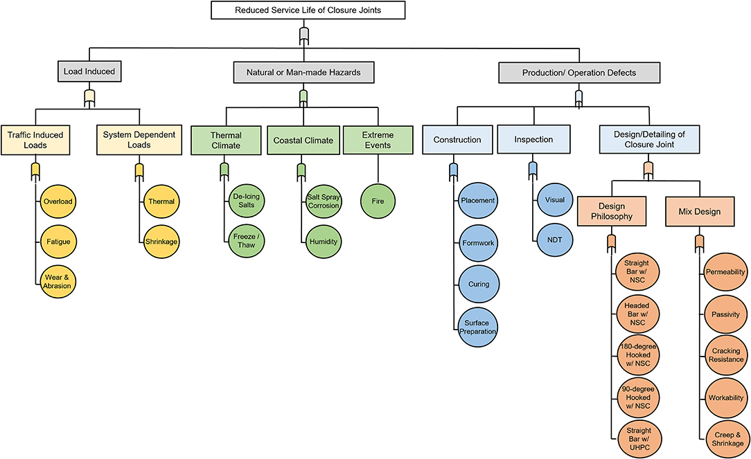
Figure 3. Reduced service life fault tree of closure joints.
The fault tree starts with the identification of major categories of factors that can reduce the service life of a particular bridge element, component, or subsystem. Each major factor can then be broken down into more detailed subcomponents. The fault tree continues branching until each branch ends with a factor, the lowest or base levels of influence. The factors with subcomponents are placed inside rectangles; however, the lowest or base factors are placed inside circles. The rectangles with a gray background in Figure 3, for example, show a portion of the fault tree used in service life design of closure joints. Either of the three main factors, shown in the second level, is capable of reducing the service life of closure joints. The elliptical symbol just above these three factors is referred to as a “gate,” which signifies that either one of the factors below could result in reduced service life. As an example in Figure 3, the “traffic-induced loads” are placed in a rectangle and may reduce the service life of closure joints. The “traffic-induced loads” are divided into three categories, each capable of reducing the service life of closure joints through different mechanisms. These factors are “overload,” “fatigue,” and “wear and abrasion.” One or more strategies are needed to mitigate every factor placed in each circle.
In the case of closure joints, the design for service life can follow after the design for strength according to the AASHTO-LRFD Bridge Design Specification (AASHTO LRFD, 2014) is completed. The design for service life proceeds by considering all mitigation strategies that can be used for addressing the base factors identified in the circles in Figure 3.
Factors Affecting Service Life of Closure Joints
Bridge deck closure joints are critical components within a typical bridge deck system. The reduced service life of closure joints can be attributed to three main causes: load-induced, manmade, and natural hazards, and result from product defects in construction processes and/or operational procedures, as shown in Figure 3 in boxes with a gray background.
Load Induced
Load-induced closure joint deterioration can be attributed to (1) loads induced by traffic (Caprani, 2013) such as overload, fatigue, and wear and abrasion, and (2) system-dependent loads such as shrinkage and thermal. These factors are introduced in the first branch of the fault tree, as shown in Figure 3.
The first identified factor from “traffic-induced load” is “overload.” Despite weight limit regulations in most US states that define load limits for permit truck and legal truck configurations, overloads exceeding these limits do occur. This is one of the main reasons for reducing the service life of bridges in general and specifically closure joints. Overloads result in additional flexural stresses in closure joints that can cause excessive cracking, which is not accommodated in the original design.
The second identified factor from “traffic-induced load” is “fatigue” (Su et al., 2016). Cast-in-place closure joints, which consist of steel reinforcement and concrete, are prone to fatigue due to the variation in live loads. Both materials fail in high-cycle fatigue.
The third identified factor from “traffic-induced load” is “wear and abrasion” (Ulloa Calderon, 2009). Wear and abrasion are typically affected by high traffic volume, high tire loads, and the types of tires used on the bridge. Tires in cold climates may have enhanced features to aid in traction, such as deep grooves, studs, and chains. These added tire features, while aiding traction, can abrade the surface of the closure joint. Wear and abrasion reduce the thickness of the bridge deck, which in turn reduces the concrete cover protecting the reinforcement from corrosion and reduces the load resisting section, resulting in higher stresses and cracking.
The first identified factor from “system-dependent loads” is “thermal” (Moorty and Roeder, 1992; Kim and Laman, 2010). Temperature changes can develop axial forces in the bridge deck; however, the effects on closure joints should be analyzed in consideration of the deck configuration and joint design. These thermal forces are due to uniform internal temperature changes and temperature gradient.
The second identified factor from “system-dependent loads” is “shrinkage” (Tia et al., 2005; Guo et al., 2011). Shrinkage occurs when fresh concrete is cast over previously cured concrete or steel girders. The shrinkage of fresh concrete is restrained by the cured concrete or steel stringers resulting in a set of equal and opposite forces, causing tension in the new concrete. The heat of hydration also can contribute to the development of tensile forces in the freshly cast concrete. In closure joints, the fresh is restrained by the adjacent hardened concrete. The restraint from precast deck panels can result in the formation of longitudinal cracks along the length and the interface of the closure joints. In addition, transverse cracks at some intervals along the length of the closure joint can also be developed.
Natural or Manmade Hazards
The environment to which the closure joint is subjected can have a significant influence on their service life. These environmental influences include hazards from both natural and manmade sources (Radic et al., 2003; Seible et al., 2008) and include effects from areas with adverse thermal climates and coastal climates, as well as from chemical properties of materials and outside agents such as a fire. These natural and manmade hazards are introduced in the second branch of the fault tree provided in Figure 3.
The first identified factor from “thermal climate” is “deicing salts,” which are a manmade hazard. Bridge agencies in cold weather climates have traditionally applied deicing salts to melt the ice and snow to facilitate tire traction on roadway and bridges. The application of these deicing salts is viewed as a safety enhancement for the traveling public; however, these chloride-laden compounds tend to ingress into the closure joint either through porosity in the concrete or through open deck cracks, within the closure joints. The chloride ingress into the closure joint continues to reduce the effectiveness of the passivating layer around the reinforcing steel, eventually initiating reinforcement corrosion. The reinforcement corrosion process causes reinforcing bars to expand, resulting in closure joint cracking, spalling, and/or delamination (Roelfstra et al., 2004).
The second identified factor from “thermal climate” is “freeze/thaw,” which is a natural hazard (Powers, 1975). Water absorbed into the closure joint surface and contained in cracks can freeze in cold weather conditions. The frozen water tends to expand, causing stresses within the concrete in bridge deck including closure joints. Cyclic freezing and thawing of the water absorbed in the deck surface can result in deterioration in the form of cracking, scaling, and spalling.
The first identified factor from “coastal climate” is “salt spray,” which is a natural hazard (Wright et al., 2012). Coastal regions are subjected to a chloride-laden saltwater environment and a combination of wind and wave action that causes these chlorides to become airborne as salt spray. The susceptibility of the closure joint to these environmental influences depends on the height of the bridge deck above the water elevation and the distance to coastal areas. The action of waves hitting substructure units and seawalls or abutments under the bridge tends to cause the salt spray to explode upwards, wetting the bottoms of lower-level bridge decks. The salt spray can also deposit itself on the bridge deck surface, particularly during windy days. When the salt spray wets the surfaces, it induces chloride residual that can be absorbed into the concrete, resulting in reinforcement corrosion. Salt spray can also take place by traveling jet skis below the bridge or towed by a car over the bridge without cleaning.
The second identified factor from “coastal climate” is “humidity,” which is a natural hazard. High humidity in coastal regions also results in cyclical wetting and drying of concrete surfaces. Concrete materials sensitive to repeated wetting, such as those where reactive aggregates are utilized, can adversely affect the closure joint service life.
One factor identified from “extreme events” is “fire” (Bennetts and Moinuddin, 2009; Peris-Sayol et al., 2017). In the case of fire, a key factor in the amount of damage that is caused to concrete, including that in the closure joints, is the duration of the fire and the heat levels generated. Because of the low thermal conductivity of concrete, it takes a considerable amount of time for the interior of concrete to reach damaging temperatures. When concrete is exposed to the extreme heat of a fire, the chemical bonds between the water molecules in the concrete break, resulting in dehydration, and destruction of the cement binder. Concrete loses its mechanical properties, exhibiting cracking and spalling, and exposes steel, leaving it unprotected (ACI 216R-89, 1994). Reinforcing steel in bridge decks subjected to temperatures above 550°C (1,022°F) exhibits a rapid reduction of strength, which can lead to collapse. In addition, spalling can result from the rapid quenching of hot fires by fire hoses.
Production and Operation Defects
Decisions made for the design and construction of closure joints and the activities that would occur during its operation can have a significant influence on their service life. These influences are introduced in the third branch of the fault tree provided in Figure 3 and include decisions made during the design and detailing of the closure joint, the quality of construction, the level of inspection, and the testing performed during operations and maintenance.
Construction
Attention to good practices during construction is crucial to the long-term durability of reinforced concrete. A workforce that is well-qualified and well-trained, and work that is well-executed, increase productivity, reduce material waste, and provide expected service life. The correct implementation of test methods ensures quality concrete. The construction issues are more pronounced when using higher quality cementitious materials such as UHPC.
The first identified factor from “construction” is “placement”. Good construction practices, which ensure the proper location of reinforcing steel for proper cover depth and consolidation curing, are essential for longevity. Proper consolidation minimizes entrapped air voids that can reduce strength and durability. The handling of concrete affects the final product. Delay in placement, particularly during hot days, should be avoided, as it can lead to stiffening of the concrete that can cause tearing of the deck surface during finishing, resulting in a poor surface finish and reduced durability.
The second identified factor from “construction” is “formwork”. The type of concrete formwork can affect the surface finish of the concrete. Impermeable forms can allow surface voids to occur, resulting in increased surface permeability, reduced strength, and an overall decrease in durability.
The third identified factor from “construction” is “curing”. Proper curing is necessary for the formation of the binder and the control of volumetric changes and includes both moisture and temperature control. In bridge structures, the closure joint surfaces require special attention due to their surface areas where the loss of moisture is a concern.
The fourth identified factor from “construction” is “surface preparation”. Connections between structural elements require special considerations to achieve a composite action, and closure joints are no exception to such detailing. Besides durability and waterproofing, the joints should have sufficient shear friction to prevent loss of composite action (Buyukozturk et al., 1990). Surface preparation is the most commonly used technique, which engages the inherent characteristic of concrete to furnish a rough interface. This roughness can be achieved using raking, water jetting, sand blasting, chipping, etc. The method of surface preparation depends on several factors including the substrate condition, properties of closure materials, the difference in age and modulus of elasticity of the materials, coating on reinforcing bars, etc. Depending on the joint, several protocols are necessary during preparation, cleaning, and application and are recommended to achieve a durable structural joint. Graybeal (2014) provides the best approaches for surface preparation of hardened concrete within a closure joint, which consist of the use of admixtures on the formwork when constructing the deck on girders of the prefabricated beam deck modules, combined with light water blasting after the removal of the forms to achieve an exposed aggregate surface.
Inspection
The first identified factor from “inspection” is “visual inspection” (Estes and Frangopol, 2003). Visual inspection is the most common type of inspection of the closure joints. Often a deficiency is not easily detectable and may show only subtle signs that can easily be missed by cursory inspections or by inexperienced inspectors. Deficiencies can also be located below the undamaged surface or in inaccessible areas. The inability to see the deficiency leads to inadequate identification of repair methods, scope, and material selection and could cause a structural failure without visible signs, since surficial repairs may cover the damaged area.
The second identified factor from “inspection” is “nondestructive test.” A variety of non-destructive testing methods have been utilized for the evaluation of bridge concrete decks in general, which include impact echo testing, pulse velocity testing, impulse response testing, laser testing, and magnetic flux leakage testing (Azizinamini, 2017; Farhangdoust et al., 2018; Jahromi et al., 2018a,b).
Ease of inspection can be considered as a criterion in the discrimination between service life design alternative; however, since inspection procedures differ between transportation agencies, ease of inspection is not considered in the section Practical Implementation Example.
Design and detailing consideration for closure joints
Closure joints between adjacent superstructure elements or modular systems form an integral part of the bridge superstructure. Typically, these joints are designed to transfer shear and moment across the interface based on AASHTO LRFD (2014) and LRFD Guide Specifications for Accelerated Bridge Construction (2018) and if not properly designed and detailed, may lead to damages including cracking along the adjacent member interface. For the design of each type of closure joint details (e.g., headed bar, straight bar, and hooked bar with either NSC, or UHPC), the requirements for development and lap splice lengths should be satisfied. Several designs can be developed for closure joints as shown in Figure 2.
Many factors can affect the service life of closure joints, which are related to the concrete mix design. First is permeability; concrete is a durable material that largely depends on its ability to resist the infiltration of water and aggressive solutions. Concrete with high permeability provides less resistance to aggressive solutions or water penetrating the concrete and possibly causing expansive forces due to physical (freeze/thaw) or chemical (corrosion, ASR, sulfate attack) factors.
Second is the passivity around reinforcement; the loss of passivity of the outer layer of the reinforcing steel initiates a corrosion process that deteriorates the steel. This corrosion process begins by diffusing chloride ions to the depth of the reinforcing steel and/or carbonation reducing the pH of the concrete to the passivating layer surrounding the concrete. Chloride ion ingress is facilitated through cracks or porous concrete.
Third is crack resistance; the mix design can affect the extent of cracking for all cast-in-place closure joints (Du et al., 2007; Sprinkel et al., 2010; Udaipurwala et al., 2015; Hoomes et al., 2017). Mixtures with high water and paste content are prone to shrinkage cracks that occur over time. The use of large aggregate sizes and well-graded aggregates reduces the water and paste content and minimizes shrinkage. In fresh concrete, when the rate of evaporation exceeds the rate of bleeding, plastic shrinkage occurs. Concrete with low bleed water, stiff consistency, and low water/cement ratio is prone to plastic shrinkage cracking. Prevention of plastic shrinkage cracking depends on prompt, effective curing.
Fourth is workability; concrete mix designs shall include good quality aggregates and appropriate admixtures to facilitate construction. Mix designs with poor workability can cause uncontrolled field adjustments to the mix through the addition of water in the field, resulting in higher water/cement ratios and overvibration that can cause aggregate segregation. Proper workability must be ensured for the integrity of the mix design to provide concrete with the intended properties.
Fifth are creep and shrinkage properties of concrete mixes; they can affect the service life performance of closure joints.
Mitigation Strategies for Factors Service Life of Closure Joints
A well-defined strategy should be used to mitigate factors that affect the service life of closure joints. Most often, there is more than one approach to mitigate a given factor capable of reducing the service life of closure joints. In these cases, more than one final design for closure joints is expected. Cost–benefit analysis can then be used to select the most economical detail and design. Tables 1, 2 list the possible mitigation strategies along with the advantages and disadvantages for traffic-induced loads (fatigue, overload, and wear and abrasion), system-dependent loads (shrinkage), natural and manmade hazard including thermal climate (deicing salts and freeze/thaw), and costal climate (salt spray and humidity), and production/operation defects (design).
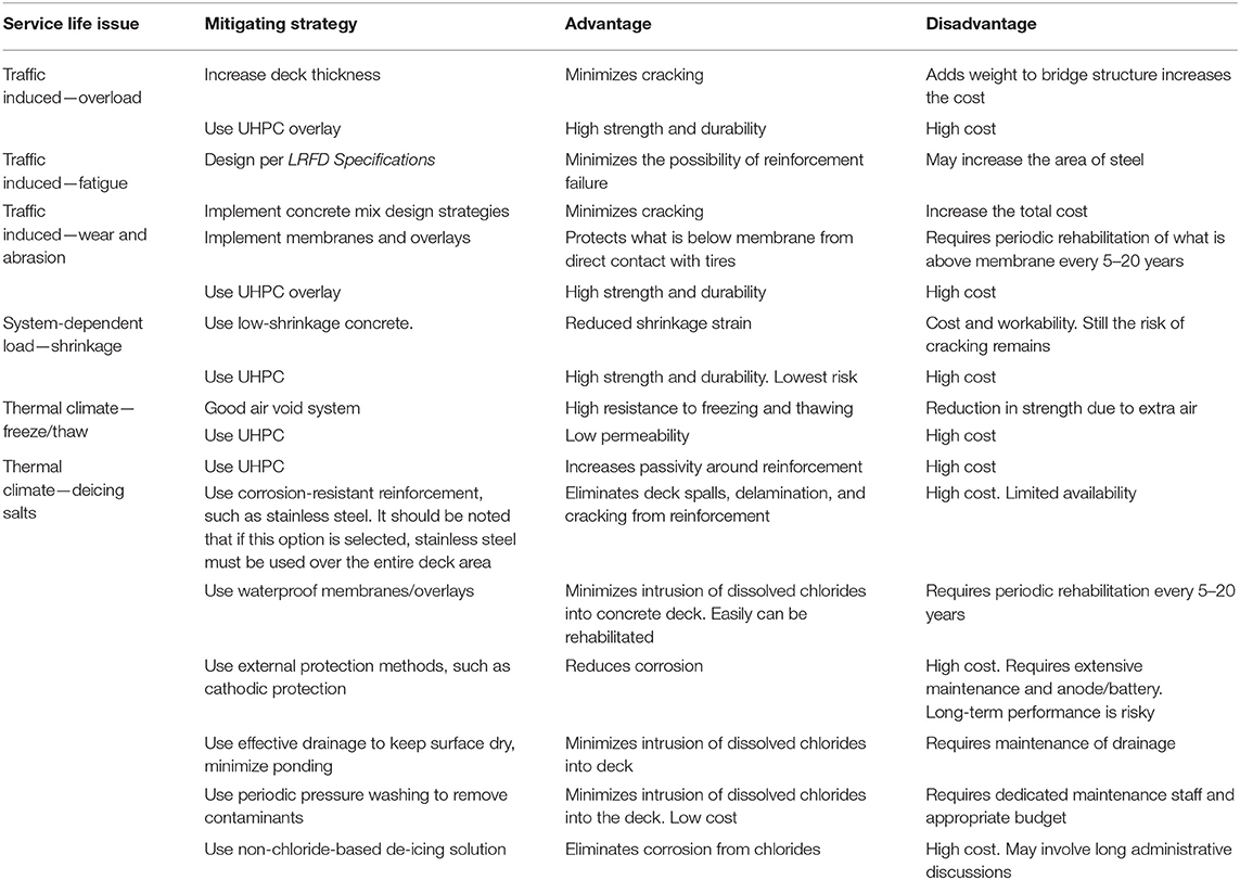
Table 1. List of individual strategies for mitigating load induced and thermal climate factors.
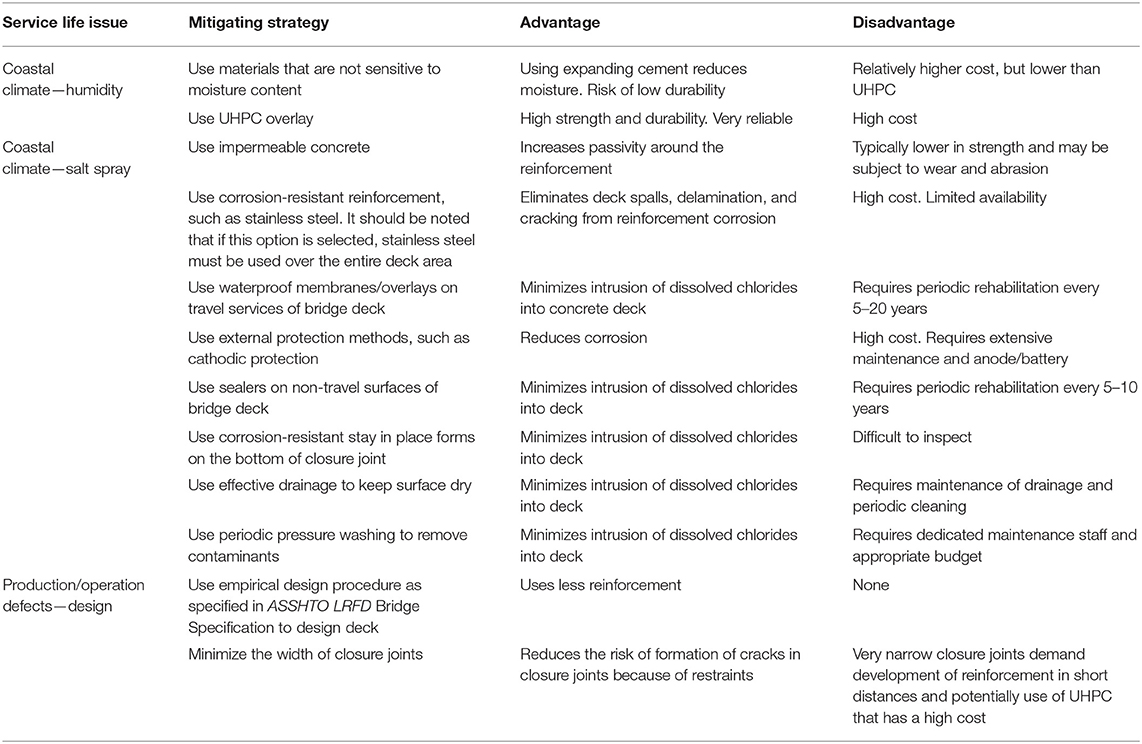
Table 2. List of individual strategies for mitigating coastal climate factors and production/operation defects.
As listed in Tables 1, 2, one mitigation strategy could address many factors that affect the service life of closure joints. For example, using waterproof membranes/overlays over the entire deck and closure joints can mitigate the effect of wear and abrasion, deicing salts, and salt spray. The use of UHPC overlay can mitigate the effect of overload trucks, wear and abrasion, deicing salts, and salt spray. The use of UHPC in closure joints can mitigate the effect of shrinkage, freeze/thaw, and design defects related to the width of closure joints.
Service Life Design Framework for Closure Joints
Framework for service life design of closure joints is provided in a flowchart format as shown in Figures 4, 5. This framework adopts the general procedure of American Society for Testing Materials International (2017); however, they are specific for bridge deck closure joints. The framework consists of 10 general steps as follows:
Step 1: Identification of bridge requirement, particularly those that influence the service life of closure joints (block 1a and block 1b)
Step 2: Identification of feasible closure joint types meeting project requirements (block 2)
Step 3: Selection of closure joint type and completion of service life steps
Step 4: Identification of factors affecting the service life of closure joints, such as traffic and environmental factors using fault tree as shown in Figure 3 (block 3–block 4)
Step 5: Identification of modes of failures and consequences (block 3)
Step 6: Identification of suitable mitigation strategies, using Tables 1, 2 (block 2A. a)
Step 7: Modification of closure joint alternatives (block 4)
Step 8: Estimation of the service life of each modified alternative (block 5)
Step 9: Comparison between the service life of closure joint alternatives and options (blocks 6, 7, 8)
Step 10: Conducting life cycle cost analysis, and selection of the optimum closure joint (blocks 7 and 9).
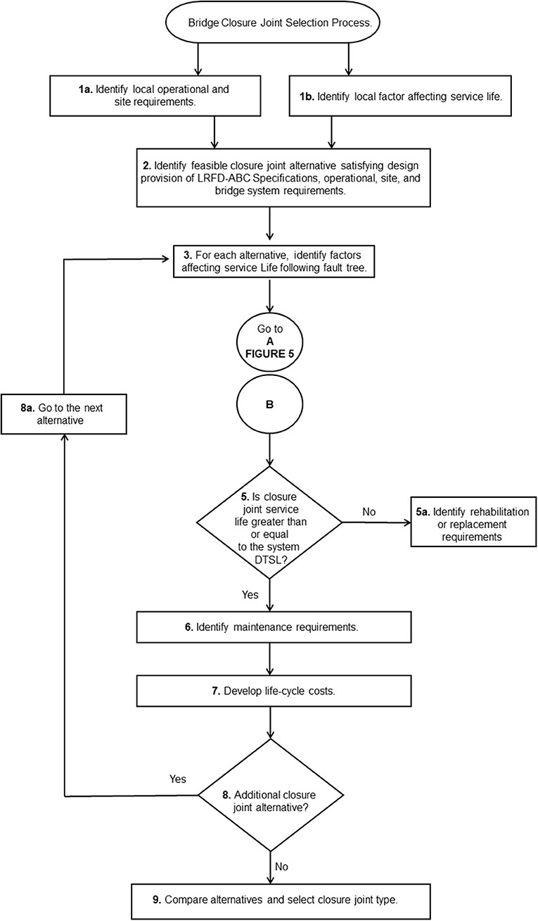
Figure 4. Bridge closure joint selection process.
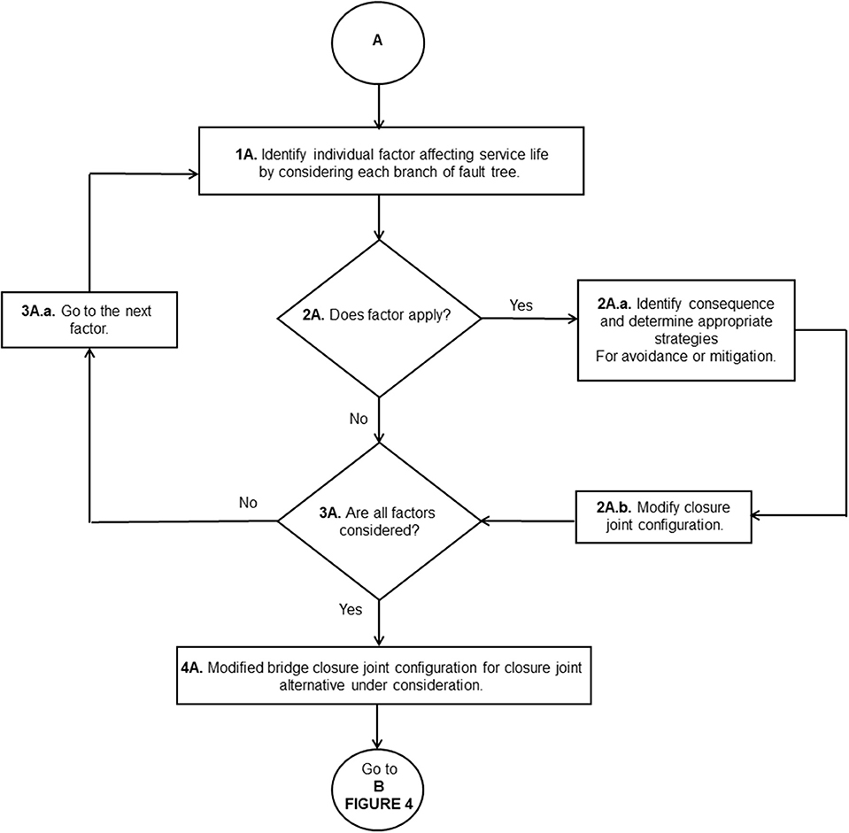
Figure 5. Bridge closure joint selection process (Cont).
Each step of the service life design framework is illustrated in the section Practical Implementation Example.
Practical Implementation Example
Service life design example using the 10 steps mentioned in Service Life Design Framework for Closure Joints is presented in this section. The example bridge is a 1,400-ft-long structure carrying four lanes of high volume traffic with pedestrian sidewalks and bicycle lanes in Boston, MA, United States. The bridge is constructed using prefabricated adjacent deck beam elements, consisting of steel box girders with full-depth deck cast on top, transported to its final site, and connected using longitudinal closure joints. The bridge is designed to utilize a simple for dead load and continuous for live load concept (Lampe et al., 2014; Yakel and Azizinamini, 2014; Sadeghnejad et al., 2019), which demands to have transverse closure joints. The bridge crosses over low-volume urban local roads, a railroad, and a navigable waterway. Figure 6 shows a rendering and elevation of the bridge. Figure 7 shows the cross-section of bridge superstructures, which is used for this example. Longitudinal closure joints, in traffic direction, are placed in between the two box sections. Each steel box with a pretop deck is cast near the job site; therefore, there is no width limitation for transportation. The width of closure joints could range from 3 ft. to 8 in. based on the type of reinforcement details and the material used in the closure joints.
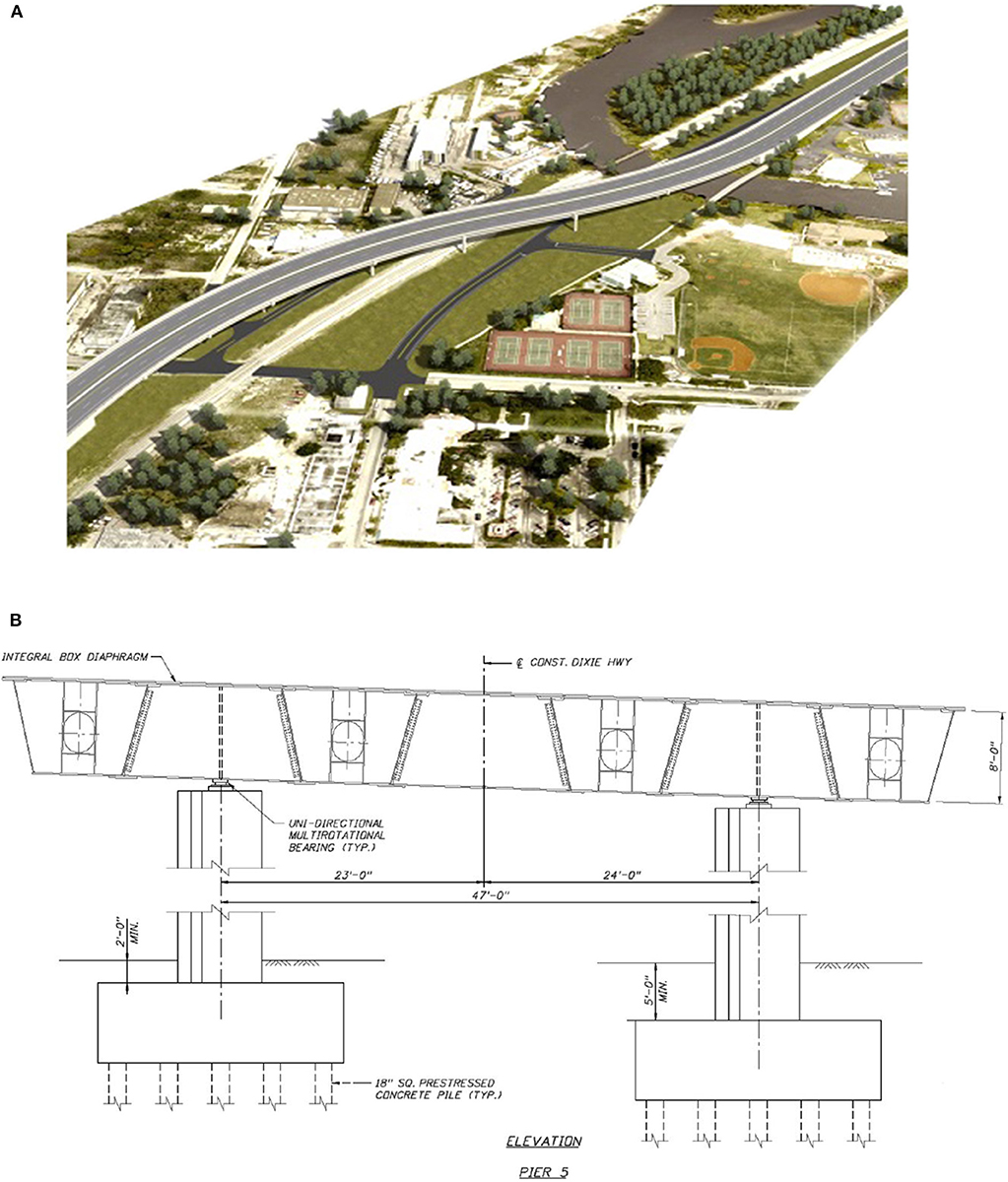
Figure 6. Typical superstructure/substructure configuration (A) rendering and (B) bridge elevation.
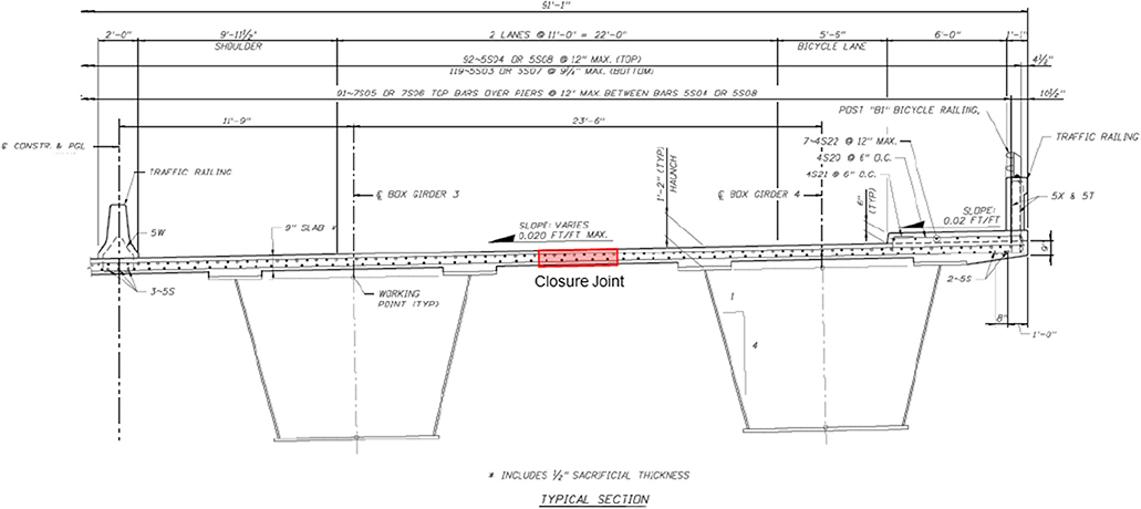
Figure 7. Superstructure cross-section.
Step 1: Identification of Bridge Requirements
The bridge settings include the following main characteristics, which influence the bridge service life:
1. The bridge is located in a cold environment where deicing salts are present, and multiple cycles of freeze/thaw are anticipated.
2. The bridge is located in an area where studded tires are used in the winter.
3. The bridge is subjected to potential overloads with 20-kip tire loads in an HL93 truck configuration.
4. The bridge spans over a navigable waterway with primarily brackish conditions and is located near a park with water access for jet skis.
5. The bridge is located near the coastline with possible saltwater storm surge with potential hurricane-force winds up.
6. The surface chloride concentration is 0.68% of concrete weight (16.32 kg/m3 or 1 lbs/ft3).
Step 2: Identification Feasible Closure Joint Types Meeting Project Requirements
NSC, UHPC, and PC show acceptable performance as a filler material in bridge deck closure joints; however, since NSC and UHPC are already implemented in bridge closure joints, both materials are selected to develop feasible alternatives. Straight bars, headed bars, 180° hooked bars, and 90° hooked bars are commercially used in bridge deck closure joint. These reinforcement details are selected to develop feasible alternatives since each reinforcement detail controls the design width of closure joints, therefore controlling the volume of the filler material. Black and stainless steels are also available, which have a difference in unit cost and corrosion resistance.
Five alternatives for closure joints are designed for strength limit state as follows:
1. Alternative 1: NSC and straight spliced bars, as shown in Figure 8A. The joint width for this alternative is 3 ft. according to LRFD Guide Specifications for Accelerated Bridge Construction (2018).
2. Alternative 2: NSC and 90° hooked bars, as shown in Figure 9A. The joint width for this alternative is 12 in. according to Jahromi and Azizinamini (2019).
3. Alternative 3: NSC and 180° hooked bars, as shown in Figure 10A. The joint width for this alternative is 18 in. according to LRFD Guide Specifications for Accelerated Bridge Construction (2018).
4. Alternative 4: NSC and headed bars, as shown in Figure 11A. The joint width for this alternative is 14 in. according to LRFD Guide Specifications for Accelerated Bridge Construction (2018).
5. Alternative 5: UHPC and straight spliced bars, as shown in Figure 12A. The joint width for this alternative is 8 in. according to Graybeal (2014).
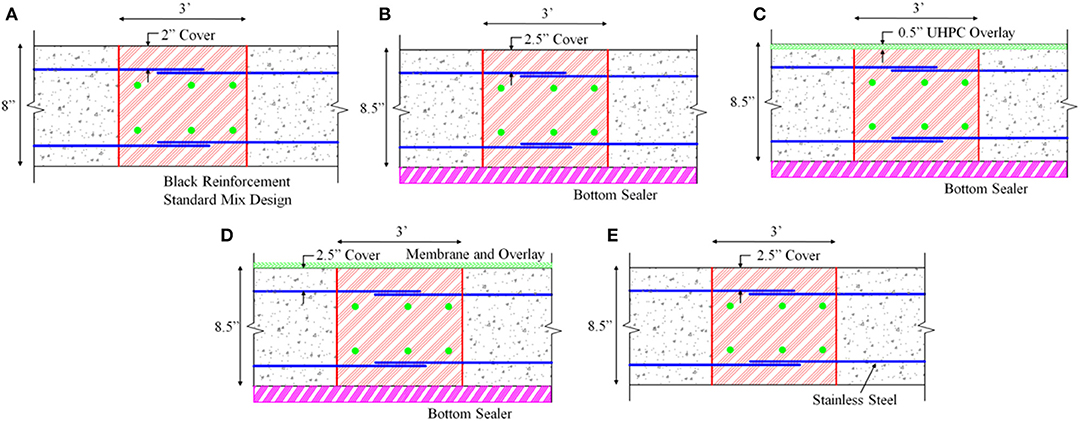
Figure 8. Closure joint Alternative 1, using NSC with straight bars (A) strength design, (B) Option 1, (C) Option 2, (D) Option 3, and (E) Option 4.
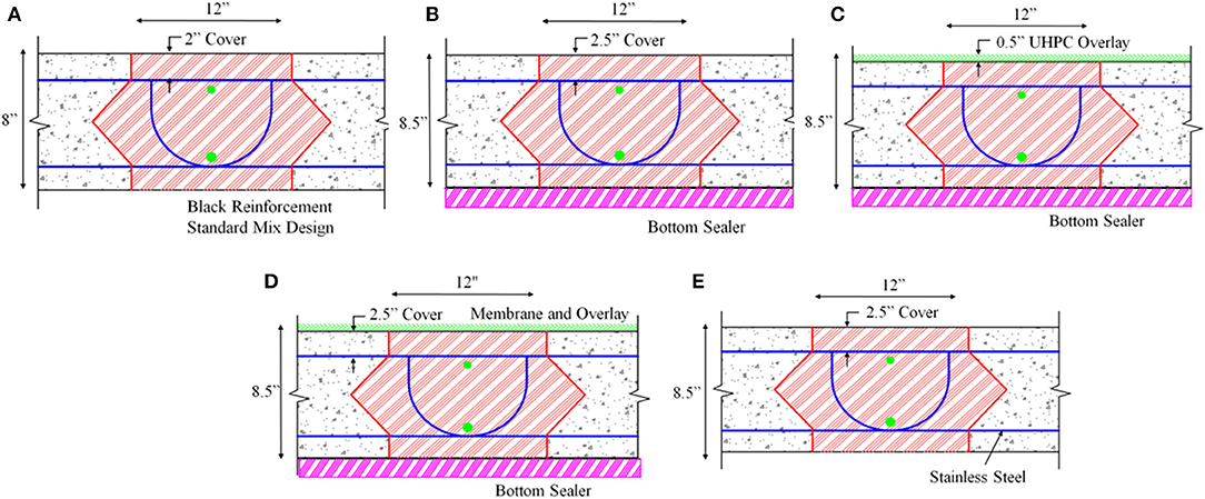
Figure 9. Closure joint Alternative 2, using NSC with 90° hooked bars (A) strength design, (B) Option 1, (C) Option 2, (D) Option 3, and (E) Option 4.
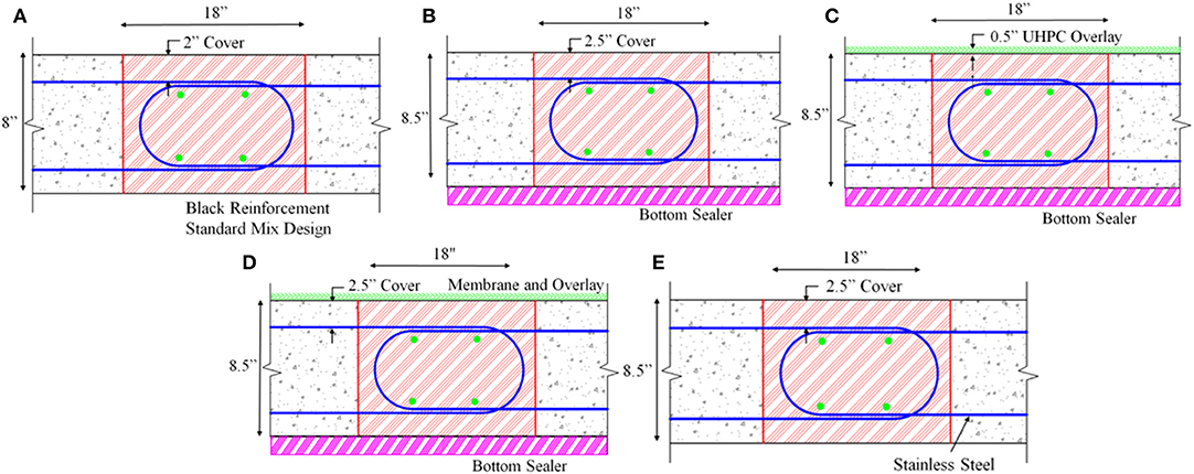
Figure 10. Closure joint Alternative 3, using NSC with 180° hooked bars (A) strength design, (B) Option 1, (C) Option 2, (D) Option 3, and (E) Option 4.
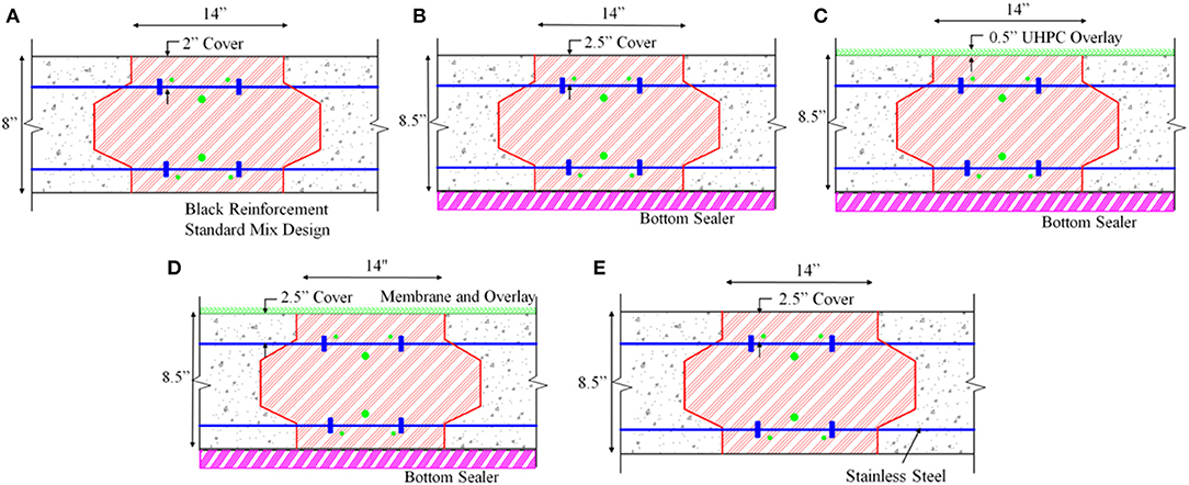
Figure 11. Closure joint Alternative 5, using NSC with headed bars (A) strength design, (B) Option 1, (C) Option 2, (D) Option 3, and (E) Option 4.
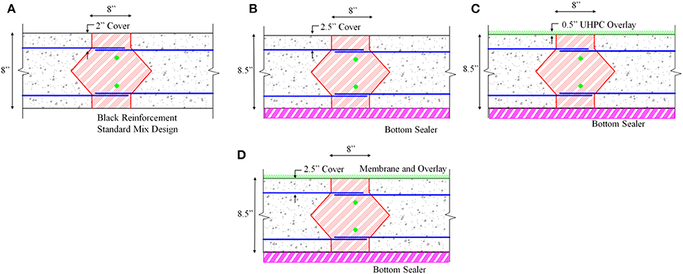
Figure 12. Closure joint Alternative 5, using UHPC with straight bars (A) strength design, (B) Option 1, (C) Option 2, and (D) Option 3.
Step 3: Selection of Closure Joint Type and Completion of Service Life Steps
Figures 4, 5 provide steps for completing the service life design of each feasible closure joint alternative and making the final selection. In the following sections, the service life design process is also related to corresponding blocks within flowcharts, for instances, blocks 1a and 2 are related to Steps 1 and 2.
Step 4: Identification of Factor Affecting the Service Life of Closure Joints
By consulting Factors Affecting Service Life of Closure Joints and Figure 3 and bridge requirement in Step 1, eight factors that affect the service life of each closure joint alternative are identified in this example including fatigue, overload, wear and abrasion, shrinkage, deicing, freeze/thaw, salt spray, and humidity. These factors should differ from a bridge to another based on project requirements and location. Production and operation defects along with fire (manmade hazard) are not selected in this practical example to avoid introducing numerous details that would distract the reader.
Step 5: Identification of Modes of Failures and Consequences
In this step, the designer is required to identify the modes of failures and consequences. For the closure joint, the leakage of moisture through longitudinal or transverse cracks in the closure joints can cause corrosion of reinforcement causing corrosion-induced cracking and loss of strength.
Step 6: Identification of Suitable Mitigation Strategies
By consulting Mitigation Strategies for Factors Service Life of Closure Joints and Tables 1, 2, individual strategies capable of mitigating the factors can be chosen. Table 3 lists suitable mitigation strategies for each identified factor from Step 4. Table 3 also lists the project requirements (from Step 1), which are associated with certain identified factors (from Step 4).
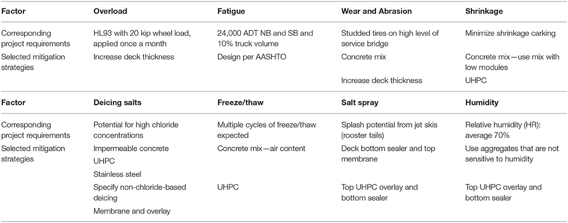
Table 3. List of strategies specific for developing closure joint alternatives and options for service life design of the practical implementation example.
Step 7: Modification of Closure Joint Alternatives
Considering the five alternatives under consideration (Step 2), factors that can reduce the service life of closure joints (Step 4), and strategies capable of mitigating factors, capable of reducing the service life of closure joints (Step 6), the following are possible solutions (options) that can meet the service life design objectives:
Option 1—Increasing the deck and closure joint thickness by 0.5 in. using NSC, and the use of bottom sealers, as shown in Part B in Figures 8–12 for Alternatives 1–5, respectively. This option is proposed to present the lowest initial cost.
Option 2—Increasing the deck and closure joint thickness by 0.5 in. using UHPC overlay and the use of bottom sealers, as shown in Part C in Figures 8–12 for Alternative 1–5, respectively. This option is proposed to present the lowest life cycle cost.
Option 3—Increasing the deck and closure joint thickness by 0.5 in. using NSC, and the use of membrane and asphalt overlay, and bottom sealers as shown in Part D in Figures 8–12 for Alternatives 1–5, respectively. This option is proposed to present the highest life cycle cost.
Option 4—Increasing the deck and closure joint thickness by 0.5 in. using NSC, and the use of stainless-steel reinforcement type 316 in closure joints and deck panels, as shown in Part E in Figures 8–11 for Alternatives 1–4, respectively. This option is proposed to present the highest initial cost. It should be noted that this option was not applied to closure joints made of UHPC due to the lack of design provision of stainless-steel reinforcement with UHPC for closure joints.
Table 4 provides a summary for each option for Alternatives 1–5, respectively, in addition to the initial cost of the closure joint and mitigation strategies as total initial cost and per square foot area of the deck, which is 1,400 ft. in length and 91 ft. in width. Table A1 provides a breakdown of the initial cost for each alternative–option.
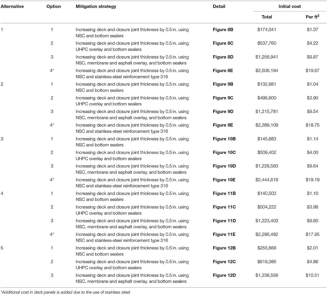
Table 4. Practical implementation example: alternatives, options, mitigation strategies, and initial cost.
The initial costs reported in Table 4 are based on the following material unit cost:
1. Cost of NSC at $150/yd3 (average unit cost of concrete by US consumers = $147/yd3);
2. Cost of sealer for sealing the bottom of the deck at $0.65/ft2 of the deck area (default unit cost in Life-365);
3. Cost of reinforcement is estimated using No. 5 reinforcing bars spaced at 12 in. at the center, on top and bottom layers, longitudinally, as shown in Figures 8–12. For black steel, the cost is assumed at $0.45/lb. For headed steel bars, the cost is assumed at $0.75/lb. For stainless steel, the cost is assumed at $3.00/lb (default unit cost in Life-365).
4. Cost of UHPC at $2,000/yd3 (average unit cost between propriety and non-propriety material by reaching out to manufactures);
5. Cost of membrane for the top surface at $7/ft2 of the bridge deck (default unit cost in Life-365);
6. Cost of asphalt overlay is assumed at $1.5/ft2 of the bridge deck (minimum cost of asphalt overlay in the United States); and
7. An additional initial cost is added to Option 4 in. all alternatives due to the use of stainless steel all over the deck area, which led to an increase in the prime of deck panels.
It should be noticed that the assumptions mentioned above may vary between the United States and worldwide. Bridge engineers are encouraged to be revised and modify those assumptions to fit specific project needs.
Step 8: Estimation of Service Life of Each Modified Alternative
When calculating the service life of the bridge deck for various options, an assumption is made that corrosion is initiated by chloride ingress through the deck and reaching the threshold value at the first layer of deck reinforcement. Furthermore, the repair takes place 6 years after the start of corrosion activities. The time to start the corrosion is calculated using Fick's second law and assuming one-dimensional ingress of chloride through the concrete deck. The error function solution to Fick's second law, for one-dimensional chloride ingress, is as follows:
where C(x, t) is the chloride concentration at depth x and time t, C0 is the surface chloride concentration (kg/m3 or lb/yd3), Dc is the chloride diffusion constant (cm2/year or in2/year); and erf is the error function (from standard mathematical tables).
Equation 1 can be used to assess the ingress of chloride through the concrete cover. As an example, Figure 13 indicates the type of information that can be developed, which shows chloride concentration through the deck thickness for three periods, after a deck is cast. The information shown in Figure 13 can be used to predict the time when corrosion starts to be initiated, which in turn can be used to estimate the service life of the bridge deck if corrosion of reinforcement is the main mode of deterioration.
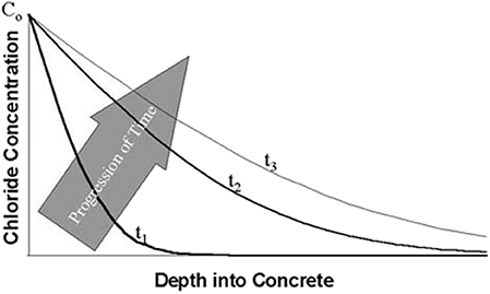
Figure 13. Chloride concentration within concrete over time.
To complete this example, Life-365, a free program developed by the concrete admixture industry, is used to conduct the life cycle cost analysis and assist in selecting an optimum solution. Life-365 uses a finite-difference approach to solve Fick's second law and to estimate the time to initiation of corrosion. Other approaches, such as error function solution to Fick's second law, Equation 1, could also be used.
The solution to Fick's second law estimates the time to initiation of corrosion, ti. For example, it is assumed (assumption within Life-365) that once the corrosion is initiated, the time to propagate the corrosion to the point at which repair is needed, tr, is a constant 6 years, regardless of the concrete mix used. Following the period ti + tr, Life-365 assumes repair action at set time intervals, say every 10 or 20 years, and set the cost per square feet of the deck. Furthermore, within each repair cycle, it is assumed that only a portion of the deck area needs to be repaired. For this example, the assumption is made that the repair area is equal to the area of the closure joints.
The time to initiate corrosion depends on the concrete mix and preventive measures, such as the use of stainless steel, concrete cover, or membranes. Life-365 follows the guidance and terminology in ASTM E-917 (American Society for Testing Materials International, 2017). The final number that can be used to select the optimal deck alternative can be the life cycle cost, which is the initial cost plus the present value of all future rehabilitation costs over the desired service life; in this case, 100 years is assumed.
Table 5 shows the general input parameters used within Life-365 to conduct a life cycle cost analysis for all alternatives and options. Table 5 also shows the yearly temperature profile used. The diffusion coefficient and ingress of chloride are influenced by temperature fluctuation. Table 6 lists the specific input parameters that vary from option to option.
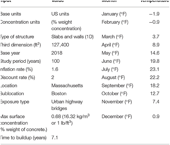
Table 5. Input parameters in Life-365 for all five alternatives.
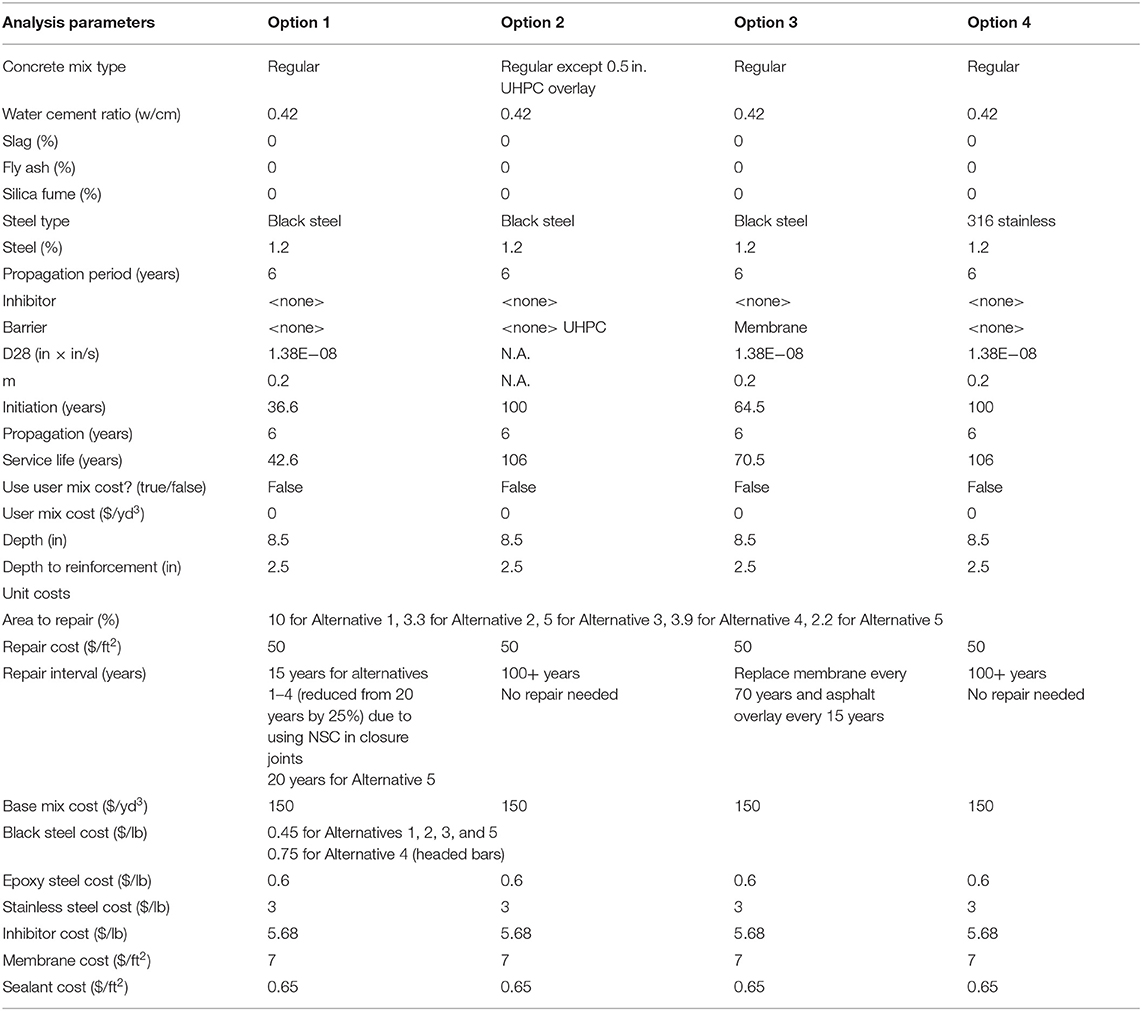
Table 6. Parameters in Life-365 specific to each alternative and option.
The following assumptions were used to consider the effect of the closure joint on the estimation of the deck service life:
1. The service life for a specific option was calculated using Life-365 except for Option 2 (using 0.5 in. of UHPC overlay and bottom sealers). The service life of Option 2 was found to be over 100 years due to the durability and low chloride intervention through UHPC (Farzad, 2019) with chloride concentration up to 30 kg/m3 (1.84 lbs/ft3) and the lack of UHPC overlays in Life-365.
2. Start time for repair and its interval as follows:
• Repair starts after 6 years of chloride at the first layer of reinforcement in the deck reaches the threshold value. The time to reach the chloride threshold value at the first layer of reinforcement in the deck is calculated using Life-365.
• Repair interval is assumed to be every 20 years after corrosion has propagated to the critical value (in this example, it is assumed that the critical time is 6 years after chloride at the first layer of reinforcement reaches the threshold value). This 20-year repair time interval is reduced to 15 years when any material other than UHPC is used in the closure joint.
3. Repair area is assumed to be equal to the total area of closure joints. It should be noted that this assumption is to arrive at the percentage of the deck area that needs repair and does not necessarily indicate that all closure areas should be repaired.
4. When using a membrane on the top of the deck, replacement of asphalt overlay is required every 15 years.
5. The repair cost of concrete decks is assumed to be $50/ft2 area of the repair region (Azizinamini et al., 2014).
Table 7 lists the service life prediction and repair intervals for each alternative–option.
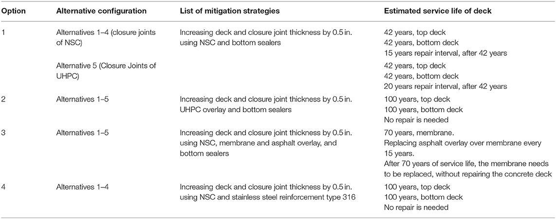
Table 7. Estimated service life and repair interval for each alternative and option.
Step 9: Comparison Between Service Life of Closure Joints Alternative and Options
The service life of option 1 for Alternatives 1–5 was estimated from Life-365 to be 42 years with repair interval of 20 years if UHPC is the material of the closure joint (Alternative 5) and 15 years if other than UHPC was used in the closure joints (Alternatives 1–4). For Option 2 for Alternatives 1–5, the service life of the deck was found to be over 100 years due to the use of UHPC overlay and bottom sealers. For Option 3 for Alternatives 1–5, the service life was estimated to be 70 years from Life-365; therefore, the top membrane shall be replaced one time during the life of the bridge in addition to the replacement of asphalt overlay every 15 years. For Option 4 for Alternatives 1–4, the service life was estimated to be more than 100 years from Life-365 due to the use of stainless steel in the closure joint and bridge panels. The summary of the service life of each option is presented in Tables 6, 7.
Step 10: Conducting Life Cycle Cost Analysis and Selection of the Optimum Closure Joint
In this example, only the final life cycle cost is presented. The development of maintenance and operation depends on individual practices in each state and agency and is not included in this example. The following is a summary of the life cycle cost study of alternatives considered, which should provide ample information for a designer and an owner to select the final closure joint detail that meets both strength and service life design requirements.
Table 8 lists the initial cost (cost of closure joints and mitigation strategies) and the life cycle cost (initial cost plus repair cost) for all alternatives and options. For option 1, the life cycle cost was estimated from Life-365. For Options 2 and 4 for all alternatives, the service life of the deck was estimated to be higher than 100 years; therefore, no repair cost is required, which led to a match between the initial cost and the life cycle cost. For Option 3 for all alternatives, the repair cost was estimated manually by adding the cost of one membrane replacement and six asphalt overlay (assumption was made that asphalt overlay over the membrane should be replaced, once every 15 years) replacements by neglecting the inflation in repair cost over 100 years.
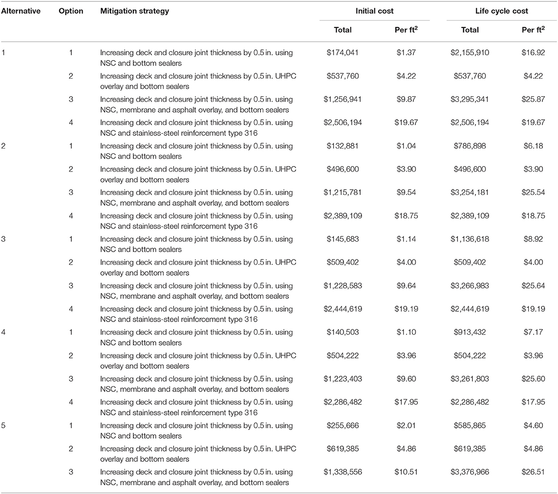
Table 8. Life cycle cost analysis for alternative–option.
It can be noted that the use of 0.5 in. of UHPC overlay and bottom sealer (Option 2) yields the lowest life cycle cost compared to other options. The use of 0.5 in. of NSC overlay and bottom sealer (Option 1) yields the lowest initial cost compared to other options; however, the life cycle cost was estimated to be much higher than the initial cost for this option. The use of 0.5 in. of NSC overlay and stainless steel (Option 4) yields the highest initial cost without any need for repair.
Summary and Conclusions
The use of prefabricated bridge superstructure elements is one of the most used ABC techniques. For superstructure, full-depth precast deck panels or modular units are connected together in-suit using closure joints. The design for the strength limit state for the bridge deck closure joint is straightforward; however, this approach does not consider the in-service factors that deteriorate the performance of closure joints, likewise any other bridge elements. In general, the design for service life is approached by utilizing individual strategies, each capable of enhancing the service life of a particular bridge element; however, the design for service life should be conducted in a systematic manner using a framework that is generic and applicable for all bridges, while having differences from one bridge to another. This paper proposes a framework or procedure to design for service life for bridge deck closure joints that includes complete information about factors affecting the service life of bridge deck closure joints such as load-induced, natural, and manmade hazards, and production and operation defects, in addition to a list of mitigation strategies that is provided to address each factor. This proposed framework was then implemented in a practical bridge example for different types of closure joints, which utilize different types of concrete (NSC and UHPC), different reinforcement details (straight bars, 180° hooked bars, 90° hooked bars, and headed bars), and different types of reinforcement (black and stainless steels). Factors affecting the service life of closure joints of a bridge in coastal areas, which are also prone to thermal climate, are identified and studied. Then, different mitigation strategies were deployed to address those factors. A set of alternatives (closure joints details) along with options (mitigation details) are developed and compared to each other in terms of service life, repair intervals, and life cycle cost analysis.
The following conclusions and findings can be drawn based on this study:
• A framework that addresses factors affecting the service life of closure joints and proposes mitigation strategies is developed and should be used to comprehend the service life design of closure joints. In addition, the developed framework is systematic and user-friendly.
• The location of the target bridge, in which closure joints are meant to be designed for service life, affects the design for service life procedure. For example, bridges located far away from a coastal area are not affected by humidity or salt spray, whereas bridges in a thermal climate area are prone to deicing salts and freeze/thaw.
• One mitigation strategy can address multiple factors affecting the service life of closure joints. For example, using waterproof membranes/overlays over the entire deck or over closure joints can mitigate the effect of wear and abrasion, deicing salts, and salt spray; the use of UHPC overlay can mitigate the effect of overload, wear and abrasion, deicing salts, and salt spray; and the use of UHPC in closure joints can mitigate the effect of shrinkage, freeze/thaw, and design defects related to the width of closure joints.
• The use of UHPC in closure joints can reduce the repair intervals (increasing the period needed for repair) due to the high resistance of this material to chloride intrusion.
• The use of overlay made of UHPC and bottom deck sealers provided the most economical life cycle cost if compared to overlay made of NSC and bottom sealer; the use of membrane, asphalt overlay, and bottom deck sealer; and the use of overlay made of NSC and stainless steel over the entire deck despite its high initial cost.
• Although the option of overlay made on NSC and bottom deck sealer presents the most economical initial cost for closure joint and mitigation strategies, it results in high life cycle cost due to the increased number of repair intervals.
Author's Note
This manuscript adopts the general framework presented in a Pre-Print at http://onlinepubs.trb.org/onlinepubs/shrp2/SHRP2prepubR19AGuide.pdf.
Author Contributions
AA conceived the project. AJ, AV, and AA developed the guidelines. IM and AA developed the practical implementation example. IM and AJ wrote the manuscript. All authors read and approved the manuscript.
Funding
This project was funded by USDOT through Accelerated Bridge Construction University Transportation Center (ABC-UTC) at Florida International University, Grant Number DTRT13-G-UTC41 (2013).
Conflict of Interest
The authors declare that the research was conducted in the absence of any commercial or financial relationships that could be construed as a potential conflict of interest.
References
AASHTO LRFD (2014). AASHTO LRFD Bridge Design Specifications, 7nth Edn, 2014, U.S. Customary Units: 2015 interim revisions; American Association of State Highway and Transportation Officials (2014).
Abbas, E. K. (2011). Corrosion Assessment for Failed Bridge Deck Closure Pour. Doctoral dissertation, Virginia Tech.
ACI 216R-89 (1994). ACI Committee 216 Guide for Determining the Fire Endurance of Concrete Elements. Farmington Hills, MI: American Concrete Institute, 198.
Aktan, H., and Attanayake, U. (2013). Improving Bridges With Prefabricated Precast Concrete Systems (No. RC-1602). Lansing, MI: Dept. of Transportation; Office of Research Administration.
American Society for Testing and Materials International (2017). Standard Practice for Measuring Life-Cycle Costs of Buildings and Building Systems. West Conshohocken, PA: ASTM.
Azizinamini, A. (2017). Non-destructive testing (NDT) of a segmental concrete bridge scheduled for demolition, with a focus on condition assessment and corrosion detection of internal tendons. Available online at: https://pdfs.semanticscholar.org/8715/9ffb19a5bb568e3d1bdebd27f3d50fb16311.pdf?_ga=2.53731435.2127469767.1582189628-1400675960.1576841025
Azizinamini, A., Power, E. H., Myers, G. F., Ozyildirim, H. C., Kline, E. S., Whitmore, D. W., et al. (2014). Design Guide for Bridges for Service Life (No. SHRP 2 Report S2-R19A-RW-2).
Badie, S. S., Kamel, M. R., and Tadros, M. K. (1999). Precast pretensioned trapezoidal box beam for short span bridges. PCI J. 44, 48–59. doi: 10.15554/pcij.01011999.48.59
Badie, S. S., and Tadros, M. K. (2008). Full-Depth Precast Concrete Bridge Deck Panel Systems, Vol. 584. Washington, DC: Transportation Research Board.
Bennetts, I., and Moinuddin, K. (2009). Evaluation of the impact of potential fire scenarios on structural elements of a cable-stayed bridge. J. Fire Protect. Eng. 19, 85–106. doi: 10.1177/1042391508095091
Buyukozturk, O., Bakhoum, M. M., and Michael Beattie, S. (1990). Shear behavior of joints in precast concrete segmental bridges. J. Struct. Eng. 116, 3380–3401. doi: 10.1061/(ASCE)0733-9445(1990)116:12(3380)
Caprani, C. C. (2013). Lifetime highway bridge traffic load effect from a combination of traffic states allowing for dynamic amplification. J. Bridge Eng. 18, 901–909. doi: 10.1061/(ASCE)BE.1943-5592.0000427
Culmo, M. P. (2009). Connection Details for Prefabricated Bridge Elements and Systems (No. FHWA-IF-09-010). Federal Highway Administration; Office of Bridge Technology.
Culmo, M. P., Boyle, H., Nettleton, S., Chandra, V., Tadros, M. K., and Mallela, J. (2013). Engineering Design, Fabrication and Erection of Prefabricated Bridge Elements and Systems (No. FHWA-HIF-17-019). Federal Highway Administration.
Culmo, M. P., Lord, B., Huie, M., and Beerman, B. (2011). Accelerated Bridge Construction: Experience in Design, Fabrication and Erection of Prefabricated Bridge Elements and Systems: Final Manual (No. FHWA-HIF-12-013). Federal Highway Administration; Office of Bridge Technology.
Du, Y., Clark, L. A., and Chan, A. H. (2007). Impact of reinforcement corrosion on ductile behavior of reinforced concrete beams. ACI Struct. J. 104:285. doi: 10.14359/18618
Estes, A. C., and Frangopol, D. M. (2003). Updating bridge reliability based on bridge management systems visual inspection results. J. Bridge Eng. 8, 374–382. doi: 10.1061/(ASCE)1084-0702(2003)8:6(374)
Farhangdoust, S., Mehrabi, A. B., and Mowsavi, S. F. A. (2018). “NDT methods applicable to health monitoring of ABC closure joints,” in 27th Research Symposium-The American Society for Non-destructive Testing (ASNT) (Orlando, Fl), 26–29.
Farzad, M. (2019). Retrofitting of bridge elements subjected to predominantly axial load using uhpc shell. Ph. D. dissertation, Florida International University, Miami, FL, United States.
Graybeal, B. (2014). Design and Construction of Field-Cast UHPC Connections (No. FHWA-HRT-14-084; HRDI-40/10-14 (750) E). Federal Highway Administration.
Graybeal, B. A. (2010). “Behavior of Ultra-High Performance Concrete connections between precast bridge deck elements,” in Proceedings of the 2010 Concrete Bridge Conference: Achieving Safe, Vol. 24 (Phoenix, AZ: Smart and Sustainable Bridges).
Gull, J. H., Yakel, A., and Azizinamini, A. (2014). Experimental Investigation of Longitudinal Closure Pour Detail for Prefabricated Slabs Used in Modular Construction (No. 14–1211).
Guo, T., Sause, R., Frangopol, D. M., and Li, A. (2011). Time-dependent reliability of PSC box-girder bridge considering creep, shrinkage, and corrosion. J. Bridge Eng. 16, 29–43. doi: 10.1061/(ASCE)BE.1943-5592.0000135
Honarvar, E., Sritharan, S., Matthews Rouse, J., and Aaleti, S. (2016). Bridge decks with precast UHPC waffle panels: a field evaluation and design optimization. J. Bridge Eng. 21:04015030. doi: 10.1061/(ASCE)BE.1943-5592.0000775
Hoomes, L. C., Ozyildirim, H. C., and Brown, M. (2017). Evaluation of High-Performance Fiber-Reinforced Concrete for Bridge Deck Connections, Closure Pours, and Joints (No. FHWA/VTRC 17-R15). Virginia Transportation Research Council.
Jahromi, A. J., and Azizinamini, A. (2019). Investigation of Longitudinal Closure Joint Using 90° Hooked Bars in Accelerated Bridge Construction (No. ABC-UTC-2013-C1-FIU05-Final). Florida International University; Department of Civil and Environmental Engineering.
Jahromi, A. J., Dickinson, M., Valikhani, A., and Azizinamini, A. (2018b). Assessing Structural Integrity of Closure Pours in ABC Projects (No. 18–05307).
Jahromi, A. J., Valikhani, A., and Azizinamini, A. (2018a). Toward Development of Best Practices for Closure Joints in ABC Projects (No. 18–05330).
Kim, W., and Laman, J. A. (2010). Integral abutment bridge response under thermal loading. Eng. Struct. 32, 1495–1508. doi: 10.1016/j.engstruct.2010.01.004
Lampe, N., Mossahebi, N., Yakel, A., Farimani, R., and Azizinamini, A. (2014). Development and experimental testing of connections for the simple for dead load-continuous for live load steel bridge system. Eng. J. Am. Institute Steel Construct. 51, 83–108. Available online at: https://www.aisc.org/Dev-Testing-of-Conn-for-Simple-for-Dead-Load-Continuous-for-Live-Load-Steel-Bridge-System
LRFD Guide Specifications for Accelerated Bridge Construction (2018). LRFD Guide Specifications for Accelerated Bridge Construction, 1st Edn. Washington, DC: Single User PDF Download|AASHTO Store.
Mantawy, I., Chennareddy, R., Genedy, M., and Taha, M. R. (2019). Polymer concrete for bridge deck closure joints in accelerated bridge construction. Infrastructures 4:31. doi: 10.3390/infrastructures4020031
Moorty, S., and Roeder, C. W. (1992). Temperature-dependent bridge movements. J. Struct. Eng. 118, 1090–1105. doi: 10.1061/(ASCE)0733-9445(1992)118:4(1090)
Oesterle, R. G., Elremaily, A. F., and Ma, Z. J. (2009). Design and Construction Guidelines for Long-Span Decked Precast, Prestressed Concrete Girder Bridges (NCHRP, Project, (12-69)), 3.
Peris-Sayol, G., Paya-Zaforteza, I., Balasch-Parisi, S., and Alós-Moya, J. (2017). Detailed analysis of the causes of bridge fires and their associated damage levels. J. Perform. Construct. Facil. 31:04016108. doi: 10.1061/(ASCE)CF.1943-5509.0000977
Porter, S. D., Logan Julander, J., Halling, M. W., and Barr, P. J. (2012). Shear testing of precast bridge deck panel transverse connections. J. Perform. Construct. Facilit. 26, 462–468. doi: 10.1061/(ASCE)CF.1943-5509.0000238
Radic, J., Savor, Z., and Puz, G. (2003). Report: extreme wind and salt influence on adriatic bridges. Struct. Eng. Int. 13, 242–245. doi: 10.2749/101686603777964487
Rallabhandhi, S. (2016). Evaluation of Ultra High Performance Concrete in Joints of Bridge Girders (Doctoral dissertation, Missouri University of Science and Technology).
Roelfstra, G., Hajdin, R., Adey, B., and Brühwiler, E. (2004). Condition evolution in bridge management systems and corrosion-induced deterioration. J. Bridge Eng. 9, 268–277. doi: 10.1061/(ASCE)1084-0702(2004)9:3(268)
Russell, H. G., Graybeal, B. A., and Russell, H. G. (2013). Ultra-High Performance Concrete: A State-of-the-Art Report for the Bridge Community (No. FHWA-HRT-13-060). Federal Highway Administration; Office of Infrastructure Research and Development.
Sadeghnejad, A., Taghinezhadbilondy, R., and Azizinamini, A. (2019). Seismic performance of a new connection detail in an SDCL steel bridge system. J. Bridge Eng. 24:04019094. doi: 10.1061/(ASCE)BE.1943-5592.0001460
Saleem, M. A., Mirmiran, A., Xia, J., and Mackie, K. (2013). Development length of high-strength steel rebar in ultrahigh performance concrete. J. Mater. Civil Eng. 25, 991–998. doi: 10.1061/(ASCE)MT.1943-5533.0000571
Seible, F., Hegemier, G., Karbhari, V. M., Wolfson, J., Arnett, K., Conway, R., et al. (2008). Protection of our bridge infrastructure against man-made and natural hazards. Struct. Infrastruct. Eng. 4, 415–429. doi: 10.1080/15732470601130311
Semendary, A. A., Walsh, K. K., and Steinberg, E. P. (2017). Early-age behavior of an adjacent prestressed concrete box-beam bridge containing UHPC shear keys with transverse dowels. J. Bridge Eng. 22:04017007. doi: 10.1061/(ASCE)BE.1943-5592.0001034
Sprinkel, M. M., Weyers, R., Blevins, C., Ramniceanu, A., and Weyers, S. A. (2010). Failure and repair of deck closure pour on interstate 81. Transport. Res. Record 2150, 119–128. doi: 10.3141/2150-15
Su, D., Fujino, Y., Shimada, Y., and Nagayama, T. (2016). “Stress Evaluation and Fatigue Prediction in a Steel Girder Bridge,” in IABSE Symposium Report, Vol. 106, No. 11. (International Association for Bridge and Structural Engineering), 256–263.
Tazarv, M., and Saiidi, M. S. (2015). UHPC-filled duct connections for accelerated bridge construction of RC columns in high seismic zones. Eng. Struct. 99, 413–422. doi: 10.1016/j.engstruct.2015.05.018
Tia, M., Subramanian, R., Brown, D., and Broward, C. (2005). Evaluation of Shrinkage Cracking Potential of Concrete Used in Bridge Decks in Florida (No. UF Project No. 4910-4504-797-12).
Udaipurwala, A., Poursaee, A., and Schiff, S. D. (2015). Corrosion activity in precast concrete elements and cementitious closure pours. J. Bridge Eng. 20:04015013. doi: 10.1061/(ASCE)BE.1943-5592.0000757
Ulloa Calderon, A. E. (2009). Characteristics of Dynamic Triaxial Testing of Asphalt Mixtures. dissertation, Doctoral.
Valikhani, A., Jahromi, A. J., Mantawy, I. M., and Azizinamini, A. (2020). Experimental evaluation of concrete-to-UHPC bond strength with correlation to surface roughness for repair application. Constr. Build. Mater. 238:117753. doi: 10.1016/j.conbuildmat.2019.117753
Wright, L., Chinowsky, P., Strzepek, K., Jones, R., Streeter, R., Smith, J. B., et al. (2012). Estimated effects of climate change on flood vulnerability of US bridges. Mitigation Adaptation Strategies Global Change 17, 939–955. doi: 10.1007/s11027-011-9354-2
Yakel, A., and Azizinamini, A. (2014). Field application case studies and long-term monitoring of bridges utilizing the simple for dead-continuous for live bridge system. Eng. J. Am. Institute Steel Construct. 51, 155–175. Available online at: https://www.aisc.org/Case-Studies-Long-Term-Monitoring-of-Bridges-Utilizing-Simple-for-Dead-Continuous-for-Live
Yuan, J., and Graybeal, B. A. (2014). Bond Behavior of Reinforcing Steel in Ultra-High Performance Concrete (No. FHWA-HRT-14-090). Federal Highway Administration; Office of Infrastructure Research and Development.
Zhang, G., and Graybeal, B. A. (2015). Development of UHPC Pi-Girder sections for span length up to 41 m. J. Bridge Eng. 20:04014068. doi: 10.1061/(ASCE)BE.1943-5592.0000653
Appendix
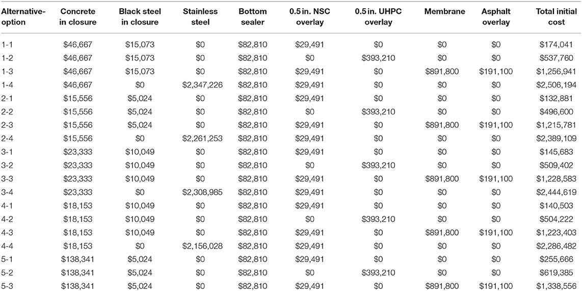
Table A1. Breakdown of material initial cost analysis for alternative-option.
Keywords: service life, life cycle cost analysis, closure joint, accelerated bridge construction, bridges, normal-strength concrete, ultra-high performance concrete
Citation: Jaberi Jahromi A, Valikhani A, Mantawy IM and Azizinamini A (2020) Service Life Design of Deck Closure Joints in ABC Bridges: Guidelines and Practical Implementation. Front. Built Environ. 5:152. doi: 10.3389/fbuil.2019.00152
Received: 25 September 2019; Accepted: 31 December 2019;
Published: 21 February 2020.
Edited by:
Marija Kuster Maric, University of Zagreb, CroatiaReviewed by:
Monique Hite Head, University of Delaware, United StatesDryver R. Huston, University of Vermont, United States
Copyright © 2020 Jaberi Jahromi, Valikhani, Mantawy and Azizinamini. This is an open-access article distributed under the terms of the Creative Commons Attribution License (CC BY). The use, distribution or reproduction in other forums is permitted, provided the original author(s) and the copyright owner(s) are credited and that the original publication in this journal is cited, in accordance with accepted academic practice. No use, distribution or reproduction is permitted which does not comply with these terms.
*Correspondence: Azadeh Jaberi Jahromi, YWphYmUwMDJAZml1LmVkdQ==; Islam M. Mantawy, aW1hbnRhd3lAZml1LmVkdQ==