- 1Structural Xploration Lab, Swiss Federal Institute of Technology Lausanne (EPFL), Fribourg, Switzerland
- 2Applied Mechanics and Computing Laboratory, Swiss Federal Institute of Technology Lausanne (EPFL), Lausanne, Switzerland
- 3Department of Architecture, Faculty of Engineering Science, KU Leuven, Leuven, Belgium
This paper presents optimization methods to design frame structures from a stock of existing elements. These methods are relevant when reusing structural elements over multiple service lives. Reuse has the potential to reduce the environmental impact of building structures because it avoids sourcing new material, it reduces waste and it requires little energy. When reusing elements, cross-section and length availability have a major influence on the structural design. In previous own work, design of truss structures from a stock of elements was formulated as a mixed-integer linear programming (MILP) problem. It was shown that this method produces solutions which are global optima in terms of stock utilization. This work extends previous formulations to stock-constrained optimization of frame structures subject to ultimate and serviceability limit states hence expanding the range of structural typologies that can be designed through reuse. Fundamental to this method is the globally optimal assignment of available stock elements to member positions in the frame structure. Two scenarios are considered: (A) the use of individual stock elements for each member of the frame, and (B) a cutting stock approach, where multiple members of the frame are cut from a single stock element. Numerical case studies are presented to show the applicability of the proposed method to practical designs. To carry out the case studies, a stock of elements was inventoried from shop drawings of deconstructed buildings. Results show that through reusing structural elements a significant reduction of embodied greenhouse gas emissions could be achieved compared to optimized structures made of new elements.
Introduction
Structural optimization is often employed to improve the performance of load bearing systems subject to a given set of boundary conditions. This includes, for instance, maximization of material usage efficiency through minimization of the structure weight. Optimal structure layouts can be obtained through optimization of the structure geometry, the topology and the member cross-section sizing (Rozvany et al., 1995). Often, in sizing optimization of structures the cross-section dimensions are treated as continuous design variables. In practice, because only a limited catalog of standard cross-sections is available, discrete sizing optimization should be employed (Toakley, 1968). This paper considers discrete sizing optimization where the design problem is further constrained by quantities and lengths of available elements.
Trusses and frames are among the most utilized types of structures for practical applications. It is common practice to model truss structures as pin-jointed assemblies whose members are subject to axial forces only. Frame structure models instead comprise rigid connections and members subject to bending moments, shear and axial forces. For trusses, an extensive review of optimization methods involving discrete design variables (cross-sections) is given by Stolpe (2016). Many of these methods are based on metaheuristics, for instance genetic algorithms (Deb and Gulati, 2001; Kaveh and Kalatjari, 2002) or particle swarm optimization (Li et al., 2009) among others. In general, common drawbacks related to black-box metaheuristic algorithms are the potentially large number of structural analysis required (Stolpe, 2016) and the lack of proven global optimality. Discrete sizing and topology optimization of trusses based on mixed-integer linear programming (MILP) has been presented by Ghattas and Grossmann (1991) and Rasmussen and Stolpe (2008) among others. The benefit of MILP is the possibility to obtain solutions which are proven global optima. This problem was efficiently solved by employing the simultaneous analysis and design (SAND) approach (Haftka, 1985), where design variables and state variables (e.g., member forces and nodal displacements) are treated as optimization variables. SAND is different from nested analysis and design (NAND) because it avoids the need to perform explicit structural analysis and design sensitivity analysis at each optimization iteration (Arora and Wang, 2005).
Frame optimization involves a larger number of design variables with respect to truss optimization because the internal force variables include bending moment, shear and axial forces and the degrees of freedom include translations and rotations. Reviews of structural optimization methods for frames are given in Thanedar and Vanderplaats (1995), Arora (2000), Saka and Geem (2013), and Van Mellaert et al. (2018). Similar to truss optimization, a large amount of works on this subject is based on stochastic optimization. Examples include genetic algorithms (Camp et al., 1998; Kripakaran et al., 2011), harmony search (Degertekin, 2008), and ant colony optimization (Kaveh and Jahanshahi, 2008). In addition to heuristic methods proposed in the literature, Kanno (2016) has presented global optimization methods for the compliance minimization of frame structures based on mixed-integer second-order cone programming. Van Mellaert et al. (2018) have presented global discrete sizing optimization of frames based on MILP. Different to previous work, the formulation given in Van Mellaert et al. (2018) allows to take into account loads distributed on the members, which are common for structural design.
Minimizing material input through weight optimization is one option to reduce energy and greenhouse gas (GHG) impacts from material production (e.g., steelmaking) (Pongiglione and Calderini, 2016). This way structural optimization can reduce embodied energy and GHG emissions and contributes to reducing the environmental impact of building structures (Lagaros, 2018). Recently, another strategy to reduce the environmental impact of civil structures has received attention in practice and research: the reuse of structural components (Addis, 2006; Gorgolewski, 2017; Brütting et al., 2019d). Reusing structural elements avoids sourcing new material, it reduces waste and it requires little energy (Iacovidou and Purnell, 2016; Vares et al., 2019). As pointed out by Gorgolewski (2008), reuse is unlike conventional structural design because reclaimed structural elements available in a stock become a design input.
Combinatorial optimization subject to a limited amount of resources is common in operations research. A well-known example is the assignment problem for the optimal allocation of tasks to available resources (e.g., workers) (Votaw and Orden, 1952; Bierlaire, 2015). Another example is that of bin-packing problems for the optimal packing of products into available containers with the objective to minimize the number of used containers (Johnson, 1974; Delorme et al., 2016). The bin-packing problem closely relates to the one-dimensional cutting stock problem (Gilmore and Gomory, 1961; Delorme et al., 2016) where the objective is the minimization of trim losses for materials that are in the form of one-dimensional stocks such as steel rebars or structural steel sections (Salem et al., 2007).
These combinatorial problems also arise when reticular structures (trusses and frames) are designed to fit given stock element characteristics, e.g., cross-section dimensions and lengths. Two scenarios are considered in this work: (A) the 1-to-1 assignment of stock elements to member positions in a structure, and (B) the cutting stock problem to optimally partition stock elements into structure members. Both scenarios are typical design tasks to address in order to reuse structural elements in new constructions.
Stock-constrained structural optimization has received little attention so far. In Fujitani and Fujii (2000) assignment optimization of plane frames from a stock of one-time available cross-sections has been carried out through evolutionary algorithms with the objective to minimize the weight of the structure but without accounting for available element lengths. Strategies based on heuristics developed to solve bin-packing problems have been employed to fit a stock of wood logs to statically determinate trusses by Bukauskas et al. (2017). Different to previous works, Brütting et al. (2018) formulated the assignment and topology optimization of trusses taking into account ultimate and serviceability limit states as well as stock element cross-section and length availability with the objective to reduce the structure embodied energy. This method is based on discrete structural optimization formulations given by Ghattas and Grossmann (1991) as well as Rasmussen and Stolpe (2008) and thus produces globally optimal solutions. The method has been successfully applied to the design of relatively complex structures including a train station roof case study (Brütting et al., 2019a) and 3D trusses (Brütting et al., 2019b). A cutting stock formulation has been presented in Brütting et al. (2019c). Application of this method to the design of trusses has shown that the possibility to partition a stock element into multiple members produces solutions with less cut-off waste compared to solutions obtained through assignment only.
This paper combines previous works (Brütting et al., 2018; Van Mellaert et al., 2018) to extend the application domain of stock-constrained structural optimization and component reuse to frame structures. The formulations for the assignment and cutting stock optimization are given in sections Assignment Optimization and Cutting Stock Optimization, respectively. Different to previous work (Brütting et al., 2018, 2019c), in this study the minimization of GHG emissions is the optimization objective. Section Embodied Greenhouse Gas Emissions Quantification gives the computation of GHG emissions through Life Cycle Assessment. In section Case Studies, two steel structure case studies are presented: (1) a three-bay-three-story frame taken from Van Mellaert et al. (2018), and (2) the design of a 600 m2 two-story office building. The first case study is carried out to benchmark embodied GHG emissions of structures made from reused elements against those of weight optimized solutions made of new steel taken by Van Mellaert et al. (2018). The second case study is the conceptual design of a two-story office building which is made of reused structural elements. Different from previous work (Brütting et al., 2019b,c) in which the stocks were randomly defined, in this work stock elements have been inventoried through shop drawings of obsolete steel buildings (section Boundary Conditions and Element Stock). In section Discussion the solutions and computational performance of the optimization method are discussed. Section Conclusion concludes the findings of this study.
Method
In the following, the term member denotes a beam at a certain position in a structure. The term element denotes the component available for reuse from a stock S. Stock elements are characterized by material properties (density, elasticity, yield strength), cross-section dimensions (area, area moment of inertia), length, and origin (to estimate transport distances).
The design process is explained through an example which is illustrated in Figure 1. Figure 1A shows a frame with m = 3 members. Figures 1B,C show bar charts that represent the stock through gray bars that indicate the element lengths. The cross-section of each element in the stock is drawn at the bottom of each bar. In this example, four element groups g of unique length and cross-section are available. In total the stock contains eight individual elements j. Two strategies to reuse stock elements are studied in this work: (A) the 1-to-1 assignment of stock elements to positions in the structure, and (B) a cutting stock approach in which stock elements can be partitioned into multiple members. The optimal element reuse for both strategies is obtained as the solution of the optimization problems formulated in sections Assignment Optimization and Cutting Stock Optimization. Figures 1B,C show an example solution for strategies (A) and (B), respectively. The black bars overlaid on the gray ones indicate the length of the frame members and the optimal use of stock elements. The excess length between black and gray bars indicates cut-off.
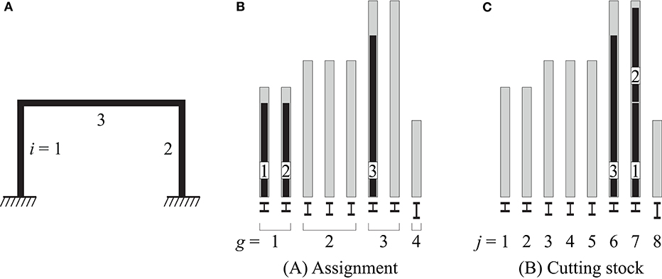
Figure 1. Optimization method: (A) structure layout, (B) element stock and optimal assignment, (C) element stock and optimal cutting pattern.
Assignment Optimization
The assignment of stock elements to the frame layout is formulated as a combinatorial problem, which is denoted by (A).
In (A), binary design variables tig ϵ {0;1} define whether an element of stock group g is used at member position i (tig = 1) or not (tig = 0). The vector t collates all binary design variables tig. The objective function (Equation 1) is the sum of all ‘costs’ c associated to assignment tig. Numeric values for c with respect to embodied GHG minimization are given in section Embodied Greenhouse Gas Emissions Quantification. Equation (2) ensures that exactly one stock element is assigned to each member. Through Equation (3), the assignment of stock elements is constrained to the number of available elements per group ng. Equation (4) constrains the assignment to stock elements with a length lg greater than or equal to the corresponding frame member length .
Section Structural Analysis explains how formulation (A) is completed with structural constraints. Note that the main difference between (A) and typical discrete structural optimization methods with catalogs of commercial cross-sections (Ghattas and Grossmann, 1991; Rasmussen and Stolpe, 2008) are the constraints on the number of available elements and their length (Equations 3 and 4).
Cutting Stock Optimization
Formulation (B) extends (A) to a cutting stock problem in order to allow the partitioning of each stock element into one or more structure members. This requires to treat every stock element j individually instead of in groups g, as done in (A). For this reason, a binary design variable tij is employed to define whether a part of stock element j is used at position i or not. In addition, binary variables yj ϵ {0, 1} are included to identify whether element j is at least partly used in the optimal design (yj = 1) or remains fully unused (yj = 0). The vector y collates all binary design variables yj. Both these extensions increase the number of binary design variables with respect to (A).
The objective function (Equation 5) is the sum of all costs c related to using element j and all costs c for installing parts of j at position i in the structure. Numeric values specific to embodied GHG emissions are given in section Embodied Greenhouse Gas Emissions Quantification. Equivalent to Equation (2) in (A), the assignment for each frame member is ensured by Equation (6). Equation (7) constrains the sum of the member lengths to be shorter or equal than the element length lj from which the members are cut out.
Structural Analysis
Formulations (A) and (B) are completed by structural constraints such as equilibrium between member end forces and external loads, compatibility of nodal displacements and member deformations, as well as by displacement and stress limits. The formulation of these conditions as linear equality and inequality constraints is given in Van Mellaert et al. (2018). Key aspects of this formulation are summarized here, for a detailed description the reader is referred to Van Mellaert et al. (2018). Following the simultaneous analysis and design approach (Haftka, 1985), structural analysis is part of the optimization formulation by treating member end forces as well as nodal displacements and rotations as continuous state variables. Stress constraints are formulated as:
The internal forces (N, My, Vz) are computed through the Bernoulli beam theory at defined locations along frame members. In Equation (8) stresses normal to the section are obtained as the sum of the axial force N divided by the cross-section area A and the bending moment My divided by the elastic section modulus Wel,y. The normal stress so obtained is limited to be lower than the material yield strength fyd both in tension and compression. Shear stresses are computed dividing the shear force Vz by the shear area AV, z and bounded as indicated in Equation (9). Deformations along members are similarly computed via Bernoulli beam theory from member end displacements and rotations. Deformations are constrained to common serviceability limits used in practice, for example mid-span deflection bounds of u(x = 0.5) ≤ /300.
For the case study presented in section Office Building, the method given in Van Mellaert et al. (2018) is extended to account for the interaction between member buckling and bending moments. This extension was initially proposed by Van Mellaert (2017) and Tiainen et al. (2018) for Eurocode-conform optimization of frames. The Swiss steel design code, SIA263 (2013) constrains the cross-section utilization for beam members subject to compression force N and bending moment My to:
In Equation (10), Nk,⊥y,Rd is the buckling resistance perpendicular to cross-section y-axis (SIA263, 2013), Nc,⊥y is the Euler-buckling load and Mel,y,Rd the elastic cross-section moment resistance. According to SIA263 (2013) for frame columns, a buckling length of 1.0 l and a material safety factor of ym = 1.1 is considered for the computation of Nk,⊥y,Rd and Nc,⊥y. Equation (10) is a non-linear function of N and My. To incorporate the buckling constraint into the MILP formulation proposed in this work, Equation (10) has been linearized through a first order Taylor expansion at the point N = Nk,⊥y,Rd/2:
Figure 2 shows an example of the feasible domain for normal force and bending moment interaction for an HEA 160 section assigned to a column with 3.50 m length. In Figure 2, NRd = A ·fyd denotes the normal force capacity of the cross-section. The feasible domain for the cross-section utilization is indicated by a white surface. The governing constraint in tension is the linear inequality expressed through Equation (8). In compression, the feasible domain is bounded by (1) the buckling resistance Nk,⊥z,Rd in the weak cross-section direction (light gray area), and by (2) the linear expansion (Equation 11) which is indicated by blue lines. Employing the linear expression is conservative because it “cuts away” more from the feasible domain than the actual non-linear constraint (Equation 10, red dashed line).
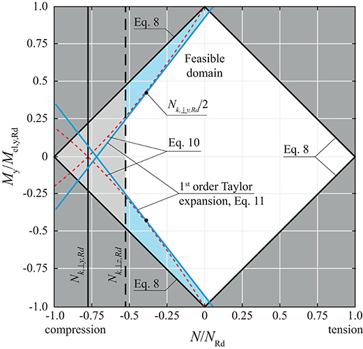
Figure 2. Example of the feasible domain for normal force and bending moment interaction for an HEA 160 section assigned at a column of 3.50 m length.
Embodied Greenhouse Gas Emissions Quantification
Life Cycle Assessment is employed to quantify embodied GHG emission coefficients for reused structural elements and for new steel elements produced with recycled content. These coefficients are then used in the optimization objective functions (Equations 1 and 5) to minimize the total structure embodied GHG. This LCA approach has been previously taken in Brütting et al. (2018) to minimize the structure embodied energy through reuse. It is adapted here for GHG emissions in unit of kgCO2eq and updated to the Swiss context of the case studies presented in section Case Studies.
Figure 3 summarizes the two scenarios, “Reuse” and “Recycling” considered in the assessment. For both scenarios, the starting point is an obsolete building structure. In the Reuse case, the structure is deconstructed into stock elements by workers and a diesel-powered mobile crane. From the stock obtained after deconstruction, the elements selected through optimization (A) and (B) are transported to a fabrication facility to be cut to the required length. Cut-off scrap is transported to a local recycling facility. Finally, the frame parts are transported on site to be assembled using a diesel-powered mobile crane.
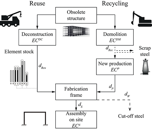
Figure 3. LCA assumptions and system boundary, embodied GHG emission coefficients (EC), transport distances (d).
For the Recycling case, the obsolete building is demolished by excavators and steel scrap is brought to a local recycling facility. New steel elements are produced with ~90% recycled content (Wyss and Frischknecht, 2014; KBOB, 2016). It has been conservatively assumed that new steel elements are produced with exact lengths and do not generate cut-off waste. Fabrication of the frame parts from new steel elements and assembly on site is similar to the Reuse case.
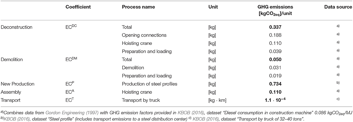
For all processes in Figure 3 except “Fabrication,” the associated embodied GHG coefficients are obtained from published sources and governmental databases (Table 1). For example, fuel consumption requirements of equipment utilized to demolish or deconstruct steel buildings has been assessed by Gordon Engineering (1997). Emission factors for new steel production and transportation are taken from the Swiss federal LCA database, KBOB (2016). Emissions for fabricating frame parts and connections is assumed identical for both “Reuse” and “Recycling” and thus neglected in the computation. For “Assembly” related emissions, the hoisting of the frame is included because it can vary depending on the structure weight. The inclusion of other assembly-related processes and of the building use is beyond the scope of this paper and has been assumed identical in both scenarios.
For the Reuse case, the process emission factors are combined to obtain the “cost” indices defined in the objective functions of problems (A) and (B) (Equations 1 and 5). For assignment problem (A) they are computed as:
where ag is the cross-section area and ρg the material density of an element from stock group g. Equation (12) sums all emissions for deconstruction and transport with respect to the mass of the stock elements, the emissions for transport and assembly with respect to the mass of the structure members, and emissions for transport of cut-off scrap. Transport distances are denoted by d (see Figure 3 for notation). Summing the cost indices over the structure members i and element groups g gives the total embodied GHG emission for a solution obtained through formulation (A) (see also Equation 1):
For the cutting stock problem (B), the cost factors c and c are computed as:
Equation (14) collects all emissions with respect to the stock element mass. Equation (15) sums transport and assembly impacts for the frame members. Emissions from transporting cut-off scrap (Figure 3) are computed through accounting for transport of the complete stock element over distance dW and then deducing emissions for those parts of the element that are used in the frame (negative sign in Equation 15). Summing the cost indices over the stock elements j and the structure members i gives the total embodied GHG emission for a solution obtained through formulation (B) (see also Equation 5):
Embodied GHG minimization in (A) and (B) groups multiple objectives such as the minimization of the number of reused elements (bin-packing problem), minimization of the structure weight as well as of cut-off waste (cutting stock problem).
For new-steel structures, GHG emission coefficients are related solely to the structure mass M. This means that, given the LCA assumptions taken in this work, weight minimization or the minimization of embodied GHG emissions will produce equivalent optimal designs. Embodied GHG emissions for new-steel structures include demolition, new steel production, assembly and transport:
Global Optimization
The MILP problems given in sections Assignment Optimization and Cutting Stock Optimization can be solved to global optimality through well-established algorithms such as branch-and-bound methods (Nemhauser and Wolsey, 1988; Bierlaire, 2015). The availability of proven global optima allows for a rigorous benchmarking between reuse vs. new construction solutions. In a branch-and-bound method, a lower bound fLB of the objective function value is computed at each iteration by solving continuous linear programming relaxations. The best integer feasible solution (all binary variables are either 0 or 1) obtained during iterations is denoted as the upper bound fUB. At every iteration the optimality gap (or “MIP-gap”) is computed as:
The MIP-gap gives a measure of the quality of the best integer feasible solution fUB obtained so far. In other words, if at any branch-and-bound iteration the solver is manually terminated, the worst-case difference to expect between the global optimum and the solution at termination is known. When the gap is zero, global optimality of the solution is verified. Information on global optimality in MILP is an advantage compared to metaheuristic methods such as population-based algorithms. In this work, for numerical stability a small MIP-gap value of 0.01% is employed as a termination criterion. All computations are carried out on an Intel i7-6820HQ CPU employing the commercial software Gurobi 8.1 (Gurobi Optimization, 2019).
Case Studies
Boundary Conditions and Element Stock
For the case studies presented in the following sections Three-Bay-Three-Story Frame and Office Building, the building site is assumed to be located in Fribourg, Switzerland (Figure 4A). Scenarios of Reuse and Recycling (section Embodied Greenhouse Gas Emissions Quantification) are compared in both case studies.
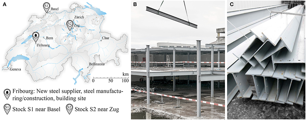
Figure 4. (A) locations of the stock elements, building site, new steel supplier and steel manufacturer; (B) disassembly of a steel structure at location S1; (C) stockpile of reclaimed steel elements. Map (A) by Tschubby (2005) CC-BY-SA 3.0; pictures (B) and (C) courtesy of baubüro in situ, Basel, Switzerland.
For structures made of reused elements the study is based on a realistic element stock that originates from obsolete steel buildings located in Switzerland. Figure 4A shows a map that indicates the location of two element stocks S1 and S2 near the cities of Basel and Zug. Figures 4B,C give an example of the deconstruction of a steel building and stockpiled elements. Approximately 55 tons of these steel beams will actually be reused for the construction of an office building in Basel which is planned by the Swiss architecture firm baubüro in situ (Stahlbau Zentrum Schweiz, 2019) who have provided these data. For the assessment of embodied GHG emissions, transport distances dReu for stock elements from S1 and S2 to the steel manufacturer in Fribourg are set to 130 and 150 km respectively.
For “Recycling” cases, it is assumed that steel elements from the demolished buildings at locations S1 and S2 are recycled in a facility located at a distance of 10 km from each site. Then new steel elements are produced and sourced from a supplier that is assumed to be in proximity of the building site. New elements are transported from the supplier to the manufacturer over a distance dP = 10 km.
Frames are fabricated either from reused elements or with new steel sections and then transported over a distance dS = 10 km to the building site. Cut-off from reused elements is transported for 10 km to a local recycling facility (dW).
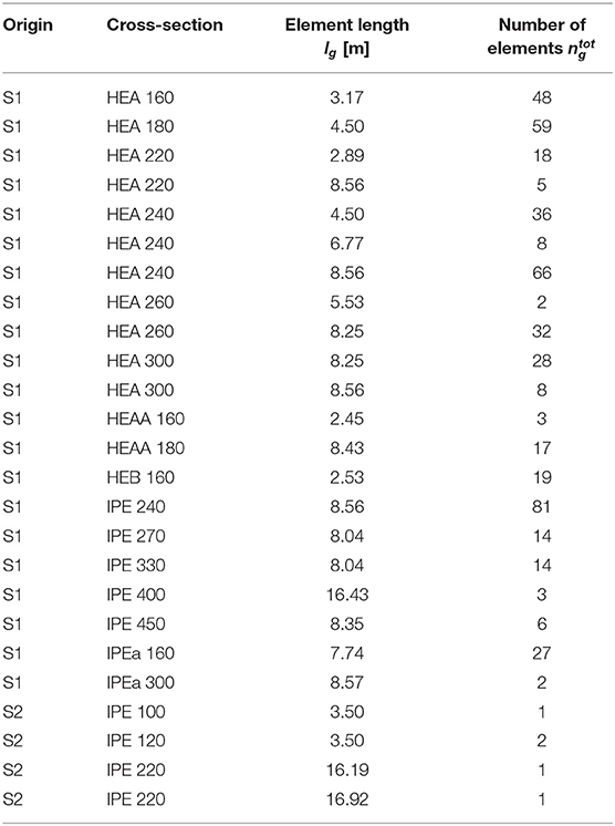
Material properties, cross-section shapes and lengths of stock elements have been extracted from shop drawings of the abovementioned obsolete buildings. Table 2 gives the inventory of 25 groups totaling 501 elements. The stock consists primarily of standard HEA and IPE sections. For all elements the drawings report a grade S235 steel with a yield strength of 235 MPa, a Young's modulus of 210 GPa and a density of 7,850 kg/m3. For comparison, new elements made of recycled steel are also assumed to be made of S235 steel.
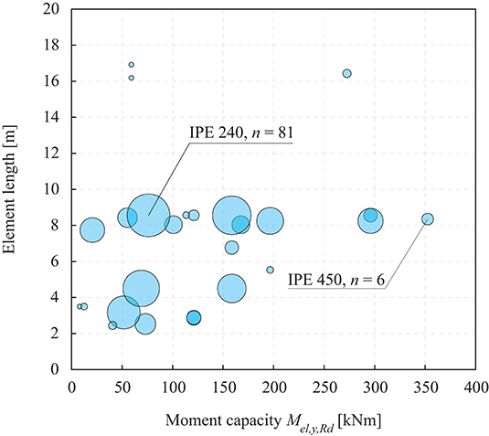
Figure 5 shows a scatter diagram indicating the distribution of element lengths and elastic bending moment capacities for all inventoried elements.
Three-Bay-Three-Story Frame
System
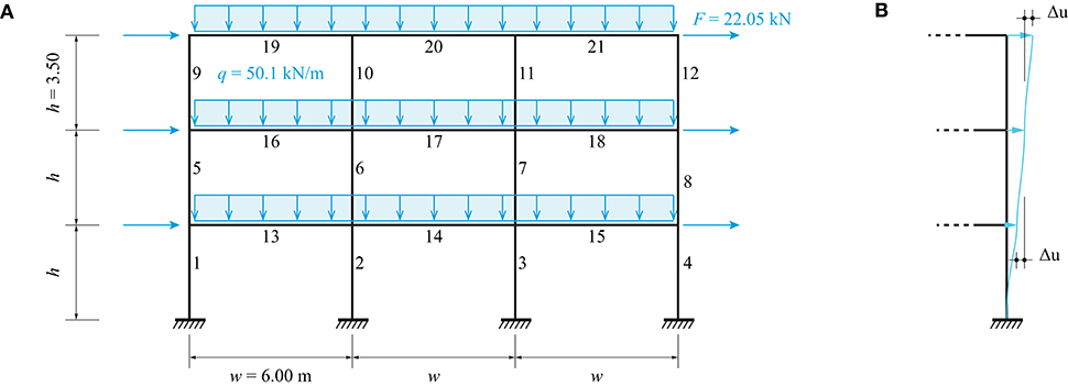
Figure 6A shows a three-bay-three-story frame made of 21 beams. This system is adopted here to benchmark the solutions of optimization problems (A) and (B) (section Method) using the inventoried element stock described in section Boundary Conditions and Element Stock against the minimum-weight solution obtained in Van Mellaert et al. (2018).
A single load case combines a distributed load of 50.1 kN/m applied on each floor and a horizontal wind load of 22.05 kN applied as indicated in Figure 6A. To account for wind loads from both directions, column members are constrained to have pair-wise symmetrical cross-section assignment (for example members 1 and 4, 2 and 3, etc.). In addition, all horizontal floor beams are required to have identical cross-sections. This is achieved by adding linear equality constraints to problems (A) and (B). For instance, for problem (A) the assignment of identical cross-sections for column members 1 and 4 is obtained through:
In Equation (19) the constants CSg are integer numbers which uniquely identify different cross-section shapes available in the stock. Elements from different stock groups but of identical section shape have the same CS-number. Equation (19) can be equivalently extended to (B) and to new steel section catalogs.
Stresses are evaluated at three locations x along each member i (x = 0, x = /2, and x = ). Mid-span deflections are limited to w/200 for all horizontal beams. For each column the inter-story drift Δu is limited to h/300 = 11.7 mm as shown in Figure 6B. To allow a comprehensive comparison with the study in Van Mellaert et al. (2018), member buckling and bending moment interaction (section Structural Analysis) is not considered in this case study.
Six different cases are studied. Cases (1)–(3) consider the optimization of the frame structure with new steel elements only. Cases (4)–(6) consider the optimization of the frame subject to the element stock described in section Boundary Conditions and Element Stock. In each case, the objective is to minimize embodied GHG emissions. In case (1) all standard sections from HEA 100 to HEA 1000 are available (equivalent to the study by Van Mellaert et al., 2018). In case (2) the catalog contains all standard sections from IPE 80 to IPE 600. In case (3) the catalog contains all standard HEA as well as IPE sections. IPE sections are included in this study to allow for a comparison with the reuse cases because the stock contains both HEA and IPE sections.
In case (4) the frame is designed through assignment optimization (A). Case (5) “rationalizes” the solution obtained in case (4) through applying cutting stock optimization (B) to the layout obtained from (A) but without structural constraints (section Structural Analysis). In other words, the optimal assignment of cross-sections from (A) is kept and an improved cutting pattern whereby multiple members are cut from one stock element is sought. Finally, in case (6) the frame is designed as the solution of problem (B) subject to structural constraints. For cases (4)–(6), the availability of stock elements n (Table 2) is reduced by:
This reduction simulates the construction of three identical frames arrayed in the out of plane direction to form a building. After applying Equation (20) and considering that the shortest structure member has a length of 3.50 m (Figure 6), the stock is reduced to 129 elements per frame.
Results
Figures 7A–C show the optimal cross-section sizing for cases (1)–(3) made of new steel. The line thickness in Figure 7 is proportional to the cross-section height. Figures 7D–F show at the top the optimal structures for cases (4)–(6) and at the bottom the corresponding stock element assignment charts. Only the subset of reused elements is shown in the stock diagrams and not the complete element stock made of 129 elements. As expected, the solution produced through (A) in case (4) results in only one stock element assigned per member position. However, it is clear that the two IPE 330 and two IPE 450 members could be cut from one stock element each instead (Figure 7D). This is shown in case (5) where the solution of (4) has been improved through cutting stock optimization (B) while keeping the same cross-sections as obtained in case (4). In addition, HEA 240 elements are grouped and cut from longer elements in case (5). Further improvements are achieved in case (6) where IPE 330 elements replace HEA 240 elements because the former have a higher moment-resistance-to-mass ratio than the latter.
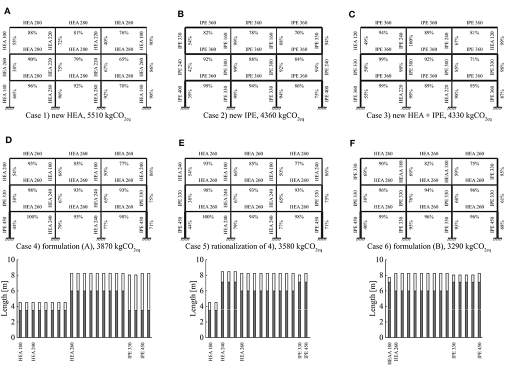
Figure 7. Optimization results: (A–C) new steel minimum-weight benchmark cases (1)–(3); (D–F) optimum designs made of reused elements for cases (4)–(6) employing assignment and cutting stock optimization. Percentage values show the maximum cross-section utilization of each member.
Table 3 summarizes the results for all six cases. The optimal solution for case (1) has a mass of 6,130 kg and embodied GHG emissions of 5,510 kgCO2eq. In cases (1) and (2) larger cross sections are assigned to some of the exterior columns located at the first and second floor with respect to the exterior columns located at the floor below. Because of the horizontal wind load and the strict inter-story drift limits, cross section sizing does not necessarily follow the vertical load-path. In some cases, it is required to form an internal rigid frame to resist lateral loading more effectively (Van Mellaert et al., 2018). Combining new HEA and IPE sections in case (3) produces the configuration with a minimum mass of 4,830 kg and embodied GHG of 4,330 kgCO2eq. The optimal design in case (3) is primarily made of IPE sections as a result of the better moment-resistance-to-mass ratio of IPE sections compared to HEA sections. In case (4) stock elements with a total mass of Ms = 9,090 kg are reused but the structure mass is 6,080 kg because 3,010 kg steel is cut off (ΔM) to fit the elements. For the solution of case (5), although all cross-sections shapes are not changed from case (4) and hence the structure mass remains identical, stock mass and cut-off waste are reduced because multiple members are cut from single stock elements through cutting stock optimization (B). The solution for case (6) instead, which is obtained through formulation (B) subject to structural constraints, has the lowest embodied GHG emissions (3,290 kgCO2eq) as well as the lowest mass of reused elements MS and cut-off ΔM. Although the solutions obtained through reuse have a higher mass and a lower mean element capacity utilization with respect to the solutions made of new steel, reusing structural elements results in a significant reduction of embodied GHG emissions.
In a “hypothetical” scenario where all members of case (3) would be part of the stock, the solution of (3) could be built with identical mass (4,830 kg) but from reused elements only. This hypothetical solution would embody 2,230 kgCO2eq, which is the overall minimum possible and about 2/3 of the 3,290 kgCO2eq of case (6).
Assignment optimization (A) for cases (1)–(4) results in MILPs with a number of binary variables between 315 and 882. Instead, cutting stock formulation (B) for cases (5) and (6) requires treating each stock element individually and therefore it increases the number of binary variables to 2838. The total computation time to solve cases (1)–(3) to global optimality (MIP-gap = 0.01%) is 2,000, 480, and 8,000 s, respectively. However, the optimum (best upper bound fUB) is obtained earlier in the branch-and-bound process (Table 3, column “Computation time to reach optimum”). The remaining time is required to reduce the MIP-gap through increasing lower bounds (fLB) over succeeding iterations until global optimality is verified within the prescribed tolerance (section Global Optimization). In the branch-and-bound optimization while a search tree is explored, integer feasible solutions (upper bounds) are stored and retrievable. For instance, in case (4) a solution with 4.9% higher objective value than the global optimum was obtained in 360 s (Table 3, footnote ii) while the global optimum was reached in 1,500 s and global optimality was proven 700 s later (total time 2200s). In practice, the optimization process could be terminated as soon as a solution is deemed satisfactory.
Improving case (4) through cutting stock optimization (B) can be carried out at little computational cost (case 5 solution has been obtained in 0.1 s) because the optimal cross-section assignment is already given from case (4) and only an improved cutting pattern must be found. Instead, cutting stock optimization (B) subject to structural constraints (case 6) is computationally more demanding. Global optimality could not be proven after 360·103 s (4.2 days). Optimization was interrupted when the MIP-gap was 21%. In other words, it is unknown if an integer feasible solution with objective value between 3,290 and 2,600 kgCO2eq (= 3,290·0.79) exists. However, the best solution for case (6) has been obtained after 4,400 s reducing GHG emissions by 290 kgCO2eq with respect to case (5).
Office Building
System
This case study can be thought of as a conceptual design of a two-story office building subject to the stock of elements described in section Boundary Conditions and Element Stock. Figure 8A shows a perspective view of the structure which consists of four main frames lying in the Y-Z-plane and arrayed along the X-direction. Secondary beams of span lX = 8.0 m are positioned between the main frames. This span is chosen considering that most of the stock elements are longer than 8.0 m (Figure 5). Secondary beams are placed with a = 1.2 m distance, which is obtained through preliminary calculations and considering moment resistance availability (Figure 5). Three types of loads are considered: a distributed floor load q, a snow load s and a wind load w applied on the main frames and secondary beams as indicated in Figures 8B–E. The end frames indicated by ① take load contributions from one half of the adjacent secondary beams (Figure 8B). The interior frames indicated by ② take load contributions from both sides (Figure 8C). Wind loads are distributed from a façade system to the edge beams (Figure 8D) and further to the frames (nodal loads W). Stability of the whole structure in X-direction is assumed to be provided by a concrete core, cross-bracing or shear walls.
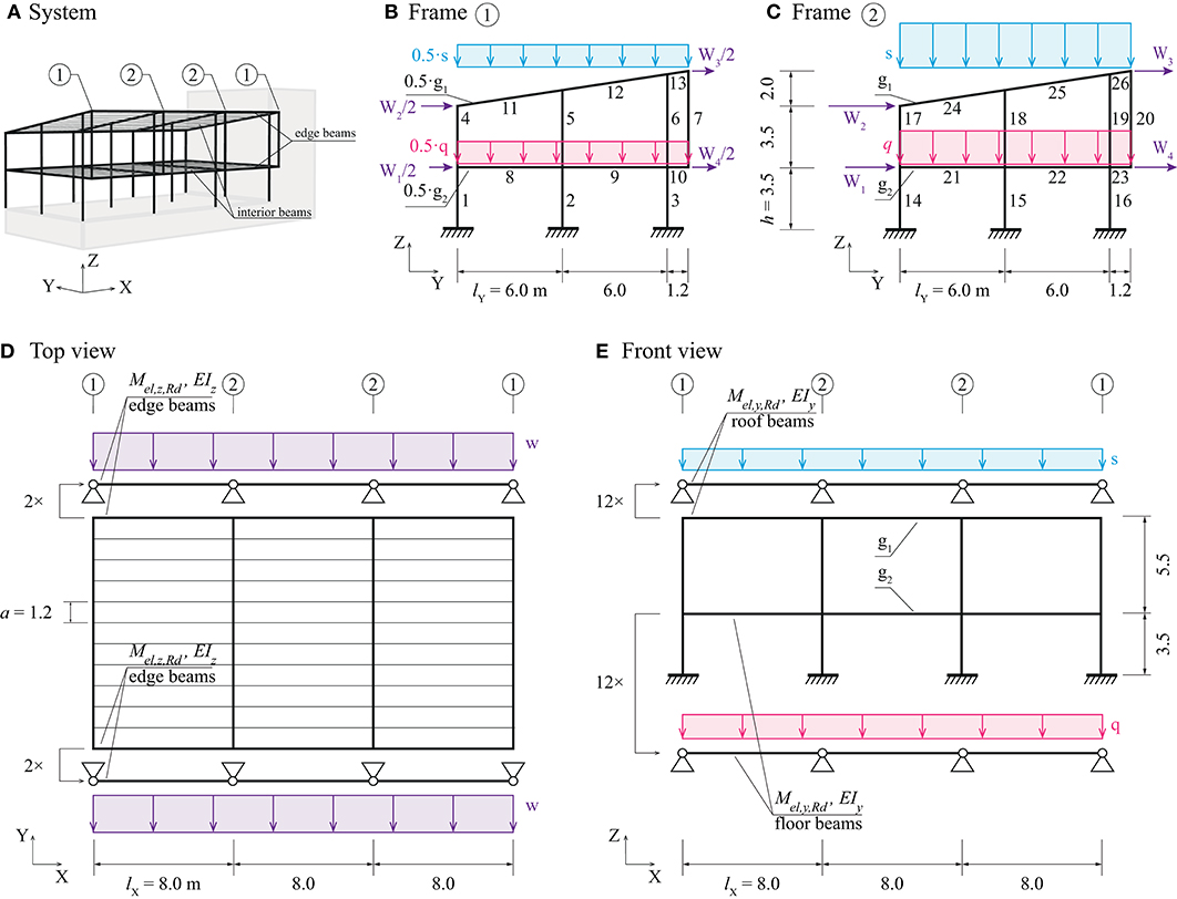
Figure 8. Office building structure: (A) layout, (B) end frame in Y-Z plane, (C) internal frame in Y-Z plane, (D) top view, (E) front view.
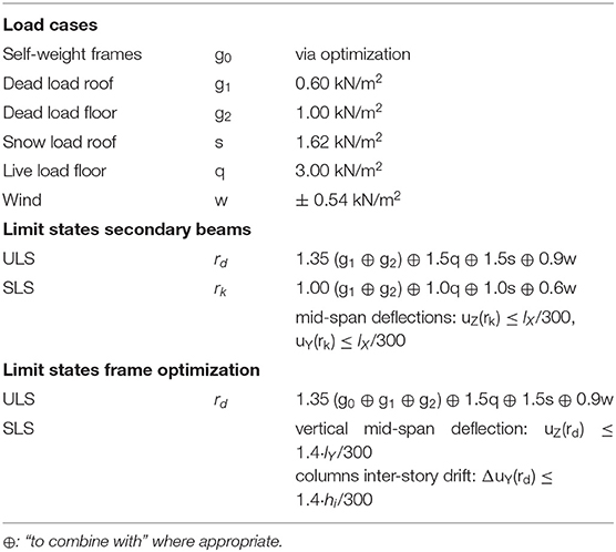
Table 4 shows the assumed load cases and limit states, all based on the Swiss standards SIA260 (2013) and SIA261 (2014). It is assumed that the combination of dead load, snow load and reduced wind load is the governing load combination. For simplicity, it is assumed that the self-weight of secondary beams is included in the dead loads g1 and g2.
The Swiss standard, SIA260 (2013) distinguishes ultimate (ULS) and serviceability (SLS) limit states. Typically, for serviceability limits only characteristic (non-factored) loads have to be considered (SIA260, 2013).
Design Process
The design process is divided into two-steps: (1) the secondary beams are optimized using the entire element stock, then (2) the main frames are optimized using the remaining stock elements which have not been used for the secondary beams in step (1).
Secondary structure
The set L of 72 single-span secondary beams is optimized through the cutting stock formulation (B). In this case, stress and deflection constraints are implemented through well-established formulations for single span beams instead of the formulation given in Van Mellaert et al. (2018). This way any continuous state variables (member forces or displacements) are avoided in the problem formulation. Equation (21) limits bending stresses to a maximum utilization ratio of 1. The interaction of bending moments caused by wind and snow or floor loads on the edge beams (see Figures 8D,E) is considered with respect to cross-section y- and z-axes. For the interior beams, only moments My caused by snow or floor load are present (rd,y,i = 0). Loads on secondary beams are calculated via their tributary load areas, e.g., rd,z,i = a ·rd for interior beams. Deflections caused by the characteristic loads rk are constrained to serviceability limits (Equation 22).
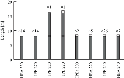
The set of secondary beams is optimized for two cases: (L1) with new steel HEA and IPE sections, and (L2) through cutting stock formulation (B) from the complete stock and subject to the structural constraints expressed in Equations (21) and (22). Figure 9 shows the optimal cutting pattern for case (L2), which has marginal cut-off. Metrics for the structure mass, cut-off, and embodied GHG emissions for secondary beams are given in Table 5 and discussed in section Results.
Main frames
For the optimization of the main frames, element availability n (Table 2) is reduced by removing the 70 elements that have been used for the secondary beams (Figure 9). The reduced availability per element group is denoted by ng'. For the main frames eight different cases are studied. In case (1) the frames are optimized using new elements. Cases (2) to (5) are carried out by applying formulation (A) while cases (6) to (8) apply formulation (B). The end ① and interior ② frames are optimized either separately or simultaneously for all cases. Element availability is reduced to ng = ⌊ng, /4⌋ when the frames are optimized separately (cases 1, 2, and 6) and to ng = ⌊ng'/2⌋ when they are optimized simultaneously (cases 3–5, 7, and 8). In addition, in order to reduce computation time, for cases (6) and (8) the problem size is reduced further such that at most six stock elements per group are available.
To reduce computational complexity only one ULS load case rd is employed in the optimization of the main frames and therefore all SLS deflection limits are increased by a factor 1.4 as a conservative assumption (see Table 4). The formulation given by Van Mellaert et al. (2018) is extended in this study to take into account the self-weight of assigned elements, which is converted to nodal loading as done in Brütting et al. (2018). Stresses are evaluated via Equations (8) and (9) at three locations x along each non-vertical member (x = 0, x = /2, and x = ). In addition, buckling and bending moment interaction is considered for all columns (Equation 11, section Structural Analysis). To account for wind loads from both directions, for simplicity the column members are constrained to have pair-wise symmetrical cross-section assignment (members 1/3, 4/6, 14/16, and 17/19).
Results
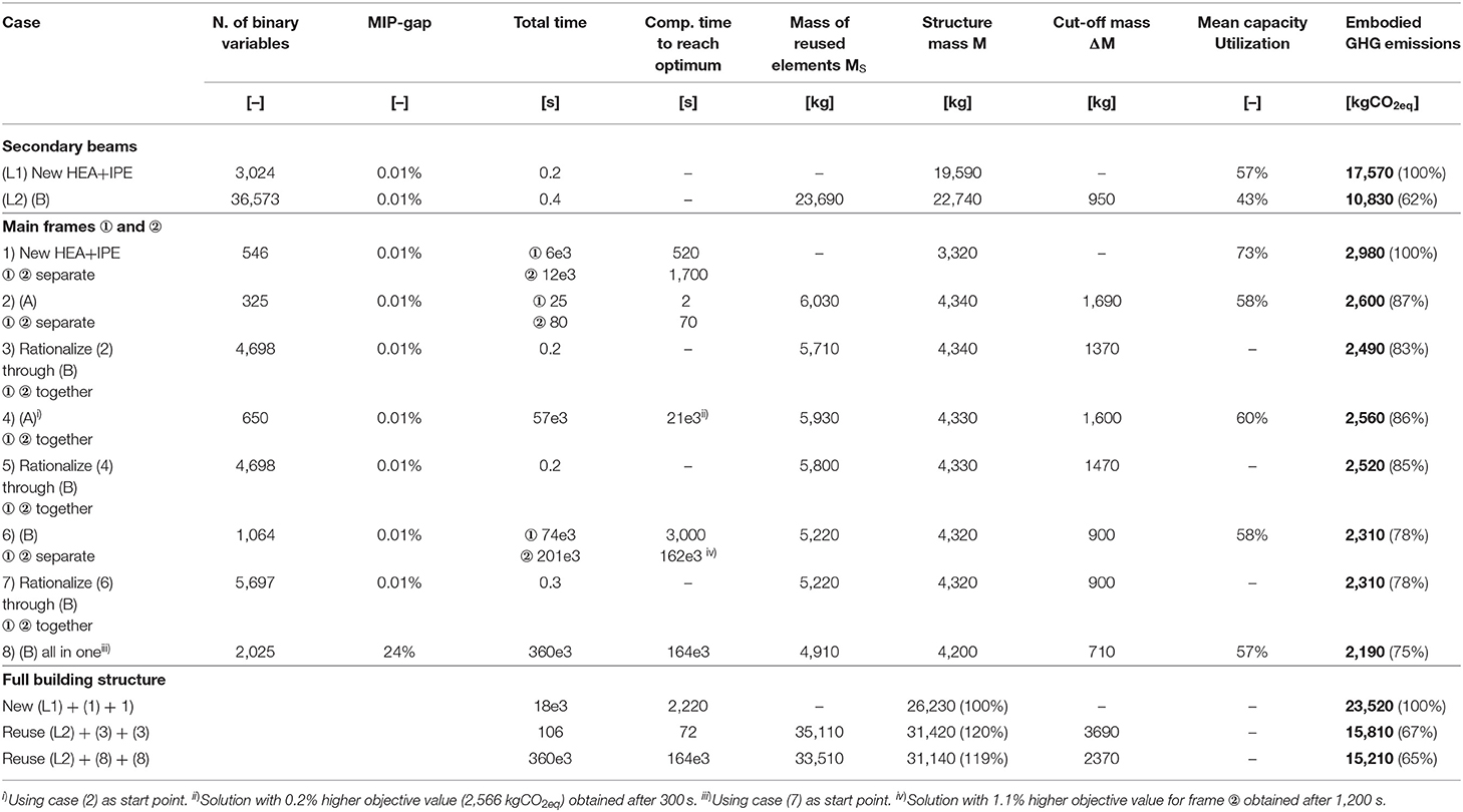
Table 5 shows optimization metrics for secondary beams and main frames. The minimum weight for secondary beams made of new steel (case L1) is 19.6 tons. Reusing steel beams from the stock for secondary beams results in a 16% increase of mass but a 38% reduction of embodied GHG emissions (case L2, 10,830 kgCO2eq).
The optimum main frame design with new HEA and IPE sections (case 1) has a mass of 3,320 kg and embodies 2,980 kgCO2eq. Assignment optimization for frames ① and ② processed separately (case 2) results in designs with a total mass of 4,340 kg and embodied GHG of 2,600 kgCO2eq. Improving case (2) through subsequent cutting stock optimization (case 3) reduces cut-off by 320 kg. Even though the structure of case (3) is 31% heavier than that obtained with new elements (case 1), embodied GHG emissions are reduced by 17% to 2,490 kgCO2eq. Assignment optimization (A) in case (4) for frames ① and ② processed together yields an improved solution (2,560 kgCO2eq) with respect to case (2) (2,600 kgCO2eq). However, in case (5) a subsequent optimization through (B) starting from the solution obtained for case (4), produces a solution with an objective value of 2,520 kgCO2eq, which is marginally higher than that of case (3) (2,490 kgCO2eq). In this case study, improving the cutting pattern through cutting stock optimization (B) was more efficient starting from a solution obtained through separate optimization of frames ① and ②.
Cutting stock optimization (B) subject to structural constraints for frames ① and ② processed separately (case 6), produces a solution with 2,310 kgCO2eq which is better than that obtained through formulation (A) in case 2 (2,600 kgCO2eq). A subsequent optimization through (B) starting from the solution obtained for case (6) and subject to the complete element stock did not produce an improved cutting pattern (case 7). The overall best solution in terms of embodied GHG (2,190 kgCO2eq), stock element mass and cut-off is obtained for case (8) which employs formulation (B) subject to structural constraints and simultaneous optimization of frames ① and ②.
In all cases the mean cross-section utilization is relatively low (43 to 73%). However, maximum mid-span deflections for secondary beams as well as inter-story drifts reach between 93 and 99% of the required limits. This shows that in this case serviceability limits are dominant for the design of the structure.
Figure 10 shows the optimal main frame designs and the optimal cutting of stock elements for case (8). As expected, interior frame ② is made of larger cross-sections than end frame ①. An IPE 400 is assigned to the central ground floor column in frame ② to resist the wind load. Since the stock element with IPE 400 section has a length of 16.43 m, the remaining element length is partitioned further and assigned to other members in frame ②. As shown in Figure 10C, optimization using formulation (B) results in small trim losses: case (8) is the solution with the least cut-off mass (Table 5). Reducing the problem size for cases (6) and (8) to a maximum of six elements per group (section Main Frames) has not prevented to obtain solutions with a lower objective value than that of all other cases. For brevity, solutions of the other cases are not illustrated.
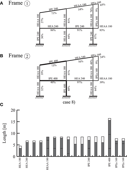
Figure 10. Optimal design for case 8: (A,B) optimal cross-sections for frames ① and ② respectively, (C) cutting pattern of reused stock elements.
Globally optimum assignment solutions for frames ① and ② in case (2) are obtained in 25 and 80 s, respectively. Instead, when employing (A) for both frames simultaneously, the best solution is obtained after 5.8 h and global optimality is proven after 16 h (case 4). In general, separating the optimization of frame ① and ② reduces computation times significantly yet it produces solutions that are only marginally worse compared to the case when frame ① and ② are optimized simultaneously. In case (6), cutting stock optimization (B) applied to frame ② required 56 h to prove global optimality. However, a solution with 1.1% higher objective value than the global optimum has been obtained after 1,200 s. Global optimality of the solution for case (8) could not be proven within reasonable time.
This case study has shown that reusing structural elements can result in a significant reduction of embodied GHG emissions. Considering the whole office building (secondary beams as well as two times frames ① and ②), embodied GHG emissions have been reduced from 23,520 kgCO2eq for the new steel case to 15,210 kgCO2eq through cutting stock optimization (B) [solution denoted as “(L2) + (8) + (8)”] in bottom row of Table 5. However, the computation time to obtain this solution may be too long in practice and global optimality may not be proven. An alternative solution denoted as “(L2) + (3) + (3)” (penultimate row of Table 5) was obtained after only 106 s and embodies 15,810 kgCO2eq, which is only 4% higher than that of the former case.
Discussion
Best results in terms of embodied GHG emissions are obtained through cutting stock optimization (B) subject to structural constraints. Assignment optimization (A) and subsequent application of cutting stock optimization produces solutions that have a slightly higher objective value (+9% and +4% for the case studies of sections Three-Bay-Three-Story Frame and Office Building, respectively) but requires significantly less computation time. Compared to stock-constraint formulations for trusses (Brütting et al., 2018), the formulation for frames involves a significantly higher number of continuous state variables (rotations and bending moments) and constraints (equilibrium, compatibility, stress and deflection limits along beams). This causes an increase of computation time compared to truss case studies of similar scale presented in previous work.
Similar to the findings by Van Mellaert et al. (2018) with regard to sizing optimization, in the case of stock-constrained problems good upper bounds might be obtained relatively fast (<1 h) but proving global optimality takes much longer. Future research could target the formulation of tighter continuous relaxations, for instance by extending existing general methods for cutting stock problems (Delorme et al., 2016) to structural optimization.
The optimization of the secondary beams in section Office Building has shown that when analytical expressions for stress and deflection limits are available, no state variables need to be added to the formulation and cutting stock optimization (B) can be employed at no computational cost even for large problem sizes (Table 5).
Case studies have shown that optimization through reuse produces structures which embody significantly less GHG compared to minimum-weight solutions made of new steel. However, these findings are limited by the assumptions made in the Life Cycle Assessment (LCA) and are specific to the case studies presented in this paper. Furthermore, some processes in the assessment were neglected or assumed equivalent (section Embodied Greenhouse Gas Emissions Quantification) in both cases Reuse and Recycling. Relative savings through reuse might therefore slightly decrease when including more processes in the LCA.
With regards to structural design, the proposed optimization method only gives preliminary results. In practice, connections between elements with different cross sections may result in increased costs. Grouping of elements and constraining the assignment to elements with identical cross section as done for the case studies in this work may help to avoid such costs. More detailed considerations related to connection design could be included in future work with regard to structural optimization and LCA as well as financial cost.
The method proposed in this work could be extended to other materials, for example timber. Reused elements have been assumed to have not degraded after their first service cycle. The method could be extended to account for material degradation by reducing cross-section properties or material strength of reclaimed elements. Such reduction could be quantified through coupon testing.
Conclusion
This paper presents the formulation of structural optimization methods to design frame structures from a given stock of reclaimed elements, which is defined by cross-sections, lengths, and availability. By combining previous work on truss structures with frame optimization, this paper extends the application domain of stock-constrained structural optimization and component reuse significantly.
Two formulations for the optimal reuse of stock elements are presented: (A) the optimal assignment of individual elements to member positions, and (B) the optimal cutting of stock elements into multiple structure members. Both formulations are combined with state-of-the-art discrete structural optimization methods for frames using mixed-inter linear programming (MILP). MILP produces global optima, which allows benchmarking solutions obtained through (A) and (B) against minimum-weight structures made of new (recycled) steel. Case studies have shown that element assignment and cutting stock optimization can be applied to obtain optimal structures that satisfy design criteria (ULS and SLS) that commensurate with realistic scenarios.
In this work, the objective function is the minimization of embodied greenhouse gas (GHG) emissions. Life Cycle Assessment is employed to quantify embodied GHG for structures made of reused and new steel elements. The case studies discussed in this work show that even though frame structures made from reused elements have a higher mass and a lower element capacity utilization, they embody up to 35% less GHG with respect to structures made from new elements.
Data Availability Statement
The raw data supporting the conclusions of this article will be made available by the authors, without undue reservation, to any qualified researcher.
Disclosure
Frontiers Media Ltd. remains neutral with regard to jurisdictional claims in published maps and institutional affiliations.
Author Contributions
JB, CF, and GS set up research objectives and directions. Method implementation was carried out by JB with support of MS. JB carried out computation of case studies and wrote the first version of the paper. GS actively contributed to the writing of the final version. All authors contributed to manuscript revision, reviewed, and approved the final version.
Conflict of Interest
The authors declare that the research was conducted in the absence of any commercial or financial relationships that could be construed as a potential conflict of interest.
Acknowledgments
The authors would like to thank baubüro in situ, in particular Marc Angst, for providing reclaimed elements data useful to carry out the case studies and for granting permission to publish their records.
References
Addis, B. (2006). Building With Reclaimed Components and Materials: A Design Handbook for Reuse and Recycling. London: Earthscan.
Arora, J. S. (2000). Methods for discrete variable structural optimization. Adv. Technol. Struct. Eng. Proc. 1–8. doi: 10.1061/40492(2000)23
Arora, J. S., and Wang, Q. (2005). Review of formulations for structural and mechanical system optimization. Struct. Multidiscip. Optim. 30, 251–272. doi: 10.1007/s00158-004-0509-6
Brütting, J., Desruelle, J., Senatore, G., and Fivet, C. (2019a). Design of truss structures through reuse. Structures 18, 128–137. doi: 10.1016/j.istruc.2018.11.006
Brütting, J., Senatore, G., and Fivet, C. (2018). “Optimization formulations for the design of low embodied energy structures made from reused elements,” in Advanced Computing Strategies for Engineering, Lecture Notes in Computer Science, eds I. F. C. Smith and B. Domer (Cham: Springer), 139–163.
Brütting, J., Senatore, G., and Fivet, C. (2019b). Form follows availability - designing structures through reuse. J. Int. Assoc. Shell Spat. Struct. 60, 257–265. doi: 10.20898/j.iass.2019.202.033
Brütting, J., Senatore, G., and Fivet, C. (2019c). “Exploration of spatial structures made from reused elements and the design of optimal kits-of-parts,” in Structures and Architecture - Bridging the Gap and Crossing Borders, eds P. J. S. Cruz (London: CRC Press). doi: 10.1201/9781315229126-27
Brütting, J., Wolf, C. D., and Fivet, C. (2019d). The reuse of load-bearing components. IOP Conf. Ser. Earth Environ. Sci. 225:012025. doi: 10.1088/1755-1315/225/1/012025
Bukauskas, A., Shepherd, P., Walker, P., Sharma, B., and Bregula, J. (2017). “Form-Fitting strategies for diversity-tolerant design,” in Proceedings of the IASS Annual Symposium (Hamburg).
Camp, C., Pezeshk, S., and Cao, G. (1998). Optimized design of two-dimensional structures using a genetic algorithm. J. Struct. Eng. 124, 551–559. doi: 10.1061/(ASCE)0733-9445(1998)124:5(551)
Deb, K., and Gulati, S. (2001). Design of truss-structures for minimum weight using genetic algorithms. Finite Elem. Anal. Des. 37, 447–465. doi: 10.1016/S0168-874X(00)00057-3
Degertekin, S. O. (2008). Optimum design of steel frames using harmony search algorithm. Struct. Multidiscip. Optim. 36, 393–401. doi: 10.1007/s00158-007-0177-4
Delorme, M., Iori, M., and Martello, S. (2016). Bin packing and cutting stock problems: mathematical models and exact algorithms. Eur. J. Oper. Res. 255, 1–20. doi: 10.1016/j.ejor.2016.04.030
Fujitani, Y., and Fujii, D. (2000). “Optimum structural design of steel plane frame under the limited stocks of members,” in Proceedings of the RILEM/CIB/ISO International Symposium, Integrated Life-Cycle Design of Materials and Structures (Helsinki), 198–202.
Ghattas, O. N., and Grossmann, I. E. (1991). “MINLP and MILP strategies for discrete sizing structural optimization problems,” in Electronic Computation (Indianapolis, IN: ASCE), 197–204.
Gilmore, P. C., and Gomory, R. E. (1961). A linear programming approach to the cutting-stock problem. Oper. Res. 9, 849–859.
Gordon Engineering (1997). Demolition Energy Analysis of Office Building Structural Systems. Ottawa, ON: Athena Sustainable Materials Institute.
Gorgolewski, M. (2008). Designing with reused building components: some challenges. Build. Res. Inf. 36, 175–188. doi: 10.1080/09613210701559499
Gorgolewski, M. (2017). Resource Salvation: The Architecture of Reuse. Hoboken, NJ: John Wiley and Sons.
Iacovidou, E., and Purnell, P. (2016). Mining the physical infrastructure: opportunities, barriers and interventions in promoting structural components reuse. Sci. Total Environ. 557–558, 791–807. doi: 10.1016/j.scitotenv.2016.03.098
Johnson, D. S. (1974). Fast algorithms for bin packing. J. Comput. Syst. Sci. 8, 272–314. doi: 10.1016/S0022-0000(74)80026-7
Kanno, Y. (2016). Mixed-integer second-order cone programming for global optimization of compliance of frame structure with discrete design variables. Struct. Multidiscip. Optim. 54, 301–316. doi: 10.1007/s00158-016-1406-5
Kaveh, A., and Jahanshahi, M. (2008). Plastic limit analysis of frames using ant colony systems. Comput. Struct. 86, 1152–1163. doi: 10.1016/j.compstruc.2008.01.001
Kaveh, A., and Kalatjari, V. (2002). Genetic algorithm for discrete-sizing optimal design of trusses using the force method. Int. J. Numer. Methods Eng. 55, 55–72. doi: 10.1002/nme.483
Kripakaran, P., Hall, B., and Gupta, A. (2011). A genetic algorithm for design of moment-resisting steel frames. Struct. Multidiscip. Optim. 44, 559–574. doi: 10.1007/s00158-011-0654-7
Lagaros, N. D. (2018). The environmental and economic impact of structural optimization. Struct. Multidiscip. Optim. 58, 1751–1768. doi: 10.1007/s00158-018-1998-z
Li, L. J., Huang, Z. B., and Liu, F. (2009). A heuristic particle swarm optimization method for truss structures with discrete variables. Comput. Struct. 87, 435–443. doi: 10.1016/j.compstruc.2009.01.004
Nemhauser, G. L., and Wolsey, L. A. (1988). Integer Programming and Combinatorial Optimization. Hoboken, NJ: Wiley.
Pongiglione, M., and Calderini, C. (2016). Sustainable structural design: comprehensive literature review. J. Struct. Eng. 142:04016139. doi: 10.1061/(ASCE)ST.1943-541X.0001621
Rasmussen, M. H., and Stolpe, M. (2008). Global optimization of discrete truss topology design problems using a parallel cut-and-branch method. Comput. Struct. Structural Optim. 86, 1527–1538. doi: 10.1016/j.compstruc.2007.05.019
Rozvany, G. I. N., Bendsóe, M. P., and Kirsch, U. (1995). Layout optimization of structures. Appl. Mech. Rev. 48, 41–119. doi: 10.1115/1.3005097
Saka, M. P., and Geem, Z. W. (2013). Mathematical and metaheuristic applications in design optimization of steel frame structures: an extensive review. Math. Probl. Eng. 2013:271031. doi: 10.1155/2013/271031
Salem, O., Shahin, A., and Khalifa, Y. (2007). Minimizing cutting wastes of reinforcement steel bars using genetic algorithms and integer programming models. J. Constr. Eng. Manag. 133, 982–992. doi: 10.1061/(ASCE)0733-9364(2007)133:12(982)
Stolpe, M. (2016). Truss optimization with discrete design variables: a critical review. Struct. Multidiscip. Optim. 53, 349–374. doi: 10.1007/s00158-015-1333-x
Thanedar, P. B., and Vanderplaats, G. N. (1995). Survey of discrete variable optimization for structural design. J. Struct. Eng. 121, 301–306. doi: 10.1061/(ASCE)0733-9445(1995)121:2(301)
Tiainen, T., Mela, K., and Heinisuo, M. (2018). “Buckling length in mixed-integer linear frame optimization,” in Advances in Structural and Multidisciplinary Optimization, eds A. Schumacher, T. Vietor, S. Fiebig, K.-U. Bletzinger, K. Maute (Cham: Springer International Publishing), 1923–1936.
Tschubby (2005). Karte der Schweiz. Kantonshauptstädte Eingezeichnet. Available online at: https://commons.wikimedia.org/wiki/File:Karte_Schweiz.png (accessed March 12, 2019).
Van Mellaert, R. (2017). Optimal design of steel structures according to the Eurocodes using mixed-integer linear programming methods (Ph.D. thesis). KU Leuven, Leuven, Belgium.
Van Mellaert, R., Mela, K., Tiainen, T., Heinisuo, M., Lombaert, G., and Schevenels, M. (2018). Mixed-integer linear programming approach for global discrete sizing optimization of frame structures. Struct. Multidiscip. Optim. 57, 579–593. doi: 10.1007/s00158-017-1770-9
Vares, S., Hradil, P., Sansom, M., and Ungureanu, V. (2019). Economic potential and environmental impacts of reused steel structures. Struct. Infrastruct. Eng. 16, 750–761. doi: 10.1080/15732479.2019.1662064
Votaw, D. F., and Orden, A. (1952). “The personnel assignment problem,” in Presented at the Symposium on Linear Inequalities and Programming, SCOOP 10 (Washington, DC), 155–163.
Wyss, F., and Frischknecht, R. (2014). Umweltproduktdeklaration Offener, Warmgewalzter Stahlprofile Nach SN EN 15804. Uster.
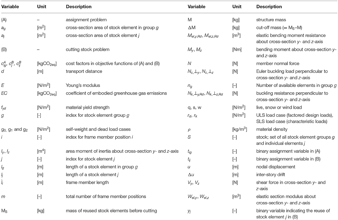
Notation
Keywords: structural optimization, frame structures, reuse, assignment problem, cutting stock problem, Life Cycle Assessment, greenhouse gas emissions
Citation: Brütting J, Senatore G, Schevenels M and Fivet C (2020) Optimum Design of Frame Structures From a Stock of Reclaimed Elements. Front. Built Environ. 6:57. doi: 10.3389/fbuil.2020.00057
Received: 13 December 2019; Accepted: 07 April 2020;
Published: 27 May 2020.
Edited by:
George C. Tsiatas, University of Patras, GreeceReviewed by:
Saeed Gholizadeh, Urmia University, IranGeorgios S. Papavasileiou, University of Wolverhampton, United Kingdom
Copyright © 2020 Brütting, Senatore, Schevenels and Fivet. This is an open-access article distributed under the terms of the Creative Commons Attribution License (CC BY). The use, distribution or reproduction in other forums is permitted, provided the original author(s) and the copyright owner(s) are credited and that the original publication in this journal is cited, in accordance with accepted academic practice. No use, distribution or reproduction is permitted which does not comply with these terms.
*Correspondence: Jan Brütting, amFuLmJydWV0dGluZ0BlcGZsLmNo
 Jan Brütting
 Gennaro Senatore
 Mattias Schevenels
 Corentin Fivet