 G. Narendra Goud
 S. Sasanka Mouli
 Balunaini Umashankar
 Saride Sireesh
 R. Madhav Madhira1
- 1Department of Civil Engineering, IIT Hyderabad, Medak, India
- 2Department of Civil Engineering, MVSREC, Hyderabad, India
- 3Department of Civil Engineering, VNR VJIET, Hyderabad, India
Design of flexible pavements is not straightforward when reinforcement materials such as geogrid, geocell, and other types of geosynthetic materials are used in pavement construction. Presently in India, elasticity theory is used to analyze strains due to wheel load applied on a multi-layered soil system through a pavement analysis program, IITPAVE, to design the unreinforced pavement section as per Indian Roads Congress guidelines (IRC-37, 2018). The improvement in the performance of geogrid-reinforced pavement with respect to unreinforced pavement can be quantified in terms of Layer Coefficient Ratio (LCR) or Traffic Benefit Ratio (TBR). In the present study, both LCR- and TBR-based approaches are proposed to design geogrid-reinforced base courses of pavements with specific goals. These specified goals included designs based on (a) reduction in consumption of aggregates and (b) reduction in the overall cost of construction of pavement reinforced with geogrids. Design charts are provided based on LCR and TBR values corresponding to selected traffic and California Bearing Ratio (CBR) of subgrades. The benefits of reinforcement in the pavement structure are found to be high when used over weak subgrades (CBR<5%). For example, a reduction in thickness of aggregate layer is found to be in the range of 28–45%. Additionally, the sustainability of geogrid-reinforced pavement is quantified by comparing the embodied carbon (EC) generated from construction of geogrid-reinforced and unreinforced pavements. EC of reinforced pavements is found to have reduced by as much as 58–85 tCO2 e/km in comparison with unreinforced pavement.
Introduction
The design of flexible pavement is complex owing to its non-homogenous nature of multiple pavement layers with different thicknesses and mechanical properties, and the wide range of loading and climatic conditions for which it is designed. There are various pavement design methods such as empirical methods, analytical methods (layered analysis), and performance-based methods (AASHTO, 1993). It is essential to incorporate new materials into the pavement design in order to optimize the material consumption and performance. The new materials such as geosynthetics have been used to reinforce pavement layers to improve their performance in critical site conditions and to sustain heavy loading situations.
Natural and freshly crushed aggregates, which have become a scarce commodity, are required in large quantities every year for construction of new pavements and rehabilitation of existing pavements. Many road project sites have no other option but to procure good-quality aggregates from far away to meet the required quantities for their construction, leading to consequent cost escalations. The reduction in the utilization of non-renewable natural resources such as aggregate is indeed required to preserve the environment. For sustainable development of transportation infrastructure, use of locally available materials in combination with engineered materials such as geosynthetics is considered one of the best solutions to preserve the dwindling natural resources. The use of geogrids offsets and thus partly reduces the aggregate requirement in the pavement layers and impart sustainability in pavement construction by lowering the carbon footprint (Morrison, 2011).
The Indian Road Congress IRC:SP:59 (2019) recently published the guidelines for the design and use of geogrids in flexible pavement applications in India. The availability of suitable design methodologies and guidelines can promote the use of geogrid reinforcement in roadways. This paper critically examines the IRC:SP:59 (2019), and proposes objective based design approaches for geogrid-reinforced pavement along with the design charts based on IRC guidelines. The reduction in thickness of the reinforced-flexible pavement structure can be achieved through two ways: (a) reduction in the thickness of the aggregate layer or (b) reduction in the thickness of bituminous layer. Present study considers the Layer Coefficient Ratios (LCR) and Traffic Benefit Ratios (TBR) that are reported worldwide in literature corresponding to different subgrade conditions. Design charts are then provided based on LCR and TBR values corresponding to selected traffic and subgrade California Bearing Ratio (CBR) values according to the two objectives specified above. Additionally, the sustainability of the proposed solution is quantified in terms of embodied carbon (EC) values of materials utilized. Thus, an attempt is made to compute EC values for the unreinforced and geogrid-reinforced pavements with similar service life.
Background
Many researchers have studied the benefits of incorporating geogrids in the flexible pavements through large-scale model experiments (Perkins et al., 2004; Chen et al., 2009; Qian et al., 2013; Abu-Farsakh et al., 2014), full-scale accelerated pavement testing (Webster, 1993; Collin et al., 1996; Perkins and Cortez, 2005; Al-Qadi et al., 2012; Jersey et al., 2012), and numerical simulations (Bhandari, 2011; Pandey et al., 2012). However, the implementation of flexible pavement reinforcement technique is handicapped by non-availability of a detailed design to incorporate these materials in pavement layers.
Popular design methods available for reinforced pavements include (1) Giroud and Han's (2004a,b) method for unpaved roads and (2) AASHTO R50 (2009) method for geosynthetic reinforced paved roads. As paved roads have become the need of society, the discussion in this paper is restricted to only design of reinforced paved roads. AASHTO R50 (2009) provides the guidance to design geosynthetic-reinforced aggregate base course in flexible pavement structures and outlines the overall design considerations. Design steps provided in this document were initially reported by Berg et al. (2000a). The pavement design parameters typically used to quantify the benefit of geogrid reinforcement include layer coefficient ratio (LCR) and traffic benefit ratio (TBR), and are generally derived from experiments. LCR of the reinforced section may be defined as a back-calculated modifier applied to the layer coefficient of the base layer. Zhao and Foxworthy (1999) observed high layer coefficient ratios (LCR) for subgrades of low CBR (equal to 1%). Perkins (2001) found that the improvement increases with increase in geosynthetic stiffness, while it decreases with increase in the subgrade stiffness and bituminous layer thickness. TBR is defined as the ratio between the number of load cycles on a reinforced section to reach a defined failure state and the number of load cycles on an unreinforced section with the same geometry and material constituents to reach the same defined failure state. This ratio ranges from 1.2 to 50 depending on type of geogrid used, depth of geogrid placement, thickness of base provided, and strength of soil subgrade (Berg et al., 2000b).
Flexible Pavement Design Based on IRC-37 (2018)
The important components of the Mechanistic-Empirical Pavement Design method include (a) a mechanistic model to calculate the critical responses of the system and (b) empirical performance or damage models that relate the critical responses to the accumulated damage and distress levels. Two critical responses of pavement used to assess the performance are (a) horizontal tensile strain at the bottom of the bituminous layer (fatigue strains) and (b) vertical strain at the top of the subgrade (rutting strains). The cracking and rutting models in IRC: 37 are based on the findings of the research schemes of the Ministry of Road Transport & Highways (MoRTH), Government of India, under which pavement performance data were collected from all over India to evolve the fatigue and rutting criteria for pavement design using a semi-analytical approach. IITPAVE software program, developed for layered system analysis, may be adopted and different combinations of traffic and pavement layer compositions are considered to meet the performance criteria. The designer inputs the number of layers, the thicknesses of individual layers, wheel load, contact pressure, and the layer elastic properties in the program, and the outputs from the program are in terms of radial strains and compressive strains at required locations. Traffic is expressed as 80 kN standard axles. The adequacy of design is checked by comparing the computed strains from the program with the allowable strains as predicted by the fatigue and rutting models. A satisfactory pavement design can be achieved through iterative process by varying layer thicknesses or by changing the pavement layer materials. Das (2007) emphasizes the need of developing performance based/ related pavement design for various unconventional material seeking potential application in pavement construction.
In the following sections, existing unreinforced flexible pavement design procedure was extended to account for the design of geogrid-reinforced pavement design methods based on LCR and TBR values according to two objectives in hand: (a) reduction in thickness of aggregate layer (resulting in material reduction), or (b) reduction in the thickness of bituminous layer (resulting in overall cost reduction).
Geogrid-Reinforced Pavement Designs
The design of reinforced flexible pavement is similar to that of design of unreinforced pavement. However, the improved elastic modulus of the reinforced pavement layer is modified according to the LCR of the reinforced pavement layer (using IRC:SP:59, 2019). The detailed design procedures that consider geogrid benefit in terms of either LCR or TBR are provided. The LCR-based design approach (IRC:SP:59, 2019) employs IITPave software (mechanistic-empirical approach) to check the strains at critical points and revise layer thicknesses accordingly (IRC:SP:59, 2019). Studies are available in the literature on the reduction of base layer thickness with the inclusion of geogrid reinforcement in a pavement. Webster (1993) reported the results of full-scale traffic testing on geogrid reinforced flexible pavement and proposed the equivalent reinforced base layer thickness corresponding to unreinforced base layer thickness. Perkins (1999) reported results from large-scale pavement testing under cyclic loads. It has been observed that the structural contribution of a geosynthetic reinforcement in a pavement is very similar to that of a pavement section with additional base layer thickness. In the light of available performance data of the geogrid-reinforced flexible pavements, the reduction in thickness of base layer is targeted. When a reinforcement layer is introduced into a pavement layer, the overall stiffness of that particular layer increases. In LCR method, the increase in the elastic modulus of the reinforced layer is quantified by increasing the value of layer coefficient of the particular layer. However, in the case of TBR method, the increase in the serviceability of the pavement due to reinforcement is quantified using the Traffic Benefit Ratio. Then the layer thicknesses are reduced accordingly to arrive at the design life period. However, both LCR values and TBR values depends on the various factors such as stiffness of geogrid, subgrade stiffness and thickness of pavement above geogrid.
LCR-Based Design
The following steps may be adopted to design geogrid- reinforced pavement using appropriate values of design traffic, subgrade CBR, and LCR values. Steps 1 through 7 correspond to the design of unreinforced flexible pavement as per IRC-37 (2018), while Steps 8 through 11 are additional steps to be followed for the design of reinforced flexible pavement as per IRC:SP:59 (2019).
Step 1. Determine the design traffic requirements on the pavement in terms of cumulative number of million standard axles (MSA)
Step 2. Determine 90th percentile California Bearing Ratio (CBR) of the subgrade
Step 3. The resilient modulus of subgrade can be calculated from Equation (1)
where MR is the resilient modulus of subgrade soil in MPa and CBR is the California Bearing Ratio of subgrade layer in %
Step 4. Resilient modulus of subbase and base layers can be found using Equations (2) and (3). Thickness of the layers is assumed initially.
where MR_gsb is the resilient modulus of granular subbase layer in MPa, MR_sg is the resilient modulus of subgrade in MPa, and h is the thickness of the GSB layer.
where MR_gb is the resilient modulus of granular base layer in MPa, MR_gsb is the resilient modulus of granular subbase layer in MPa, and h is the thickness of the GSB layer.
Modulus value of unbound granular materials is stress dependent and since induced stresses decrease with depth, modulus values also decrease with depth. This implies that the modulus of the granular material in each layer is a function of the layer thickness and of the modulus of the under lying layer (Kuo, 1979). It may be noted from Equations (2) and (3) that the resilient modulus of base or subbase layers depend only on the thickness of these layers and resilient modulus of underlying layer but does not depend on the quality of these layers (soft aggregate/crushable aggregate/competent aggregate). This seems counter intuitive and may be an anomaly in the Equations.
Step 5. Determine the wheel load and tire pressures for which the pavement need to be designed [tire pressure usually taken as 560 kPa, which corresponds to equivalent single axle wheel load (ESAL)]
Step 6. Limiting fatigue strains at the bottom of the bitumen layer and limiting rutting strains at the top of the subgrade are calculated using Equations (4) and (5), and Equations (6) and (7) according to the percentage of reliability, respectively:
where εt is the maximum tensile strain at the bottom of the bituminous layer, Nf is the fatigue life in number of standard axles, and MR is the resilient modulus of the bituminous layer in MPa
where εv is the vertical strain in the subgrade and N is the number of cumulative standard axles
Step 7. Using IITPave software, the tensile strains at the bottom of the bitumen layer and compressive strains at the top of the subgrade in the assumed pavement section are calculated for the unreinforced pavement section by trial and error. The design of unreinforced flexible pavement is accomplished by ensuring that the fatigue and rutting strains are within the limits as computed in step 6.
Step 8. Determine the Layer Coefficients a2, a3 for granular base and subbase material from their elastic (resilient) modulus, EBS and ESB, using Equations (8) and (9) in accordance with AASHTO (1993).
where EBS is the elastic modulus of base layer in psi, and ESB is the elastic modulus of subbase layer in psi
Step 9. Layer coefficients are modified for the reinforced pavement by multiplying with the LCR to the layer in which reinforcement is provided.
Modified Layer coefficient of reinforced pavement layer,
where ai is the layer coefficient of i-th layer, and LCRi is the Layer Coefficient Ratio of i-th layer
LCR values considered in the present designs range from 1.2 to 1.4
Step 10. The improved elastic modulus of reinforced layer is obtained by back calculating it corresponding to the modified layer coefficient using Equations (8) or (9).
Step 11. The improved elastic modulus of reinforced layer is incorporated in IITPave software to obtain the revised thickness of the layers satisfying the conditions of rutting strain at the top of the subgrade and fatigue strain at the bottom of the bitumen layer within the limiting strains
TBR-Based Design
The unreinforced pavement is designed using IRC-37 (2018), guidelines and the corresponding structural number (SN) of the pavement structure is computed according to AASHTO pavement design guidelines (AASHTO, 1993). In order to design the reinforced pavement, Traffic Benefit Ratio (TBR) is used. The effect of geogrid reinforcement is quantified in terms of equivalent structural number by considering traffic to be catered by the pavement and TBR that can be obtained with selected geogrid. The equivalent structural number of the geogrid is then used to reduce the unreinforced pavement layer thicknesses to the extent of reinforcement effect. The step-by-step procedure of design of geogrid-reinforced pavement using TBR approach is as follows:
Step 1. Design the unreinforced pavement by considering subgrade soil CBR and the traffic to be catered as per the guidelines provided by IRC-37 (2018).
Step 2. Compute the total structural number (SNUR) of the unreinforced pavement structure designed in Step 1, taking into account the appropriate layer coefficients and drainage coefficients and thickness of each layer in accordance with AASHTO (1993) using Equation (11).
where ai is the layer coefficient of i-th layer, Di is the thickness of the i-th layer, and mi is the drainage coefficient of i-th layer
Step 3. Compute the SNu required over the subgrade of unreinforced pavement to cater design number of standard axle load passes (W18Unreinforced) using the following equation and substituting the appropriate values in Equation (12).
Step 4. Select an appropriate traffic benefit ratio (TBR) based on full-scale field studies or large-scale laboratory studies which represent similar field conditions and failure criteria. TBR typically ranges from 2 to 6 depending on the stiffness of the geogrid, subgrade CBR, base/subbase thickness, placement depth of geogrid, and bituminous mix layer thickness.
Step 5. Compute the number of standard axle load passes, W18Reinforced that can be allowed on the reinforced pavement structure by multiplying TBR with W18Unreinforced.
Step 6. Compute the structural number, SNr of pavement which can cater computed number of standard axle passes, W18Reinforced with reinforcement using Equation (12).
Step 7. Find the equivalent structural number of the geogrid by subtracting SNu from SNr.
Step 8. Reduce the base/ subbase layer thicknesses taking into account the equivalent structural number of the geogrid meeting minimum base/subbase layer thickness criteria and total structural number (SN) of unreinforced pavement.
Table 1 provides the scheme of pavement designs for both LCR- and TBR-based approaches. Two types of subgrades with the CBR of 3 and 5% and three types of traffic (20, 30, and 100 MSA) were chosen to observe the changes in pavement structure.
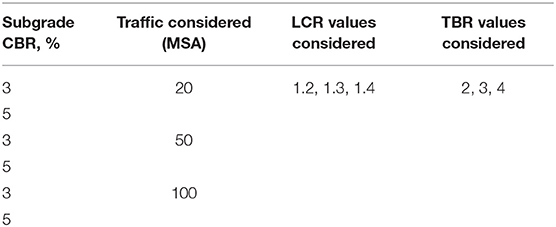
Table 1. Scheme of pavement designs using LCR and TBR approaches.
Figure 1 shows the effect of subgrade CBR on equivalent structural number of geogrid-reinforced pavement at different traffic for various TBR values. As the traffic increases, the equivalent structural number also increases. Hence, the benefit from geogrid reinforcement can be high. If the subgrade CBR is increased, the geogrid equivalent structural number decreases indicating the reduced advantage of reinforcement in pavement for stiff subgrades.
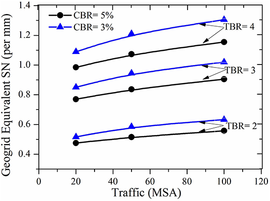
Figure 1. Variation of geogrid equivalent SN of reinforced pavement with various types of subgrades and traffic for TBR equal to 2, 3, and 4.
Objective-Based Geogrid-Reinforced Pavement Design
A client can have two objectives in a project, namely minimizing aggregate consumption in pavement layers (Objective-1) and reduction in construction cost of pavement without compromising the service life (Objective-2). Different design strategies may be adopted according to these two objectives in hand. Accordingly, designs to be adopted for each objective is given below separately.
LCR- and TBR-Based Pavement Designs With Objective-1
In this approach, the reinforced pavement composition is modified by reducing the thickness of aggregate layer (viz., Wet Mix Macadam and Granular Subbase) for a specified bituminous layer thickness. Figure 2 shows the geogrid-reinforced pavement design charts for a traffic of 100 MSA and subgrade CBRs equal to 3 and 5% at selected LCR values. Annex A illustrates the design examples for both LCR and TBR methods for a case of 50 MSA traffic, LCR = 1.4, and TBR = 3 considering Objective-1. Tables B.1.1,B.1.2 (Annex B.1) provide the summary of design thicknesses of pavement layers corresponding to a traffic of 50 and 20 MSA at selected subgrade CBR values and LCR values.
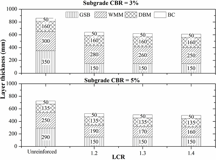
Figure 2. Design charts showing thicknesses of unreinforced and geogrid reinforced flexible pavements using LCR approach based on Objective-1 for the traffic of 100 MSA with subgrade CBRs equal to 3 and 5%.
Figure 3 shows the geogrid-reinforced pavement design charts for a traffic of 100 MSA and subgrade CBRs equal to 3 and 5% at selected TBR values. Tables C.1.1,C.1.2 (Annex C) provide the summary of design thicknesses of pavement layers corresponding to a traffic of 50 and 20 MSA at selected subgrade CBR values and TBR values.

Figure 3. Design charts showing thicknesses of unreinforced and geogrid-reinforced flexible pavements using TBR approach based on Objective-1 for the traffic of 100 MSA with subgrade CBRs equal to 3 and 5%.
The reduction in thicknesses of granular base and subbase layers in reinforced flexible pavement with respect to that of unreinforced flexible pavement is termed as aggregate layer reduction ratio (ALR). It is expressed in percentage thickness of unreinforced granular base and subbase layers.
where Dur = thickness of granular base and subbase layer in unreinforced pavement, and Dr = thickness of granular base and subbase layer in reinforced pavement. Table 2 presents the aggregate layer reductions for selected subgrade CBR, traffic, LCR, and TBR values.
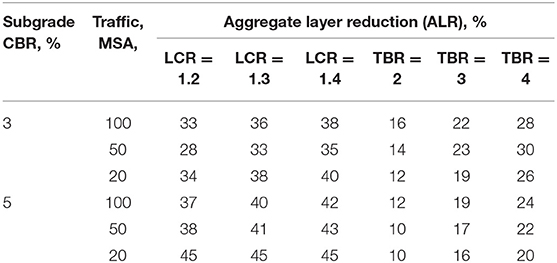
Table 2. Aggregate layer reduction for selected subgrade CBR, traffic, LCR, and TBR values.
According to the LCR design approach, the introduction of reinforcement in flexible pavement resulted in the reduction of thickness of granular base and subbase layers of reinforced pavement with respect to unreinforced pavement ranging from 28 to 40% in the case of poor subgrade (CBR = 3%), and up to 45% in the case of relatively stiff subgrades (CBR = 5%). Whereas, per the TBR design approach, the inclusion of geogrid reinforcement resulted in reduction of thickness of base and subbase layers ranging from 12 to 30% in the case of poor subgrade (CBR = 3%) and from 10 to 24% in the case of relatively stiff subgrades (CBR = 5%).
LCR- and TBR-Based Pavement Designs With Objective-2
Among all the pavement layers, bituminous layers are expensive compared to the other layers. Hence, under this objective, the thicknesses of DBM and BC layers are to be reduced in order to economize the reinforced pavement design. Figure 4 shows the geogrid-reinforced pavement design charts for a traffic of 100 MSA and subgrade CBRs of 3 and 5% at selected LCR values. Tables B.2.1,B.2.2 in Annex B.2 provide the summary of design thicknesses of pavement layers corresponding to 50 and 20 MSA at selected subgrade CBR values and LCR values.
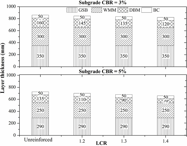
Figure 4. Design charts showing thicknesses of unreinforced and geogrid reinforced flexible pavements using LCR approach based on Objective-2 for the traffic of 100 MSA with subgrade CBRs equal to 3 and 5%.
Figure 5 shows the geogrid-reinforced pavement design charts for a traffic of 100 MSA and subgrade CBRs of 3 and 5% at selected TBR values. Tables C.2.1,C.2.2 in Annex C.2 provide the summary of design thicknesses of pavement layers corresponding to a traffic of 50 and 20 MSA at selected subgrade CBR values and TBR values.
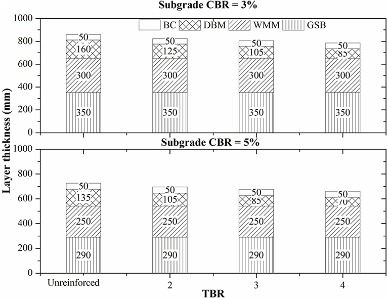
Figure 5. Design charts showing thicknesses of unreinforced and geogrid-reinforced flexible pavements using TBR approach based on Objective-2 for the traffic of 100 MSA with subgrade CBRs equal to 3 and 5%.
The reduction in bituminous layer thickness of reinforced flexible pavement with respect to that of unreinforced flexible pavement with the same design criteria may be defined as bituminous layer reduction ratio (BLR). It is expressed in percentage thickness of unreinforced bituminous layers.
where Bur = thickness of bituminous layer in unreinforced pavement, and Br = thickness of bituminous layer in reinforced pavement.
Table 3 presents the bituminous layer reductions for selected subgrade CBR, traffic, LCR, and TBR values.
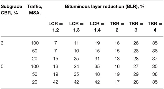
Table 3. Bituminous layer reduction for selected subgrade CBR, traffic, LCR, and TBR values.
According to the LCR design approach, the reduction in thickness of bituminous layer ranges from 7 to 31% in case of poor subgrade (CBR = 3%) and from 13 to 48% in case of relatively stiff subgrades (CBR 5%). Whereas, asper the TBR design approach, the reduction in thickness of bituminous layer ranges from 16 to 37% in case of poor subgrade (CBR = 3%) and from 15 to 29% in case of relatively stiff subgrades (CBR = 5%).
Sustainability of Geogrid-Reinforced Pavement: Counting Carbon
In order to achieve sustainable development goals (SDGs) set by the United Nations program Transforming Our World: The 2030 Agenda for Sustainable Development UN [United Nations] (United Nations General Assembly, 2015), it is essential to analyze the sustainability of alternate options in terms of design methods, construction techniques, and materials used to build the infrastructure. Carbon footprint is a measure of total green-house gases (GHG) emissions caused directly and indirectly by a person, organization, event or product. It is measured in ton of carbon dioxide equivalent (tCO2 e). The carbon footprint covers emissions over the whole life of a product, service, or solution (i.e., including the construction solution). Comparison of calculated carbon footprints for alternative solutions can be used to select the most “sustainable” option (Dixon et al., 2016). Embodied carbon (EC) is an indicator of cumulative carbon emissions used in the solution adopted. EC of a material can be defined as the amount of CO2 emissions released in the extraction, manufacture, and transport of the material. It is calculated in ton of CO2 per mass of construction material produced (e.g., tCO2/t) (Huang et al., 2016).
Owing to use of geogrids in pavements, a reduction in aggregate utilization directly results in reduction in material handling and emission of green-house gases (GHG) leading to decrease in carbon footprint. However, there will be an increase in carbon footprint due to the introduction of geogrid. If the net carbon footprint is reduced, the proposed pavement design solution with geogrid reinforcement and reduced thickness of pavement layers makes it a sustainable pavement for the same service life as that of conventional pavement.
The carbon emission quantification may be done within the limits of four stages of material processing and utilization: material manufacture, transportation, construction, and disposal (Huang et al., 2016). In the present case, EC values from cradle to gate were considered, which takes into account the extraction and manufacture of pavement construction material. Transportation of material to construction site is site specific and hence it was not accounted for in the present study. Table 4 presents unit EC values reported in literature for extraction and manufacturing stages of selected pavement material.
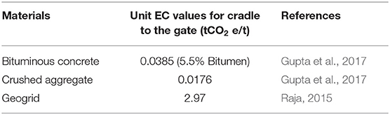
Table 4. Unit EC values for selected materials from the literature.
Unreinforced pavement section with subgrade CBR equal to 3, 5, and 10%, and catering to a traffic of 20, 50, and 100 MSA, and reinforced sections with LCR of 1.2, 1.3, and 1.4 were considered to compare EC values of the pavement materials. In the case of geogrid-reinforced pavements, only aggregate layer reduction was considered. Based on laboratory testing, the densities of bituminous mix and aggregate mix were found to be equal to 2.450 and 2.314 ton/m3, and geogrid mass as 0.0004 ton/m2. The calculation was carried out for a two-lane road of surface width equal to 7.5 m considering 1 km stretch. As followed in the construction of pavement layers, the width of lower pavement layers was increased by two times the thickness of top layer to accommodate the construction of top layer. Annex D provides the detailed procedure of computation of EC values for unreinforced and geogrid-reinforced flexible pavement. Tables 5, 6 present the pavement crust details and EC values for unreinforced and geogrid-reinforced pavements with only granular layer thickness reduction, respectively.
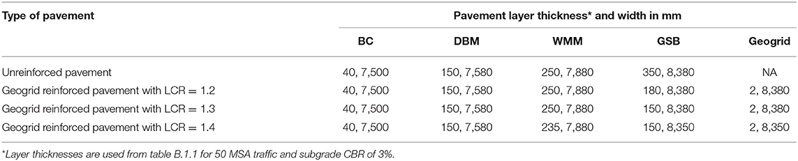
Table 5. Pavement layer thickness and width details for unreinforced and geogrid-reinforced pavements with granular layer reduction in reinforced cases.
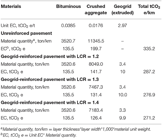
Table 6. EC values for unreinforced and reinforced pavements with granular layer reduction in reinforced cases.
Figure 6 shows the variation of EC values with subgrade CBR for unreinforced and geogrid-reinforced pavement structures corresponding to a traffic of 50 MSA and for selected LCR range. It was observed that the EC value reduces with increase in subgrade CBR. The pavement with softer subgrade (3% CBR) requires more pavement material, hence higher EC value were observed compared to the pavement with stiffer subgrade (CBR = 10%). The geogrid-reinforced pavement yielded lower EC values than unreinforced pavement for various LCR values and subgrade CBR values. Figure 7 presents the variation of EC values with traffic for different subgrades and LCR values of geogrid-reinforced pavements. It indicates that EC values decrease with increase in traffic levels. In addition, for a given traffic level and subgrade, the EC value increases with a decrease in LCR value. Figure 8 shows the variation of reduction in EC with traffic for a subgrade CBR of 5%. The reduction in EC of geogrid-reinforced pavement ranges from 58 to 85 tCO2 e/km for the traffic range of 20–100 MSA and LCR of 1.2–1.4. It is observed that reduction in EC is more (74–85 tCO2 e/mm) for the traffic of 20 MSA compared to the traffic of 100 MSA (58–68 tCO2 e/Km).
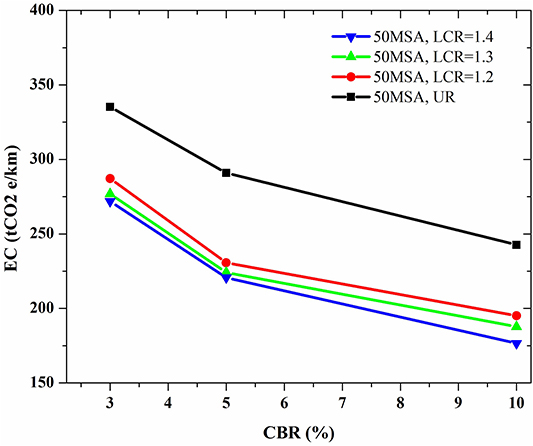
Figure 6. Variation of EC values with subgrade CBR for unreinforced and geogrid reinforced pavement structures that cater to a traffic of 50 MSA.
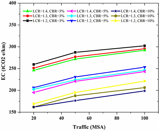
Figure 7. Variation of EC values with traffic for different subgrades and LCR values of geogrid reinforced pavements.
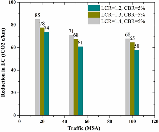
Figure 8. Variation of reduction in EC with traffic for a subgrade CBR of 5%.
Additionally, the construction cost of reinforced pavements can be reduced due to the reduced material handling, processing, and consumption in comparison with unreinforced pavements. Hence, a solution that considers reinforcement of flexible pavement with geogrid can be a sustainable option.
Conclusions and Comments
In this study, LCR- and TBR-based approaches are adopted to design geogrid-reinforced flexible pavements. The design of pavement structure is carried out according to two objectives in mind: (a) minimizing the use of aggregates (in base and subbase layers) and (b) minimizing the overall cost of construction of the pavement.
Depending on the objective in hand, owing to the introduction of geogrid-reinforcement in flexible pavement, the thickness of granular base and subbase layers of reinforced pavement can be reduced by at least 10% to as high as 45% for subgrades with CBR <5%. Similarly, it is possible to reduce the thickness of the bituminous layer of geogrid-reinforced pavement by at least 7% to as high as 48% with respect to unreinforced pavement when the subgrade CBR is <5%. Designs have been carried out for subgrades with different CBR values (3 and 5%) and traffic (20, 50, and 100 MSA). Additionally, the sustainability of geogrid-reinforced pavements is quantified. The EC values are found to have reduced in the range of 58–85 tCO2 e/Km for geogrid-reinforced cases compared to an unreinforced pavement.
The paper thus highlights several well-known advantages of using geosynthetics in pavements, such as (i) saving in money and material, (ii) increased life of pavement with consequent reduction in annual maintenance costs, and (iii) lesser construction time, along with hidden benefits such as less carbon footprint, improved riding quality, and less vehicle maintenance.
Data Availability Statement
All datasets generated for this study are included in the article/Supplementary Material.
Author Contributions
BU, SS, and RM conceived the presented idea of geogrid reinforced pavement design method for Indian conditions and sustainability aspects of geogrid reinforced pavements and verified the methods. GG and SM developed the method and performed the computations based on suggestions from BU, SS, and RM. In brief, all authors have discussed the findings and contributed to the final manuscript.
Funding
This work was conducted as part of sponsored research by National Highways Authority of India (NHAI). Grant Number: NHAI/TIC/R&D/108/2016.
Conflict of Interest
The authors declare that the research was conducted in the absence of any commercial or financial relationships that could be construed as a potential conflict of interest.
Supplementary Material
The Supplementary Material for this article can be found online at: https://www.frontiersin.org/articles/10.3389/fbuil.2020.00071/full#supplementary-material
References
AASHTO R50 (2009). Standard Practice for Geosynthetic Reinforcement of the Aggregate Base Course of Flexible Pavement Structures. Washington, DC: American Association of Highway and Transportation Officials.
Abu-Farsakh, M. Y., Akond, I., and Chen, Q. (2014). “Evaluation of performance of geosynthetic-reinforced unpaved roads using plate load tests,” in 93rd TRB Annual Meeting (Washington, DC: Transportation Research Board), 901–912.
Al-Qadi, I. L., Dessouky, S. H., Kwon, J., and Tutumluer, E. (2012). Geogrid-reinforced low-volume flexible pavements : pavement response and geogrid optimal location. ASCE J. Transp. Eng. 138, 1083–1090. doi: 10.1061/(ASCE)TE.1943-5436.0000409
Berg, R. R., Christopher, B. R., and Perkins, S. W. (2000a). Geosynthetic Reinforcement of the Aggregate Base/Subbase Courses of Pavement Structures. Roseville, CA.
Berg, R. R., Christopher, B. R., and Perkins, S. W. (2000b). Geosynthetic Reinforcement of the Aggregate Base Course of Flexible Pavement Structures. GMA White Paper II (Roseville, MN: Geosynthetic Materials Association), 130.
Bhandari, A. (2011). Micromechanical Analysis of Geosynthetic-Soil Interaction under Cyclic Loading. Lawrence, KS: University of Kansas School of Engineering.
Chen, Q., Abu-Farsakh, M. Y., and Tao, M. (2009). Laboratory evaluation of geogrid base reinforcement and corresponding instrumentation program. Geotech. Test. J. 32, 516–525. doi: 10.1520/GTJ102277
Collin, J. G., Kinney, T. C., and Fu, X. (1996). Full scale highway load test of flexible pavement systems with geogrid reinforced base courses. Geosynth. Int. 3, 537–549. doi: 10.1680/gein.3.0074
Das, A. (2007). “Principles of Bituminous Pavement Design and the Recent Trends,” in Short Term Course on Pavement Engineering with Geosynthetics : Looking Ahead. Kanpur: IIT Delhi.
Dixon, N., Raja, J., Fowmes, G., and Frost, M. (2016). “Sustainability aspects of using geotextiles,” in Geotextiles: From Design to Applications (Loughborough: Woodhead Publishing Elsevier), 577–596.
Giroud, J. P., and Han, J. (2004a). Design method for geogrid-reinforced unpaved roads. I. development of design method. J. Geotechnical Geoenviron. Eng. 130, 775–786. doi: 10.1061/(ASCE)1090-0241(2004)130:8(775)
Giroud, J. P., and Han, J. (2004b). Design method for geogrid-reinforced unpaved Roads. II. calibration and applications. J. Geotechnical Geoenviron. Eng. 130, 787–797. doi: 10.1061/(ASCE)1090-0241(2004)130:8(787)
Gupta, G., Sood, H., and Gupta, P. K. (2017). “Life-cycle cost analysis of brick kiln dust stabilized perpetual pavements for lowering greenhouse gas emissions in India,” in Urbanization Challenges in Emerging Economies (New Delhi: ASCE), 377–390.
Huang, Y., Ning, Y., Zhang, T., and Wu, J. (2016). Measuring carbon emissions of pavement construction in China. Sustainability 8:723. doi: 10.3390/su8080723
IRC:SP:59 (2019). Guidelines for Use of Geosynthetics in Road Pavements and Associated Works. 1st Rev. New Delhi: Indian Roads Congress.
IRC-37 (2018). Guidelines for the Design of Flexible Pavements. New Delhi: Indian Roads Congress-New Delhi.
Jersey, S. R., Tingle, J. S., Norwood, G. J., Kwon, J., and Wayne, M. H. (2012). Full-Scale Evaluation of Geogrid Reinforced Thin Flexible Pavements. Pittsburgh, PA: Transportation Research Record.
Kuo, S. S. (1979). Development of Base Layer Thickness Equivalency. Research Project 68 E-42 Research Report No. R-1119. Michigan Department of Transportation, Lansing, MI.
Morrison, B. (2011). “Geosynthetics as a component of sustainability in pavement structure design for arterial roadways,” in 2011 Conference and Exhibition of the Transportation Association of Canada (Edmonton, AB: Alberts), 13. Available online at: http://conf.tac-atc.ca/english/annualconference/tac2011/docs/sm2/morrison.pdf
Pandey, S., Rao, K. R., and Tiwari, D. (2012). “Effect of geogrid reinforcement on critical responses of bituminous pavements,” in ARRB Conference, 25th. (Perth, WA), 1–17. Available online at: http://trid.trb.org/view.aspx?id=1224083 (accessed January 25, 2014).
Perkins, S. W. (1999). Mechanical response of geosynthetic-reinforced flexible pavements. Geosynth. Int. 6, 347–382. doi: 10.1680/gein.6.0157
Perkins, S. W. (2001). Numerical Modeling of Geosynthetic Reinforced Flexible Pavements. Bozeman, MT: Montana State University.
Perkins, S. W., Christopher, B. R., Eli, C. L., Eiksund, G. R., Hoff, I., Schwartz, C. W., et al. (2004). Development of Design Methods for Geosynthetic Reinforced Flexible Pavements. Available online at: http://www.westerntransportationinstitute.org/documents/reports/426202_Final_Report.pdf (accessed January 25, 2014).
Perkins, S. W., and Cortez, E. R. (2005). Evaluation of base-reinforced pavements using a heavy vehicle simulator. Geosynth. Int. 12, 86–98. doi: 10.1680/gein.2005.12.2.86
Qian, Y., Han, J., Pokharel, S. K., and Parsons, R. L. (2013). Performance of triangular aperture geogrid-reinforced base courses over weak subgrade under cyclic loading. J. Mater. Civil Eng. 25, 1013–1021. doi: 10.1061/(ASCE)MT.1943-5533.0000577
Raja, J. M. (2015). Reducing the Environmental Impact of Construction Through Use of Geosynthetics. Loughborough: Loughborough University.
United Nations General Assembly (2015). Transforming Our World: The 2030 Agenda for Sustainable Development. A/RES/70/1, 16301 (New York, NY: United Nations General Assembly), 13–14.
Webster, S. L. (1993). Geogrid Reinforced Base Courses for Flexible Pavements for Light Aircraft : Test Section Construction, Behavior Under Traffic, Laboratory Tests and Design Criteria. Vicksburg, MI: Federal Aviation Administration.
Zhao, A., and Foxworthy, P. T. (1999). Geogrid Reinforcement of Flexible Pavements: A Practical Perspective. Avaiable online at: http://trid.trb.org/view.aspx?id=503862
Notations
MR is the resilient modulus
CBR is the California Bearing Ratio of subgrade layer in %
LCR is the Layer Coefficient Ratio
TBR is the Traffic Benefit Ratio
MR_gsb is the resilient modulus of granular subbase layer
MR_sg is the resilient modulus of subgrade
MR_gb is the resilient modulus of granular base layer
Nf is the fatigue life in number of standard axles
εt is the maximum tensile strain at the bottom of the bituminous layer
N is the number of cumulative standard axles
εv is the vertical strain in the subgrade
EBS is the elastic modulus of base layer
ESB is the elastic modulus of subbase layer
ai is the layer coefficient of i-th layer
LCRi is the Layer Coefficient Ratio of i-th layer
is the modified layer coefficient of i-th layer
SNUR is the structural number of the unreinforced pavement
Di is the thickness of the i-th layer
m2 is the drainage coefficient of base layer
m3 is the drainage coefficient of subbase layer
SNu is the structural number required
W18Ur is the number of standard axle load passes allowable on unreinforced pavement
ZR is the Standard normal deviate
S0 is the overall standard deviation for flexible pavement
PSI is the change in present serviceability index
W18Reinforced is the number of standard axle load passes allowable on reinforced pavement
SNr is the structural number of the reinforced pavement
Dur is the thickness of granular base and subbase layer in unreinforced pavement
Dr is the thickness of granular base and subbase layer in reinforced pavement
Bur is the thickness of bituminous layer in unreinforced pavement
Br is the thickness of bituminous layer in reinforced pavement
Keywords: geogrid-reinforced pavement, pavement design, base reinforcement, layer coefficient ratio (LCR), traffic benefit ratio (TBR), embodied carbon, sustainability
Citation: Goud GN, Mouli SS, Umashankar B, Sireesh S and Madhira RM (2020) Design and Sustainability Aspects of Geogrid-Reinforced Flexible Pavements—An Indian Perspective. Front. Built Environ. 6:71. doi: 10.3389/fbuil.2020.00071
Received: 29 October 2019; Accepted: 27 April 2020;
Published: 16 June 2020.
Edited by:
Castorina Silva Vieira, University of Porto, PortugalReviewed by:
Amarnath M. Hegde, Indian Institute of Technology Patna, IndiaSujit Kumar Dash, Indian Institute of Technology Kharagpur, India
Copyright © 2020 Goud, Mouli, Umashankar, Sireesh and Madhira. This is an open-access article distributed under the terms of the Creative Commons Attribution License (CC BY). The use, distribution or reproduction in other forums is permitted, provided the original author(s) and the copyright owner(s) are credited and that the original publication in this journal is cited, in accordance with accepted academic practice. No use, distribution or reproduction is permitted which does not comply with these terms.
*Correspondence: Balunaini Umashankar, YnVtYUBjZS5paXRoLmFjLmlu