- 1Politecnico di Bari, DICAR, Bari, Italy
- 2Politecnico di Bari, DICATECh, Bari, Italy
- 3Department of Structural, Geotechnical and Building Engineering, Politecnico di Torino, Turin, Italy
- 4National Technical University of Athens, Zografou Campus, Athens, Greece
Arches represent a structural system adopted in construction practice for thousand years, and they are still widely adopted if large spans have to be covered. The structural efficiency of arches principally depends on the minimization of the eccentricity of the pressure curve, which allow us to reduce their structural weight. Despite the millenarian use and a very abundant literature, there is still scope for design optimization of arches. This study is framed within this context and is focused on plane circular arches under uniformly distributed vertical load and self-weight. The arches are elastically clamped at both end sections. A semianalytical approach is developed to minimize the volume, with the aim of determining the fundamental mechanical parameters governing the optimal design. Finally, the results are charted to allow their use in a design process.
Introduction
Arches are inherently efficient structures; they are capable to transfer loads from the superstructure to the foundations (Wilson, 2005) with low structural weight. If properly shaped, they become the optimal solution to cross large spans and transfer high loads. Structural efficiency depends on the predominance of axial internal forces with low eccentricity (Allen and Zalewski, 2009; Marano et al., 2014; Wang and Wang, 2015): in this circumstance, smaller cross-sections can be used with respect to beams. Contrarily, large eccentricities of axial internal forces or large shear stresses lead to uneconomical design, subexploitation of building materials, and unnecessary self-weight (Billington, 1982; Gohnert et al., 2013). Further design economy can be achieved via a more demanding overall shape optimization, aimed at satisfying specific objectives, and constraints. In many cases, structural volume is minimized (Fiore et al., 2016; Greco et al., 2016).
From the data of 55 arch bridges built during the twentieth century reported in Salonga and Gauvreau (2014), several empirical lessons may be learned. The first one is that (longer span) concrete arches require, per unit length, higher material quantities as compared to (shorter span) post tensioned concrete girder bridges. This is an expected result, at least since arches are curved, whereas beams are not and, moreover, post tensioned concrete girders are not usable on large spans. The second lesson is that, for long span arch bridges, arch self-weight is about half of the total vertical load. Both lessons motivate the search for optimal (less material consuming) solutions.
Traditionally, it is since the seventeenth century that Galileo and next Hooke first approached the hanged chain problem, but more accurate solutions, published on Acta Eruditorum, are due to Bernoulli, Leibniz, and Huygens. Since then, the catenary curve has been addressed as optimal solution for compressive arch ribs under directly applied loads or for suspended cables in tension. Catenary arches show properties of pure compression, without bending moment or shear stress. A chain suspended between two points will form this curve, which is routinely used for arches and sometimes for shells (although this is not fully correct due to bidimensional stiffness). It is worth to remember that Hooke, as reported by Heyman, was the first experimentalist; he introduced the concept of inverted catenary as optimal arch form. Significant support was also given by Gaudí, Otto, and Isler during the nineteenth and twentieth century. These traditional studies focused on the hanged chain problem mainly regarding masonry arches in which opening of joints between vassoirs and sliding at interfaces must be avoided.
Another more recent approach is focused on the search of the optimal shape of arches modeled as elastic structures. In this context, a very interesting study on moment-less arches was proposed by Lewis (2016). In his mathematical model, a prediction on a simply supported arch rib shape is presented. Both arch self-weight and a uniformly distributed load are included in the analysis in order to show which geometry, among parabolic or catenary arch, is the most suitable one. Results show that the catenary arch shape produces lower stresses.
Another very recent analytical study about arch configuration is due to Osserman (2010); he clarifies in a precise and mathematical fashion the motivations of the Gateway Arch shape in St. Louis.
A challenging view on these results can also be found in Tyas et al. (2011), where it is proved, by numerical evidence, that a parabolic funicular is not necessarily the optimal structural form to carry a uniform load between fixed supports; thus, an explicit analytical expression for geometry and stress is proposed in order to design suitable truss systems emerging from the supports and thus obtain a global optimization.
A fresh look upon optimization approach is also presented in the study by Vanderplaats and Han (1990), where an optimization technique based on an iterative force approximation method is combined with a finite-element technique to obtain a minimum arch volume, by assuming variable cross-section. Further studies have been performed, for both buildings and bridges, in D'Ambrosio et al. (2009), Fiore et al. (2016), Gilbert and Tyas (2003), Greco et al. (2016) and Trentadue and Quaranta (2013).
Moreover, in the last years, analytical investigations on arches have been mostly finalized to the prediction of buckling load (Liu et al., 2017; Li and Zheng, 2019; Zhang et al., 2019).
Within this framework, this paper is focused on the optimal design of an elastic plane circular arch having fixed span L, uniform cross-section, and subjected to a uniform vertical load and to its self-weight. It is assumed that the only non-null deformation is the bending curvature. A novel semianalytical approach is developed to minimize the volume. The obtained results allow us to highlight the main mechanical parameters governing this optimal design problem and provide useful strategies for predesign purposes. Practical analytical results to optimize arch predesign, like the ones achieved in this research, are missing in the literature.
A further novelty of this study is in the constraint conditions considered at the arch end sections, which are elastically clamped, thus accounting for all possible real cases. In fact, previous analytical studies on the same topic were strictly focused on simply supported or clamped end arches, resulting it to be so framed in a less general context (Marano et al., 2014, 2018; Trentadue et al., 2018, 2019).
Problem Statement
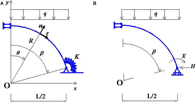
Figure 1A shows the static scheme of the right half of a circular arch of radius R, in which ϑ is the colatitude of a generic section and β the colatitude of the end section.
As already stated, intermediate conditions between hinged and clamped supports are herein considered, and bending springs of stiffness K are applied at both end sections.
The arch has a uniform cross-section area A, is made up of a homogeneous material with specific gravity weight γ, and is subjected to its self-weight and to a uniformly distributed vertical load for unit horizontal length q. Thus, the tangent load pτ and normal load pn for unit length of arch are given by
where the unit vectors n and τ are shown in Figure 1A, while qcosθ is the applied vertical load for unit length of arch. The equilibrium equations can be written as
where s = θR, N is the axial internal force, T is the shear internal force, and M is the bending moment.
Together with the above equations, the following boundary conditions must be fulfilled
where X and H are the horizontal thrust and the negative bending moment at the end sections, which will be considered redundant forces. The following dimensionless mechanical variables are now introduced:
together with the geometric relation
Equations (1–5) allow to derive the dimensionless internal forces n, t, and the dimensionless bending moment m as follows
Next, to determine the dimensionless redundant forces x and h, the force method is applied. As already stated, it is assumed that the bending curvature κ is the only non-null deformation in the arch, determined as
The primary structure is shown in Figure 1B, where the compatibility conditions ux(B) = 0 and α(B) + X/k = 0 are associated to it. Here, ux(B) and α(B) are the horizontal displacement and the rotation at the end section B.
Then, by means of virtual force theorem, the two above compatibility conditions lead to the system of two simultaneous equations:
where k = KL/EJ is the dimensionless stiffness of the springs; m is given by Equation (6c); mh is the dimensionless bending moment due to a unit thrust and mx = –1. The dimensionless redundant forces x and h are thus determined by solving Equation (8):
Optimal Solution
The optimal shape that minimizes the arch volume is herein searched. In each section, the stress under axial-bending condition must satisfy the constraint
where W is the section modulus and fd is the design strength of the material, while the dimensionless axial force n and the dimensionless bending moment m are given by Equations (6a,c). It has been considered that n is always negative.
For the structural scheme under examination, it is not possible to determine a priori in which section the stress σmax reaches its maximum. To highlight this circumstance, in Figure 2, the dimensionless moment m, obtained by Equations (6c, 9a,b), is drawn versus the colatitude θ of sections (see Figure 1). It emerges that for small values of k (in the range 1–10), the maximum bending moment is attained in a generic internal section (Figure 2A), while only for high values of k (>10), it is attained at the end sections (Figure 2B).
As a result, the cross-section area A must be determined as
where λ is a slenderness parameter, defined as λ = AL/W. For instance, in case of rectangular section, it results λ = 6L/h, where h is the height of the section.
Equation (11) cannot be directly solved since the dimensionless axial force n and the bending moment m depend on the cross-section area A through the parameter μ, defined in Equation (4). To overcome this drawback, the dimensionless internal forces are written as
and the dimensionless span η = γL/fd is introduced. This new parameter has a clear mechanical interpretation: it is the ratio between the arch span L and the height of a column made by the same material of the arch, subjected to its self-weight, in which, at the base section, the design strength fd is attained. Since μ = γA/q, the following relation holds
and Equation (11) becomes
where A(β, λ, η) is the minimum cross-section area such to satisfy the constraint σmax ≤ fd in all sections of the arch. In Equation (14), it has been considered that nq and nμ are always negative. Figure 3 plots the minimum dimensionless feasible area of a generic section
versus the section colatitude θ, for different values of the dimensionless stiffness constraints k, confirming that its maximum can be attained in any section. Finally, in view of Equation (5), the volume V can be obtained as
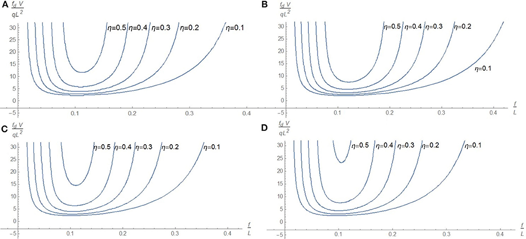
Since it is not possible to obtain a closed-form solution for Equation (16), it must be searched numerically. The obtained result is shown in Figure 4, in which the dimensionless volume fdV/qL2 versus the rise/span ratio
is drawn. A fixed value λ = 600 of the slenderness parameter is first considered, whereas the dimensionless span takes the values η = {0.1, 0.2, 0.3, 0.4, 0.5} and the dimensionless spring stiffness is set equal to k = {0, 10, 50, 500}.

Figure 3. Dimensionless area a versus the colatitude θ for β = π/4, η = 0.3 and λ = 600: (A), k = 5; (B), k = 500.

Figure 4. Dimensionless volume fdV/qL2 versus f/L for λ = 600: (A) k = 0, (B) k = 10, (C) k = 50, and (D) k = 500.
It emerges that, for all curves, the values of f /L in the range (0.1, 0.15) produce the best values of the dimensionless volume fdV/qL2. It is worth to remark that this range of optimal values of f /L is independent from the applied load q and from the span L.
The graphs in Figure 4 show that the dimensionless span η strongly influences the value of the optimal dimensionless volume and, as expected, design solutions with low dimensionless span η lead to lower values of the minimal dimensionless volume.
Therefore, η is a fundamental parameter governing the design. In particular, in view of Equation (16), the dimensionless volume tends to infinity when in a generic section it results
It can be easily shown that if Equation (18) holds, then the condition σmax = fd is immediately attained, yet for a null value of q, as effect of the self-weight only.
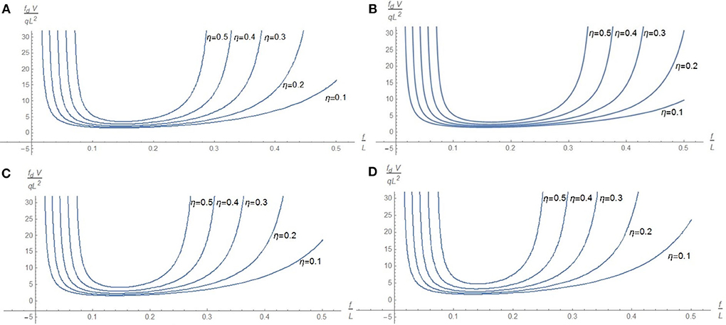
In Figure 5, the same graphs of Figure 4 are derived for λ = 200. It can be noted that design solutions with lower slenderness lead to lower values of the minimal dimensionless volume.

Figure 5. Dimensionless volume fdV/qL2 versus the rise/span ratio f /L for λ = 200: (A) k = 0, (B) k = 10, (C) k = 50, and (D) k = 500.
In conclusion, we can find a range of feasible values of the rise/span ratio f /L for each set of values of η, λ, and k. At the boundaries of this range, the dimensionless volume tends to infinity, regardless of the value of the external load q.
As it can be inferred from Figures 4, 5, the main parameter determining this range is the dimensionless span η. We recall that, by increasing the dimensionless span η, the range of feasible values for the dimensionless rise f /L narrows and the optimal dimensionless volume increases.
With regard to the influence of the dimensionless constraint stiffness k, from Figures 4, 5, it emerges that the best value of this parameter is about 10, so not corresponding neither to clamped ends nor to simply supported ends, highlighting the importance to consider a generic value of stiffness for bending spring constraints.
Based on the above graphs, the following design procedure can be proposed. First, the dimensionless span η is determined by the material properties γ, fd, and the span L. Next, the optimal values of the rise/span ratio f/L and of the dimensionless volume fdV/qL2 are evaluated by the graphs in Figures 4, 5, for assigned values of λ and k. The evaluation of the optimal volume V allows on the one side to estimate the cost of the structure and on the other to calculate the corresponding optimal cross-section dimensions. For example, in the case of rectangular cross-section, the height h and the width b could be obtained, after fixing the slenderness parameter λ, by the following relations:
where the colatitude β can be determined by the rise/span ratio f /L, solving the equation
which leads to a second-degree equation in the unknown cosβ.
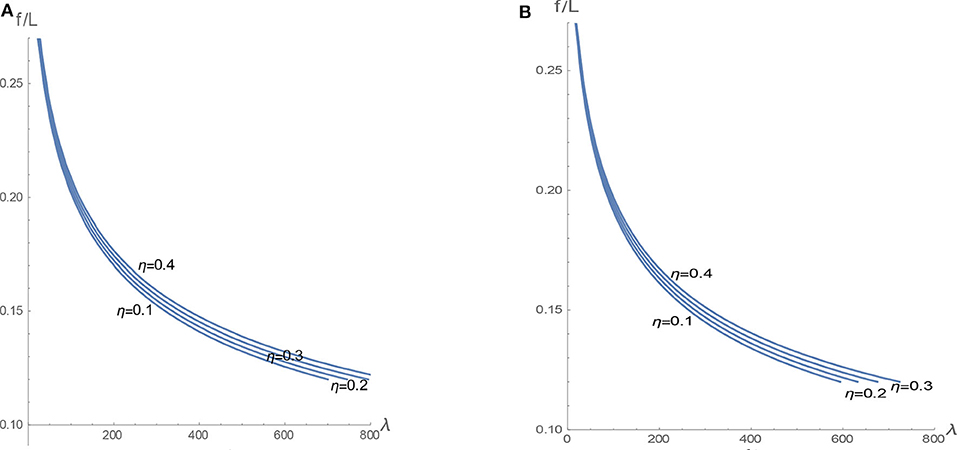
Finally, the graph in Figure 6 directly shows the optimal dimensionless rise versus λ, for different values of η, in case of simply supported ends (k = 0) and in case of nearly clamped end sections (k = 100). We can notice that the stiffness k slightly influences the optimal dimensionless rise.

Figure 6. Optimal rise/span ratio f /L versus λ for different values of η and constraints stiffness: (A) k = 0 and (B) k = 100.
Moreover, this plot can be used for practical predesign purposes: by fixing the section modulus W, the material properties, γ and fd, and the span L, first, the parameters λ and η can be calculated and then the optimal value of the dimensionless rise can be determined as by the above graph. By observing Figure 6, it emerges that the optimal values of the dimensionless rise are rather low, leading to drop arches as optimal solutions.
Conclusions
In the present study, a semianalytical solution for the optimal shape of a plane arch with bending springs at ends has been presented. Although the procedure is referred to the particular case of circular arches with uniform cross-section, it allows us to highlight the main mechanical parameters governing the solution, in particular the dimensionless span and the rise/span ratio. The obtained results show that values of the rise/span ratio in the range (0.1, 0.15), in all cases here examined, lead to a minimal weight, independently from the applied load q, from the span L, and from the other mechanical properties. Thus, it can be inferred that optimal arches are always moderately shallow. In this case, even if relevant axial internal forces are developed, the eccentricity of the pressure curves results lower than those occurring in arches with high rises, thus producing the most convenient circumstances for design.
Finally, based on the above findings, useful graphs have been provided for predesign purposes, allowing us to obtain the optimal values of rise and volume as a function of the mechanical and geometrical properties of arches. Then, the evaluation of these optimal values allows us to derive the corresponding optimal cross-section dimensions and to estimate the cost of the structure. These steps are crucial within a predesign stage.
Data Availability Statement
The datasets generated for this study are available on request to the corresponding author.
Author Contributions
FT, GM, and NL conceived the idea of the proposed study. FT, AF, and RG developed the analytical and the numerical analysis.
Conflict of Interest
The authors declare that the research was conducted in the absence of any commercial or financial relationships that could be construed as a potential conflict of interest.
Acknowledgments
This work is framed within the research project Optimization Driven Architectural Design of Structures (OptArch)−689983, H2020-MSCA-RISE-2015.
References
Allen, E., and Zalewski, W. (2009). Form and Forces: Designing Efficient, Expressive Structures. New York, NY: Wiley.
D'Ambrosio, P., de Tommasi, D., Granieri, L., and Maddalena, F. (2009). A surface energy approach to the mass reduction problem for elastic bodies. IMA J. Appl. Math. 74, 934–949. doi: 10.1093/imamat/hxp031
Fiore, A., Marano, G. C., Greco, R., and Mastromarino, E. (2016). Structural optimization of hol-low-section steel trusses by differential evolution algorithm. Int. J. Steel Struct. 16, 411–423. doi: 10.1007/s13296-016-6013-1
Gilbert, M., and Tyas, A. (2003). Layout optimization of large-scale pin-jointed frames. Eng. Comput. 20, 1044–1064. doi: 10.1108/02644400310503017
Gohnert, M., Fitchett, A., Bulovic, I., and Bhikhoo, N. (2013). Structurally efficient housing using natural forms. J. SAICE 55, 96–102.
Greco, R., Marano, G. C., and Fiore, A. (2016). Performance-cost optimization of Tuned Mass Damper under low-moderate seismic actions. Struct. Design Tall Spec. Build. 25, 1103–1122. doi: 10.1002/tal.1300
Lewis, W. J. (2016). Mathematical model of a moment-less arch. Proc. Math. Phys. Eng. Sci. 472:20160019. doi: 10.1098/rspa.2016.0019
Li, Z., and Zheng, J. (2019). Nonlinear buckling mechanism of an arch subjected to a symmetrically-placed point load. KSCE J. Civil Eng. 23, 4781–4789. doi: 10.1007/s12205-019-5152-2
Liu, A., Lu, H., Fu, J., and Pi, Y.-L. (2017). Lateral-torsional buckling of circular steel arches under arbitrary radial concentrated load. J. Struct. Eng. 143:4017129. doi: 10.1061/(ASCE)ST.1943-541X.0001858
Marano, G. C., Trentadue, F., Greco, R., Vanzi, I., and Briseghella, B. (2018). Volume/thrust optimal shape criteria for arches under static vertical loads. J. Traffic Transport. Eng. 5, 503–509. doi: 10.1016/j.jtte.2018.10.005
Marano, G. C., Trentadue, F., and Petrone, F. (2014). Optimal arch shape solution under static vertical loads. Acta Mech. 225, 679–686. doi: 10.1007/s00707-013-0985-0
Osserman, R. (2010). How the gateway arch got its shape. Nexus Netw. J. 12, 167–189. doi: 10.1007/s00004-010-0030-8
Salonga, J., and Gauvreau, P. (2014). Comparative study of the proportions, form, and efficiency of concrete arch bridges. J. Bridge Eng. 19:4013010. doi: 10.1061/(ASCE)BE.1943-5592.0000537
Trentadue, F., Fiore, A., Greco, R., de Marco, G., Sardone, L., Marano, G. C., et al. (2019). “Volume optimization of end-clamped arches,” in Proceedings of the International Fib Symposium on Conceptual Design of Struct (Madrid: Torroja Institute), 49–56.
Trentadue, F., Marano, G. C., Vanzi, I., and Breseghella, B. (2018). Optimal arches shape for single-point-supported deck bridges. Acta Mech. 229, 2291–2297. doi: 10.1007/s00707-017-2084-0
Trentadue, F., and Quaranta, G. (2013). Limit analysis of frictional block assemblies by means of fictitious associative-type contact interface laws. Int. J. Mech. Sci. 70, 140–145. doi: 10.1016/j.ijmecsci.2013.02.012
Tyas, A., Pichugin, A. V., and Gilbert, M. (2011). Optimum structure to carry a uniform load between pinned supports: exact analytical solution. Proc. R Soc. A 467, 1101–1120. doi: 10.1098/rspa.2010.0376
Vanderplaats, G. N., and Han, S. H. (1990). Arch shape optimization using force approximation methods. Struct. Optimization 2, 193–201. doi: 10.1007/BF01748223
Wang, C. Y., and Wang, C. M. (2015). Closed-form solutions for funicular cables and arches. Acta Mech. 226, 16–41. doi: 10.1007/s00707-014-1250-x
Keywords: arch, bending springs, force method, volume minimization, optimal design
Citation: Trentadue F, Fiore A, Greco R, Marano GC and Lagaros ND (2020) Optimal Design of Elastic Circular Plane Arches. Front. Built Environ. 6:74. doi: 10.3389/fbuil.2020.00074
Received: 14 February 2020; Accepted: 29 April 2020;
Published: 12 June 2020.
Edited by:
Ekrem Tufekci, Istanbul Technical University, TurkeyReviewed by:
Metin Aydogdu, Trakya University, TurkeyFrancesco Tornabene, University of Salento, Italy
Copyright © 2020 Trentadue, Fiore, Greco, Marano and Lagaros. This is an open-access article distributed under the terms of the Creative Commons Attribution License (CC BY). The use, distribution or reproduction in other forums is permitted, provided the original author(s) and the copyright owner(s) are credited and that the original publication in this journal is cited, in accordance with accepted academic practice. No use, distribution or reproduction is permitted which does not comply with these terms.
*Correspondence: Alessandra Fiore, YWxlc3NhbmRyYS5maW9yZUBwb2xpYmEuaXQ=
 Francesco Trentadue1
 Alessandra Fiore
 Rita Greco
 Giuseppe C. Marano
 Nikos D. Lagaros
