 Florian Geiger
 Jan Gade
 Malte von Scheven
 Manfred Bischoff
- Institute for Structural Mechanics, University of Stuttgart, Stuttgart, Germany
Taking advantage of adaptivity in the field of civil engineering is a subject of ongoing research. Integration of adaptive elements in load-bearing structures is already well-established in many other engineering fields, albeit mostly for different purposes than withstanding predominantly static loads. Initial investigations have demonstrated potential for substantial material and energy savings also in the field of civil engineering, especially for high-rise buildings and wide-span structures, such as roofs or bridges. Adaptive civil structures show promise in tackling current challenges arising from emissions and shortages of materials. In this study, we compare the possible minimum-weight designs for different actuator placement approaches and for different structural topologies that satisfy various constraints for high-rise buildings. We use case studies as illustrative examples to show which advantages and disadvantages can be expected from a specific design. The overarching aim is to learn how truss and beam structures should be designed to perform well as adaptive structures.
1. Introduction
To tackle today's challenges arising from extensive material consumption, waste production, and emissions, innovative solutions are needed from the building industry. Nowadays, buildings are designed to withstand occurring loads and simultaneously satisfy defined conditions by using a large amount of material, leading to a large amount of emissions and waste. For most of a building's life span, some of this material is not needed, because extreme load conditions are not permanent. The incorporation of active elements in passive structures to make the structures adaptive offers a promising way of using material more efficiently. The resulting adaptive buildings therefore consist of passive elements, controllers, sensors, and actuators, which can influence the load-bearing and deformation behavior of the whole structure. The underlying idea is to significantly reduce embodied energy in built structures by avoiding the use of material that is necessary only in a small part of the building's life span to maintain, e.g., serviceability limits. The missing structural part is compensated for by using actuation energy, which affects the critical states that are assumed to overshoot defined limits. Preliminary investigations have demonstrated potential for significant material savings in the primary structure. In times of increasing demand for sand and other scarce raw materials, adaptive structures offer a very promising approach to more sustainable buildings.
However, compared to the design of passive structures, new challenges arise in the design of adaptive structures. Influences from architecture, structural engineering, mechanical engineering, and control engineering have to be integrated in order to design an optimal adaptive structure. To bring together specialists in all these different areas, the Collaborative Research Center SFB 1244, “Adaptive Skins and Structures for the Built Environment of Tomorrow,” was initiated in 2017 at the University of Stuttgart. Application of the design concepts in realistic scenarios and buildings is being researched and tested at the interdisciplinary Collaborative Research Center. A demonstrator high-rise will also be erected on the campus of the University of Stuttgart. Details are presented in Weidner et al. (2018). Apart from the aforementioned challenges in the design of the load-bearing structure, the research center conducts work on adaptive facades and adaptivity in the field of building physics.
The first designs to include active elements in civil structures were developed in the 1960s. Zuk and Clark (1970) presented the idea of an active tendon system for controlling static deformations and manipulating internal forces, which was the origin of much work on this topic. The early approaches focused on the control of vibrations in order to maintain defined limits of serviceability and safety (e.g., Soong and Manolis, 1987). Another research focus was deployable large-span space structures (e.g., Kwan and Pellegrino, 1993). Pertinent overviews can be found in Soong and Spencer (1992), Soong (1988), Utku (1998), and Korkmaz (2011).
In the present work, design and optimization of adaptive structures are addressed. Initial approaches to optimized adaptive structures were due to Kirsch and Moses (1977), who carried out an optimization for a given beam structure with fixed actuator position to determine the minimum cross-sectional dimensions. Optimization procedures involving simultaneous optimization of the controller and the structure were introduced by Hale et al. (1985). An overview of further optimization approaches can be found in Frecker (2003). Inspired by a separation of equilibrium and compatibility equations, introduced by Kirsch and Moses (1977), Teuffel (2004) proposed a workflow for designing ultra-light adaptive structures, additionally incorporating the problem of actuator placement in adaptive truss structures. This approach was adopted by Senatore et al. (2019) and extended to an “all in one” formulation of the design of adaptive structures which included whole-life energy assessment. Additional computational improvements were also obtained, and the results have been experimentally validated by Senatore et al. (2017). In contrast to the work of Senatore et al. (2019), the present article proposes not a workflow for designing minimum-energy adaptive structures, but rather a method for learning about fundamental properties of adaptive structures. The main goal of the method is to learn which types of structures are suitable, and especially, why. Therefore, some simplifications are needed (e.g., neglecting additional masses of actuators), which are stated in our assumptions and models, to be introduced in the appropriate sections. The problem of suitable actuator placement to achieve certain goals was addressed by Kawaguchi et al. (1996) and, from a system dynamics point of view recently, by Wagner et al. (2018), among other authors. The influence of the design process of adaptive structures on adaptability, performance, and actuation energy demand was investigated by Geiger et al. (2020b) in a simple case study. Fröhlich et al. (2019) proposed a method for optimizing structures toward their efficiency, using a measure of the total energy demand as the objective function.
This paper's focus is on incorporating adaptivity into the load-bearing structure, in order to manipulate structural behavior under different loading scenarios. Given a design task for a building, including, e.g., predefined overall dimensions and other structural constraints, finding the basic concept of the structure in terms of the topological layout of the structural members and the design of the load-bearing behavior is one of the most important tasks for the structural engineer. For conventional passive structures, layout and design strategies to produce structures that are efficient, reliable, redundant, cheap, etc., are well-known. With adaptive structures, however, building upon experience gained in the design of passive structures may lead to suboptimal results. Therefore, the aim of this research is to find design criteria and guidelines to determine whether the geometry and the topological layout of an optimal passive structure will lead to an optimal adaptive structure, and to identify how efficient adaptive structures can be characterized and designed. Preliminary studies can be found in Geiger et al. (2020a), which describes an approach to actuator placement using the redundancy matrix in a forward calculation without employing an optimization algorithm. Additionally, a proof-of-concept for the idea of transforming stiffness-governed structures into strength-governed structures is presented. The term stiffness-governed means that the stiffness of the structure against displacements is design decisive for the cross-section of structural members. It is shown that when adaptivity comes into play, this is not the case. This leads to the conclusion that the normal force and hence the maximum allowable stress of the used material is decisive for the cross-section of a bar, which is a characteristic of strength-governed problems. This transformation from stiffness-governed to strength-governed makes possible a more efficient utilization of the material and thus significant savings of material. The present work extends these basic studies, first to a systematic comparison of different assemblies in terms of topology for truss structures and then to an investigation of beam structures, in order to deduce new design guidelines.
The paper is structured as follows: In section 2 the methodology for the case study, basic assumptions, and details of the modeling are presented. Section 3 presents two different adaptive structures in various configurations. The overall mass-saving potentials are computed for the different layouts, and the design ideas deduced from them are discussed.
2. Methodology
In this section, the methodology of the case study is motivated, and the necessary actuator placement, structural and actuation models, and efficient solution process are presented.
2.1. Case Study
The aim of this research is to learn how to design adaptive structures. To derive design guidelines, a case study on different adaptive structures is conducted. The results are compared and the observations discussed with regard to insights gained into the characteristics of adaptive structures. This process requires objective measures that can be used to compare different adaptive structures and to determine which design is preferable. Comparison of adaptive structures gives rise to a new class of problems in the field of structural design, and new measures have to be defined. In the present approach, different variants of adaptive structures are compared using two values, which have to be calculated for all variants. To obtain comparable results, the outer dimensions of the variants are kept constant, and identical loading scenarios and structural constraints are used. The first measure is the mass-saving potential of the adaptive structure relative to the passive structure with the same topology but without actuation; each active element is treated as the corresponding passive element. The second measure is the total mass of the adaptive structure. We do not compare the whole-life energy demand of the structures, because this would require an additional quantification of the material saving vs. the energy saving, which would entail numerous additional assumptions, such as assumptions concerning the energy mix in the following years for different countries, and is thus beyond the scope of this study, which is dedicated to structural behavior and the corresponding potential of adaptation.
Firstly, for a given topology, the minimum-weight design of the structure without actuation is compared to the minimum-weight design of the same structure using actuators. These designs for the passive and the active structures are the solutions of two non-linear optimization problems, the formulation of which may be found in section 2.4.
Secondly, for given outer dimensions (e.g., height and width) and a given application of the adaptive structure (e.g., high-rise building), different topologies are compared to generate guidelines. The comparison makes use of insights from a structural mechanics point of view in conjunction with observations, comparing the computed results. In this process, the influence of known structural properties of the investigated topologies is examined. Among other factors, the degree of static indeterminacy is investigated. Therefore, starting from a basic configuration of an exemplary structure, different variants are generated by inserting or removing elements and/or supports. This generation process is motivated by the aim to verify or falsify hypotheses, which are presented and discussed.
2.2. Structural Model
The basic assumptions and modeling aspects are presented in this subsection. In the present investigation only structures consisting of truss and beam elements are considered, and only centric linear actuators are used, e.g., hydraulic cylinders in the center of a truss or beam element. To keep the computations as simple and fast as possible, small deformations and linear elastic isotropic material behavior are assumed. For a single element e, a linear elastic material model is chosen with Young's modulus Ee, tensile strength fy,e, mass density ρe, and Poisson's ratio νe. Dynamic effects are neglected in this case study. Under these assumptions, the discrete linear time-invariant equation of motion for the problem is given by
The system stiffness matrix K ∈ ℝn×n describes the correlation of load vectors gathered column-wise in a matrix F ∈ ℝn×l and the solution vector gathered column-wise in a matrix D ∈ ℝn×l. The number of degrees of freedom in the model is represented by the variable n, and the number of load cases is represented by l. The load vector F is the sum of the vector of external forces Fext, which collects the external forces for each degree of freedom, and the vector Fact = Bu, which contains the input matrix B ∈ ℝn×m and the actuation input u ∈ ℝm×l. The number of actuators is represented by m. The load vector can therefore be expressed as a function of the actuation input, F = F(u). The system stiffness matrix K is assembled from all the element stiffness matrices, which depend on the cross-sections of the elements. Therefore, the system stiffness matrix is a function of the vector , which collects the cross-sectional areas of all elements, and of the vector i, which collects the moments of inertia of all beam elements: K = K(a, i) = K(s). The vector of design variables relating to the cross-sections is defined as s: = [a, i]T. The solution D of Equation (1) gives the structural responses for all investigated load cases, which are used for further processing.
2.3. Actuator Model
For a proper and efficient simulation of the actuation, an active beam finite element is introduced, extending the active truss finite element presented in Geiger et al. (2020b). The aim is to apply a prescribed stroke u of an actuator directly, without further pre- and post-processing steps, for beam finite elements as well. Figure 1 shows the element used. The derivation and particular modifications compared to the active truss are briefly discussed in the following. The starting point is the total potential energy functional Πtot of a plane Bernoulli beam element, given by
The total potential energy consists of both internal and external potential energy and depends on the displacement fields in the axial direction d(x) and the transverse direction w(x). The element is in equilibrium if and only if the first variation of the total potential energy, δΠtot, vanishes. The total potential energy functional has a minimum for these particular displacement fields. For the derivation we assume geometrically and materially linear behavior and that the displacement fields in the axial and transverse directions are decoupled. Therefore, the effects can be separated in the total potential energy functional:
Quantities related to energy from axial forces in the beam, including all contributions from the actuation, are labeled with superscript N, and quantities related to bending energy are labeled with superscript M. Using this functional, the derivation simplifies to the separate derivation of the active truss element as shown in Geiger et al. (2020b) using the axial force part of the internal potential energy Πint,N[d(x)]. The actuation of the element is modeled as a discontinuity in the magnitude of the applied stroke u in the axial displacement field d(x). In order to describe this jump, the element is cut into two parts, each part is modeled separately, and the connection is introduced by the additional coupling equation for displacements in the axial direction between points a and b,
as shown in Figure 1. Including the constraint equation by means of the Lagrangian multiplier λ yields the enhanced internal energy from axial forces:
The Lagrangian functional yields
After applying the same procedure as in Geiger et al. (2020b), consisting of variation and discretization using linear ansatz functions, to the axial force part, the bending part Πint,M[w(x)] can be treated separately, leading to the derivation of a passive beam element. No effects from the centric linear actuation have to be considered in this part. For further details on the derivation of the bending stiffness matrix, see e.g., Melosh (1963). For a single plane and a straight active beam element in horizontal orientation as shown in Figure 1, the derivation yields a linear system of equations at the element level:
Quantities for part 1 are labeled with subscript 1 and quantities for part 2 with subscript 2. The matrices k1,N and k2,N describe the particular elastic axial stiffness matrices, and the vectors g1,N and g2,N are the corresponding coupling vectors. The matrices k1,M and k2,M describe the elastic bending stiffness matrices for the bending action and k12,M the corresponding coupling matrix. Load and displacement vectors are separated into displacements of the two parts and the additional variables fA and u. These parameters describe the discretized Lagrangian multiplier representing the actuator force fA, which is therefore directly computed when solving the linear system of equations, and the applied stroke in the actuator u, respectively. It can be seen that there is a coupling of the bending part between the two separated element parts 1 and 2 introduced by the matrix k12,M. At the same position in the stiffness matrix for the axial part, there is no direct coupling. The coupling of the axial part is introduced by the additional condition and therefore by the vectors g1,N and g2,N. The decoupling of axial force and bending within one element may not be seen in this representation. The element stiffness matrix and the element load vector are used to assemble the global stiffness matrix K and the global load vector F. After assembly, the linear system of equations (1) can be solved for the global solution vector D.

Figure 1. Active beam element (left) and degrees of freedom to connect the element to the rest of the structure (right).
2.4. Structural Optimization
The minimum possible mass of the structure is computed by an optimization procedure using the total mass as the objective function and several non-linear constraints for displacements and stresses. Since we only look at plane examples, the feasibility of the stresses is evaluated at four particular positions of each element: at either end of the element at the upper and lower edges of the actual cross-section. To keep it simple, only nodal loads and no distributed loads are permitted, so that it is not necessary to check the stresses along the beam span. Additionally, each element in compression is checked for buckling. Therefore, Euler's critical buckling force Nb,e is computed for the element's actual cross-section, and the absolute value of its normal force Ne may not exceed this value. Assumptions on the cross-sections are necessary to keep calculations simple and the number of design variables as small as possible. In the present paper, a square hollow section (SHS) is chosen, which can be described by only two independent variables, the cross-sectional area A and the moment of inertia I. The feasibility with maximum allowable displacements is checked at predefined degrees of freedom. The maximum displacement at those chosen degrees of freedom Dc must not exceed the predefined limit.
2.4.1. Formulation of the Optimization Problem for the Passive Structure
The formulation of the resulting mass minimization problem for the passive structure reads
2.4.2. Formulation of the Optimization Problem for the Active Structure
For the active structure, additionally the input strokes for the actuators is a design variable and part of the optimization. Therefore, the optimization problem reads
2.4.3. Solution Method for the Optimization Problems
To facilitate the simulation of several load cases in an efficient way, the solution procedure was implemented in MATLAB using vectorized solutions and post-processing. An SQP implementation available in MATLAB was chosen as the optimization algorithm, which requires the gradient and the Hessian of the objective function and of the constraint functions. The gradient of the objective function is calculated analytically and passed to the optimizer, and the gradient of the constraint functions is computed using a complex-step derivative approximation as in Squire and Trapp (1998), also vectorized for all design variables.
The attractive features of this type of numerical differentiation are briefly outlined in the following. The classical forward-difference formula for computing the first derivative of a function f(x) reads
Two errors occur in the approximation of the first derivative, namely the subtraction cancellation error, from taking the difference of two similar-valued numbers f(x + h) and f(x), and the truncation error, from neglecting the part in the computation of the approximation. The step size has to be small enough to limit the truncation error but large enough to limit the error from subtraction cancellation, and it is not trivial to estimate the optimal compromise a priori. By using the complex-step derivative, the formula changes to
This method does not suffer from the subtraction cancellation error, because no subtraction is needed. The truncation error is reduced significantly, because the truncated parts are of order . In the following optimizations a step size of h = 10−10 is used, so the truncation error can be neglected. For further reading, a derivation of the formula, and numerical examples, see Martins et al. (2003). The implementation in the MATLAB environment is not subject to major changes. Only computations of absolute values or transpositions that are suitable for complex-valued scalars, vectors, and matrices have to be implemented. The approximation of the Hessian is achieved by a Broyden-Fletcher-Goldfarb-Shanno (BFGS) algorithm; see Fletcher (2013). For future work, the Hessian can also be computed using complex numbers to achieve higher accuracy than the approximation and hence faster convergence of the optimization.
3. Case Study and Discussion
The preliminary work of Geiger et al. (2020a) is used as a starting point for the formulation of hypotheses, which will be verified or falsified in two examples. Through this structured investigation, design guidelines are deduced. The preliminary work is extended to the comparison of different layouts for a truss structure in the first example and to the investigation of frame structures in the second example. In both examples, the mass savings achieved by adaptation and the minimized total masses are compared for several topological modifications of a basic structure exposed to the same load cases. Both constraints on maximum allowable stresses and constraints on maximum allowable displacements are met through active control. Failure of the actuators or of the control system is not considered in this case study.
The following assumptions hold for both examples. In all cases structural steel S235 with the following properties is chosen:
Square hollow sections with maximum outer dimensions of 0.50 × 0.50 m are used. The thickness of the walls is not limited until the box is fully filled with material, so the wall thickness is less than 0.25 m. The minimum outer edge length is fixed at 0.01 m, and the minimum wall thickness is defined as 1.0·10−6 m. Penetration of material is prevented by a further constraint that requires twice the wall thickness to be less than or equal to the edge length. An element whose cross-section reaches the lower limit of the permissible range does not change the global results because of its low stiffness and low mass, but would regularize the stiffness matrix. Recall that the goal of the study is not to propose a directly buildable adaptive structure but to learn about adaptive structures. To keep things simple, the cross-section and the material model are assumed to be constant along the element axis in passive and in active elements. Additional masses of actuators are not considered here.
3.1. Example 1: Truss Design
As the first example, a structure is chosen that is inspired by high-rise buildings. The basic structure is shown in the left diagram of Figure 2. A similar structure was investigated by Geiger et al. (2020a). In a nutshell, their findings are that stiffness-governed design problems can be transformed into strength-governed design problems by manipulating the deformation state of the structure using active elements. This was also shown in Senatore et al. (2018), for example. For statically indeterminate structures, it is shown that the additional internal forces due to internal constraints, which arise from introducing a length change of an element as actuation, can be manipulated by additional actuators. If enough additional actuators are chosen, the reduction of the additional internal forces to zero is included in the design space but is not necessarily the optimal solution. This is also known as the introduction of “impotent eigenstrain”; see Furuhashi and Mura (1979). The results of the structural optimizations show that the necessary amount of material for the primary structure can be reduced significantly. Mass-saving potentials of 65–70% are achievable by structural adaptation in such cases. Results of this magnitude were also reported by Senatore et al. (2019).
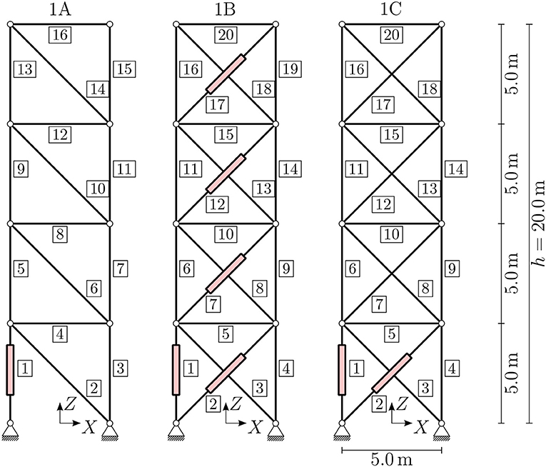
Figure 2. Example 1, truss design: investigated variants with dimensions and actuator positions.
To obtain meaningful results for the mass-saving potential, three load cases are applied; these are shown in Figure 3. Two of the load cases (red and green) can be interpreted as wind loads with constant values of ±15.0 kN/m in the X-direction along the height of the structure applied as nodal loads of ±75.0 and ±37.5 kN. The third load case (blue) is an additional load of −20.0 kN/m in the Z-direction on the horizontal floors, which results in nodal loads of 50 kN. All load cases are simulated separately. For simplicity, neither superposition nor safety factors are assumed. Additionally, the dead load of the members depending on the actual size of the cross-sectional area is considered in all load cases. For this example, horizontal deformations at all nodes, Dc = Dhoriz, are constrained to a maximum absolute value of dmax = h/500 = 20 m/500 = 0.04 m, which is a reasonable assumption in high-rise design. Additional assumptions on, for example, inter-story drift or maximum accelerations are not considered here.
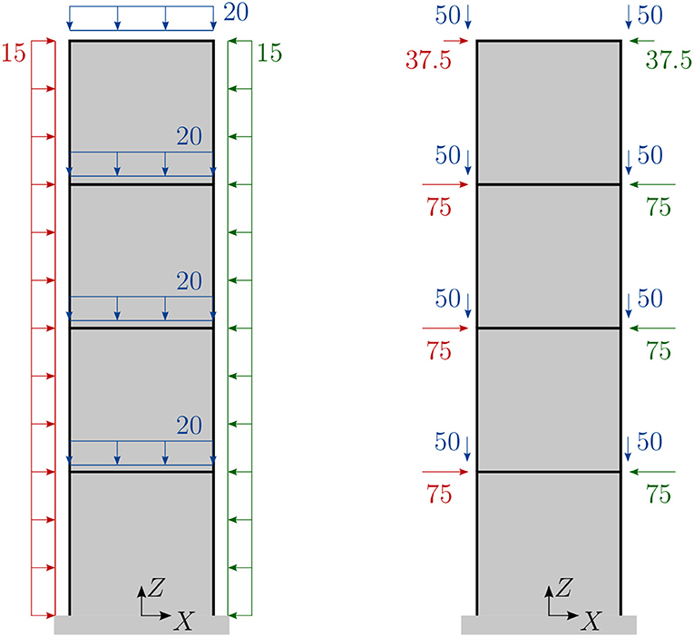
Figure 3. Example 1, truss design: three investigated load cases (red, green, and blue), with line loads in kN/m and nodal forces in kN.
The first hypothesis arises from considering the essence of the design problem at hand. The resulting structure is subject to strict constraints on the allowable displacements, which are globally decisive for the dimensions of the cross-sections. Therefore, the aim of the actuation is efficient manipulation of the displacements. This implies the first hypothesis, H1, which is formulated as: “Statically determinate structures are advantageous compared to statically indeterminate one if an adaptive structure is used to solve a stiffness-governed design problem.” The second hypothesis applies when statically indeterminate structures are investigated. The question is whether it is sufficient to enable constraint-free manipulation of the displacements, or if additional actuators are needed to enable actuation of the stress state in the structure. Therefore, the second hypothesis, H2, is formulated as: “Implementing only as many actuators as necessary to enable constraint-free manipulation of the displacements performs worse than implementing nS additional actuators to manipulate all forces arising from internal constraints.”
To test these hypotheses, several structures are compared. The basic structure, variant 1A, is shown in the left diagram of Figure 2. The figure also shows element numbers in rectangles. The truss structure is planar and consists of 16 single truss elements. Integrated actuators are shown in the figure. To determine actuator placement for the compensation of occurring deformations, methods from Wagner et al. (2018) are applied. A single actuator in element 1 is sufficient to restore about 95% of all deformations to the mean value for arbitrary load cases; therefore this actuator is chosen. As variant 1A is statically determinate, no additional actuators are necessary to control internal forces arising from internal constraints.
Variant 1B is shown in the middle diagram of Figure 2. This variant incorporates additional diagonals into the basic structure to obtain a statically indeterminate structure. Following e.g., Senatore et al. (2019), for variant 1B with static indeterminacy of degree 4, a total of four additional actuators have to be implemented to manipulate all internal forces arising from internal constraints (cf. Pellegrino and Calladine, 1986). Therefore, variant 1B has a prescribed number of five actuators, placed as shown in Figure 2 (middle). All additional elements are actuators. Variant 1C has the same topology as variant 1B but only one additional actuator to manipulate the internal forces arising from actuation. Additional information on actuator placement with the aim of compensating for introduced internal constraints can be found in Geiger et al. (2020a).
Results for the necessary mass of variant 1A in the passive state, displayed in Figure 4 and Table 1, show that in order to deal with the constraints on the horizontal displacements, the stiffness of the statically determinate passive truss structure has to be very high. If the truss were simplified to a vertical cantilever beam, the moment of inertia of the cross-section at the basement would have to be large enough to keep the deformations small. Therefore, the cross-sectional areas in the corresponding members are very large in the passive designs. Figure 5 (1A passive) shows that it is not possible to exploit the maximum possible strength in all members. The amount of mass required is determined by the required axial stiffness.
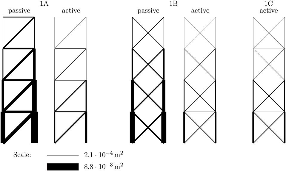
Figure 4. Example 1, truss design: optimized cross-sectional areas.
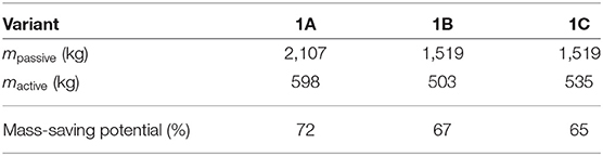
Table 1. Example 1, truss design: total masses and mass-saving potentials (additional actuator mass not considered).
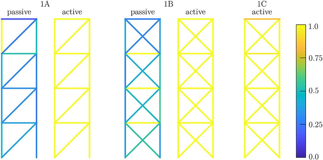
Figure 5. Example 1, truss design: maximum utilization, envelope over all load cases.
The corresponding results for the adaptive structure 1A are shown in Figure 4 (1A active) and Table 1. By incorporating the actuator in element 1, which can efficiently manipulate the horizontal displacements, it is now possible to satisfy the displacement constraints without large axial stiffness of the trusses. Therefore, the cross-sections can be utilized with their maximum strength capacity [see Figure 5 (1A active)], and this comes with a significant reduction in cross-sectional areas and mass.
Analogous observations are obtained for variant 1B. In order to check the first hypothesis, the results for the variants are compared with each other. The mass-saving potential reduces from 72% for variant 1A to 67% for variant 1B, but the total minimum mass also decreases from 598 to 503 kg, or around 15% relative to variant 1A. It can therefore be concluded that in this case hypothesis H1 does not hold. The general validity of this finding needs to be investigated in further work. Even though in both cases almost all elements are fully utilized in at least one load case, the statically indeterminate structure can carry the load to the supports using less material than the statically determinate variant. The intrinsically constraint-less actuation of the statically determinate case is not beneficial. Owing to actuation, the statically indeterminate structure also offers the possibility of constraint-free actuation. Additionally, several possible “load paths” are available to carry the load to the supports, and the manipulation of the internal constraint enables triggering of a normal force distribution that can be carried with less mass. This is not yet a universal design guideline, but it is a remarkable and somewhat counter-intuitive observation. Another notable observation is that for any actuator set, by using extra actuators starting from variant 1B no additional savings are possible. The complete actuation subspace is spanned by the chosen actuators, and any additional actuator is redundant.
Taking into account the results for variant 1C, it is found that the mass can be reduced by about 60 kg compared to variant 1A, but the minimum-weight design is not possible with only these two actuators. Figure 5 (1C active) shows that not all members are utilized 100%. The mass can be reduced further by introducing additional actuators. Although actuation of element 1 can be constraint-free by a suitable action of the second actuator, the absolute mass minimum cannot be attained. To obtain the structure with the least amount of material, the state of internal forces also has to be manipulated by using additional actuators in statically indeterminate structures. This is in line with the findings from comparing the statically determinate case 1A, where member forces cannot be manipulated, with case 1B, where all of the internal constraints can be manipulated by adaptation. It can therefore be deduced that hypothesis H2 holds in this case.
Already for passive structures, the mass needed to cope with all constraints in all load cases can be reduced by 28% if the structure's degree of static indeterminacy is 4 instead of 0. Considering only a single load case without constraints on the displacements, the design with the least amount of mass would be statically determinate (see Kirsch, 1991). However, considering multiple load cases with constrained deformations, the additional internal constraint provides different “load paths” for carrying the external forces to the supports, and the extra stiffness introduced by the additional members is beneficial to meeting the constraints on the displacements.
3.2. Example 2, Frame Design
The second example through which we aim to investigate and learn the optimal design of adaptive structures is a frame structure with the same outer dimensions as the truss in Example 1. The applied nodal loads are taken from the previous example and shown in the right diagram of Figure 3. Bearing in mind that high-rise buildings are being considered, we adopt the commonplace assumption that distributed loads are transferred by a secondary structure, such as a facade, to the nodes, where they act as concentrated forces. The restrictions on horizontal deformations from the first example are also assumed to hold in the present example. Again a basic configuration, variant 2A, is defined, which is shown in the left diagram of Figure 6. The basic configuration in this case is statically indeterminate to degree 12.
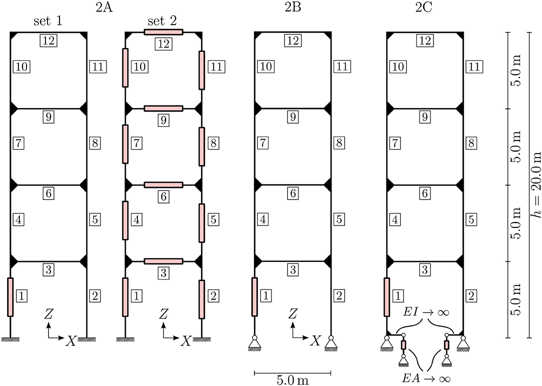
Figure 6. Example 2, frame design: investigated variants with dimensions and actuator positions.
The proof of stability for all beams is simplified on the safe side. For the computation of Euler's critical buckling load it is assumed that all beams are hinged at both ends and that the beam element with the smallest bending stiffness is decisive for the computation of the critical buckling load. The first assumption neglects the bending stiffness of the rigid joints; if all stiffnesses were correctly taken into account, the resistance of the beams against buckling would be higher. Therefore, the assumptions are on the safe side in this case. Regardless of these assumptions, the computations show that member buckling is not critical for design in the investigated cases. As mentioned before, no distributed loads are applied, so linearly varying bending moments are expected in the structure. To approximate a linearly varying cross-section along one beam, the beam is discretized using 10 beam finite elements of constant cross-section. Further improvements could be achieved by the introduction of e.g., linearly varying cross-sections or a finer discretization of the beam. In the following, the terms beam element and element specify a single finite element, and a beam connecting two loaded or supported nodes consists of 10 beam elements. Figure 6 shows the positions of the actuators in varying beams of the frame structures. Since it suffices for only one element of a beam to be an active element, the exact position of the active element within one beam is not shown.
For frame structures, which are very typical for e.g., multi-story buildings, the degree of static indeterminacy is typically greater than for simple truss structures. The number of actuators needed to control all internal forces arising from constraints is significantly higher than for trusses. The assumption that only linear actuators in the central axis of an element are available is not suitable for frame structures, because, in contrast to truss structures, the degree of static indeterminacy in frame structures can be greater than the number of elements. This leads to the hypothesis H3 for beam structures: “Actuation using only axial linear actuators is not sufficient to enable a well-performing adaptive frame structure. Direct manipulation of bending moments and transverse shear forces is necessary.”
In order to check this hypothesis, several variants of the structure are introduced. For the basic configuration, 2A, two actuator sets are compared. Set 1 has only one actuator, which can manipulate the displacements but will introduce additional internal forces due to internal constraints in the structure. Set 2 has a total of 12 actuators, one in each beam, to test whether it is possible to control the internal constraint completely. The setup of variant 2B is inspired by insights into load-bearing behavior from a structural mechanics point of view. The actuation of the structure can be constraint-free when using hinged supports, as shown in the middle diagram of Figure 6. The axial forces in both columns are statically determinate now, so there is no additional force arising from actuating one of these elements.
The resulting cross-sections from the optimization processes are shown in Figure 7 (2A and 2B). Because of the missing clamping at the supports, and hence the missing stiffness for preventing large deformations, the variant 2B performs worse in terms of the amount of material used, although the adaptation is constraint-free. As shown in Table 2, instead of 8,193 kg a total mass of 14,059 kg is needed to provide a functional passive building, and instead of 1,978 or 1,935 kg a new mass of 2,532 kg is needed for the adaptive structure. Relative to the passive structures, the mass-saving potentials of the adaptive structures are between 76 and 82%. This significant mass-saving potential can be traced back to the very inefficient load-bearing behavior of the passive construction. Horizontal deformation depends on the bending stiffness, which leads to an extensive need for material. Interestingly, the full actuation of the structure using set 2 does not yield significantly greater material savings.
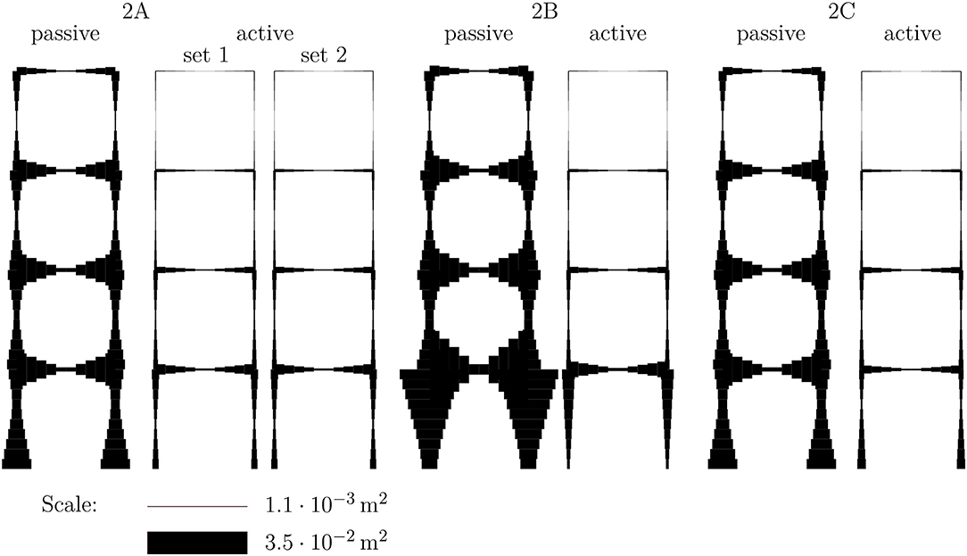
Figure 7. Example 2, frame design: optimized cross-sectional areas.
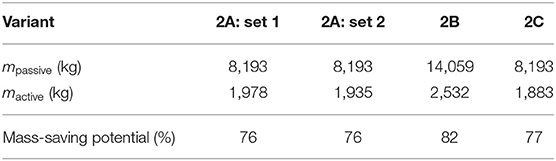
Table 2. Example 2, frame design: total masses and mass-saving potentials (additional actuator mass not considered).
To overcome this issue, adaptive clamping of the support is investigated. This can be represented in the model by starting with variant 2 and introducing two additional actuators at the bottom of elements 1 and 2; see the right diagram of Figure 6. These actuators can enable a constraint-free rotation of the beam at the support if they are controlled to introduce no actuation force. On the other hand, these actuators prevent (additional) rotation at the support if they are controlled to hold their actual stroke level. Therefore, variant 2C is an intermediate version between variants 2A and 2B. To preserve comparability of the results, the cross-section of these additional elements is taken to be very large compared to all the other elements and is assumed to be completely rigid. The mass of the additional elements is not considered, because the switchable clamping is part of the supporting structure, whose weight is also not considered in the other examples. Generally speaking, a clamping needs more mass than a hinged support.
The resulting structure after optimization of variant 2C is shown in the right diagram of Figure 7. The switchability of the clamping in the support offers the possibility of constraint-free manipulation of the displacements with the actuator in element 1, combined with the additional stiffness of the clamping. Therefore, this results in the adaptive structure having a total mass of 1, 883 kg, which is 26% less than variant 2B and even 3% less than variant 2A. Even for a structure that is packed with active elements, such as variant 2A with actuator set 2, optimal performance in terms of mass-saving cannot be achieved. Actuators for direct manipulation of the bending moments or transverse shear forces have to be introduced. The workaround we have introduced provides an easy way to model an actuator that can apply a bending moment at the support. It can be concluded that hypothesis H3 holds in this case.
4. Conclusions and Further Work
New challenges arise in the design of adaptive structures compared to the design of passive structures. For classical passive structures, it is well-known how to lay out a structure so that it is efficient, reliable, redundant, cheap, etc. With adaptive elements coming into play, using intuition gained from the design of passive structures may lead to suboptimal results, because such intuition does not fully take into account the particular characteristics of adaptive structures. The two academic examples investigated in this study demonstrate the changes in the requirements, which are not necessarily obvious. The results represent an important step toward developing the needed design guidelines, although the process is still far from complete. The results presented in this paper can help to advance research into the optimal number and placement of actuators, while maintaining the reliability of the whole adaptive structure and, of course, controlling its cost. The results also highlight some opportunities that are opened up by the introduction of adaptive civil structures. Significant mass savings can be achieved, and serviceability can also be improved.
The results of this study provide new insights into the nascent field of designing adaptive structures. The first example investigates the incorporation of actuators into passive truss structures, and the second example examines a similar procedure for frame structures. For both of the investigated structures, significant mass-saving potentials of more than 65% in the primary structure can be achieved by using actuators, compared to the passive version of the structure, under the given assumptions. The potential savings are greater for the frame structure than for the truss structure. These results apply to the utilization of adaptive structures in stiffness-governed design tasks. The examples look at only several different variants and do not yet provide a genuine process for designing an adaptive structure. More investigations have to be carried out in order to formulate a suitable design process. The aim would not be to design passive structures and make them adaptive afterwards, but rather to design adaptive structures in an integrative design process; this would be an important continuation of the present study to a more applicable setting.
For future work, the investigation of different actuation concepts for frame structures would be the most important extension of the present study. Therefore, non-linear actuation and elements for bending and shear actuation also need to be taken into account. The inclusion of non-linear effects for beam actuators represents the next challenge in the optimization of adaptive structures, because optimized adaptive structures are getting more and more slender and hence non-linearities have to be considered in the simulation process. Additionally, it is planned to extend these investigations to plates and shells.
Data Availability Statement
All datasets generated for this study are included in the article/supplementary material.
Author Contributions
This research was initiated and globally supervised by MB. FG and JG developed the modeling, design strategies, and formulation, as well as executed the optimization processes together. FG contributed the selection and evaluation of the case study. The modeling and the case study were supervised by MB. MS supervised the optimization part. The first draft of the paper was written by FG. All authors actively revised, reviewed, and approved the final submission.
Funding
The work described in this paper was conducted in the framework of the Collaborative Research Center 1244 Adaptive Skins and Structures for the Built Environment of Tomorrow, within the projects A04 Form finding, structural optimization, and system optimization and B01 Characterization, modeling, and model order reduction, funded by the Deutsche Forschungsgemeinschaft (DFG, German Research Foundation) under project number 279064222. The authors were grateful for the generous support.
Conflict of Interest
The authors declare that the research was conducted in the absence of any commercial or financial relationships that could be construed as a potential conflict of interest.
References
Frecker, M. I. (2003). Recent advances in optimization of smart structures and actuators. J. Intell. Mater. Syst. Struct. 14, 207–216. doi: 10.1177/1045389X03031062
Fröhlich, B., Gade, J., Geiger, F., Bischoff, M., and Eberhard, P. (2019). Geometric element parameterization and parametric model order reduction in finite element based shape optimization. Comput. Mech. 63, 853–868. doi: 10.1007/s00466-018-1626-1
Furuhashi, R., and Mura, T. (1979). On the equivalent inclusion method and impotent eigenstrains. J. Elast. 9, 263–270. doi: 10.1007/BF00041098
Geiger, F., Gade, J., von Scheven, M., and Bischoff, M. (2020a). “Anwendung der Redundanzmatrix bei der Bewertung adaptiver Strukturen [Application of the redundancy matrix in the assessment of adaptive stuctures],” in Baustatik-Baupraxis, eds B. Oesterle, M. von Scheven, and M. Bischoff, Vol. 14 (Stuttgart: Institute for Structural Mechanics, University of Stuttgart), 119–128.
Geiger, F., Gade, J., von Scheven, M., and Bischoff, M. (2020b). Optimal Design of Adaptive Structures vs. Optimal Adaption of Structural Design. Berlin: IFAC-PapersOnLine.
Hale, A. L., Lisowski, R. J., and Dahl, W. E. (1985). Optimal simultaneous structural and control design of maneuvering flexible spacecraft. J. Guid. Control Dyn. 8, 86–93. doi: 10.2514/3.19939
Kawaguchi, K.-I., Hangai, Y., Pellegrino, S., and Furuya, H. (1996). Shape and stress control analysis of prestressed truss structures. J. Reinf. Plast. Compos. 15, 1226–1236. doi: 10.1177/073168449601501204
Kirsch, U. (1991). Optimal design of structural control systems. Eng. Optim. 17, 141–155. doi: 10.1080/03052159108941066
Kirsch, U., and Moses, F. (1977). Optimization of structures with control forces and displacements. Eng. Optim. 3, 37–44. doi: 10.1080/03052157708902375
Korkmaz, S. (2011). A review of active structural control: challenges for engineering informatics. Comput. Struct. 89, 2113–2132. doi: 10.1016/j.compstruc.2011.07.010
Kwan, A., and Pellegrino, S. (1993). Prestressing a space structure. AIAA J. 31, 1961–1963. doi: 10.2514/3.11876
Martins, J. R. R. A., Sturdza, P., and Alonso, J. J. (2003). The complex-step derivative approximation. ACM Trans. Math. Softw. 29, 245–262. doi: 10.1145/838250.838251
Melosh, R. J. (1963). Basis for derivation of matrices for the direct stiffness method. AIAA J. 1, 1631–1637. doi: 10.2514/3.1869
Pellegrino, S., and Calladine, C. (1986). Matrix analysis of statically and kinematically indeterminate frameworks. Int. J. Solids Struct. 22, 409–428. doi: 10.1016/0020-7683(86)90014-4
Senatore, G., Duffour, P., and Winslow, P. (2018). Energy and cost assessment of adaptive structures: case studies. J. Struct. Eng. 144:04018107. doi: 10.1061/(ASCE)ST.1943-541X.0002075
Senatore, G., Duffour, P., and Winslow, P. (2019). Synthesis of minimum energy adaptive structures. Struct. Multidiscipl. Optim. 60, 849–877. doi: 10.1007/s00158-019-02224-8
Senatore, G., Duffour, P., Winslow, P., and Wise, C. (2017). Shape control and whole-life energy assessment of an ‘infinitely stiff’ prototype adaptive structure. Smart Mater. Struct. 27:015022. doi: 10.1088/1361-665X/aa8cb8
Soong, T. (1988). State-of-the-art review: active structural control in civil engineering. Eng. Struct. 10, 74–84. doi: 10.1016/0141-0296(88)90033-8
Soong, T. T., and Manolis, G. D. (1987). Active structures. J. Struct. Eng. 113, 2290–2302. doi: 10.1061/(ASCE)0733-9445(1987)113:11(2290)
Soong, T. T., and Spencer, B. F. (1992). Active structural control theory and practice. J. Eng. Mech. 118, 1282–1285. doi: 10.1061/(ASCE)0733-9399(1992)118:6(1282)
Squire, W., and Trapp, G. (1998). Using complex variables to estimate derivatives of real functions. SIAM Rev. 40, 110–112. doi: 10.1137/S003614459631241X
Teuffel, P. (2004). Entwerfen Adaptiver Strukturen (Ph.D. thesis). Stuttgart: Universität Stuttgart.
Utku, Ş. (1998). Theory of Adaptive Structures: Incorporating Intelligence Into Engineered Products. New Directions in Civil Engineering. Boca Raton, FL: CRC Press.
Wagner, J. L., Gade, J., Heidingsfeld, M., Geiger, F., von Scheven, M., Böhm, M., et al. (2018). On steady-state disturbance compensability for actuator placement in adaptive structures. At Automatisierungstech. 66, 591–603. doi: 10.1515/auto-2017-0099
Keywords: adaptive structures, structural optimization, integrative design approach, actuator modeling, adaptive truss, adaptive frame
Citation: Geiger F, Gade J, von Scheven M and Bischoff M (2020) A Case Study on Design and Optimization of Adaptive Civil Structures. Front. Built Environ. 6:94. doi: 10.3389/fbuil.2020.00094
Received: 01 April 2020; Accepted: 26 May 2020;
Published: 30 July 2020.
Edited by:
Gennaro Senatore, École Polytechnique Fédérale de Lausanne, SwitzerlandCopyright © 2020 Geiger, Gade, von Scheven and Bischoff. This is an open-access article distributed under the terms of the Creative Commons Attribution License (CC BY). The use, distribution or reproduction in other forums is permitted, provided the original author(s) and the copyright owner(s) are credited and that the original publication in this journal is cited, in accordance with accepted academic practice. No use, distribution or reproduction is permitted which does not comply with these terms.
*Correspondence: Florian Geiger, Z2VpZ2VyQGliYi51bmktc3R1dHRnYXJ0LmRl