 Raphael Neuhaus1*
 Nima Zahiri2
 Jan Petrs2
 Yasaman Tahouni3Jörg Siegert1Ivica Kolaric1Hanaa Dahy2Thomas Bauernhansl1
- 1Functional Materials, Institute of Industrial Manufacturing and Management (IFF), University of Stuttgart, Stuttgart, Germany
- 2Institute of Building Structures and Structural Design (itke), Biobased Materials and Materials Cycles in Architecture (BioMat), University of Stuttgart, Stuttgart, Germany
- 3Institute for Computational Design and Construction (ICD), University of Stuttgart, Stuttgart, Germany
Building envelopes separate the confined interior world engineered for human comfort and indoor activity from the exterior world with its uncontainable climatic forces and man-made immission. In the future, active, sustainable and lightweight building skins are needed to serve as an adaptive interface to govern the building-physical interactions between these two worlds. This article provides conceptual and experimental results regarding the integration of ionic electroactive polymer sensors and actuators into fabric membranes. The ultimate goal is to use this technology for adaptive membrane building skins. These devices have attracted high interest from industry and academia due to their small actuation voltages, relatively large actuation and sensing responses and their flexible and soft mechanical characteristics. However, their complex manufacturing process, sophisticated material compositions and their environmental sensitivity have limited the application range until now. The article describes the potentials and limitations of employing such devices for two different adaptive building functionalities: first, as a means of ventilation control and humidity regulation by embedding small actuated apertures into a fabric membrane, and second, as flexible, energy- and cost-efficient distributed sensors for external load monitoring of such structures. The article focusses on designing, building and testing two experimental membrane demonstrators with integrated polymer actuators and sensors. It addresses the challenges encountered and draws conclusions for potential future optimization at the device and system level.
Introduction
Many scientists, governments and international institutions predict a global population growth of up to 2.2 billion people between 2017 and 2050 (United Nations, 2017). Regarding this demographic increase, it is self-evident that additional buildings, roads, bridges, tunnels, and other infrastructure facilities have to be built to provide future generations with the same or higher housing standards and societal living conditions prevalent today (Tauber et al., 2019).
The construction of new buildings and infrastructure and particularly the modernization of the already existing building stock entail a growing demand for construction materials and energy resources. Even today, the construction industry is responsible for ~60% of global resource consumption, 50% of mass waste occurrence and 35% of both energy consumption and global emissions (Abergel et al., 2017).
Considering those numbers, it is necessary to find answers to the most urgent ecological and societal question of our time for the construction industry: How can we create – in view of a growing world population and shrinking resources – more sustainable housing with less material and energy consumption in the future? Employing lightweight structural systems and integrating adaptive elements into enveloping systems is considered an important approach (Klein and Knaack, 2015; Sobek, 2015; Košir, 2016).
Building envelopes, besides being exposed to climatic impacts like rain, wind and wide temperature ranges, are regulating thermal insulation, light transmission, humidity transport and ventilation. Thus, they are significantly involved in controlling the thermal and energy balance of the building. Nevertheless, their distinct features and operation principles are usually based on either high material usage (thermal energy storage, noise protection) or high energy usage (heating, cooling, ventilation, illumination). As a direct consequence, building envelopes not only contribute to the total energy and material resource consumption of the building, but their building-physical qualities strongly determine the physical and mental well-being of the users and residents. New ideas in designing lightweight and energy-efficient building envelopes go way beyond today's passive membrane structures, with some approaches currently exploring active concepts that include adaptive building-physical functionalities that can promote comfortable indoor settings (Aelenei et al., 2016; Attia et al., 2018).
One approach is being presented in this research paper, namely employing bio-inspired smart materials for adaptive ultra-lightweight building skins. The overarching objective is to present experimental methods and results regarding the integration of carbon nanotube based electroactive polymers that can be used as soft and flexible actuators and sensors in fabric membrane structures.
State of The Art
Structural Membranes as Building Envelopes
Since the second half of the 20th century lightweight building skins such as multi-layer fabric or foil-based membrane structures have been in the focus of architects and engineers and increasingly found their way into airport façade systems, roofing structures for stadiums and iconic temporary or stationary public buildings around the globe (Habermann and Koch, 2004).
New advances in polymer technology have brought new membrane materials to the market, accounting for improved life spans, optimized mechanical properties, dirt-repellent and UV-resistant characteristics and the very important features of translucency (fabrics) and transparency (foils). They usually make use of multifunctional single-layer membranes and profit from their low material thicknesses of usually below 1 mm. The resulting low weight of the membrane cover leads to a relief of the load-bearing structures and thus to a reduction of necessary construction materials (Paech, 2016).
The Need for Adaptivity
Recent works have been published on design and optimization methods to reduce material and energetic impacts of civil structures through integration of active control (Senatore et al., 2018a,b, 2019). The building-physical properties and other distinct features of membrane skins, however, are usually static and non-changeable. They are designed and installed for specific use cases to operate within certain climatic conditions which are strongly related to the building's geographic location. Often no adaptive functionality is required, because energy-intensive artificial climate control still dominates the current practices in regulating comfort settings. However, in order to yield maximum energy efficiency and building performance, the building envelope needs to respond dynamically to changing environmental conditions and user comfort requirements.
Adaptivity in building skins can provide diverse functionalities: A controlled breathability may be desired to manage hygrothermal conflicts such as specific humidity and ventilation requirements or to prevent interstitial condensation in multi-layer membrane structures (Janssens, 1998; Cremers et al., 2016). The inflexible light transmission rates of construction membranes may be met with novel adaptive shading strategies involving kinetic devices or actuators directly integrated into the building skin. A geometric deformation of distributed façade elements may have many functions simultaneously, e.g., a variable sun shading function, a means of ventilation and humidity control or an induced change in local wind pressure forces by adjusting the building surface topology (Loonen et al., 2015).
Traditional actuators that were proposed for such tasks include pneumatic and electronic actuators, electro-magnetic motors and hydraulic cylinders (Janocha, 2004; Haase et al., 2011). However, the weight and size penalties, complex transmissions, high induced noise levels, restrictive shapes and the need for resource-intensive maintenance of such actuators have led researchers to investigate alternative technologies for more effective substitutes with larger mechanical flexibility and compliance, down-scalability, high power-to-weight and power-to-volume ratios and high efficiency. Finding such substituting systems is specifically necessary for the application in lightweight membrane building skins where traditional rigid actuators are difficult to integrate.
In recent years, a number of smart materials have been proposed for the integration into adaptive building envelopes, some of which could also be employed as sensors. Integrated sensors in building skins are useful to monitor external wind and snow loads, manage its energy demand and empower occupants or intelligent systems to take action.
Responsive and Smart Materials
It is desired to have soft and flexible actuators and sensors to avoid complex mechanical parts within adaptive building skin elements. A variety of smart materials have been proposed in this regard. Among the most interesting materials are thermally triggered bi-metal actuators and shape memory alloys (SMA) which both react to ambient temperature changes and have been suggested for adaptive ventilation and shading systems in architectural skins (Sung, 2011; Dewidar, 2013). Hygroscopic wooden bilayer composites have been explored to enable adaptive apertures that react to changing humidity and temperature conditions (Reichert et al., 2015). Such self-controlled materials, however, only respond to ambient environmental parameters and cannot be directly stimulated or controlled by humans.
For this reason, electroactive polymers (EAP) have attracted global interest among scientists and are believed to have a potential role in civil engineering and architectural applications (Kretzer and Rossi, 2012; Juaristi et al., 2018). These soft and flexible smart material systems exhibit a reversible change in size or shape when stimulated by an electric field. Despite their advantageous capability to combine sensor and actuator functionalities, they have not yet seen any commercial deployment in a wider architectural context.
Electroactive Polymers
There are two main groups of EAP prevailing in R&D today. The first and largest group – by numbers of publications and proposed applications – are the dielectric elastomer actuators (DEA) whose operation mode is based on purely physical effects. The second group consists of various sub-types of ionic EAP (IEAP), where actuation is based on electrochemical working principles.
DEA have a passive elastomer film with a high dielectric constant sandwiched between two compliant electrodes. Upon applying high electric voltages, the elastomer film is squeezed by the electrostatic pressure between the electrodes and therefore expands in size in planar direction. Regarding applications in built environment, they have only been proposed as an air flow actuator in HVAC systems by Berardi (2010), for daylighting control systems in homeostatic façades (Decker, 2013) and for a dynamic and responsive indoor arts installation mounted to a room ceiling in the project “Reef” by Mossé et al. (2012). Deformations of DEA are well-controlled, reversible, and capable of high-frequency operation, but they require very high driving voltages of several kilovolts for actuation. In this regard the operation of DEA as soft actuators in building envelopes may potentially be harmful for the residents and is thus not considered in this research paper.
Unlike DEA, IEAP operate on the principle of electrically controlled ion transport within a bi- or tri-layer setup and in most cases perform a bimorph bending motion. Some exhibit large deformation and medium force transmission at low operational power (<3 V), making them highly attractive for many applications where soft, non-hazardous and noise-free actuation is desired. Although several IEAP materials and their properties have been known for many decades, they have found very limited applications and have not replaced traditional actuators (electromagnetic, pneumatic, hydraulic, and piezoelectric) because of complex manufacturing techniques, costly materials or poor actuation performance (Chang et al., 2018).
Focus – Specific Target Applications
Integrating soft and flexible actuators and sensors into membrane building skins can provide a variety of adaptive functionalities (see section The Need for Adaptivity). For this article, we focus on two application scenarios:
Switchable Breathability
Especially during winter time the temperature drop between the inside and the outside of a building skin can be significant. If humidity is trapped inside a confined multi-layer membrane structure and if the vapor pressure sets below the saturation pressure, condensation may occur. Condensation is an unwanted phenomenon as it may cause dampness, mold health issues, corrosion, material fatigue, and energy penalties due to increased heat transfer (Haase et al., 2011). Contemporary multi-layer membrane structures cannot breathe like conventional masonry walls, where humidity is simply dried out over time due to capillary diffusion processes. For this reason mechanical air heaters are often used to blow hot air through the interstitial space removing humidity. In view to avoid such energy intensive systems in the future, the first application scenario is an adaptively breathable membrane lowering the risk of interstitial condensation. This can be achieved by controlling the hygrothermal balance via integrated switchable apertures enabled by soft and flexible IEAP actuators.
Wind Load Monitoring
The second application scenario addresses load and stress sensing for fabric or foil-based membrane building skins. Strong wind loads, for example, first need to be detected before potential countermeasures can be taken. It is often desired to have locally resolved data about induced mechanical stresses inside membrane structures for health monitoring purposes and to ensure the serviceability and safety of the structure (Tang et al., 2019). We propose soft and flexible IEAP sensors for direct integration into tensile membrane structures as a viable alternative to the installation of conventional acceleration sensors and displacement meters.
Selection, Manufacturing and Testing of Soft Actuators and Sensors
Types of Ionic EAP
Various types of IEAPs that can be operated under low voltage conditions have been developed, including conducting or conjugated polymers (CPs), ionic polymer–metal composites (IPMCs), carbon nanotube (CNT-) or Bucky gel polymers, and interpenetrating polymer networks (IPNs).
Conjugated polymers (CPs) represent a class of intrinsically conducting polymers such as polypyrrole, polyaniline, PEDOT:PSS and polythiophene that have unique actuation properties (Melling et al., 2019). Their working principle is based on volume change in the electrodes due to the insertion and extraction of counter ions into the polymer matrix. In contrast to other IEAP, chemical oxidation and reduction processes occur at the ion-polymer interfaces. CPs usually operate in liquid electrolyte environments and are thus often proposed for biomedical applications, where the surrounding fluids (e.g., blood) can serve as an electrolyte. There are concepts of in-air operating CP actuators using an Interpenetrating Polymer Network (IPN) that contains the liquid electrolyte (Plesse et al., 2005). Such IPNs use one polymer network as ion conducting material and a second polymer network to provide the required mechanical properties. Newer research has proposed ink-jet printing of PEDOT:PSS on IPN networks for mass production of air-operating artificial muscles and supercapacitors (Nakshatharan et al., 2018). Other findings provided fast and durable CP actuators using graphene and a percolation network of silver nanowires to enhance the conductivity of the PEDOT:PSS electrodes (Park et al., 2018). An advantageous feature of CPs is that they hold their produced strain under DC voltage and at open circuit states.
The most commonly known IEAP is the ionic polymer-metal composite (IPMC) which is predominantly used as an actuator. IPMCs are composed of an ionic polymer membrane, typically Nafion, sandwiched between a pair of noble metal electrodes (Nakshatharan et al., 2018; Tamagawa et al., 2019). When a voltage is applied to the metal electrodes of an IPMC, it causes directional motion of mobile cations together with water molecules from the ionic membrane to the electrode surfaces, where they form an electrochemical double layer. The excess of cations and water near the negatively charged electrode causes swelling which results in bending toward the positive electrode. IPMCs are, like CNT- or Bucky gel actuators, capable of self-sensing (Kruusamäe et al., 2015).
Unlike IPMCs, CNT-based IEAPs employ a pair of polymer supported Bucky gel electrodes containing CNTs instead of noble metal electrodes. Bucky gel is a highly viscous and electrically conductive gel obtained by physical cross-linking of highly entangled CNT bundles in the presence of imidazolium-based ionic liquids (IL). Such gels are stable at wide temperature ranges and do not shrink or dry out under reduced pressure due to the non-volatility of the ionic liquid. They can also be incorporated into a polymeric composite matrix to form free-standing conductive electrodes, which were used to build the first Bucky gel actuator that could operate in air without external electrolytes at comparably low applied voltages (± 3.0 V) (Fukushima et al., 2005).
The bending motion of CNT- or Bucky gel actuators is mainly caused by three superimposing effects, the first being the electrostatic attraction (or repulsion) between differently (or equally) charged neighboring CNTs within the Bucky gel electrodes (Baughman et al., 1999). The second effect is caused by dimensional changes within individual CNTs themselves due to C-C bond elongation upon charge injection (Roth and Baughman, 2002). The third effect is due to transport of oppositely charged ions of different sizes to the cathodic and anodic side of the actuator, where they form electrochemical double layers with the positively and negatively charged CNTs. Since the BMI+ cation is much larger than the anion in the ionic liquid, the ion transport leads to swelling of the cathode and shrinking of the anode side, respectively. Consequently, the actuator bends toward the anode side.
Benchmarking Performance Characteristics of IEAP
For a decision about which type of IEAP is most suitable for the desired target applications it was deemed necessary to compare their performance characteristics. To generate apertures in fabric membranes for building envelopes, long operation life-times and reproducibly strong forces and displacements are necessary. Slow actuation responses on the other hand should not have a negative impact, because changes in ambient temperature and humidity are also slow. Maximum internal material strains are key performance indicators for IEAP bending actuators. They indicate the unidirectional change of length within the electrode layers and, therefore, relate directly to the induced stress due to ionic transport forces. Induced bending strain and stress values are independent of the size or geometry of IEAP actuators, thus they can be used for direct comparison of their performance.
For benchmarking purposes, induced strain and stress values of different reported IEAP species have been collected from a variety of publications and are assembled in Figure 1. The illustrated performance boundaries take into consideration actuators operable in air only and depict values obtained under very low actuation frequencies (<0.1 Hz). Other actuator technologies such as SMA, DEA, skeletal muscles and others are also included for comparison.
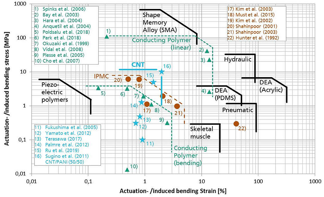
Figure 1. Stress vs. strain of typical actuator technologies (solid black lines) and some state-of-the-art ionic EAP actuators operable in air – inspired by Simaite (2015) and based on sources referenced in the diagram.
Most IEAP species exhibit similar stress/strain combinations around 1 MPa and 1%, respectively, however CNT Bucky gel actuators appear to be especially promising. Furthermore, most reported IPMC actuators exhibit substantial back-relaxation effects, which is the unwanted behavior of a DC-excited actuator to slowly relax back toward its initial shape instead of holding its bent state (Vunder et al., 2012). Research on CP actuators has made tremendous progress in counteracting delamination and improving the electromechanical coupling efficiency and their cycle stability. However, the complex manufacturing techniques required for synthesizing and doping conductive polymers such as polypyrrole or PEDOT:PSS as well as the laboratory production of typically very thin actuators resulting in relatively low blocking forces have so far hindered a greater commercial adoption of this IEAP technology. CNT actuators on the other hand have reproducibly delivered strong actuation merits in previous projects (Addinall et al., 2014) and the authors believe that their simple and up-scalable manufacturing techniques, their proven in-air operability and their sensory capabilities are important features when assessing their application potential for civil engineering structures. Without eliminating the possibility of other IEAP species also being compatible for the described application scenarios, CNT actuators were regarded as a premium choice for this project. Figure 2 shows the electrochemical processes inside the three layer system leading to deformation of CNT actuators.
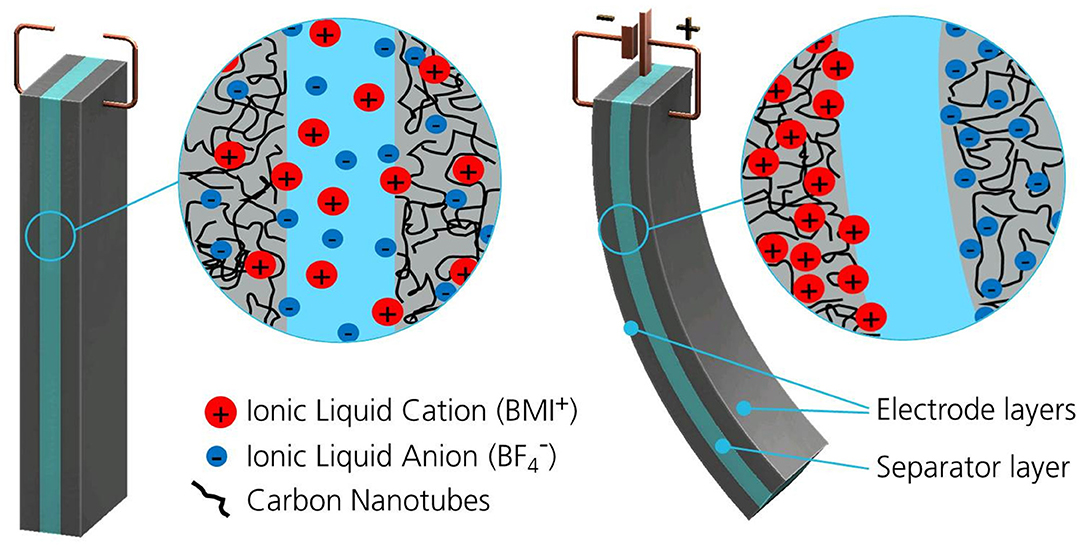
Figure 2. Illustration of CNT “Bucky gel” actuator in the non-actuated and in the actuated state. The curvature is mainly caused by charge induced transport of differently sized ions into the electrode structures.
All IEAP species are reported to have lifetime expectancies (sometimes referred to as “cycle life”) of 104-107 working cycles, depending on the test environment, the applied power settings and choice of materials. Given an estimated average actuation frequency of five cycles per day the proposed application scenarios would yield a minimum lifetime expectancy of more than 5 years.
The authors would like to emphasize that in the following sections of this article the expression “actuator” always refers to IEAP with both actuator and sensor capabilities.
Manufacturing Methods of Ionic CNT Actuators
Until recently, the manufacturing process of CNT-based EAP actuators was a lab-scale fabrication method using small batches of raw materials and involving manual dispersion, casting and handling techniques. The authors have studied industrial dispersion and manufacturing techniques that enhanced the performance reproducibility of CNT-based actuators while simultaneously increasing the manufacturing speed and decreasing material costs. The findings of Sugino et al. (2011) served as a baseline for obtaining optimized material compositions for the actuators (Figure 1). Parts of the manufacturing procedure have been published by the authors in Neuhaus et al. (2019b).
Dispersion Techniques
The first step in actuator fabrication is to make homogeneous dispersions for both actuator electrodes and separators. In order to yield large electrochemical effects in the actuator electrodes – and thus high internal material strain for actuator deflection – a thorough separation of CNT agglomerates and an even distribution of all material components in the final dispersion is essential. Through the Design of Experiments (DoE) method it was possible to replace single-walled CNTs (SWCNTs) with much cheaper multi-walled CNTs (MWCNTs) that are easier to produce and available in large commercial quantities.
The fabrication of actuator electrodes and separators starts by dissolving polyvinylideneflouride-cohexafluoropropylene [PVDF(HFP)] in the organic solvent 4-methyl-2-pentanone (4M2P). The polymer later serves as a matrix for the ionic liquid and the carbonaceous additives and is responsible for the actuator's stiffness. The room temperature ionic liquid 1-Butyl-3-methylimidazolium tetrafluoroborate (BMI-BF4) is added to both dispersions and constitutes a non-volatile electrolytic ion reservoir. The electrode dispersion receives MWCNTs as the main active material (Nanocyl® NC7000) for sufficient specific surface area and Polyaniline (PANI) for enhanced electrode conductivity. Stirring of the dispersions and subsequent high frequency treatment in an ultrasonic bath has been reported to last up to 72 h to yield sufficient homogenization (Sugino et al., 2011; Palmre et al., 2012). By applying high-power dispersion devices such as an ultrasonic sonotrode it was possible to reduce the overall dispersion time to <3 h, which is a significant improvement compared to conventional techniques.
Printing CNT Actuators
Printing of electrode and separator layers was performed with the discontinuous coating machine Easycoater EC 63 from Coatema Coating Machinery GmbH (Germany) that was specifically set up and re-designed for this project. Electrode and separator dispersions can be pumped separately into two different slot-die nozzles allowing for automated layer-by-layer printing without changing the slot-die configurations between different layers. Both slot-dies have a nozzle length of 200 mm. The width of the nozzle slot is 250 μm for the electrode slot-die and 100 μm for the separator slot-die. When the layers are applied onto the heated printing table with exactly controllable wet layer thickness, hot-air assisted drying accelerates the evaporation of the solvent. After 10 min, the layers are dry enough for the next layer to be printed. Alternatively, layers can be printed individually and later hot-pressed together for assembly of actuators and sensors.
Actuator Assembly – Separating Mechanical and Electrical Contacts
After printing the actuator layers, usually small rectangular pieces are cut out of the tri-layer compound. These actuators are not yet fitted with electric connections. For testing purposes, the bare electrode surfaces are mechanically clamped in between two conductive voltage terminals to perform their bimorph bending motion. However, future applications require reliable electric contacts for simplified system integration and to improve the contact resistance between the main conductor (e.g., a cable) and the polymer electrodes. For testing such electric contacts, different flexible conductors were integrated into the actuator electrodes during and after the printing process. Silver plated conductive threads (Madeira HC 12 & HC 40), desoldering copper braid (Soder-Wick Rosin 50-6-25), adhesive copper foils (3MTM 11816 copper tape with acrylic conductive adhesive) and conductive epoxy glue (CircuitWorld CW2400) were tested for their applicability as embedded conductors. Dimension and resistivity parameters of all investigated conductive contact materials can be found in Table 1.
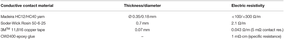
Table 1. Dimension and resistivity values of commercial conductive materials used for embedding electric contacts into IEAP actuators and sensors.
The solid conductors (yarn, desoldering braid, copper tape) were initially integrated into the wet electrode layers by placing them inside the printing mask where they were submerged by the electrode dispersion during stencil printing trials (Neuhaus et al., 2019a). After adoption of the new automated slot-die printing process, the conductors were sandwiched in between two printed and dried electrode layers of preferred shape and hot-pressed together. The resulting thick double-layer electrodes now featured firmly embedded electric contacts. The final assembly of the electrode-separator-electrode actuator composite was again done by hot pressing and produced a complete tri-layer actuator with two embedded electrode contacts for facilitated system integration (Figure 3).
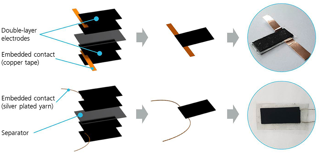
Figure 3. Concept and implementation of IEAP actuator and sensor assembly by embedding conductive contact materials into electrodes.
Automated Actuator Testing
A fully automated test setup has been implemented for CNT actuator performance measurements. Actuators are clamped into a fixture which provides electric contacts to both electrodes as depicted in Figure 4A, allowing the actuator to bend in both directions. The bending displacement is measured via optical laser triangulation (MicroEpsilon OptoNCDT 1302) with a range of 20 mm and an accuracy of ± 4 μm. Lateral bending curvatures as depicted in Figure 4B are neglected in this measurement setup. A force sensor (KYOWA LTS20GA, 500, 0.01 mN resolution) is mounted on the moving part of a horizontally adjustable servo slide (Nanotec Munich KOWI), providing position resolved blocking force measurements on one side of the actuator specimen. A potentiostat triggers the actuation by providing a predefined tunable voltage level with high accuracy, varying the electric current according to the actuator's present impedance. Other parameters obtained by the measurement setup are electric current values, motor positions, temperature variations and heat radiation images, which are not further illuminated in this article. All measurement devices are connected to a National Instruments NI PCIE-6363 DAQ card and linked with a connector block NI SCB-68A for signal-PC-interface to the motherboard. All parameters and devices are controlled by a central LabVIEW interface for direct display and automated data storage.
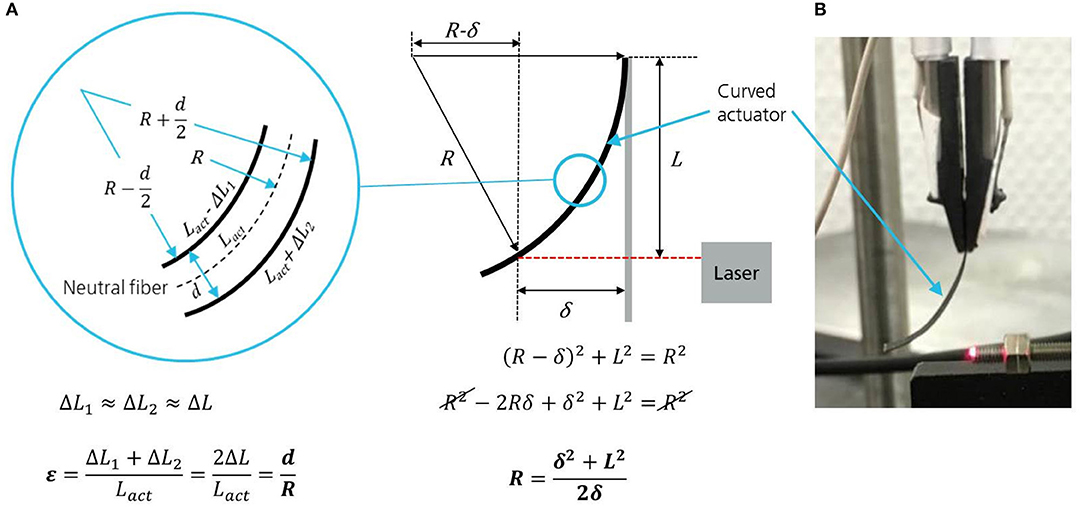
Figure 4. (A) Schematic drawing for explaining the evaluation of the strain from the displacement (B) CNT actuator clamped into the test-setup for performance characterization.
For thin actuator strips the induced strain difference ε can be directly calculated by measuring the free tip displacement δ of a clamped actuator using equation 1:
L is a fixed distance from the clamping of the actuator, marking the free length where the tip displacement δ is measured, whereas d is the thickness of the actuator strip. Figure 4A helps to understand the relationship between bending curvature and induced strain difference. R is the curvature radius and ΔL1, ΔL2 are the induced length changes in each electrode. Equation (1) holds for small deflections so that it can be assumed that the neutral fiber does not change its length after bending and deforms into an arc. Thus a uniform bending curvature has been assumed for the actuator displacement, which is fairly accurate for fully actuated bending states. By measuring the Young's modulus of the stretched or squeezed electrode layers it is possible to obtain the induced stress values of each actuator. Tested actuators that were assembled with fully printed MWCNT electrode layers showed induced bending strains of 1.4% and blocking forces of up to 30 mN at ±2.5 Vpp applied square-wave voltage and 0.05 Hz actuation frequency at room temperature. Thicker actuator electrodes lead to higher bending forces while an overall thinner actuator results in a faster speed and larger displacement.
Actuator Encapsulation
After assembly of the active layers and embedding the electric contact materials, the actuators are still in their natural form and their conductive electrode surfaces are directly exposed to air and humidity and thus capable of interacting with the surrounding environment. Encapsulation is deemed necessary for (a) providing a strong and anti-abrasive but flexible guard layer against mechanical disruption forces and (b) protecting the complex electrochemical processes inside the IEAP actuators and sensors from the influence of ambient humidity and (c) for electrical insulation and safety purposes. Various encapsulation materials like PDMS, PU, nitrocellulose, and paraffin-composites have been tested (Rinne et al., 2019). For this project it was determined to choose PVDF for encapsulation, because this material already serves as the backbone polymer for both electrode and separator layers. A good adhesion of the encapsulation layer to the actuator surface was expected. It was found that dip-coating of single actuator elements into a solution of PVDF in 4M2P (0.5 wt%) resulted in a thin layer (10–25 μm) of PVDF deposited around the actuator. Tests showed that such encapsulation yields a moderate dielectric behavior for electrical insulation and slows down the penetration of water vapor into the active layers of the actuator (Punning et al., 2014). However, the free-tip bending displacement of coated actuators decreases considerably with each additional encapsulation layer applied (Figure 5). This is because the bending resistance grows with an increase in non-active material thickness.
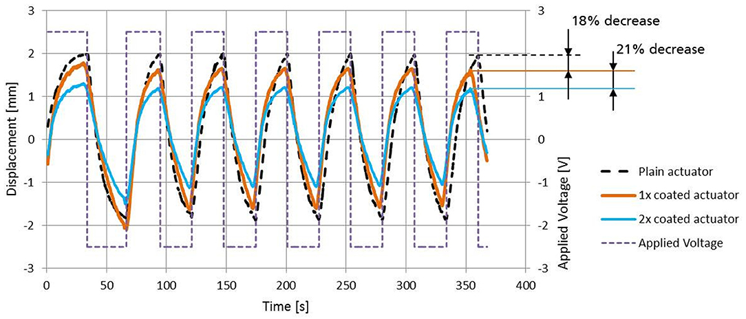
Figure 5. Impact of thin dip-coated PVDF encapsulation layers on actuator displacement. Actuator size: 20 × 8 × 0.2 mm.
Design, Manufacturing and Testing of Active Building Skin Demonstrators
Evaluation of Aperture Actuation Kinematics
There are many possibilities to create controllable apertures in tensioned membrane surfaces using soft bimorph bending actuators. Depending on their shape, their mechanical attachment to the membrane and their power capabilities, different deformation characteristics can be achieved. It was generally assumed that the passage of air should be permitted in the actuated state (open) and blocked in the non-actuated state (closed). The process of opening will be performed by applying a voltage of certain polarity to the actuator while the process of closing will be accomplished (or assisted) by switching to the opposite polarity. Apertures can be created by widening slots that were originally closed, lifting flaps that were flush with the surrounding surface or by bending of formerly plain strips covering a hole in the membrane surface. Figure 6A shows a variety of potential motion principles that could be accomplished with IEAP bending actuators. The depicted shape-changing surface elements can either consist of thin IEAP actuators themselves or they are a passive flexible material (possibly the same material as the membrane) and their deformation is induced by buckling, bending or twisting motions of IEAPs attached underneath. Some of the geometric patterns could also be used for sensing differences in air pressure produced by wind loads onto the membrane.
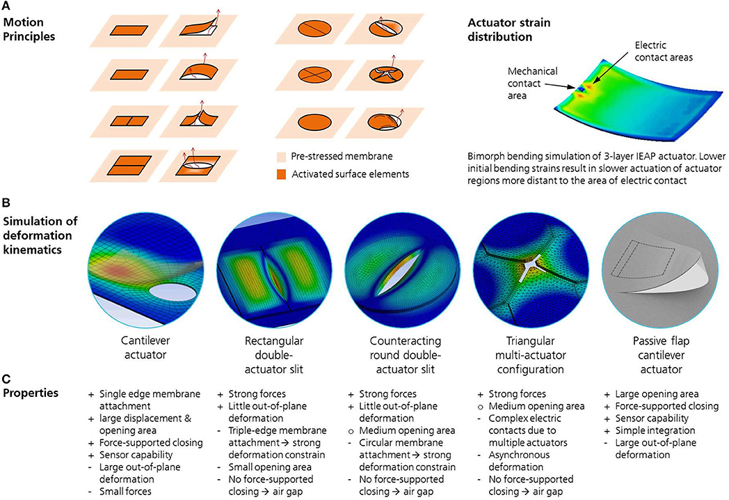
Figure 6. (A) Motion principles and (B) kinematic simulations for thin and flexible soft actuators generating controllable apertures in pre-stressed membrane structures. (C) Properties of actuating aperture concepts.
The finite element method (FEM) has been chosen to yield viable information about the deformation kinematics of IEAP actuators of different configurations attached to tensioned membranes (Figure 6B). Using ANSYS Workbench, the actuation is virtually initiated by a thermal load assigned to the electric contacts of the actuator. It causes the actuator electrodes to expand and to shrink, respectively, due to different thermal expansion coefficients assigned to the two electrodes (Addinall et al., 2014). By matching the thermal conductivity parameters of the electrode material with measured deformation data from rectangular bending actuators, a realistic simulation model could be implemented that is able to predict the motion kinematics of any actuator shape. A transient thermal simulation was performed that takes into consideration the transmission-line effect, which attributes for the slower actuation of actuator regions more distant to the area of electric contact. The main simulation target was to find suitable arrangements, sizes and shapes of IEAP actuators that produce the largest ratio of projected opening area per membrane area occupied by the actuator arrangement. The actual number of adaptive apertures needed per total membrane area depends on the climatic conditions of the target building and other construction settings such as the façade orientation, the volume of the interstitial membrane space and desired thermal insulation properties.
As a result of the analysis several actuator shapes and deformation kinematics materialized as viable configurations for the proposed application scenarios. The most efficient aperture configuration yielding the largest projected opening area was found to be the forced out-of-plane deflection of passive flaps being bent by soft actuators attached to their lower surface (passive flap cantilever actuator, Figure 6). The aperture configuration with the least out-of-plane motion and yet considerable opening characteristics was found to be a slit expansion generated by two counteracting actuators positioned underneath the edges of the slit. Initial plans to utilize the actuators themselves as opening flaps or slit generators were discarded in regards to the much larger actuator sizes required, rendering their higher material costs and energy demand as inefficient.
Demonstrator Design
Two demonstrators were designed to investigate the actuation and sensing behavior of IEAPs integrated into a fabric membrane skin. The first demonstrator comprises a double-curved multilayer membrane with controllable apertures in the inner layer. These apertures allow for a controlled ventilation of the interstitial space between the two layers and thus prevent the necessity of mechanical air blowers currently employed to avoid condensation. This setup represents a new approach to accomplish a switchable breathability in building skins. The reason for the targeted double curvature was to demonstrate the potential of soft IEAP actuators being employed despite complex membrane shapes and in the presence of multilateral tensile forces. A rhomboid shaped fabric with four equally dished edges was chosen because it permits the creation of a double curvature by pulling apart the two pairs of opposite corners, each with divergent vertical components. In this pre-stressed double-curved state, all apertures in the fabric must remain closed if not actuated. One solution is to orientate linear slit cuts (as presented in Figure 6) in the direction of the main flux of forces within the fabric so that lateral forces are minimized and the edges of each slit are not pulled apart (Figure 7). The stress distribution was analyzed using parameterized geometric models compiled in Karamba3D and running optimization algorithms regarding the positioning and orientation of the slit cuts. Karamba3D is a parametric structural engineering tool (Preisinger, 2019) that can run optimization loops on mechanical problems by changing structural parameters such as material thicknesses, cross sections, numbers of load bearing elements and spacing and positioning of these elements within given boundary conditions for internal stresses, strains and structural dimensions. It also proposes auxiliary construction measures if the solution space within a constrained approximation loop is empty. The objective of the optimization for this project was to fill the available fabric area with fifty apertures per square meter that preferably are evenly spaced, translating to twenty properly oriented slit cuts that had to be distributed evenly on the fabric's surface of ~0.45 square meters. Additionally, the routing design of the conductive pathways powering the apertures should have minimal length and run either parallel or perpendicular to the local main flux of forces to minimize cable distortion and seam failure when the membrane is stretched into a 3D shape. Another aim of an optimized routing pattern was to have two spatially separated connection areas on the demonstrator membrane, each one collecting all conductive pathways of the same polarity. This arrangement prevents the complex routing patterns that would emerge if each actuator's electric connections had individually separated access points. Furthermore, separated connection areas make it easier to attach electronic control units to power the individual actuators (or to monitor the sensor signals, respectively). Some actuators are connected individually and others are combined to actuator clusters with a single pair of electric connections. A change in routing patterns can easily be implemented due to digital design methods that allow a straightforward transfer to automated fabrication techniques. The conceptual design approach of actuator integration and distribution is depicted in Figure 8 for both demonstrators. The opening of the slit cut will be triggered by one actuator positioned on each side of a slit cut, one bending upwards and one downwards. Due to their flexibility the actuators will adapt to the local curvature of the membrane fabric without losing their motoric functionality.
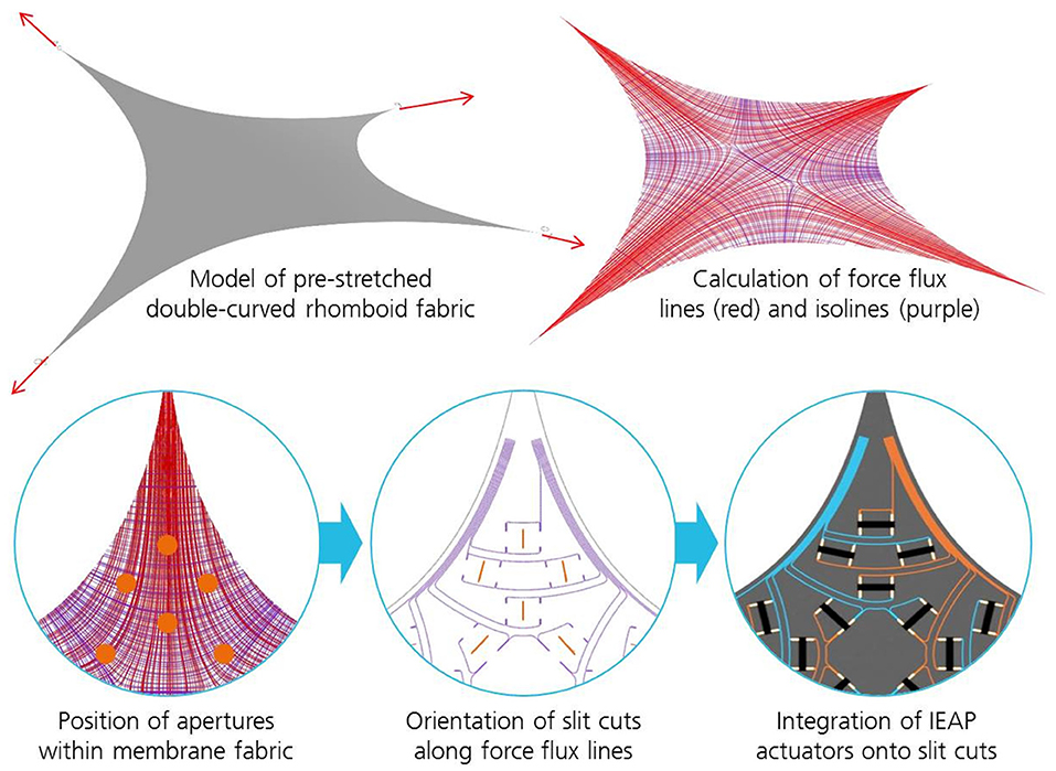
Figure 7. Methodical approach toward optimized positioning and orientation of actuated slit cuts and integration of stretch-resistant conductive pathways.
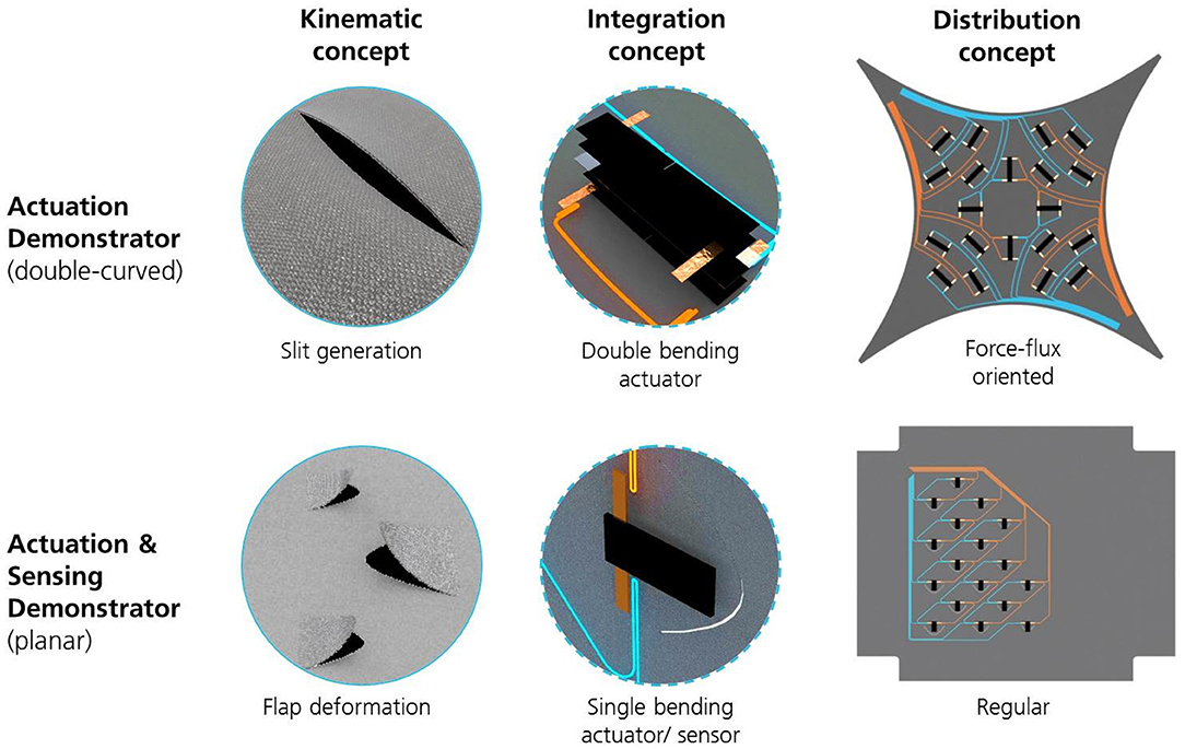
Figure 8. Concepts for IEAP integration and distribution for an actuation-only demonstrator and an actuation & sensing demonstrator. The orange and blue lines indicate the placement of the electric power distribution.
The second demonstrator will show both actuator and sensor functionalities in a single planar membrane. Parabola-shaped passive flaps are intended to deflect outwards when the IEAP actuator mounted underneath creates a bending movement. Under wind loads, the flaps should deflect inwards and provide an electrical signal that can be processed by an electronic monitoring and control unit. 17 flap cuts with three different sizes are distributed in a regular pattern on the fabric surface, without any need for algorithm-assisted optimization.
Demonstrator Manufacturing
This subsection describes the materials, techniques and manufacturing procedures that were used to build the physical demonstrators taking into consideration the findings in simulation-assisted design of aperture kinematics and electric routing patterns described above.
Preparation of Textile Membrane Fabric
For the demonstrator membrane material a gray-colored high-strength polymeric fabric made of 47% polyester, 39% polyurethane, and 14% polyamide was purchased from Tolko Stoffe GmbH in Germany. The fabric contains two thin layers of a waterproof Gore-Tex membrane (expanded Polytetrafluoroethylene - ePTFE) and is fitted with interwoven ripstop reinforcement threads in a crosshatch pattern making it highly resistant to tearing and ripping. This fabric was used for both demonstrators. By employing the same automated methods for the two fabric membranes, they were fitted with electric conductors for power distribution and received their individual patterns of aperture cuts. The conductive pathways were formed by the same conductive threads previously tested for the integrated IEAP contacts (Madeira HC 12 silver plated conductive thread). Following the pre-designed electric routing pattern, the threads were attached onto the fabric using a fully automated Tailored Fiber Placement (TFP) machine (Tajima 4-head embroidery machine). In this process the thicker conductor thread is uncoiled from the reel and placed onto the fabric by a cantilever which is attached to the machine's moving stitching head. Simultaneously, a thin auxiliary thread is alternatingly stitched over the conductor thread locking it firmly into place onto the fabric underneath. This stitching process proved to be a simple and effective method to generate arbitrary yet precise conductive pathways on any fabric surface.
The aperture cuts were made with a fully automated digital 2-axis multi-ply cutting machine (Assyst Bullmer Premiumcut ST). Via software interface it was possible to automatically assign the cutting patterns that were developed during the design stage to the machine's itinerary and transfer them onto the membrane fabric. Figure 9 illustrates the automated manufacturing steps for the first demonstrator and depicts the resulting membrane fabric equipped with conductive pathways, actuator attachment points and integrated slit cuts.
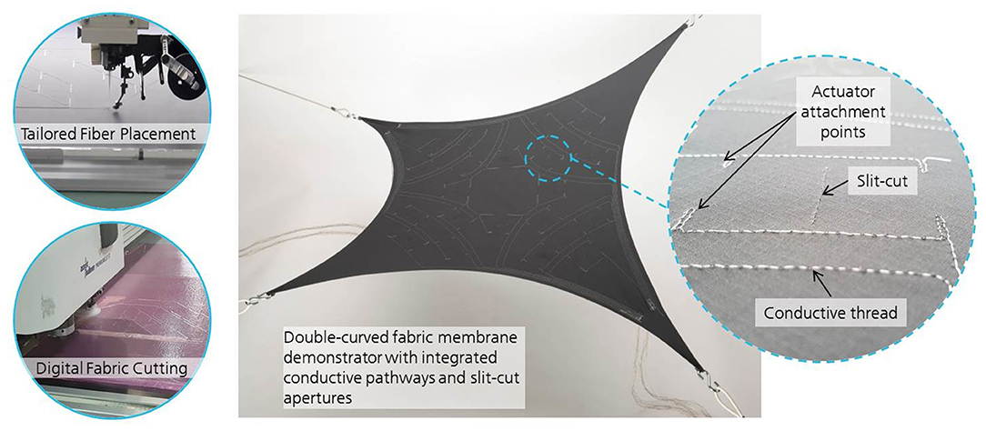
Figure 9. Membrane fabric preperation: Fully automized manufacturing processes for conductor thread integration (Tailored Fiber Placement) and patterned cutting of pre-designed apertures (Digital Fabric Cutting System).
Actuator Integration
Before turning to the actual demonstrators for IEAP integration, lab-scale tests with individual actuator geometries, aperture designs and electrical connection alternatives were performed (Figure 10). Initially, the focus was on integrating rectangular non-encapsulated CNT actuators with no external electric contacts by means of conductive epoxy glue applied to the electrode surfaces. The solvent-based glue, despite its low contact resistance, diffused into the fabric and beyond the intended attachment area during pressure-assisted curing and in many cases caused a short circuit between the two actuator electrodes. Tests with encapsulated and thread-contacted specimen showed no short circuit, but their electrical connection to the conductive pathways is only feasible by manually knotting the threads together. The most simple and robust integration method found was to apply the copper adhesive contact tapes to the provided conductor threads stitched into the fabric. The positive connection between the fabric and the actuator surface was ensured by a thin layer of double-sided adhesive tape. 40 equally shaped CNT actuators for 20 distributed apertures were integrated into the rhomboid-shaped membrane fabric of the first demonstrator and 17 actuators having the same size completed the second demonstrator with its 17 parabola-shaped flaps of three different sizes. Both demonstrators – equipped with integrated IEAP actuators – are depicted in Figure 11.
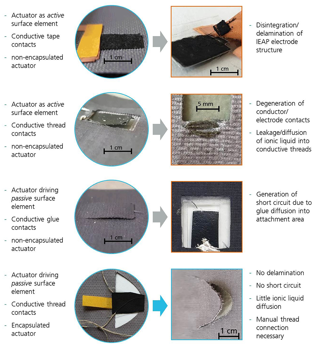
Figure 10. Evolution of IEAP actuator/sensor integration challenges.
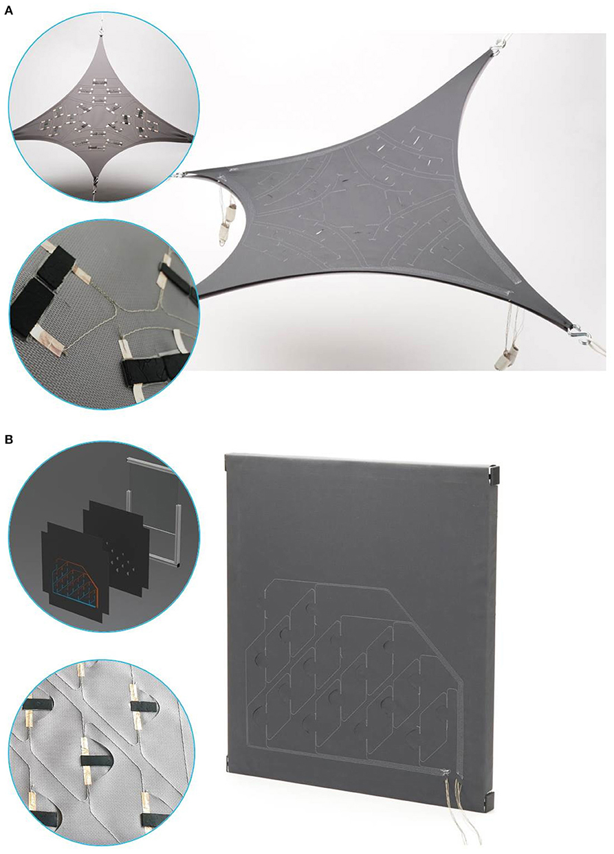
Figure 11. Final demonstrators: (A) double-curved 2-layer membrane element with controllable apertures actuated by CNT actuators. (B) Planar membrane demonstrator with controllable flaps having both actuator and sensor functionalities through integrated CNT actuators.
Experimental Testing
The displacement and blocking force of all actuators were measured using the LabVIEW-controlled automated test setup before they were integrated into the demonstrators. All actuators produced for both demonstrators had a default length of 2.5 cm, a width of 1 cm and a thickness of 300–400 μm. Both bending displacements and blocking forces were measured at 10 mm distance from the clamping (electric contact area). The measured displacement values were converted into induced bending strain values following Equation (1). Out of more than 100 actuator specimens made, only those that yielded reproducible bending strains between 0.8 and 1.2% and blocking forces between 10.5 and 21.5 mN were selected. These results were obtained with an applied square wave voltage of 2.5 V and 0.05 Hz actuation frequency. Due to encapsulation, these performance values were slightly lower compared to those of non-encapsulated printed actuators (1.4% and up to 32 mN, respectively).
For measuring the actuation performance of the integrated actuators, the pairs of conductor threads leading to the distributed apertures were connected one by one to an adjustable power source. Due to the varying length of the conductor threads and the high contact resistances at the actuator interfaces it was necessary to adjust the applied voltage levels to much higher values for the actuators to react. For the double-curved demonstrator, the maximum opening distances of the slit-cuts were measured at the actuation peak. For the flap demonstrator, the maximum tip deflection was measured.
On behalf of testing the sensing capabilities of the IEAPs integrated into the second demonstrator, the loose ends of all conductor threads leading to the distributed flaps were connected to the channels of a high-precision galvanostat/potentiostat analysis device (Ivium Octostat 5000) with low current and low voltage measurement capability. The voltage range set to 10 mV and 500 Hz sampling rate, it is possible to detect and measure very low potential differences as low as 0.01 mV with a sufficient time resolution required to resolve high-frequency phenomena during sensitivity testing. Two different test scenarios were performed.
In a first scenario, the flaps were subjected to a smooth and controlled alternating displacement in both inward and outward direction, simulating an external wind pressure. It is clear that this experimental approach does not accurately reproduce actual deformations induced by environmental forces, but this procedure was imposed to generally investigate the nature of the feedback response. The displacement and output signal were simultaneously measured. According to Kamamichi et al. (2007) a small voltage should be measured as an output signal which is expected to have almost proportional values to the displacement of the IEAP sensor. In a second scenario, a sudden forced displacement of rectangular pattern was applied to the tip of a sensing flap resting in neutral position (flush with the membrane surface). This pulsed stimulus was repeated irregularly over a 50 s period and varying holding durations. The voltage response signals of both scenarios are depicted in Figure 13.
Power Consumption and Life Cycle Assessment (LCA) of Membrane Elements With Integrated CNT Actuators
The environmental impact of an adaptive IEAP-enhanced building skin element has been analyzed by a “cradle to grave” LCA approach, taking into account all energy and materials needed during production, operation and end-of-life treatment. For all three stages the cumulative energy demand (CED) and the carbon dioxide equivalent (CDE) were calculated with the aid of an LCA software tool called GaBi-ts 2019 from sphera™. The CDE describes the global warming potential (GWP) of the energy and materials released during the system's life cycle and thus better reflects the long-term effects of the proposed system. The calculation of CED and CDE was based on the German electricity mix in 2016 and is thus in accordance with reference scenarios recommended by the European Union.
The CED to produce such a system involves the whole inventory of materials and energy necessary for synthesis, dispersion and printing processes required to build the proposed components and structures. The amount of raw materials was calculated for a scenario with fifty actuators built into one square meter of fabric membrane, one actuator consisting of two electrodes and one electrolyte layer (separator), having total dimensions of 2.5 x 1.0 cm x 380 μm. For making one electrode, one needs 1.9 mg of NC7000™ MWCNTs, 8.6 mg of polyaniline, 13.7 mg of PVDF (HFP) backbone polymer, 20.8 mg ionic liquid BMI-BF4, 1.075 g of 4M2P organic solvent, 0.2 g copper adhesive tape, 0.1 g silver coated conductive thread and negligible amounts of dispersing agents. For making one separator, 18 mg of PVDF (HFP), 18 mg of BMI-BF4 and 220 mg of 4M2P solvent are needed. Assumptions were made for the silver content of the conductive threads (10%), the exact material thickness of the fabric membrane's top layer (50 μm) and the energy demand for the catalytic carbon vapor deposition (CCVD) process for synthesizing MWCNTs, which was interpolated from bibliographical references. All catalytic materials needed for the CCVD process such as cobalt, manganese and magnesium, however, were accurately taken into account. Furthermore it was assumed that the full amount of solvent will evaporate into the air during the drying process after the electrode and separator layers are printed.
The calculation of the CED during system operation was based on the assumption of five actuation events with a determined holding period of 30 min per day, on average. Furthermore, a total of 8,000 cycles was considered to be a realistic assessment of the actuator's capabilities, yielding a service life of 4.4 years. The energy needed for opening and closing procedures were calculated by the amount of charge inserted into one actuator. The opening and closing requires 4.78 Joules while the holding period requires 81 Joules, which accumulates to a total of 22.6 and 8.26 MJ per year for the fifty actuators integrated into one square meter.
For the calculation of the CED for the end-of-life treatment it was determined that all materials shall be classified as hazardous waste and be disposed accordingly. Considering the fact that carbon nanotubes are considered as potentially hazardous and that there are indications that some species of ionic liquid – even at rare circumstances – may recombine to neurotoxic substances, this assumption is justified.
Results
Actuation Properties of Integrated IEAPs
When directly connected to a constant voltage source (3 V), an actuator of the specified size will take ~20 s until it reaches full bending displacement. During this charging time a peak current of 0.8 A is measured that exponentially decreases to values of 15 mA and below where it will remain for the duration of the measurement. The amount of charge entering the actuator within the first twenty seconds was measured to be in the range of 3.18 Coulomb, resulting in a total actuator capacitance of 1.06 Farads and an energy input of ca. 4.77 Joules.
To counteract the low thread conductivities and high contact resistances in both demonstrators, the square wave voltage levels applied to the individual conductive pathways were slowly increased in a cautious approach of 5 V steps. Every test was conducted twice, first maintaining the testing frequency of 0.05 Hz and second holding the voltage levels at constant polarity until no further reaction could be detected. For the double-curved demonstrator, no displacement response of any IEAP actuator was observed below 10 V. At 15 V some membrane deformation was visible around individual slits, but only at 20 V a true separation of the first slit edges could be identified. The maximum slit opening distance obtained was 3.2 mm at 35 V for one aperture, measured between the highest and the lowest point of the upward and downward bending slit edge, respectively. Eleven actuators out of 40 did not perform any bending motion. Out of 20 apertures only 12 generated true openings, most of which did not exceed a maximum opening distance of 2.0 mm even at higher voltage levels. Figure 12A shows a slit cut aperture generating a gap of 1.8 mm upon polarity switching of ± 20 V.
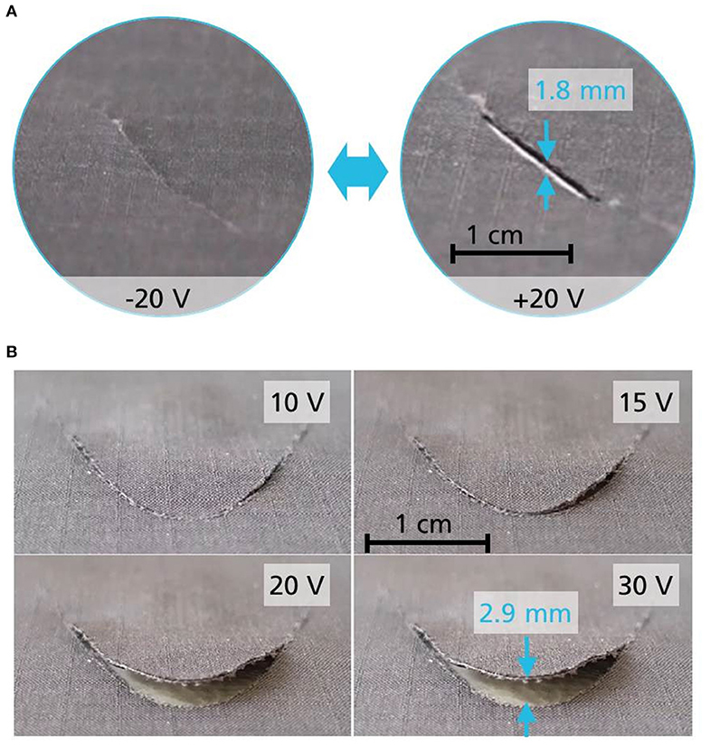
Figure 12. Examples of successfully controlled membrane apertures in (A) the double-curved slit cut demonstrator and (B) the planar flap cut demonstrator.
The same procedure was applied to the second demonstrator with passive flaps. Here again, the first out-of-plane flap deformations were observed at 15 V with no actual separation of the flap from the membrane surface. At the 20 V level six out of 17 flaps produced small openings allowing for air to pass through the membrane while at 30 V all flaps but one visibly bent out of the surface with tip deflections between 2.1 and 3.4 mm. The highest tip deflection of 4.6 mm was measured at 40 V applied to one of the larger flaps located close to the voltage source connector. Some flaps showed a strong bending curvature but did not open because the edges of the parabola shaped cuts in the fabric did not separate due to friction. Upon switching the polarity all previously deformed IEAPs performed a reverse closing motion until they passed the neutral position flush with the membrane surface. Figure 12B shows the actuation behavior of a medium-sized flap at different voltage levels applied to the conductive pathways, generating a 2.9 mm tip deflection at 30 V.
Sensing Properties of Integrated IEAPs
The scenario with a smooth displacement exerted on the membrane flaps with IEAPs attached underneath triggers a voltage signal that is almost perfectly proportional to the displacement, with only minor latency. The output signal is depicted in Figure 13A and goes well in line with the findings of Kamamichi et al. (2007). During the short holding intervals and at neutral displacement position the signal appears more rugged than during the active shifting periods. Furthermore, at neutral position the signal offset increases as it appears to react with a shallower relaxation toward charge equilibrium. This proves that the electrochemical reactions within the IEAP react to the stop of motion in almost real time. The highest measured voltage levels obtained with this test did not exceed 0.1 V for an outward deflection of 4 mm and −0.2 V for an inward deflection of 8 mm. In general, sensors with longer conductive pathways transmitted lower voltage signals compared to sensors closer to the connectors of the measurement device. When they are connected with high-resistance conductive pathways, the increased voltage drop must be taken into consideration for the design and calibration of such membrane sensors.
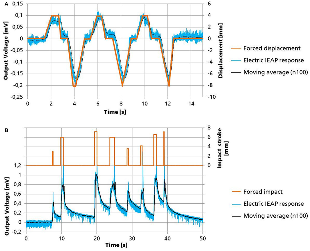
Figure 13. Results of IEAP sensitivity tests. (A) Voltage response obtained from the smooth forced flap displacement scenario with deflections in both inward and outward directions. (B) Voltage response for forced impact and release scenario.
The forced impact scenario depicted in Figure 13B triggers a sharp voltage rise of up to 1 mV at the beginning of the mechanical impacts, followed by a jagged holding period that ends with another sharp spike when the impact stroke is released. After the spike, the voltage level asymptotically decreases as the flaps slowly relax back to their neutral position. Neither the impact stroke nor different holding periods seem to affect the slope of the relaxation curve. The relaxation curve shows about the same rate of decay for all performed impacts, even if the time intervals between impacts vary and one impact interrupts the relaxation phase of the previous impact. This is a sign for robust sensor functionality without hysteresis of such systems.
Life Cycle Assessment Results
The results of the LCA are given in Figure 14. For a realistic assessment of the true energy demand, the calculated CED values for the three stages of production, operation and end-of-life treatment were converted to total primary energy from non-renewable resources (PENRT) values. This was done considering a total energy conversion efficiency of 50% from the caloric energy content of the fuel to the energy output of the power plant. With this in mind, the physical unit of “mega Joules” (CED and PENRT) was converted into the more meaningful unit “kg CO2 equivalents per square meter per year” (CDE and GWP) in consideration of the functional LCA unit being one square meter of membrane element per 1 year of operation for a total impact period of 100 years. The PENRT values are 47.94 MJ/m2a for production, 16.5 MJ/m2a for operation and 0.66 MJ/m2a for end-of-life treatment. The GWP values are 2.58 kg CO2 eq./m2a for production, 1.34 kg CO2 eq./m2a for operation and 0.21 kg CO2 eq./m2a for end-of-life treatment.
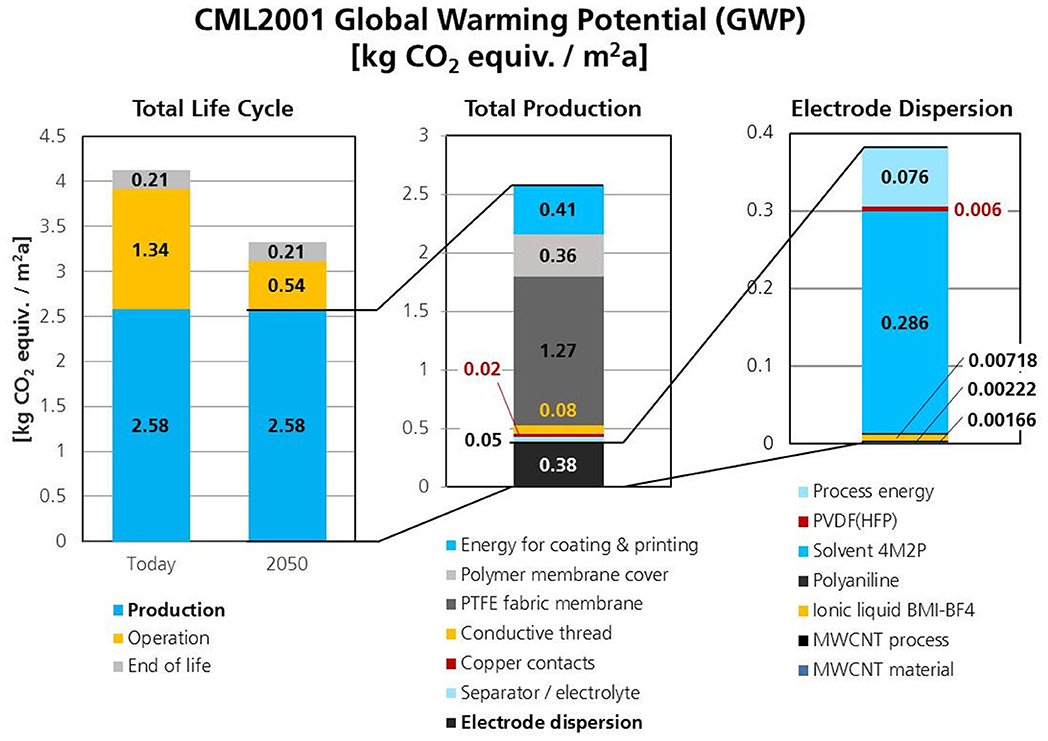
Figure 14. Results of the Life Cycle Analysis (LCA) regarding the energy and material demand required for production, operation and end-of-life treatment of the assembled system. The diagrams show the global warming potential in kilograms of CO2 equivalents per square meter IEAP-enhanced building skin per year.
Discussion
Summary
This article provides information about methods and results regarding the integration of soft and flexible IEAP actuators into planar and double-curved pre-stretched membranes. The scientific goal was to prove that IEAPs are principally capable of generating controllable apertures and to demonstrate that they have a promising potential to provide sensor functionality for adaptive building skins. In this article the complete process chain is described, including benchmarking of IEAP technologies, raw material selection, optimization of dispersion and printing techniques, application-specific post-treatment of IEAPs, system integration methods and automated testing procedures. Industrial manufacturing methods are presented including the adoption of cost-efficient substitute materials and additives that are essential to produce CNT-type IEAP actuators and sensors faster and with better performance reproducibility and enhanced environmental stability. The described simulation assisted design approaches comprise the evaluation and verification of aperture actuation kinematics and the conceptual strategy for the positioning and distribution of actuators.
Evaluation of Actuation Performance
The general actuation behavior of integrated CNT actuators corresponds with the predicted actuation kinematics obtained via simulations. However, for the slit cut apertures of the first demonstrator their overall performance fell short of expectations, and especially the amount of dysfunctional actuators came as a surprise.
The causes of failure are manifold and range from electrode contacts detaching during the first operation cycle, electrode delamination and actuator deterioration due to electric hot spots within the electrode structure all the way to diffusion of heated electrolyte into the contacting threads and short circuits induced by manual handling and integration of actuators. Some of these phenomena such as hot spot generation are well-known from laboratory-scale prototypes and have been reported elsewhere. Other failure phenomena such as diffusion of heated ionic liquid into conductors are specific to this project and − to the best of the authors' knowledge − were encountered for the first time. Regarding actuators that failed during the first operation cycle, the high voltage levels applied to overcome the high contact and line resistances of the conductive pathways proved to be detrimental for some of the actuators. The voltage drop over line and contact resistances is proportional to the electric current flowing through the circuit (and thus through the actuator). Similar to charging a supercapacitor, the initial charging current will quickly decrease as electrochemical double layers form within the actuator electrodes. This decrease in current will cause a smaller voltage drop and consequently much higher given voltage levels at the actuator. Ultimately the voltage level will be much higher than the electrochemical potential window of the ionic liquid permits. Even though the given voltage levels were reduced manually during the actuation period, some actuators were destroyed by overvoltage before any deformation could be observed.
Evaluation of Sensing Performance
The proposed sensing functionalities of IEAPs integrated into membrane skins have been verified. Since the correlations between mechanical input and electric output are known and have now been confirmed, IEAPs might actually pose a viable alternative to other transducers, especially in areas where soft and flexible sensors have an advantage over their rigid and stiff counterparts, for example as health monitoring unit in soft membrane structures. Instead of employing high precision laboratory measurement equipment it is of course desirable to have compact analysis devices that are capable to measure and interpret the small voltage signals generated by deflected IEAPs. Field tests with optimized demonstrators exposed to real wind loads have yet to be conducted. A decline of the sensor functionality over longer operation periods will most likely occur and should be investigated.
Derived Measures for CNT Actuator Optimization and Integration
The authors agree that it is essential to approach potential optimization measures concerning integrated IEAPs in two separate areas: actuator optimization and actuator integration. Regarding the actuator optimization, it is obvious that complex structures such as IEAP will not last forever, due to the decomposition of the polymer matrix and slow evaporation or leakage of electrolytes. As a result, the performance of IEAPs will in most cases decrease over time. The rate of performance drop depends mainly on the number of performed work cycles. This means that IEAPs need to be precisely tailored and optimized to fit their planned application scenario. The ionic liquid BMI-BF4 has been chosen for this project because it provides a wide operational temperature window suitable for building applications. However, other types of ionic liquid have shown greater electrochemical activity and faster ion exchange rates that are more suitable for applications requiring higher actuation displacements and speeds. Optimization measures such as highly impermeable IEAPs encapsulations, force enhancement through actuator stacking and new electrochemically active nano materials and composites are currently explored by the authors and other scientists.
Regarding the actuator integration part, it is self-evident that conductive pathways with much higher electric conductivities are needed to power distributed actuators and sensors. The unpredictable contact resistances and low conductivities of the conductive threads triggered unprecise power settings for the connected IEAPs and resulted in unknown system states. It is essential to transfer sensor signals and electric power more reliably and over much longer distances. Thin copper cables might be a solution with similar automatable handling characteristics (TFP). Furthermore, these conductors should have electrical insulation just as the copper tapes used for integrated electrode contacts in order to shield them from environmental influences. Concerning the parabola shaped flaps in the second demonstrator the friction between the edges needs to be reduced to allow for a smoother and unobstructed opening.
General Evaluation of Potentials and Limitations and Future Outlook
This first-ever experimental approach of using IEAP technology in a building related application has shown that a practicable and reliable integration of such complex electrochemical devices remains a challenge, particularly because their performance is still highly sensitive to many non-application related factors. Material compositions, manufacturing techniques, auxiliary treatments and power controls have to be carefully designed and accurately tailored to yield desired performance characteristics in the first place. The main draw-back of IEAPs is their generally weak force generation, which was again demonstrated by this research. The improvements achieved in performance reproducibility and manufacturability came at a cost of even lower bending forces which probably poses the greatest limitation for most potential future applications. In regards to building applications, the hydrophilicity of the ionic liquids may cause performance degradation over time due to humidity inevitably entering the three layer compound. If engaged for building physical outdoor missions, UV stability is also a topic that still needs to be addressed. Another question that will arise in this context is whether IEAP actuators or sensors will be affected by particle contamination and acidic or basic soiling. Overall, the results obtained for the actuation and sensing capabilities have demonstrated that it is principally possible to use IEAPs for generating controllable apertures in fabric tensile membranes. However, it requires further efforts of optimization to transfer the new discoveries to actual building envelopes.
Nevertheless the authors believe that the technical readiness of IEAPs is constantly improving and that more and more research related to macroscopic applications will emerge within the next few years. Now is the time to intensify the efforts to exploit their unique characteristics and to experiment with them in different areas of technology. They might have particularly high potential in areas where high forces are not required. Actuator arrays could be implemented for morphing indoor surfaces and structures, enabling novel ways of system interaction between users and technical appliances. For years car manufacturers and interior designers have been looking for soft materials that are capable of creating visual or haptic feedback via surface texturing. Once the accuracy and reliability has reached a sufficient state, these transducers may be employed in miniaturized high-precision applications such as optical systems, microscopic sample manipulation and biomedical use cases. The intrinsic sensor properties of IEAPs may promote intelligent fabrics in the field of textile engineering and wearables and provide integrated monitoring functionalities.
Investigations on building related usability of IEAPs in general and CNT based sensors and actuators in particular will be continued by the authors of this manuscript. The interdisciplinary collaboration with architects, process engineers and experts in building physics resulted in a very fruitful and enriching scientific environment with much room for new ideas and great infrastructure for generating and testing hardware. The learning curve has been steep so far, and everyone involved shares one common goal: to accelerate the rugged course toward real-world applications and market adoption of ionic electroactive polymers.
Data Availability Statement
The raw data supporting the conclusions of this article will be made available by the authors, without undue reservation.
Author Contributions
RN: EAP benchmarking, simulation of actuation kinematics, electrical measurements, actuator manufacturing, printing technology, life cycle assessment, and conclusion. NZ: actuator manufacturing, actuator testing, dispersion technology, actuator integration, and electric contact integration. JP: membrane fabrics, architectural input, and soft robotics. YT: introduction and target specification. JS: actuator manufacturing and industrial upscaling. IK: carbon nanotubes and dispersion technology. HD: bioinspired materials, benchmarking, master thesis supervisor, and adaptive architecture. TB: project leader, industrial manufacturing and upscaling, production efficiency, and soft robotics. All authors contributed to the article and approved the submitted version.
Funding
The research presented in this paper was conducted within the framework of the Collaborative Research Center CRC 1244 (SFB1244, sub-project C03) Adaptive skins and structures for the built environment of tomorrow installed at the University of Stuttgart in the year 2017, which is supported by the German Research Foundation (DFG).
Conflict of Interest
The authors declare that the research was conducted in the absence of any commercial or financial relationships that could be construed as a potential conflict of interest.
Acknowledgments
The authors are indebted to the German Research Foundation and all partners that contributed to the development of industrialized dispersion and manufacturing processes of ionic electroactive polymers. A special thanks goes to the Fraunhofer Institute for Manufacturing Engineering and Automation IPA for providing parts of the necessary manufacturing and measurement equipment needed to build and characterize these novel materials. The authors would also like to thank Prof. Dr. Werner Sobek, head of the Institute for Lightweight Structures and Conceptual Design (ILEK) at the University of Stuttgart and Speaker of the CRC 1244 for the exchange of ideas and for providing valuable input regarding architectural standards and building-physical specifications.
References
Abergel, T., Dean, B., and Dulac, J. (2017). Towards a Zero-Emission, Efficient, and Resilient Buildings and Construction Sector. Global Status Report 2017. International Energy Agency; United Nations Environment Programme.
Addinall, R., Sugino, T., Neuhaus, R., Kosidlo, U., Tonner, F., Glanz, C., et al. (2014). “Integration of CNT-based actuators for bio-medical applications — Example printed circuit board CNT actuator pipette,” in International Conference on Advanced Intelligent Mechatronics, (Besacon), 1436–1441.
Aelenei, D., Aelenei, L., and Vieira, C. P. (2016). Adaptive façade: concept, applications, research questions. Energy Proc. 91, 269–275. doi: 10.1016/j.egypro.2016.06.218
Anquetil, P. A., Rinderknecht, D., Vandesteeg, N. A., Madden, J. D., and Hunter, I. W. (2004). “Large strain actuation in polypyrrole actuators,” in: Smart Structures and Materials 2004: Electroactive Polymer Actuators and Devices (EAPAD), ed Y. Bar-Cohen (San Diego, CA), 380. doi: 10.1117/12.540141
Attia, S., Bilir, S., Safy, T., Struck, C., Loonen, R., and Goia, F. (2018). Current trends and future challenges in the performance assessment of adaptive façade systems. Energy Buildings 179, 165–182. doi: 10.1016/j.enbuild.2018.09.017
Baughman, R. H., Cui, C., Zakhidov, A. A., Iqbal, Z., Barisci, J. N., Spinks, G. M., et al. (1999). Carbon nanotube actuators. Science 284, 1340–1344. doi: 10.1126/science.284.5418.1340
Bay, L., West, K., Sommer-Larsen, P., Skaarup, S., and Benslimane, M. (2003). A conducting polymer artificial muscle with 12% linear strain. Adv. Mater. 15, 310–313. doi: 10.1002/adma.200390075
Berardi, U. (2010). Dielectric electroactive polymer applications in buildings. Intellig. Buildings Int. 2, 167–178. doi: 10.3763/inbi.2010.0043
Chang, L., Liu, Y., Yang, Q., Yu, L., Liu, J., Zhu, Z., et al. (2018). Ionic electroactive polymers used in bionic robots: a review. J. Bio. Eng. 15, 765–782. doi: 10.1007/s42235-018-0065-1
Cho, M., Seo, H., Nam, J., Choi, H., Koo, J., and Lee, Y. (2007). High ionic conductivity and mechanical strength of solid polymer electrolytes based on NBR/ionic liquid and its application to an electrochemical actuator. Sens. Actuators B. Chem. 128, 70–74. doi: 10.1016/j.snb.2007.05.032
Cremers, J., Palla, N., Buck, D., Beck, A., Biesinger, A., and Brodkorb, S. (2016). Analysis of a translucent insulated triple-layer membrane roof for a sport centre in Germany. Proc. Eng. 155, 38–46. doi: 10.1016/j.proeng.2016.08.005
Decker, M. (2013). “EMERGENT FUTURES: nanotechology and emergent materials in architecture,” in Conference of Techtonics of Teaching (Newport, UK: Building Technology Educators Society).
Dewidar, K. (2013). “Living Skins: A New Concept of Self Active Building Envelope Regulating Systems. (United Arab emirates).
Fukushima, T., Asaka, K., Kosaka, A., and Aida, T. (2005). Fully plastic actuator through layer-by-layer casting with ionic-liquid-based bucky gel. Angew. Chem. Int. Ed. Engl. 44, 2410–2413. doi: 10.1002/anie.200462318
Haase, W., Klaus, T., Schmid, F., Sobek, W., Sedlbauer, K., Schmidt, T., et al. (2011). Adaptive textile und folienbasierte gebäudehüllen. Bautechnik 88, 69–75. doi: 10.1002/bate.201110005
Habermann, K. J., and Koch, K.-M. (2004). Membrane Structures: Innovative Building With Film and Fabric. Munich: Prestel Publishing Ltd.
Hara, S., Zama, T., Takashima, W., and Kaneto, K. (2004). Artificial muscles based on polypyrrole actuators with large strain and stress induced electrically. Polym. J. 36, 151–161. doi: 10.1295/polymj.36.151
Janssens, A. (1998). Reliable Control of Interstitial Condensation in Lightweight Roof Systems: Calculation and Assessment Methods. Leuven: s.n.
Juaristi, M., Monge-Barrio, A., Knaack, U., and Gómez-Acebo, T. (2018). Smart and Multifunctional Materials and their possible application in façade systems. J. Facade Design Eng. 6, 19–33. doi: 10.7480/jfde.2018.3.2475
Kamamichi, N., Yamakita, M., Asaka, K., Luo, Z.-W., and Mukai, T. (2007). “Sensor property of a novel EAP device with ionic-liquid-based bucky gel,” in: IEEE Sensors, (Atlanta, GA, USA), 221–224.
Kim, B., Mok, B., Ryu, U., Oh, I.-H., Lee, S. K., Cha, S.-E., et al. (2003). “Analysis of mechanical characteristics of the ionic polymer metal composite (IPMC) actuator using cast ion-exchange film,” in Proceedings of SPIE - The International Society for Optical Engineering, Vol. 5051. doi: 10.1117/12.484296
Kim, K., and Shahinpoor, M. (2002). A novel method of manufacturing three-dimensional ionic polymer–metal composites (IPMCs) biomimetic sensors, actuators and artificial muscles. Polymer 43, 797–802. doi: 10.1016/S0032-3861(01)00648-6
Klein, T., and Knaack, U. (2015). Adaptive building envelopes, component development as well as implementation strategies. J. Facade Design Eng. 3:2. doi: 10.7480/jfde.2015.2.1011
Košir, M. (2016). “Adaptive Building envelope: an integral approach to indoor environment control in buildings,” in Automation and Control Trends, eds P. Ponce, A. M. Gutierrez, L. M. Ibarra (InTech), 121–148. doi: 10.5772/64951
Kruusamäe, K., Punning, A., Aabloo, A., and Asaka, K. (2015). Self-sensing ionic polymer actuators: a review. Actuators 4, 17–38. doi: 10.3390/act4010017
Loonen, R. C. G. M., Favoino, F., Rico-Martinez, J. M., and Brzezicki, M. (2015). "Design for façade adaptability: towards a unified and systematic characterization," in 10th Conference on Advanced Building Skins (Bern), 1284–1294.
Melling, D., Martinez, J. G., and Jager, E. W. H. (2019). Conjugated polymer actuators and devices: progress and opportunities. Adv. Mater. Weinheim 31:e1808210. doi: 10.1002/adma.201808210
Mossé, A., Gauthier, D., and Kofod, G. (2012). Towards interconnectivity: appropriation of responsive minimum energy structures in an architectural context. Stud. Mater. Think. 7, 1–11.
Must, I., Kaasik, F., Põldsalu, I., Mihkels, L., Johanson, U., Punning, A., et al. (2015). Ionic and capacitive artificial muscle for biomimetic soft robotics. Adv. Eng. Mater. 17, 84–94. doi: 10.1002/adem.201400246
Nakshatharan, S., Vunder, V., Põldsalu, I., Johanson, U., Punning, A., and Aabloo, A. (2018). Modelling and control of ionic electroactive polymer actuators under varying humidity conditions. Actuators 7:7. doi: 10.3390/act7010007
Neuhaus, R., Bitzer, V., Jablockin, J., Glanz, C., Kolaric, I., Siegert, J., et al. (2019a). “Ionic CNT actuators and arrays – towards cost-efficient manufacturing through scalable dispersion and printing processes,” in 2019 IEEE/ASME International Conference on Advanced Intelligent Mechatronics (AIM) (IEEE), 56–61.
Neuhaus, R., Glanz, C., Kolaric, I., and Bauernhansl, T. (2019b). “Electroactive CNT-polymer-actuators: state of science and technology and their slow approach into architectural applications,” in NanoCarbon Annual Conference, Nanoinitiative Bayern GmbH/Cluster Nanotechnology (Würzburg).
Okuzaki, H., and Funasaka, K. (1999). Electrically driven polypyrrole film actuator working in air. J. Intellig. Mater. Syst. Struct. 10, 465–469.
Paech, C. (2016). Structural membranes used in modern building facades. Proc. Eng. 155, 61–70. doi: 10.1016/j.proeng.2016.08.007
Palmre, V., Torop, J., Arulepp, M., Sugino, T., Asaka, K., Jänes, A., et al. (2012). Impact of carbon nanotube additives on carbide-derived carbon-based electroactive polymer actuators. Carbon 50, 4351–4358. doi: 10.1016/j.carbon.2012.04.071
Park, M., Kim, J., Song, H., Kim, S., and Jeon, M. (2018). Fast and stable ionic electroactive polymer actuators with PEDOT:PSS/graphene-Ag-nanowires nanocomposite electrodes. Sensors 18:3126. doi: 10.3390/s18093126
Plesse, C., Vidal, F., Randriamahazaka, H., Teyssié, D., and Chevrot, C. (2005). Synthesis and characterization of conducting interpenetrating polymer networks for new actuators. Polymer 46, 7771–7778. doi: 10.1016/j.polymer.2005.03.103
Põldsalu, I., Rohtlaid, K., Nguyen, T. M. G., Plesse, C., Vidal, F., Khorram, M. S., et al. (2018). Thin ink-jet printed trilayer actuators composed of PEDOT:PSS on interpenetrating polymer networks. Sens. Actuators B: Chem. 258, 1072–1079. doi: 10.1016/j.snb.2017.11.147
Punning, A., Must, I., Põldsalu, I., Vunder, V., Temmer, R., Kruusamäe, K., et al. (2014). Lifetime measurements of ionic electroactive polymer actuators. J. Intellig. Mater. Syst. Struct. 25, 2267–2275. doi: 10.1177/1045389X14546656
Reichert, S., Menges, A., and Correa, D. (2015). Meteorosensitive architecture: biomimetic building skins based on materially embedded and hygroscopically enabled responsiveness. Comp. Aid Design 60, 50–69. doi: 10.1016/j.cad.2014.02.010
Rinne, P., Põldsalu, I., Johanson, U., Tamm, T., Põhako-Esko, K., Punning, A., et al. (2019). Encapsulation of ionic electromechanically active polymer actuators. Smart Mater. Struct. 28:74002. doi: 10.1088/1361-665X/ab18c0
Roth, S., and Baughman, R. H. (2002). Actuators of individual carbon nanotubes. Curr. Appl. Phys. 2, 311–314. doi: 10.1016/S1567-17390200116-5
Ru, J., Bian, C., Zhu, Z., Wang, Y., Zhang, J., Horiuchi, T., et al. (2019). Controllable and durable ionic electroactive polymer actuator based on nanoporous carbon nanotube film electrode. Smart Mater. Struct. 28:85032. doi: 10.1088/1361-665X/ab2a28
Senatore, G., Duffour, P., and Winslow, P. (2018a). Energy and cost assessment of adaptive structures: case studies. J. Struct. Eng. 144:4018107. doi: 10.1061/ASCEST.1943-541X.0002075
Senatore, G., Duffour, P., and Winslow, P. (2018b). Exploring the application domain of adaptive structures. Eng. Struct. 167, 608–628. doi: 10.1016/j.engstruct.2018.03.057
Senatore, G., Duffour, P., and Winslow, P. (2019). Synthesis of minimum energy adaptive structures. Struct. Multidisc. Optim. 60, 849–877. doi: 10.1007/s00158-019-02224-8
Shahinpoor, M., and Kim, K. J. (2001). Ionic polymer-metal composites: I. Fundamentals. Smart Mater. Struct. 10, 819–833. doi: 10.1088/0964-1726/10/4/327
Shahinpoor, M., Kim, K. J., and Leo, D. J. (2003). Ionic polymer-metal composites as multifunctional materials. Polym. Compos. 24, 24–33. doi: 10.1002/pc.10002
Simaite, A. (2015). Development of Ionic Electroactive Actuators With Improved Interfacial Adhesion: Towards the Fabrication of Inkjet Printable Artificial Muscles. Toulouse: INSA de Toulouse, Micro and nanotechnologies/Microelectronics.
Sobek, W. (2015). Das Triple Zero-Gebäude: Null Energie, Null Emissionen, null Abfall. 15. Münchner Wissenschaftstage: Städte der Zukunft.
Spinks, G. M., Mottaghitalab, V., Bahrami-Samani, M., Whitten, P. G., and Wallace, G. G. (2006). Carbon-nanotube-reinforced polyaniline fibers for high-strength artificial muscles. Adv. Mater. 18, 637–640. doi: 10.1002/adma.200502366
Sugino, T., Kiyohara, K., Takeuchi, I., Mukai, K., and Asaka, K. (2011). Improving the actuating response of carbon nanotube/ionic liquid composites by the addition of conductive nanoparticles. Carbon 49, 3560–3570. doi: 10.1016/j.carbon.2011.04.056
Sung, D. K. (2011). “Skin deep: making building skins breathe with smart thermobimetals,” in Where do you stand: 99th ACSA annual meeting, March 3-6, 2011, Montréal, Canada, eds A. Pérez Gómez, A. Cormier, and A. Pedret (Washington, DC: ACSA Press, 145–152.
Tamagawa, H., Okada, K., Mulembo, T., Sasaki, M., Naito, K., Nagai, G., et al. (2019). Simultaneous enhancement of bending and blocking force of an ionic polymer-metal composite (IPMC) by the active use of its material characteristics change. Actuators 8:29. doi: 10.3390/act8010029
Tang, T., Yang, D.-H., Wang, L., Zhang, J.-R., and Yi, T.-H. (2019). Design and application of structural health monitoring system in long-span cable-membrane structure. Earthq. Eng. Eng. Vib. 18, 461–474. doi: 10.1007/s11803-019-0484-y
Tauber, M., Feldkamp, D., Christian, G., Ailke, H., Till, Z., and Tobias, S. (2019). Building the Housing of the Future. Munich: Boston Consulting Group.
Terasawa, N. (2017). High-performance ionic and non-ionic fluoropolymer/ionic liquid gel hybrid actuators based on single-walled carbon nanotubes. RSC Adv. 7, 2443–2449. doi: 10.1016/j.matpr.2019.10.044
United Nations (2017). World Population Prospects: The 2017 Revision: Key Findings and Advance Tables. New York, NY: United Nations.
Vidal, F., Plesse, C., Palaprat, G., Juger, J., Citerin, J., Kheddar, A., et al. (2008). Synthesis and characterization of IPNs for electrochemical actuators. AST 61, 8–17. doi: 10.4028/www.scientific.net/AST.61.8
Vunder, V., Punning, A., and Aabloo, A. (2012). Mechanical interpretation of back-relaxation of ionic electroactive polymer actuators. Smart Mater. Struct. 21:115023. doi: 10.1088/0964-1726/21/11/115023
Keywords: electroactive polymer (EAP) actuators, adaptive building envelope, integration concepts, switchable breathability, smart material actuator, wind load sensing, ventilation
Citation: Neuhaus R, Zahiri N, Petrs J, Tahouni Y, Siegert J, Kolaric I, Dahy H and Bauernhansl T (2020) Integrating Ionic Electroactive Polymer Actuators and Sensors Into Adaptive Building Skins – Potentials and Limitations. Front. Built Environ. 6:95. doi: 10.3389/fbuil.2020.00095
Received: 27 March 2020; Accepted: 27 May 2020;
Published: 02 July 2020.
Edited by:
Gennaro Senatore, École Polytechnique Fédérale de Lausanne, SwitzerlandReviewed by:
Paolo Milani, University of Milan, ItalyRoel Loonen, Eindhoven University of Technology, Netherlands
Alvo Aabloo, University of Tartu, Estonia
Copyright © 2020 Neuhaus, Zahiri, Petrs, Tahouni, Siegert, Kolaric, Dahy and Bauernhansl. This is an open-access article distributed under the terms of the Creative Commons Attribution License (CC BY). The use, distribution or reproduction in other forums is permitted, provided the original author(s) and the copyright owner(s) are credited and that the original publication in this journal is cited, in accordance with accepted academic practice. No use, distribution or reproduction is permitted which does not comply with these terms.
*Correspondence: Raphael Neuhaus, cmFwaGFlbC5uZXVoYXVzQGlmZi51bmktc3R1dHRnYXJ0LmRl