 Pei-Ching Chen
 Meng-Wei Dong1
 Narutoshi Nakata
- 1Adavance Experimental Technology Laboratory, Department of Civil and Construction Engineering, National Taiwan University of Science and Technology, Taipei, Taiwan
- 2Department of Civil and Environmental Engineering, Tokushima University, Tokushima, Japan
The building mass damper (BMD) system, which incorporates the concept of a tuned mass damper into a mid-story isolation system, has been demonstrated as an effective system for suppressing structural vibration due to earthquakes. The BMD system separates a building into a substructure, a control layer and a superstructure. By applying well-design parameters, the seismic responses of the superstructure and substructure of a building can be mitigated simultaneously. However, merely limited design parameters have been verified by shaking table testing because it is difficult to construct several sets of specimens with limited research funding. Therefore, real-time hybrid simulation (RTHS) may become an alternative to conduct parametric studies of the BMD system efficiently and economically. In this study, the BMD system is separated into a numerical substructure and an experimental substructure. The experimental substructure includes the control layer and the superstructure of the BMD system installed on a seismic shake table while the substructure is numerically simulated. Then, substructuring method of the BMD system is derived and the stability analysis considering the dynamics of the shake table is performed to realize the potential feasibility of RTHS for BMD systems. The stability margin is represented as an allowable mass ratio of the experimental substructure to the entire BMD system. Finally, RTHS of a simplified BMD system has been conducted to verify the stability margin in the laboratory. Phase-lead compensation and force correction are applied to RTHS in order to improve the accuracy of RTHS for the simplified BMD system.
Introduction
A novel structural system named as building mass damper (BMD) system, which combines the advantages of seismic isolation and tuned mass damper design has been proposed and studied. A BMD system is composed of a substructure, a control layer and a superstructure. Conventionally, the mass of the superstructure above the control layer can be designed as a tuned mass, becoming an energy absorber to suppress the response of the substructure. This system is also called partial mass isolation technique, or large-mass ratio tuned mass damper (TMD), and has been extensively studied by many researchers for the past decades. Matta and De Stefano (2009) developed the concept of the roof-garden TMD and explored the mass ratio effect on the performance of seismic mitigation. De Angelis et al. (2012) performed shake table testing of a large mass ratio TMD and a reduced order model was proposed for optimal design for seismic applications. Anajafi and Medina (2018) analyzed the performance of partial mass isolation and compared it to conventional TMD and base isolation system for different soil conditions through numerical simulation. For special application, De Domenico and Ricciardi (2018b) applied the base isolation incorporated with a large mass ratio TMD located at the basement. Meanwhile, De Domenico and Ricciardi (2018a) proposed an inerter-based vibration absorber combined with base isolation systems and performed parametric optimization considering different objective functions. The aforementioned researches explored the seismic performance of structures with various layout and allocation of isolation system and mass damper.
In recent years, the occupancy of the superstructure has been also considered in the design optimization of a BMD system (Wang et al., 2018). In the optimization process, a BMD system was represented by a simplified three degrees-of-freedom (3DOF) lumped mass structure model, composed of a superstructure, a control layer, and a substructure. By minimizing the sum of differences between each two modal damping ratios, the optimal design parameters of a BMD system can be obtained. After determining the mass and natural frequency of the substructure, a total number of seven parameters can be designed for a BMD system including the frequency ratios of the control layer and superstructure with respect to the fundamental frequency of the substructure, mass ratios of the control layer and superstructure with respect to the mass of the substructure, and the damping ratios of the superstructure, control layer, and substructure. Design parameters of the BMD system were verified by conducting shake table testing. Experimental results indicated that the seismic performance of the BMD system is strongly related to the frequency content of seismic excitation. Unfortunately, further experimental validation considering various design parameters as well as structural non-linearity remain empty because the shake table test was not repeatable as long as the specimen behaved non-linearly. Replacing the steel specimen could be time-consuming and costly. As a result, real-time hybrid simulation (RTHS) could be adopted to investigate the seismic responses of BMD systems when parametric studies are needed with expected non-linear behavior.
RTHS which combines structural testing with numerical simulation is an advanced, efficient and cost-effective experimental method for earthquake engineering studies to explore the structural response due to dynamic excitation. In a RTHS, a structure is separated into at least an experimental substructure and a numerical substructure. The interfacial degrees of freedom between the experimental and numerical substructures are represented by servo-hydraulic actuators and mechanical fixtures. A step-by-step integration algorithm is required to solve the response at the interfacial degrees of freedom of the numerical substructure subjected to excitation. This response is imposed on the experimental substructure in real time through a servo-hydraulic system. The corresponding response is then measured from the experimental substructure and fed back to numerical substructure to compute the interfacial response for the next time step until the RTHS is completed. In particular, seismic shake tables can be adopted as the interface between numerical and experimental substructures which enables seismic simulation of multi-story shear buildings in a way that the upper part of a building can be experimentally tested on the table while the rest part of the building can be numerically modeled. In this approach, the seismic shake table must track the absolute acceleration at the interfacial degrees of freedom when the numerical substructure is subjected to earthquakes. The inertial forces of the experimental substructure then can be accurately represented. However, significant vibrating mass in the experimental substructure could result in the difficulties of tracking the acceleration computed from the numerical substructure, leading to the so-called control-structure interaction (Dyke et al., 1995). As a result, control analysis and synthesis have been conducted in order to achieve accurate RTHS using seismic shake table (Nakata and Stehman, 2014; Zhang et al., 2016). Currently, limited research topics have been studied by employing RTHS with shake table, such as tuned liquid damper system (Wang et al., 2016), mid-level isolation (Schellenberg et al., 2017), and semi-active mass damper system (Chu et al., 2018).
It is expected that RTHS could become an effective alternative to investigate the seismic performance of a BMD system with numerous structural parameters. During a RTHS, the substructure can be simulated numerically while the control layer and superstructure can be tested physically on a seismic shake table. In this study, substructuring of the equation of motion is derived first and stability analysis procedure is proposed to evaluate the feasibility of reproducing the experimental results of the BMD system that was previously tested on a shake table through RTHS. The stability margin is represented as an equivalent allowable mass ratio of the experimental substructure to the entire BMD system. This stability analysis method provides potential users with a rapid and simple approach to evaluate the feasibly of RTHS using a shake table. The stability analysis results are discussed and summarized. Finally, RTHS of a simplified BMD system is conducted in the laboratory. Phase-lead compensation (PLC) and force correction (FC) methods are applied to RTHS in order to improve the accuracy of RTHS. Finally, experimental results are discussed and compared with a benchmark BMD system. Experimental results demonstrate that the stability analysis is instrumental in understanding the theoretical stability margin of RTHS before it is conducted. Besides, the PLC and FC are effective in improving the RTHS results.
Substructuring of a BMD System
A BMD system can be simplified by a 3DOF structure model in the design stage which includes a superstructure, a control layer, and a substructure as shown in Figure 1. When a BMD system is subjected to ground motion, its equation of motion can be expressed as
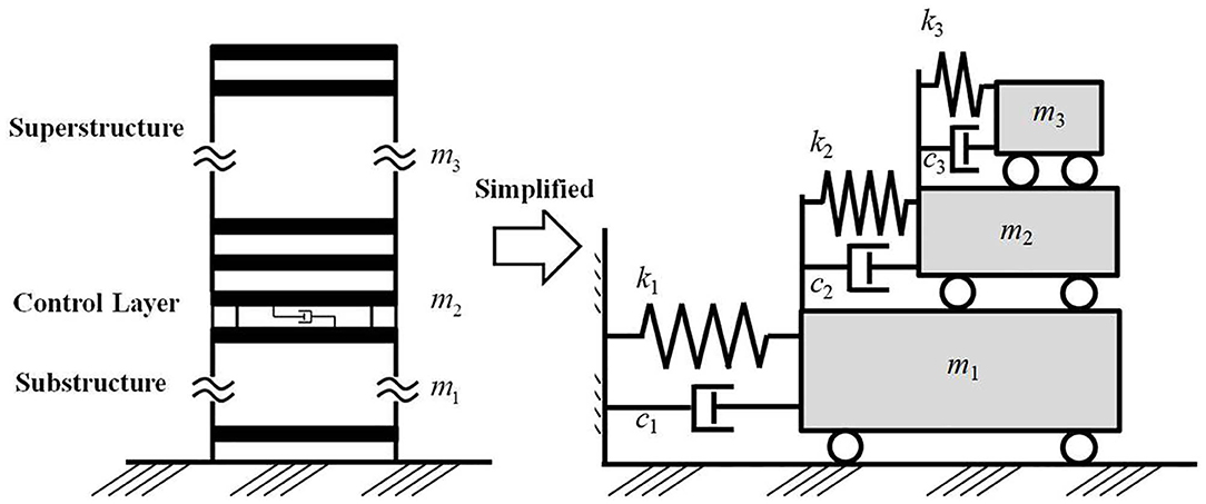
Figure 1. Simplified 3DOF structure model of a BMD system.
where M, C, and K are the mass, damping coefficient and stiffness matrices, respectively; u is the relative displacement vector; l is the earthquake excitation influence vector in which all elements are unity; and üg(t) is the ground acceleration. For a BMD system, M, C, and K can be expressed as
where m1, m2, and m3 are the mass of the substructure, control layer, and superstructure, respectively; c1, c2, and c3 are the damping coefficient of the substructure, control layer, and superstructure, respectively; and k1, k2, and k3 are the lateral stiffness of the substructure, control layer, and superstructure, respectively.
During a RTHS, the BMD system can be separated into an experimental substructure and a numerical substructure as depicted in Figure 2. The experimental substructure contains the control layer and superstructure that is tested physically on a seismic shake table, while the substructure is numerically simulated. The equation of motion of a BMD system shown in Equation (1) can be modified by considering the numerical and experimental substructures as
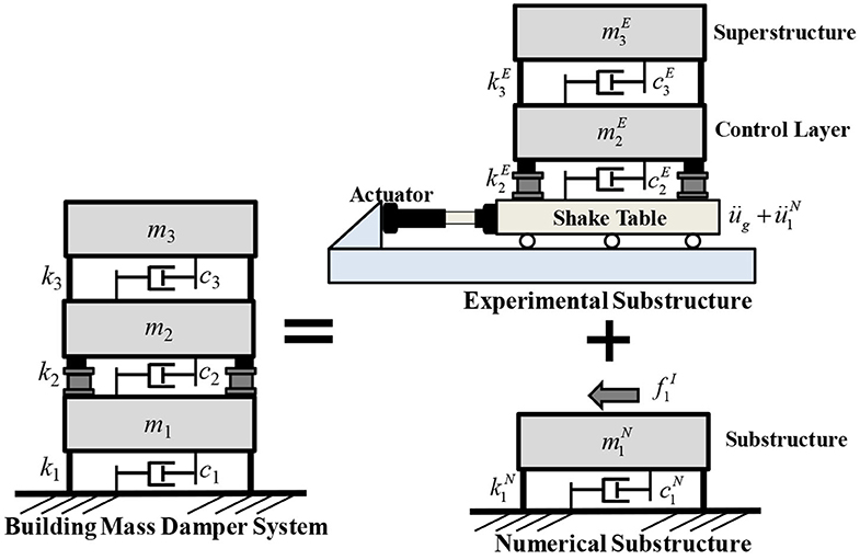
Figure 2. Illustration of the substructuring for RTHS of a BMD system.
The superscript N represents the contribution of the numerical substructure; the superscript E represents the contribution of the experimental substructure; and the superscript I represents the interfacial degree of freedom. Only the equation of motion of the numerical substructure is solved by applying step-by-step integration algorithm as
where represents the shear force transmitted from the experimental substructure to the numerical substructure at the interfacial degree of freedom. Since the platen of shake table can be regarded as the interfacial degree of freedom, the response of the control layer and the superstructure is relative to the platen of shake table. By letting and , the equation of motion of the experimental substructure can be expressed as
Finally, the transmitted shear force can be derived as:
It is obvious that the transmitted shear force can be obtained by the inertial force of the experimental substructure. In practice, the measurement of accelerometers could contain noise. Therefore, Kalman filter can be applied to estimate the absolute acceleration at each floor of the experimental substructure. The inertial force at each floor can be obtained by multiplying the estimated absolute acceleration by the lumped mass. Then, the transmitted shear force can be calculated by summing the inertial force of each floor. Alternatively, load cells can be installed between the control layer and the shake table to measure the transmitted shear force directly.
Stability Analysis Method
In the study, RTHS of a BMD system forms a closed loop between the numerical substructure, seismic shake table, and experimental substructure. Figure 3 illustrates the linking between each component in the RTHS. The ground motion üg is input to the numerical substructure and the transmitted absolute acceleration response () at the interfacial degree of freedom needs to be reproduced by the shake table. In other words, the experimental substructure is subjected to the transmitted absolute acceleration. Inevitably, the achieved acceleration of the shake table () is different from the desired acceleration due to the dynamics of the shake table. The shear force is then measured by load cells or calculated by a Kalman filter, and fed back to the numerical substructure and complete the RTHS closed loop. Noted that a Kalman filter may be necessary for the RTHS loop in order to prevent measurement noise from being introduced to the numerical substructure and leading to spurious command to the shake table.
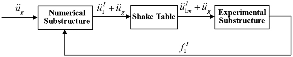
Figure 3. Block diagram of RTHS for a BMD system.
The stability of a RTHS loop can be investigated from the perspective of transfer function as shown in Figure 4 in which s is the Laplace complex number. From Equation (4), it can be seen that the acceleration relative to the ground is contributed from the ground acceleration and the transmitted shear force from the experimental substructure. Therefore, the transfer function from the ground acceleration to the absolute acceleration at interfacial degree of freedom is denoted as . Meanwhile, the relative acceleration at the top of the numerical substructure due to the transmitted shear force is denoted as üs. The desired absolute acceleration () is obtained and sent to the seismic shake table Gs(s). The achieved acceleration () excites the experimental substructure and the corresponding shear force can be obtained. Therefore, the transfer function from the input excitation of the experimental substructure to the shear force at the interfacial degree of freedom can be represented as . This shear force is converted to the relative acceleration üs to the numerical substructure by the transfer function . Finally, the corresponding closed-loop transfer function of the RTHS from the ground acceleration to the achieved acceleration of the shake table becomes:
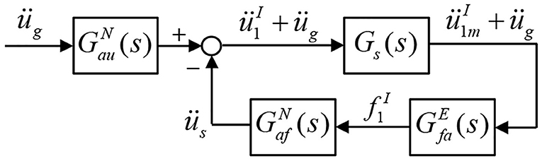
Figure 4. Closed loop transfer function of RTHS for a BMD system.
The RTHS stability can be investigated by solving the characteristic equation in the denominator. Noted that the effect of integration algorithm and system uncertainty of shake table are not considered in the stability analysis in this study. It can be found in Equation (7) that the transfer functions related to the experimental and numerical substructures are dependent on the structural parameters, i.e., mass, damping coefficient, and stiffness. Since the interaction between the experimental and numerical substructures is the transmitted shear force , which is associated with the mass of the experimental substructure as indicated in Equation (6). As a result, the allowable mass ratio is adopted as a stability index for RTHS of BMD systems which is defined as:
where mE and mN are the effective modal mass of the dominant mode of the experimental and numerical substructures, respectively. With determined modal frequencies and damping ratios of the experimental and numerical substructures, the allowable mass ratio of the closed-loop RTHS can be obtained.
Demonstrative Example
Experimental Setup
In the first stage, the stability analysis regarding the mass ratio of the experimental substructure to the entire BMD structural system was performed. The BMD system for demonstrative purposes is identical to one of the BMD systems tested by Wang et al. (2018). The entire BMD specimen was an 8-story steel structure model with single-bay widths of 1.1 and 1.5 m in the longitudinal and lateral directions, respectively. The substructure contained the three stories from the bottom and the superstructure included the four stories from the top. The control layer was located at the fourth floor. It is noted that the experimental substructure for the RTHS merely consisted of the control layer and the superstructure. Each floor was 1.1 m high, and each slab was 20 mm thick. The columns and beams were wide flange with a sectional dimension of 100 × 100 × 6 × 8 (mm). Four elastomeric bearings with a diameter of 180 mm and two linear fluid viscous dampers were installed at the control layer. Two sets of steel blocks with a mass of 0.25 kN-s2/m were installed regularly at each floor to simulate the mass. Considering the mass contribution from the columns and slab, the lumped mass for the control layer and each story of the superstructure was 0.76 and 0.8 kN-s2/m, respectively. The experimental substructure was installed on a uni-axial shake table in the structural laboratory of the National Center for Research on Earthquake Engineering (NCREE) in Taiwan. The uni-axial shake table was operated by using a FlexTest GT controller manufactured by MTS Systems Corporation with well-tuned proportional and integral gains. The maximum stroke and force capacity of the actuator were ±250 mm and ±500 kN, respectively. Two linear-position sensors, Temposonics, were installed in the longitudinal direction of the shake table. The displacement of the shake table was obtained by taking the average of the two measurements. Furthermore, six accelerometers were installed on the shake table and each floor of the experimental substructure to measure the corresponding absolute accelerations. A dSPACE MicroLabBox, an integrated system which has more than 100 input/output channels of different types was utilized to run the numerical substructure as it can be simply interfaced with MATLAB and Simulink. The Simulink-based equation of motion of the numerical substructure can be converted to real-time C code, compiled and downloaded to the MicroLabBox, achieving real-time measurement data collection and integration algorithm computation. Meanwhile a commercial graphical user interface software, ControlDesk was implemented to monitor the responses online during RTHS. The experimental setup is shown in Figure 5.
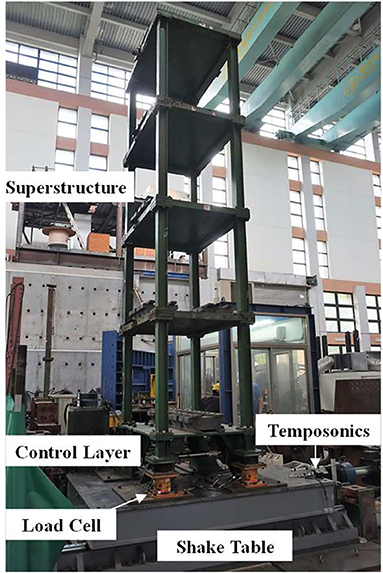
Figure 5. Experimental setup of the experimental substructure of the 8-story BMD system.
Stability Analysis
In the RTHS, the substructure was numerically modeled using a non-linear real-time structural analysis software “RTFrame2D” (Castaneda-Aguilar et al., 2012). The first modal natural frequency of the numerical substructure, denoted as ωN, was 35.43 rad/s. The modal damping ratio of the numerical substructure was assumed 2%. On the other hand, system identification was conducted in order to identify the structural parameters of the experimental substructure. The root-mean-square of accelerometer measurement noise was 0.0524 m/s2. The first modal natural frequency of the experimental substructure was 17.72 rad/s, and the damping ratio was 2.8%. Noted that the mass ratio indicated in Equation (8) for this 8-story BMD system was 0.65 for this BMD system. The dynamics of the shake table with the experimental substructure can be also identified by conducting system identification testing. The identified transfer function between the acceleration command to the achieved acceleration is
Figure 6 shows the transfer function of the shake table with experimental substructure and the corresponding identified model. It can be seen that both the magnitude and phase of the model fit the transfer function well within the frequency of interest. Meanwhile, there is strong interaction at 8.98 Hz which is the 2nd modal frequency of the experimental substructure. By considering the dynamics of the shake table G(s), the stability margin in terms of the allowable mass ratio can be obtained as shown in Figure 7. Since ωN, was 35.43 rad/s and the mass ratio for the 8-story BMD substructuring was 0.65, RTHS for this BMD system was unstable if compensation methods were not applied.
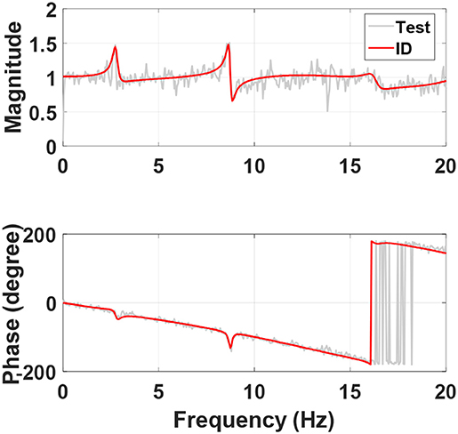
Figure 6. System identification of the shake table with the experimental substructure.
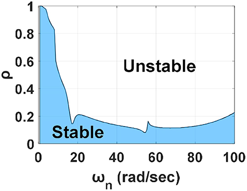
Figure 7. Stable margin considering shake table dynamics for RTHS of the 8-story BMD system.
Delay Compensation
Generally, delay compensation is essential to completing successful RTHS as time delay between the desired and achieved response at the interfacial degree of freedom introduce negative damping into RTHS, which would result in inaccuracies and potential instabilities. The discrete phase-lead compensator (PLC) proposed by Chen and Tsai (2013) was adopted to compensate the dynamics of the shake table in the demonstrative example which can be expressed as
where W1 and W2 are the weightings which has to be located in the stable regions; and z is a complex number in the z transform. In the demonstrative example, both W1 and W2 were set 2. Meanwhile, the delay constant α can be determined by the phase plot as shown in Figure 6. The phase lag can be approximated to a constant delay time of 26 ms, which is equal to 5 time steps when the sampling rate of RTHS was 200 Hz (α = 5).
For the BMD substructuring, perfect compensation leads to accurate achieved acceleration of the shake table. Due to the sequential architecture of RTHS as shown in Figure 3, perfect compensation results in shear force response from the experimental substructure with one-step time delay that is fed back to the numerical substructure. By assuming that the acceleration tracking control of the shake table was perfect but with one step of delay (0.005 s for example), the corresponding stability margin in terms of the allowable mass ratio can be obtained as shown in Figure 8. It can be seen that the mass ratio of the 8-story BMD system (0.65) is very close to the stable margin which was obtained by assuming a perfect shake table that was able to reproduce the absolute acceleration at the top of the numerical substructure. However, this allowable mass ratio drops significantly when the dynamics of the shake table is considered as shown in Figure 7. Conclusively, it was considered extremely difficult to conduct RTHS of the 8-story BMD system even appropriate delay compensation was applied. Moreover, RTHS of the 8-story BMD system was only stable when the shear force fed back to the numerical substructure was reduced to 30% or less in this demonstrative example. In other words, the mass ratio in Equation (8) was changed from 0.65 to 0.2 or less. From the stability margin shown in Figure 7, the allowable mass ratio considering the shake table dynamics without compensation is around 0.15. It indicates that the PLC was helpful to increasing the allowable mass ratio for the BMD system (from 0.15 to 0.2); however, the improvement was considered limited. In summary, it was extremely difficult to complete stable RTHS for the BMD system which was identical to the one tested by Wang et al. (2018). As a result, a simplified BMD system became an alternative for RTHS demonstration in which the mass ratio was smaller than but close to the allowable mass ratio.
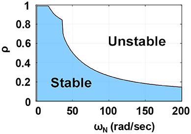
Figure 8. Stable margin in terms of mass ratio for RTHS of BMD systems with perfect compensation.
RTHS of a Simplified BMD System
Design Parameters
The simplified BMD system was a 3DOF structure which was identical to the illustration as shown in Figure 2. After removing three stories from the experimental substructure of the 8-story BMD system, the experimental substructure of the simplified BMD system only contained the control layer and one-story superstructure while the one-story substructure was numerically simulated. The experimental setup is shown in Figure 9. The identified natural frequencies of the experimental substructure were 5.94 and 19.21 Hz. The damping ratio of the first two modes were 2.14 and 1.24%. The structural parameters of the experimental substructure are shown in Table 1. The transfer function of the shake table with the experimental substructure is depicted in Figure 10. The update rate of the RTHS was 200 Hz. It can be found that the phase lag can be approximated to a constant delay time of 25 ms which is equal to 5 time steps. In other words, the PLC in the RTHS of the simplified BMD system was identical to the one used for the 8-story BMD system previously.
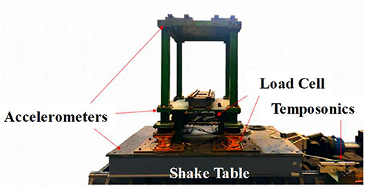
Figure 9. Experimental setup of the experimental substructure of the simplified BMD system.
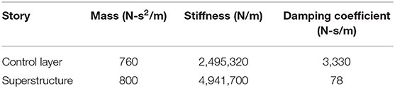
Table 1. Identified structural parameters of the experimental substructure.
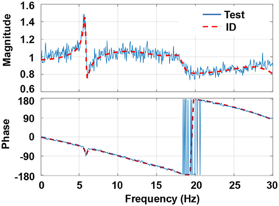
Figure 10. System identification of the shake table with the experimental substructure of the simplified BMD system.
According to the design suggestions for BMD systems from Wang et al. (2018), the substructure was designed with a natural frequency of 14.98 Hz (94.09 rad/s) and a damping ratio of 1.67%. Accordingly, the natural frequency of the substructure was about 2.5 times of the first modal frequency of the experimental substructure. By following the aforementioned procedure, the stability margin in terms of the allowable mass ratio can be obtained as shown in Figure 11. It can be found that the allowable mass ratio of RTHS for the simplified BMD was 0.2 because ωN was 94.09 rad/s. The effective modal mass of the experimental substructure was 1.53 kN-s2/m, which can be calculated based on the identified structural parameters. Accordingly, the mass of the numerical substructure was set as 8 kN-s2/m, which gave a mass ratio close to the stability margin of RTHS.
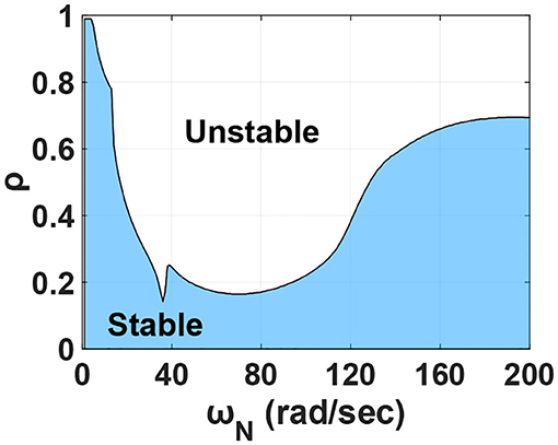
Figure 11. Stable margin considering shake table dynamics for RTHS of the simplified BMD system.
Force Correction Method
In addition to delay compensation, a force correction method is proposed in this study in order to improve the accuracy of RTHS. In the architecture of RTHS for BMD systems as shown in Figure 3, the response at the interfacial degree of freedom at the i-th time step is obtained by solving the equation of motion of the numerical substructure and becomes the input to the experimental substructure. The resulted base shear measured from the experimental substructure is input to the numerical substructure at the i + 1-th step. As mentioned previously, there is one-step delay between the numerical and experimental substructures inevitably even perfect acceleration tracking is achieved. In fact, the equation of motion is not satisfied due to the imperfect interfacial connection between the experimental and numerical substructures in real practice including the dynamics of shake table, experimental boundary condition, modeling error and etc. Thus, the unbalanced force at each time step leads to significant inaccuracy of RTHS which is generally referred to as error propagation. As a result, the force correction method compares the force balance at each time step and the unbalanced force is corrected at the next time step to prevent the RTHS from error propagation. The force correction method calculates the correction force fc as
The correction force is used to correct the transmitted shear force error due to the difference between the desired and achieved acceleration at the interfacial degree of freedom. Figure 12 illustrates the block diagram of the RTHS of the simplified BMD system with both phase-lead compensation and force correction.
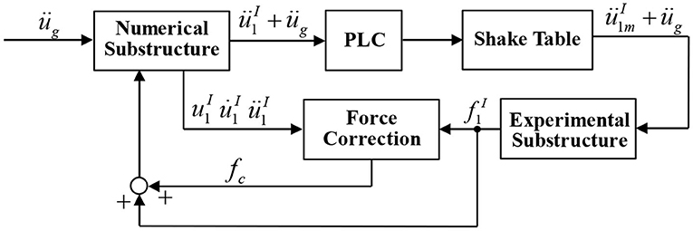
Figure 12. Block diagram of the RTHS for the simplified BMD system.
Experimental Results
A total of 13 earthquakes normalized to a peak ground acceleration of 1.0 m/s2 were used as the excitation to the BMD system. A 3DOF numerical model with the same structural parameters was adopted as the benchmark for comparison purposes. The RTHS results were compared with the benchmark results by employing the root-mean-square error (RMSE) of the acceleration at each floor between the RTHS and the benchmark. The RMSE is defined as
where ü[k] and üRTHS[k] are the absolute acceleration at each floor of the BMD system from the benchmark and RTHS at the kth step, respectively; and Ns is the total step number of the RTHS. Four compensation schemes were applied including uncompensated (UC), force correction (FC), PLC, and PLC + FC. Tables 2, 3 show the RMSE of the superstructure and substructure, respectively. It can be found that FC merely slightly improves the acceleration response at the substructure when it is compared with the uncompensated scheme. However, FC is not able to prevent RTHS from becoming unstable when the BMD system is subjected to the Christchurch ground acceleration because the frequency components of the Christchurch ground acceleration are higher than those of the other earthquakes. On the contrary, the implementation of PLC reduces the RMSE significantly compared with the uncompensated case and also achieves stable RTHS for the case with Christchurch ground excitation. Moreover, the RMSE is further reduced almost for all earthquake cases when the PLC is combined with FC, demonstrating that the PCL + FC is effective on achieving better RTHS results. Meanwhile, it seems that FC is more effective on reducing the RMSE of the acceleration response at the superstructure (experimental substructure) compared with that at the substructure (numerical substructure). It is also observed that even if the mass ratio of the experimental substructure to the entire BMD system is smaller than but close to the allowable mass ratio, RTHS could still become unstable considering the modeling error and system uncertainty. Therefore, compensation is essential to achieve more accurate and stable RTHS for BMD systems. In summary, PLC is more effective on reducing the RMSE of the acceleration response at the substructure than FC. However, PLC does not necessarily achieve more accurate response than FC does for the experimental substructure. It is suggested that both delay compensation and force correction are applied to RTHS of the BMD system for obtaining reasonable experimental results. Figure 13 shows the acceleration response of the superstructure obtained from RTHS (PLC + FC) and the benchmark when the BMD system was subjected to the Parkfield excitation. It appears that the RTHS response was slightly larger than the benchmark response; however, the peak responses were considered fairly well. Future studies will be focused on the acceleration tracking control of shake table in order to further reduce the RMSE of RTHS.

Table 2. RMSE of the substructure acceleration response with various compensation schemes.
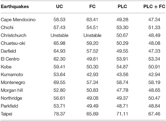
Table 3. RMSE of the superstructure acceleration response with various compensation schemes.
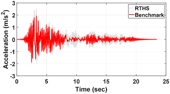
Figure 13. Acceleration time histories of the superstructure from RTHS and benchmark.
Conclusions
A building mass damper (BMD) system which decomposes of a building into a substructure, a control layer and a superstructure, aiming to reduce the seismic response of the superstructure and substructure simultaneously by tuning structural parameters of the BMD system. Shake table testing provides an effective and straightforward approach to evaluate the seismic mitigation performance of a BMD system; however, repeated testing is not expectable when the experimental specimen of a BMD system behaves non-linearly under the earthquake excitation. For parametric studies of BMD systems, it could be costly to replace the specimens. As a result, real-time hybrid simulation (RTHS), which combines numerical simulation with structural testing could become an alternative approach to conduct parametric studies of BMD systems in a timely and cost-effective manner. In particular, RTHS using a seismic shake table is expected as the design of parameters for a BMD system merely considers the horizontal direction parallel to earthquake ground acceleration. Hence, a seismic shake table can be adopted as the interfacial degree of freedom between numerical and experimental substructures. In this study, stability analysis method for RTHS of a BMD system has been proposed and verified through conducting experiments in the laboratory.
In the stability analysis method, a BMD system can be simplified as a 3DOF structural model. Since the shear force from the experimental substructure related to the mass is transmitted to the numerical substructure; therefore, the stability margin is represented as a mass ratio of the effective modal mass of the dominant mode of the experimental substructure to that of the numerical substructure and the experimental substructure. Stability analysis results indicate that it is challenging to conduct RTHS of a typical BMD system in which the mass of the superstructure is larger than that of the substructure even when delay compensation is applied. However, stable and successful RTHS can be achieved as long as the mass ratio is small and the first natural frequency of the substructure is low. In order to achieve more accurate RTHS, force correction method is proposed which is based on the unbalanced equation of motion of the numerical substructure. The force correction calculates the unbalanced force at the current time step and compensates the force at the next time step. Experimental results demonstrate that delay compensation is helpful to increasing the allowable mass ratio of a BMD system in RTHS; however, force correction is not. Meanwhile, delay compensation is more effective on reducing the root-mean-square error of the acceleration response at the numerical substructure than the force correction. However, it is not necessarily valid for the experimental substructure. Furthermore, force correction with delay compensation significantly reduces the root-mean-square error of the acceleration response at the numerical substructure. As a result, it is suggested that both delay compensation and force correction are required to RTHS of BMD systems not only for improving the experimental accuracy but also for increasing the allowable mass ratio for stable and successful RTHS.
Data Availability Statement
The raw data supporting the conclusions of this article will be made available by the authors, without undue reservation.
Author Contributions
Pe-CC: journal paper document, data analysis, and project supervision. M-WD: RTHS experiments and stability analysis. Po-CC: data analysis. NN: project supervision. All authors contributed to the article and approved the submitted version.
Funding
This study was supported by the Collaboration Program between Tokushima University and National Taiwan University of Science and Technology (TU-NTUST-107-04). The APC was funded by the Taiwan Building Technology Center from The Featured Areas Research Center Program within the framework of the Higher Education Sprout Project by the Ministry of Education in Taiwan.
Conflict of Interest
The authors declare that the research was conducted in the absence of any commercial or financial relationships that could be construed as a potential conflict of interest.
Acknowledgments
The experiments were conducted in the laboratory of National Center for Research on Earthquake Engineering (NCREE) in Taiwan. The authors would like to thank all the technical support from NCREE.
References
Anajafi, H., and Medina, R. A. (2018). Comparison of the seismic performance of a partial mass isolation technique with conventional TMD and base-isolation systems under broad-band and narrow-band excitations. Eng. Struct. 158, 110–123. doi: 10.1016/j.engstruct.2017.12.018
Castaneda-Aguilar, N. E., Gao, X., and Dyke, S. J. (2012). RT-Frame2D: a computational platform for the real-time hybrid simulation of dynamically-excited steel frame structures. J. Comput. Civil. Eng. 29:04014049. doi: 10.1061/(ASCE)CP.1943-5487.0000341
Chen, P. C., and Tsai, K. C. (2013). Dual-compensation strategy for real-time hybrid testing. Earthq. Eng. Struct. Dyn. 42, 1–23. doi: 10.1002/eqe.2189
Chu, S. Y., Lu, L. Y., and Yeh, S. W. (2018). Real-time hybrid testing of a structure with a piezoelectric friction controllable mass damper by using a shake table. Struct. Control Health Monitor. 25:e2124. doi: 10.1002/stc.2124
De Angelis, M., Perno, S., and Reggio, A. (2012). Dynamic response and optimal design of structures with large mass ratio TMD. Earthq. Eng. Struct. Dyn. 41, 41–60. doi: 10.1002/eqe.1117
De Domenico, D., and Ricciardi, G. (2018a). An enhanced base isolation system equipped with optimal tuned mass damper inerter (TMDI). Earthq. Eng. Struct. Dyn. 47, 1169–1192. doi: 10.1002/eqe.3011
De Domenico, D., and Ricciardi, G. (2018b). Earthquake-resilient design of base isolated buildings with TMD at basement: application to a case study. Soil Dyn. Earthq. Eng. 113, 503–521. doi: 10.1016/j.soildyn.2018.06.022
Dyke, S. J., Spencer, B. F. Jr., Quast, P., and Sain, M. K. (1995). Role of control-structure interaction in protective system design. J. Eng. Mech. 121, 322–338. doi: 10.1061/(ASCE)0733-9399(1995)121:2(322)
Matta, E., and De Stefano, A. (2009). Seismic performance of pendulum and translational roof-garden TMDs. Mech. Syst. Signal Process. 23, 908–921. doi: 10.1016/j.ymssp.2008.07.007
Nakata, N., and Stehman, M. (2014). Compensation techniques for experimental errors in real-time hybrid simulation using shake tables. Smart Struct. Syst. 14, 1055–1079. doi: 10.12989/sss.2014.14.6.1055
Schellenberg, A. H., Becker, T. C., and Mahin, S. A. (2017). Hybrid shake table testing method: theory, implementation and application to midlevel isolation. Struct. Control Health Monitor. 24:e1915. doi: 10.1002/stc.1915
Wang, J. T., Gui, Y., Zhu, F., Jin, F., and Zhou, M. X. (2016). Real-time hybrid simulation of multi-story structures installed with tuned liquid damper. Struct. Control Health Monitor. 23, 1015–1031. doi: 10.1002/stc.1822
Wang, S. J., Lee, B. H., Chuang, W. C., and Chang, K. C. (2018). Optimum dynamic characteristic control approach for building mass damper design. Earthq. Eng. Struct. Dyn. 47, 872–888. doi: 10.1002/eqe.2995
Keywords: building mass damper, real-time hybrid simulation, shake table, stability, substructuring
Citation: Chen P-C, Dong M-W, Chen P-C and Nakata N (2020) Stability Analysis and Verification of Real-Time Hybrid Simulation Using a Shake Table for Building Mass Damper Systems. Front. Built Environ. 6:109. doi: 10.3389/fbuil.2020.00109
Received: 16 April 2020; Accepted: 12 June 2020;
Published: 03 August 2020.
Edited by:
Chia-Ming Chang, National Taiwan University, TaiwanCopyright © 2020 Chen, Dong, Chen and Nakata. This is an open-access article distributed under the terms of the Creative Commons Attribution License (CC BY). The use, distribution or reproduction in other forums is permitted, provided the original author(s) and the copyright owner(s) are credited and that the original publication in this journal is cited, in accordance with accepted academic practice. No use, distribution or reproduction is permitted which does not comply with these terms.
*Correspondence: Pei-Ching Chen, cGVpY2hpbmdjaGVuQG1haWwubnR1c3QuZWR1LnR3