 Alexandros Tsipianitis
 Yiannis Tsompanakis
 Prodromos N. Psarropoulos
- 1School of Environmental Engineering, Technical University of Crete, Chania, Greece
- 2School of Rural and Surveying Engineering, National Technical University of Athens, Athens, Greece
In general, soil–structure interaction phenomena affect considerably the dynamic response of liquid-storage tanks. As it is also observed in the case of ordinary structures, the ground motion transmitted to the superstructure can be amplified (or even deamplified) because of the presence of the underlying soil layer(s), modifying in parallel the resonant period and the effective damping of structures. Typically, fixed-base liquid-storage tanks are characterized by low fundamental periods. However, many such critical structures are located in coastal areas with soft soils; thus, the seismic performance of the superstructure may be notably different compared to stiff soil conditions. Therefore, ignoring soil–structure interaction may lead to unrealistic results. Accordingly, the influence of soil conditions in the dynamic response of liquid-storage tanks is investigated in the present study. More specifically, the dynamic soil–structure interaction of cylindrical steel tanks subjected to different ground motions is numerically examined. The main aim is to investigate the dynamic response and the distress of squat and slender liquid-storage tanks for different foundation conditions. The finite-element models include suitable contact formulations to accurately model the soil–structure interaction for each type of fixity conditions (i.e., anchored and unanchored).
Introduction
In general, the majority of ordinary structures are founded on one or more soil layers. When a structure that is characterized by certain dynamic properties interacts with a soil layer that also possesses specific dynamic characteristics, the total response depends on the coupling of both systems (Wolf, 1985; Gazetas, 1991). Therefore, soil–structure interaction defines the way that the dynamic response of the soil affects superstructure’s response. The effect of the dynamic soil–structure interaction (DSSI) depends on the mass and the stiffness of the superstructure, the stiffness of the soil, and the damping of the superstructure and the underlying soil (Kramer, 1996). In many cases, the conventional design methods do not consider the impact of flexible foundation, thus resulting in conservative designs (Mylonakis and Gazetas, 2000; Anand and Kumar, 2018). These methods do not take into account the reduction of the seismic demand on the superstructure compared to the free-field motion that is due to kinematic interaction or damping phenomena at the foundation level (FEMA, 2005).
For lightweight structures, such as low-rise buildings that are founded on a relatively stiff soil, soil–structure interaction phenomena can be ignored. In contrast, the effects of DSSI become more pronounced for larger structures, such as high-rise buildings or industrial facilities (e.g., nuclear reactors, liquid-storage tanks), which are founded on soft soil deposits (Wolf, 1985; Halabian and El Naggar, 2002). Consequently, their response can be detrimentally affected by soil–structure interaction. An insufficient design that ignores this phenomenon may have detrimental effects to the superstructure and the foundation (Mylonakis and Gazetas, 2000).
Including DSSI in a realistic coupled manner results in a more reliable assessment of the structural performance compared to fixed-base or decoupled approaches. Seismic norms, such as Eurocode 8 (CEN, 2004b), state that DSSI phenomena can be neutral or beneficial for structures because of period elongation and lower spectral accelerations. Additionally, it is recommended to perform more detailed analyses for structures of significant importance, such as large-scale liquid-storage tanks. During recent decades, the construction of such critical structures at coastal areas, in the proximity of harbors or rivers, has been considerably increased (Larkin, 2008). Therefore, the investigation of dynamic soil–tank interaction phenomena, such as kinematic interaction, has gained more attention. In this case, tank foundation moves both at translational and torsional directions. This can result in the development of tank wall buckling due to base uplifting and failure of pipe connections, which can have devastating consequences (Chatterjee and Basu, 2001; Kalemi et al., 2019).
Many studies in the literature have been focused on the investigation of dynamic soil–tank interaction phenomena. First, Veletsos and Tang (1990) examined the impact of DSSI for storage tanks subjected to horizontal excitations. The results indicated that the impulsive response was notably reduced because of DSSI. On the other hand, the convective response remained practically unchanged. Haroun and Abou-Izzeddine (1992a, b) performed a parametric investigation of seismic soil–tank interaction, which was divided into two parts in which horizontal and vertical excitations were considered. It was concluded that the soil–tank system response was modified because of the presence of the soil when the model was excited by horizontal ground motions. Moreover, significant amplifications were derived for soft soils and slender tanks, while the wall flexibility had significant impact on the dynamic tank response. In the work of Malhotra (1997), the effect of base uplifting on the seismic response of soil-supported cylindrical storage tanks was studied. The findings of this investigation illustrate that hydrodynamic pressures at the base can reduce the uplifting stiffness and energy dissipation of the base plate. In addition, the uplifting stiffness was increased when the tank wall, base thickness, and soil stiffness were also increased.
The soil–tank interaction was also examined by Chatterjee and Basu (2001), implementing random vibration theory using wavelets. The results presented that the effect of soil–tank interaction contributed to the amplification of spectral accelerations. Moreover, this effect was more pronounced for storage tanks with large mass ratio or tanks on rigid foundations. It was also mentioned that slender tanks exhibited higher acceleration values compared to squat tanks when founded on soil stratum. Kim et al. (2002) presented a method for fluid–structure–soil interaction of seismically excited cylindrical liquid-storage tanks, in which axisymmetric finite elements were used for the modeling of the structure and the near-field soil medium. The findings of this study show that the proposed method can be effectively implemented for soil-supported storage tanks. The work of Larkin (2008) used a frequency-domain method for the direct estimation of the impulsive seismic response of steel and concrete tanks on soil stratum. The soil–structure interaction was more significant when slender tanks were founded on soft soil. In this case, the scaling factor of the impulsive fundamental period was increased up to five or more in extreme cases.
The finite-element method (FEM) was used by Kianoush and Ghaemmaghami (2011) to study the soil–structure–liquid interaction of seismically excited rectangular tanks. It was concluded that the frequency characteristics of the imposed ground motions had a significant effect on the dynamic response of the examined system. Another application of FEM for the assessment of soil damping regarding liquefied natural gas tanks on elastic half-space was performed by Ruiz and Gutiérrez (2015). More specifically, the fundamental period was increased for softer soils, and the results derived from FEM analyses were slightly different from those proposed by seismic norms. Additionally, it was shown that the impulsive fundamental period was not significantly affected by the modifications of soil stiffness.
An experimental investigation by Ormeño et al. (2019) examined the impact of the flexible base on the seismic response of liquid-storage tanks. The findings of this study show that, in the majority of the examined cases, maximum displacements and accelerations were observed when the tank was founded on sand. Moreover, the fundamental period of the tank was increased when founded on a flexible base, which is in accordance with theoretical studies. Lastly, it was concluded that the numerical results verified the experimental findings. Meng et al. (2019) studied the seismic response of cylindrical storage tanks on elastic soil. It was found that soil–tank interaction phenomena contributed to the reduction of impulsive mass displacements, base shear, and rocking response, whereas the convective fundamental period and sloshing height were not affected.
Relevant studies in the literature have investigated the influence of individual critical parameters on the seismic response of soil-supported liquid-storage tanks, such as soil type, tank slenderness ratio, effect of friction coefficient between soil foundation and tank base, and so on. This article aims to perform a more extensive study on the combined evaluation of the most critical parameters that can affect the seismic response of liquid-storage tanks considering DSSI phenomena. In addition, the mechanical spring-mass model developed by Erkmen (2017) was used for the first time in order to study the DSSI phenomena. Two tank slenderness ratios (i.e., squat and slender) are considered for different foundation types (i.e., soft soil and rock), whereas two liquid content volumes and two different fixity conditions (i.e., unanchored and anchored) are examined to evaluate their effects on the total seismic response of such critical structures. Additionally, the impact of friction coefficient in terms of base sliding and uplifting is investigated. Useful findings in terms of amplification and/or deamplification of accelerations are also provided.
Soil–Tank System
Simplified Tank Model
In general, detailed numerical simulations are complex and computationally demanding, especially when considering DSSI phenomena. Additionally, modeling of liquid-storage tanks is not an easy task because of the hydrodynamic response of tank–liquid system (e.g., Bakalis et al., 2017; Kalogerakou et al., 2017). For this reason, surrogate models can efficiently replace three-dimensional (3D) models. Accordingly, as it is stated in Konstandakopoulou and Hatzigeorgiou (2017), modeling of liquid-storage tanks as mechanical analogs is proposed in all contemporary seismic norms, such as Eurocode 8 (CEN, 2006), which has been followed in the current study.
According to several studies (e.g., Shrimali and Jangid, 2002, 2003; De Angelis et al., 2010), the conventional spring-mass model with impulsive and convective lumped masses can be used when examining the global behavior of tanks (as in the current investigation), such as the total base shear and the overturning moment. It has to be emphasized that lumped masses representing impulsive and convective response of the liquid are not capable to perfectly simulate the pressure distribution on the wall.
In contrast, when the aim is a more detailed investigation of local dynamic distress (i.e., buckling of tank walls), the added-mass model should be employed (e.g., Buratti and Tavano, 2013). For this reason, various studies (Virella et al., 2005, 2006a,b; Buratti and Tavano, 2013; Kildashti and Mirzadeh, 2015) used the added-mass method to study anchored tanks for fixed-base conditions. Nevertheless, Phan and Paolacci (2018) reported that the added-mass method is suitable for anchored, but not for unanchored tanks, because of the fact that the hydrodynamic pressure distribution on tank walls was significantly affected by uplifting mechanism.
For these reasons, the commonly used spring-mass model has been adopted herein, since, as aforementioned, several global aspects of the seismic response have been examined both for anchored and for unanchored storage tanks (i.e., accelerations as well as base sliding and uplifting phenomena). In particular, the simplified model developed by Erkmen (2017) for storage tanks with different liquid level (H) to radius (R) ratio is adopted. This model captures quite accurately the dynamic response of typical liquid-storage tanks under seismic excitation, while it requires low computational cost. It consists of shell elements (S4R) for the tank wall and base (with global mesh size equal to 0.8 m in the examined tanks), lumped masses, and springs.
More specifically, the mechanical spring-mass model (Figures 1A,C) uses two lumped masses (i.e., impulsive and convective) that represent the main components of the liquid content, connected to the tank wall through “BEAM” multipoint constraints (MPCs) provided to the user from ABAQUS software (Dassault Systemes, 2016). The main feature of these MPCs (which do not have mechanical properties) is that a rigid beam behavior is simulated between the two nodes, whereas the displacement and rotation at the first node are constrained to the displacement and rotation at the second node.
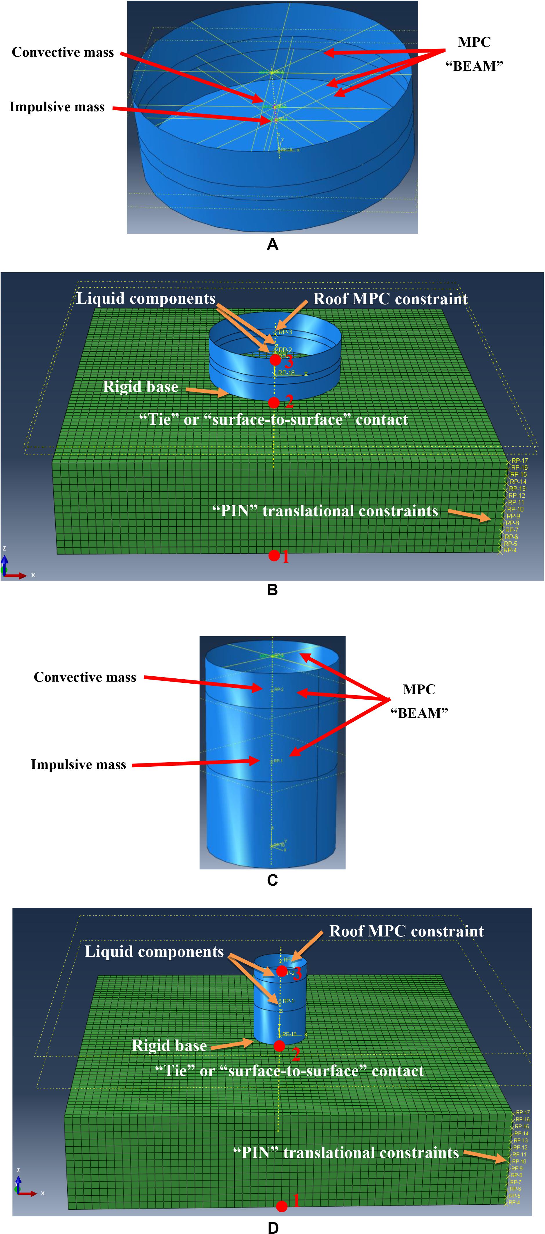
Figure 1. Simplified tank and coupled soil-superstructure models for the squat (A,B) and the slender tank (C,D).
Additionally, the impulsive (mi) and convective (mc) masses are connected with a vertical linear spring with stiffness, kc. The location (height) and the value of each mass, as well as the spring stiffness are calculated according to the recommendations of Eurocode 8 – Part 4 (CEN, 2006). Moreover, the hydrostatic pressures are imposed to the tank model as an initial pressure loading at the static step. The tank base is considered rigid because of the presence of the concrete foundation slab, whereas a diaphragm constraint is assigned to the upper tank wall nodes to simulate the tank roof (Bakalis et al., 2017). This approach is realistic when roof is considered as fixed and/or stiffeners have been installed at the top of the tank. According to Malhotra and Veletsos (1994), using the assumption of fixed-roof is valid, because the flexibility of the supporting structure of the roof shell does not affect much the response of tank.
The validation of the examined tank models has been performed via their modal analysis results. In particular, the fundamental period of each model was compared to the analytic impulsive eigenperiod of Eurocode 8 – Part 4 (CEN, 2006). Several relevant studies have proven that the total dynamic response of liquid-storage tanks is dominated by the impulsive liquid component (Veletsos et al., 1992; Malhotra, 1997). The properties of the examined storage tanks have been taken from the previous study of Haroun (1983) for broad and tall tanks. More details regarding the dimensions and properties of the models can be found in authors’ previous studies (Tsipianitis and Tsompanakis, 2018, 2019). The damping of the structural system has been set equal to 5% for the ultimate limit state (CEN, 2006) and 2 and 0.5% for the impulsive and convective liquid components, respectively.
The elastic modulus of steel material is E = 210 GPa, Poisson ratio is ν = 0.3, and steel material S235 is used (the yield stress is equal to 235 MPa). The impulsive period of the squat and slender tank is equal to 0.16 and 0.18 s, respectively, whereas the period of the convective liquid component is 6.89 and 4 s, respectively. It should be mentioned that the effect of filling percentage (FP) on the seismic response of liquid-storage tanks is investigated. For this reason, fully filled and partially filled tank models with 100 and 50% FP, respectively, are examined. Regarding the partially filled tanks, the impulsive periods of the squat and slender tank present lower values compared to the full tanks, i.e., 0.10 and 0.08 s, respectively. In contrast, the convective periods are increased for both tanks to 8.69 and 4.8 s, respectively.
Soil Layer Model
As it has been mentioned, the main purpose of the current study is to investigate the impact of DSSI on liquid-storage tanks, which requires the presence of a compliant foundation layer, as these phenomena are marginal in the case of stiff soil or rock. For this reason, the emphasis of the parametric investigation is given on the soft-soil case, and thus, the imposed seismic excitations have been chosen to be compatible with such geotechnical conditions (see section “Selection of Seismic Excitations for details”). Nonetheless, for comparison purposes, all analyses have also been performed without any interaction phenomena. More specifically, the second set of analyses refers to a very stiff foundation layer, i.e., the tanks were considered to be founded on Soil Class A (i.e., rock) according to Eurocode 8 (CEN, 2004a) using the same records.
Continuum 3D elements (C3D8R) are used for the realistic simulation of the elastic foundation layer, in contrast to the simplified approach that has been adopted for the modeling of liquid-storage tanks. As aforementioned, a parametric investigation is performed for a soft-soil layer with approximately Vs = 200 m/s, which corresponds to Soil Class C according to Eurocode 8. The density of the soil material is ρ = 1,850 kg/m3, elastic modulus is E = 207.2 MPa, and Poisson ratio is ν = 0.4. On the other hand, the density of the rock material is ρ = 2,500 kg/m3, elastic modulus is E = 20,720 MPa, and Poisson ratio is ν = 0.2 (resulting in Vs≈1840 m/s). The damping is set equal to 5% for both materials.
The height (Hs) of the soil layer is equal to 25 m, which corresponds to a fundamental period equal to: T = 4H/Vs = 0.5 s. According to the recommendations of Ghosh and Wilson (1969) and Sextos et al. (2017), the length (Ls) of soil model at two translational directions is considered as three times the diameter (D = 2R) of each tank, whereas the global mesh size is 2 m (Figure 2A). The horizontal seismic excitations are imposed at the base nodes of the soil model, whereas the vertical degree of freedom is not constrained at the lateral boundaries. Moreover, at each level along the height of the model “PIN” MPC constraints are assigned to the external lateral nodes to prevent from the lateral spread of the soil mass (Sextos et al., 2017). These MPC constraints provide a pinned joint between two nodes, whereas rotations are independent of each other (Dassault Systemes, 2016).
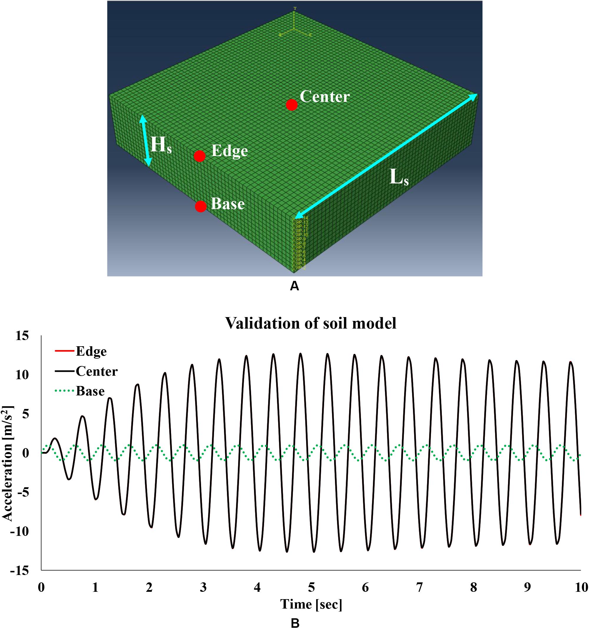
Figure 2. (A) Validation model of soil layer dynamic response and (B) imposed harmonic excitation at the base and computed accelerations at the center and the edge of soil surface.
The validation of the numerical model of the underlying soil (without the presence of tank) was performed in two parts: (a) achievement of the analytical amplification factor and (b) adequacy of the non-reflective lateral boundaries. First, a harmonic excitation with fundamental period equal to 0.5 s was imposed to the base nodes of the examined soil model. The validation is illustrated in Figure 2B, where the obtained maximum amplification factor (AF) of the accelerations is verified with the corresponding analytical value, which is equal to AF = 2/πξ≅ 12.7 at the surface of the soil layer (Figure 2A). In addition, the comparison of the responses at the center and the edge of the surface is depicted. It is evident that the numerical solution in both points is identical to the analytical solution; thus, no reflections of the seismic waves occur at the boundaries of the soil domain. Consequently, the modeling assumptions regarding the dimensions, mesh size, and boundaries of the soil domain are realistic and accurate.
Coupled Model
In previous investigations (e.g., Veletsos and Tang, 1990; Veletsos et al., 1992; Meng et al., 2019), analyses were performed using two-dimensional models to represent the soil–liquid–tank interaction. In addition, these studies adopted simplified approaches for both the liquid–tank and soil–structure interactions (using springs and dashpots). Lastly, only linear analyses were performed for both soil and storage tank materials.
In the present study, a coupled soil–tank model is developed in ABAQUS software to investigate the DSSI phenomena for two tank slenderness ratios (i.e., squat and slender tanks). In addition, suitable contact formulations are required to determine whether the tanks are either anchored or unanchored to their base. For this reason, “TIE constraint” is applied when the tanks are anchored, whereas “surface-to-surface” contact formulation with friction coefficient (μ1) equal to 0.4 (API, 2007) and (μ2) equal to 0.7 (Sextos et al., 2017) is assigned when the tanks are unanchored. The coupled model is validated using the analytical equation of Veletsos and Meek (1974) that calculates the fundamental period of the combined soil–tank system:
where T is the fundamental period of the tank [sec], k is the horizontal stiffness of the tank [N/m], ku is the horizontal stiffness of the circular base [N/m], kθ is the rocking stiffness of the circular base [N/m], and h is the tank height [m]. Subsequently, the analytical solution for the squat tank (Figure 1B) is equal to 0.37 s, while the modal period from ABAQUS is 0.38 s. Regarding slender tank (Figure 1D), the derived result from the numerical calculations is 0.76 s, while the analytical fundamental period is equal to 0.79 s. To validate the interaction effects of the proposed coupled models, the inequality that determines the foundation compliance in terms of inertial interaction must not be satisfied (Veletsos, 1977):
where h is the height of the structure [m], Vs is the shear wave velocity of the foundation soil [m/s], T refers to the fixed-base period of the structure [s], and r is the radius of the foundation mat [m]. In the examined cases, the result of the left part of this inequality is 0.34 and 0.80 for the squat and slender tank, respectively. Consequently, for both soil–tank models, the interaction effects can be investigated as the inequality is not satisfied.
In addition, both squat and slender soil–tank models are capable of capturing the height-wise stress distribution quite accurately. For instance, Figure 3 presents two characteristic screenshots, which show that the numerical model is capable of obtaining the stress concentration zones close to the bottom of the tank, which can lead to local buckling phenomena (e.g., “elephant foot” failure) for both squat and slender tanks.
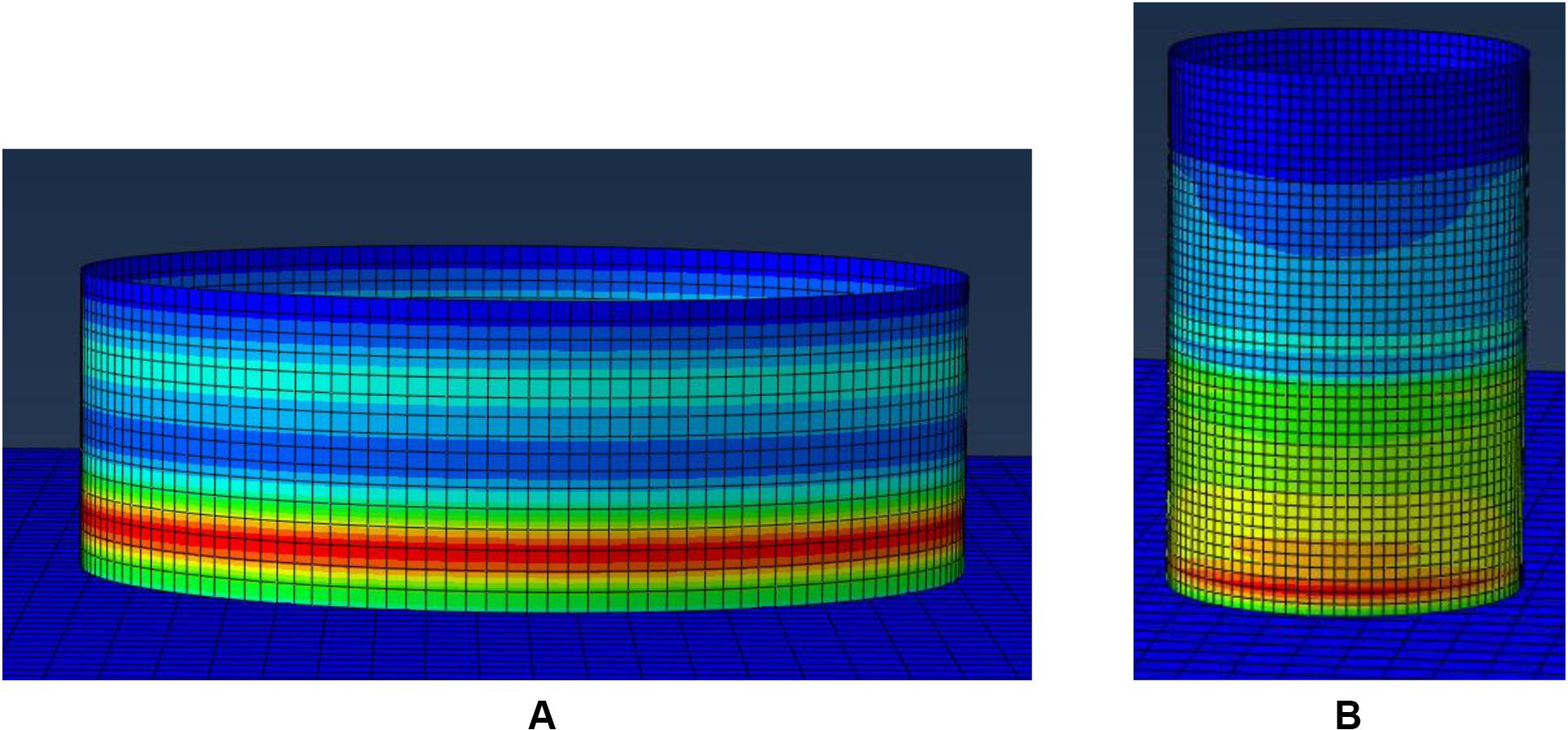
Figure 3. Illustrative height-wise distribution of von Mises stresses for (A) the squat tank and (B) the slender tank.
Selection of Seismic Excitations
For each slenderness ratio, different ground motion scaling was calculated according to the dynamic properties of tank models. More specifically, 10 earthquake records for soil type C were selected from PEER-NGA1 database, suitably scaled so that the value of spectral acceleration for the fundamental impulsive period of each tank (for fixed-base conditions) with damping is equal to 5% -[SA(T1,5%)]- equal to 0.36 g (Table 1), according to the elastic response spectrum of Eurocode 8 with γi = 1.6 (CEN, 2006).
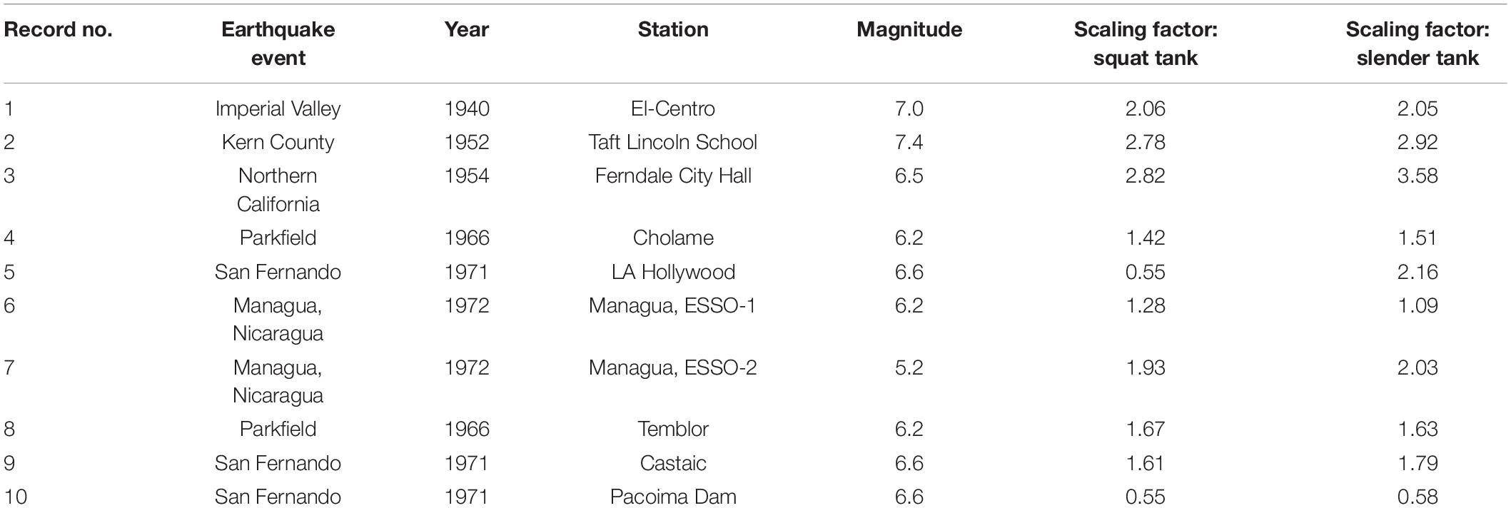
Table 1. Seismic records from PEER-NGA database.
As aforementioned in section “Simplified Tank Model,” the impulsive period is selected because several relevant studies have proven that the dynamic response of liquid-storage tanks is dominated by the impulsive liquid component, which has also been confirmed by the derived results. The scaled elastic spectra of the imposed ground motions for squat and slender tanks are provided in Figures 4A,B. As aforementioned, ABAQUS software is used to perform a series of non-linear dynamic analyses. For a more realistic representation of the results, geometrical (NLgeom: ON) and material (i.e., tank wall) non-linearities are considered.
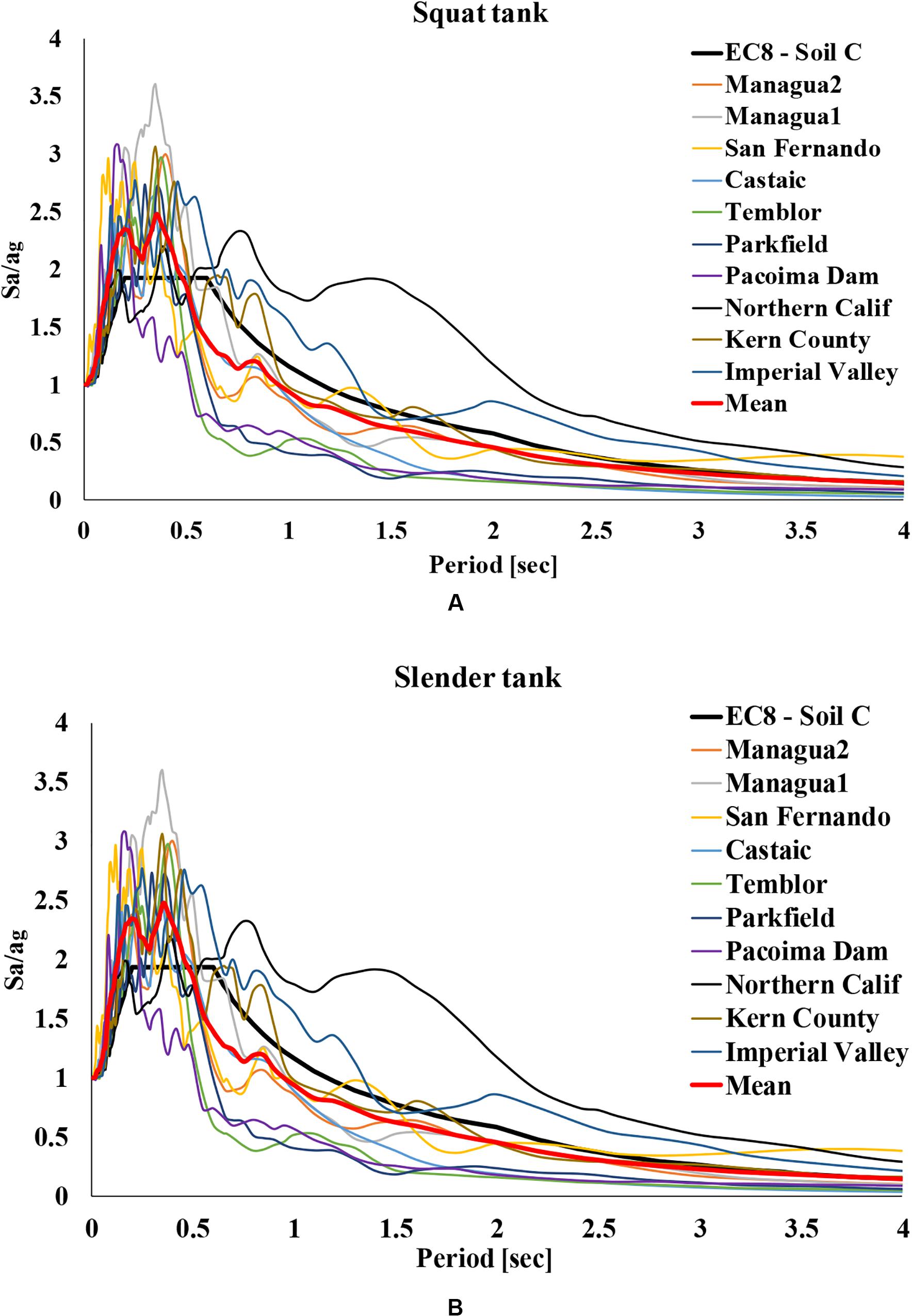
Figure 4. Scaled response spectra for (A) the squat and (B) the slender tank.
Numerical Results
In this section, the amplification or deamplification of the transmitted accelerations along the height of the coupled soil–tank model is investigated, in particular, the results at three characteristic points of the anchored (AN) and unanchored (UN) full tank models (Figures 1B,D) with μ1 = 0.4, as illustrated in Figures 5A–D for both tanks in terms of acceleration levels. More specifically, the first point (Location 1) refers to the foundation base, where the seismic excitations are imposed. The second point (Location 2) is located at the base of the tank, and the third point (Location 3) is at the top of the tank, where the diaphragm constraint has been assigned. In general, the amplification factor is defined as the ratio between the maximum absolute accelerations at the top and the base of a model. Hence, the amplification factor AF1 is related to the impact of the soil layer on the imposed excitation, as it represents the ratio of the maximum accelerations solely at the foundation layer. Amplification factor AF2 refers to the ratio of the maximum acceleration between the tank base and roof, whereas AF3 represents the maximum acceleration between the soil base and tank roof and represents the total amplification of the coupled soil–tank system.
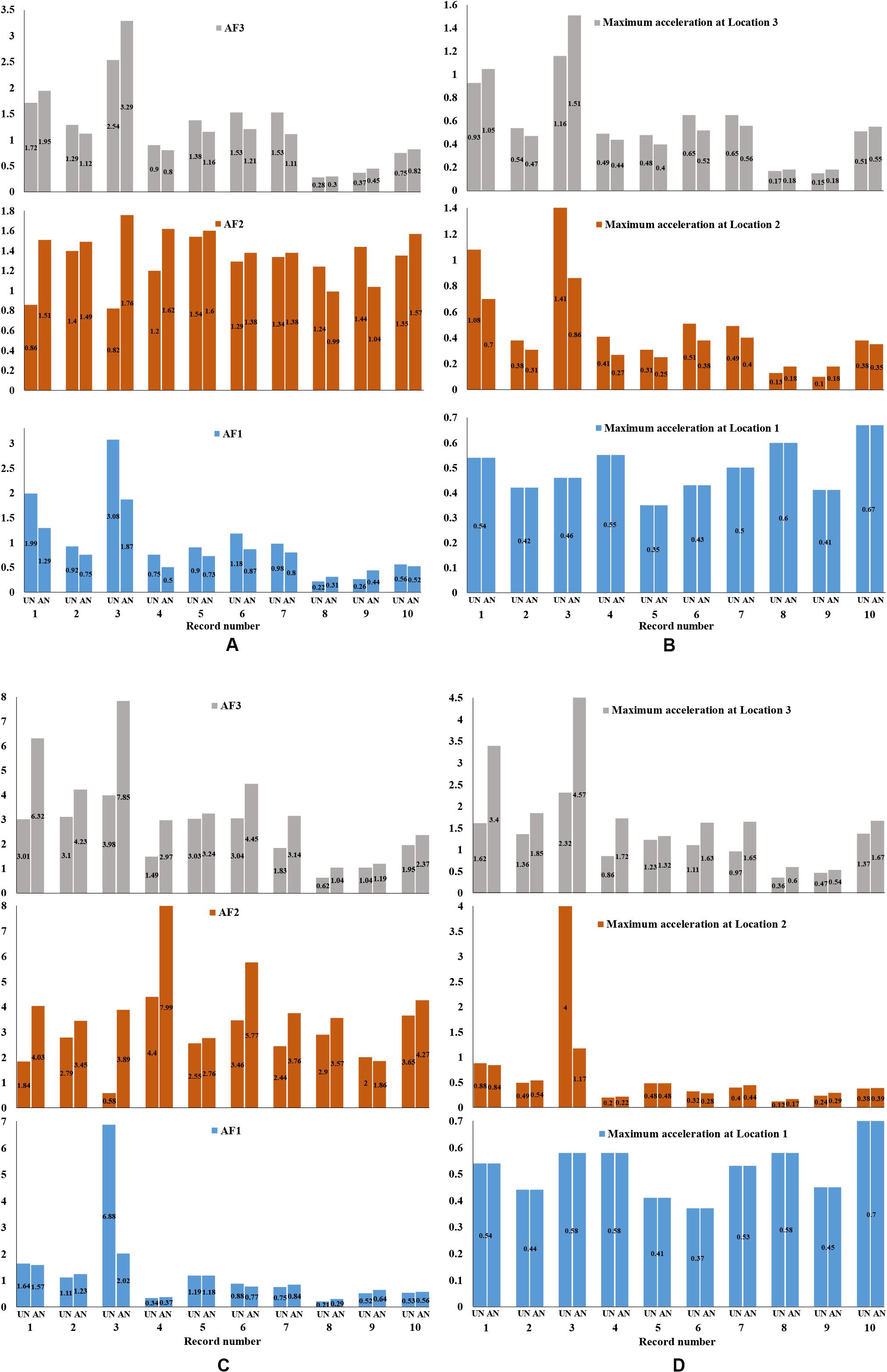
Figure 5. Comparison of the amplification factors (A) and maximum accelerations (B) for the squat and amplification factors (C) and maximum accelerations (D) for the slender tank, for anchored (AN) and unanchored (UN) conditions (with friction coefficient μ1 = 0.4).
As it is presented in Figures 5A,B, the acceleration results are widespread. Specifically, both amplifications and deamplifications are observed in the transmitted acceleration levels (in absolute values in all relevant plots). The maximum total amplification is observed for the Northern California record for the anchored tank with value equal to 3.29. In addition, the maximum deamplification is noticed for Parkfield–Temblor accelerogram for the unanchored tank with value equal to 0.28. The results obtained for the slender tank (Figures 5C,D) presented different behavior. In particular, in the majority of the examined cases and, especially, with respect to the total amplification factor (AF3), the seismic motion was significantly amplified.
Moreover, anchored tanks presented higher amplifications compared to the unanchored models. The highest total amplification is observed for Northern California excitation with value equal to 7.85, whereas the highest deamplification occurred for Parkfield–Temblor record with value equal to 0.62. A remarkable amplification factor regarding only the soil layer response is observed for the Northern California record (AF1 is equal to 6.88), whereas the tank behaves quite differently as deamplification is observed (AF2 is 0.58). In contrast, by checking solely the tank, the highest amplification AF2 is noticed for the Parkfield–Cholame record (equal to 7.99), whereas the soil layer deamplifies the specific excitation (AF1 is only 0.37).
Impact of Friction Coefficient
In this section, two different values taken from the literature, namely, 0.4 and 0.7, for the friction coefficient between the tank base and soil foundation are examined. The amplification factors along model height – as well as base sliding and uplifting phenomena in a subsequent section – for each friction coefficient value are examined. More specifically, Figures 6A,B present the acceleration response results and the amplification factors for the two examined friction coefficients regarding the unanchored squat tank. It can be observed that, in the majority of the examined cases, slightly increased accelerations are derived for friction coefficient equal to 0.4.
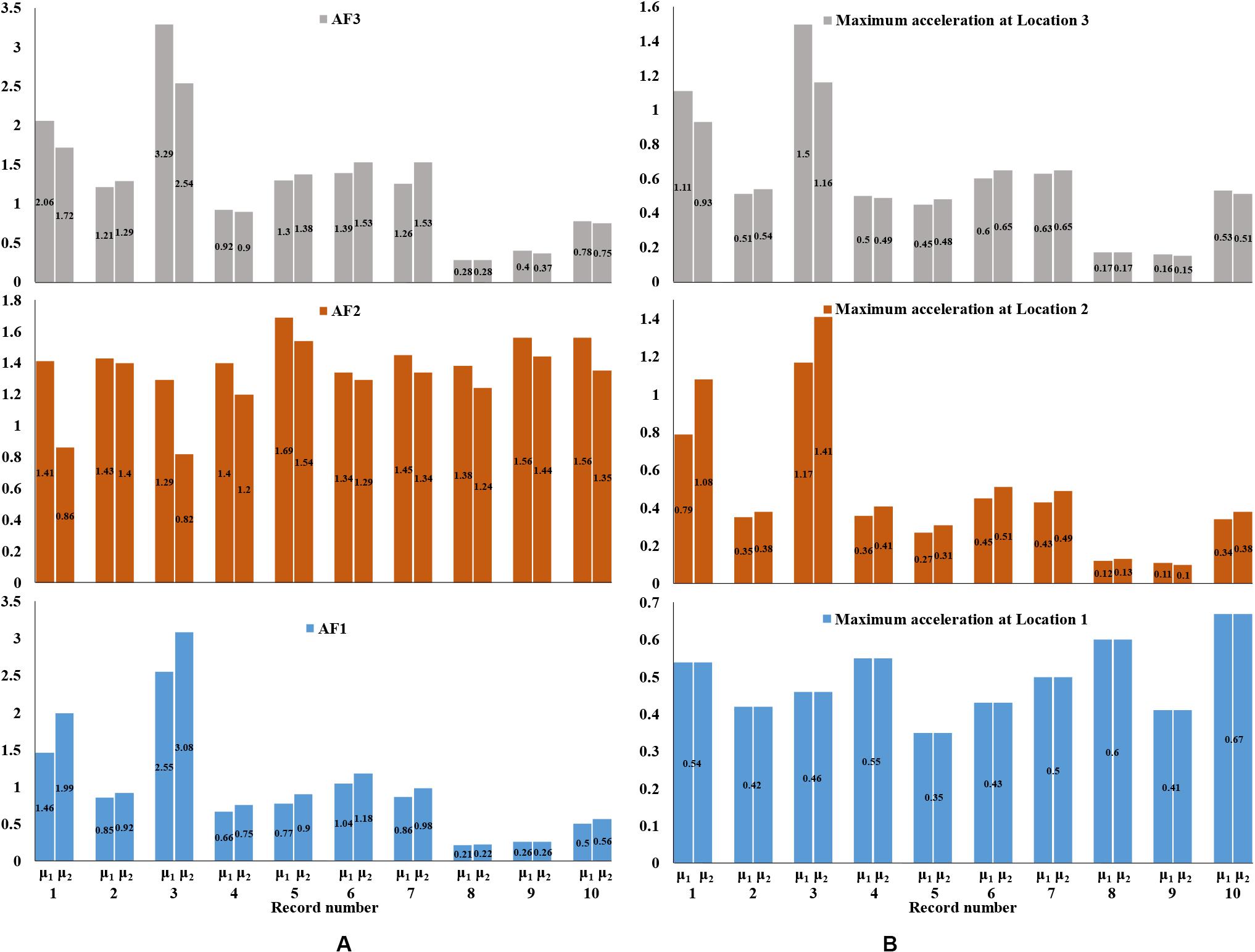
Figure 6. Comparison of the amplification factors (A) and maximum accelerations (B) for the unanchored squat tank for two friction coefficients (μ1 = 0.4 and μ2 = 0.7).
Impact of Liquid Content
Following the same methodology regarding the amplification or deamplification of the accelerations along the height of the model, the effect of FP of the tank (i.e., the percentage of the liquid content) is presented in this section. Specifically, two cases of FP are investigated for each tank slenderness ratio and for each fixity type: fully filled tank (100% FP) and partially filled tank (50% FP). In accordance with the descriptions in section “Simplified Tank Model,” Table 2 summarizes the main parameters for both tank models with 50 and 100% FP of liquid content.
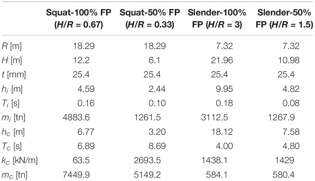
Table 2. Model parameters for the squat and the slender tank with 50 and 100% FP.
The results for the squat tank shown in Figures 7A,B do not present significant differences with respect to the liquid volume in the tank. More specifically, the amplification factors present deamplification and slight amplification for 50 and 100% FP, anchored and unanchored storage tanks. The highest amplification for the fully filled anchored tank is observed for the Northern California record with AF3 value equal to 3.29, whereas for the same record AF3 is equal to 2.44 for the partially filled tank. In contrast, the highest deamplification for the fully filled unanchored tank is where AF3 is equal to 0.28 for the Parkfield–Temblor record, whereas for the partially filled tank, AF3 is equal to 0.37 for this ground motion.
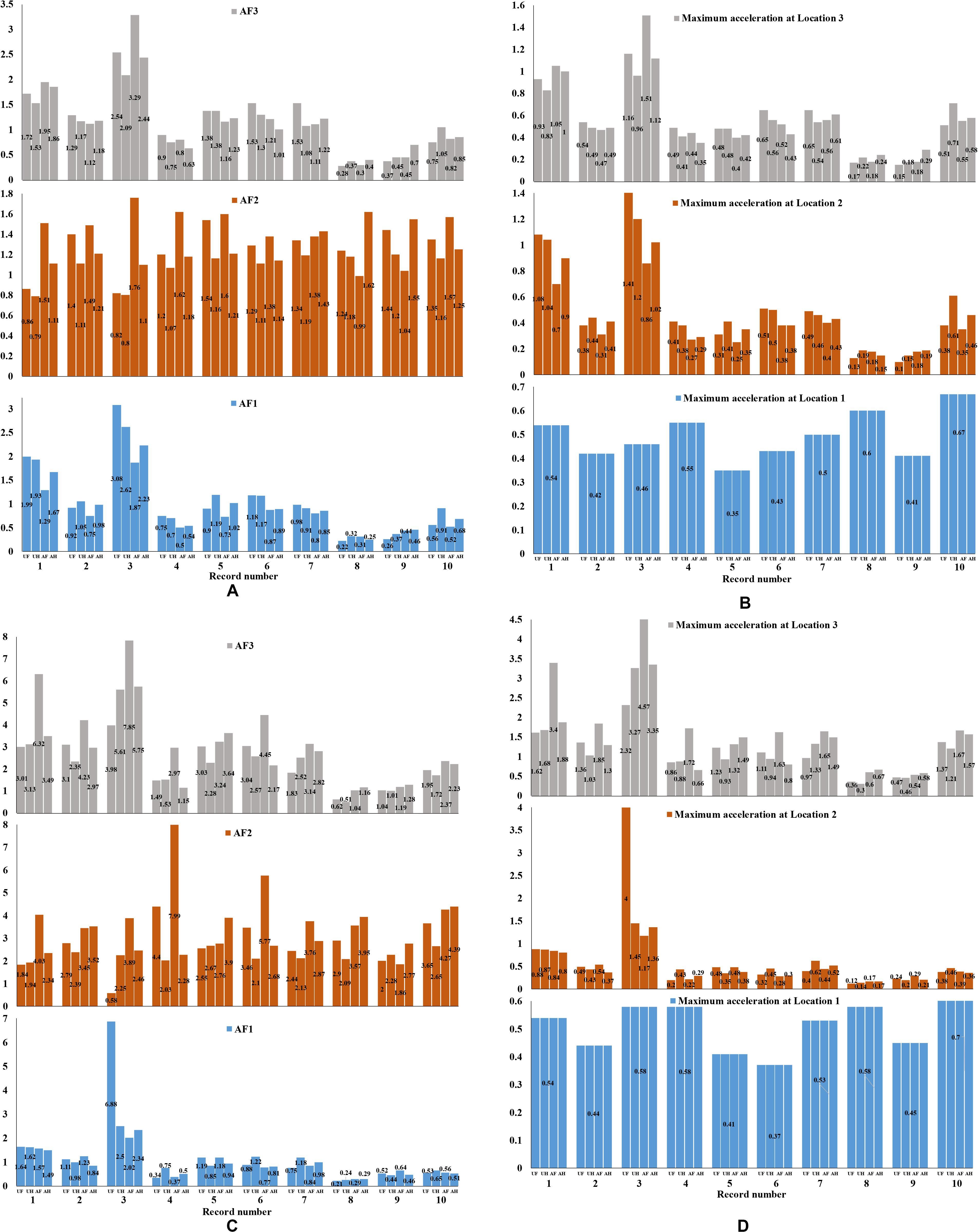
Figure 7. Comparison of the amplification factors (A) and maximum accelerations (B) for the squat and amplification factors (C) and maximum accelerations (D) for the slender tank, for anchored and unanchored conditions (with friction coefficient μ1 = 0.4) for full-filled (UF and AF) and half-filled (UH and AH) cases.
Regarding the slender tank, as presented in Figures 7C,D, the partially filled tank presented lower acceleration values than the fully filled tank in most cases. The highest amplification AF3 for 100% filled anchored tank is computed for Northern California record (AF3 = 7.85). Additionally, the highest deamplification is calculated for Parkfield–Temblor record, because AF3 is equal to 0.62 and 0.51 for the 100 and 50% filled unanchored tank, respectively.
Impact of Foundation Layer
In this section, the impact of the foundation stiffness on the seismic response of the examined storage tanks is presented. The properties for the soft soil and rock materials have been described in section “Soil Layer Model.” Indicative results regarding the seismic performance of unanchored (μ1 = 0.4) squat and slender tanks founded on soft soil or rock are presented. In particular, Figures 8A–D depict the acceleration results for the squat and the slender tank. Quite widespread results have been obtained, depending on the special frequency content of each ground motion imposed to the soil–structure system, as it has been also reported by Kianoush and Ghaemmaghami (2011) for rectangular tanks.
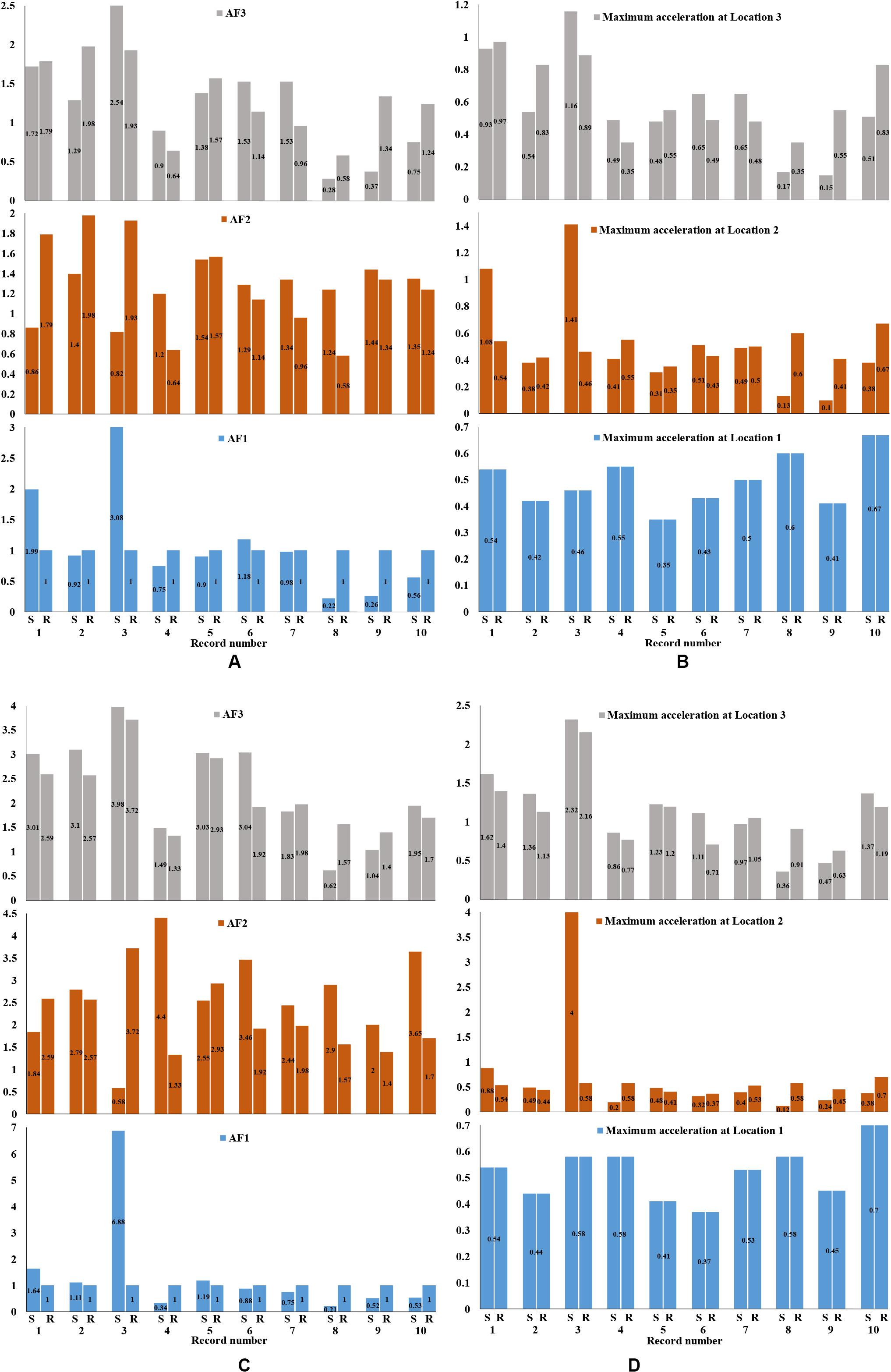
Figure 8. Comparison of the amplification factors (A) and maximum accelerations (B) for the squat and amplification factors (C) and maximum accelerations (D) for the slender tank, for foundation on soft soil (S) and rock (R) for the unanchored cases (with friction coefficient μ1 = 0.4).
Regarding the squat tank (see Figures 8A,B), the amplification factor AF3 presents its maximum value (equal to 2.54) for the Northern California record for soft soil, whereas the maximum deamplification is equal to 0.28 for the soft soil and Parkfield–Temblor record. The maximum amplification factor (equal to 3.98) for the slender tank (see Figures 8C,D) is computed for the Northern California record for soft soil. In addition, the maximum deamplification, i.e., AF3, is equal to 0.62, for the soft soil and Parkfield–Temblor record.
Base Sliding and Base Uplifting
Base sliding and base uplifting phenomena can cause severe damages to the tanks, especially during strong seismic events. Buckling of the tank wall, excessive sloshing, detachment of the pipe connections, and tank rocking consist the main failure types that have been observed in past earthquakes due to sliding and uplifting. Consequently, it is mandatory to perform an elaborate study regarding these phenomena to ensure the structural integrity of these important structures under severe earthquakes.
First, the base sliding results are compared for each tank slenderness ratio, while the impact of liquid FP on tank deformations is also examined. Figure 9A depicts the base sliding results for the 100% FP squat and slender tanks. It is obvious that in many records and especially record no. 5 (Northern California), the slender tank exhibits higher relative displacements, which is in accordance with the conclusions of Kalemi et al. (2019). The results for 50% FP are illustrated in Figure 9B, where there is a significant difference for Northern California record, whereas in the majority of the other ground motions, the slender tank presents the highest values. It can be easily noticed that the 50% FP slender tank exhibits the maximum base sliding value.
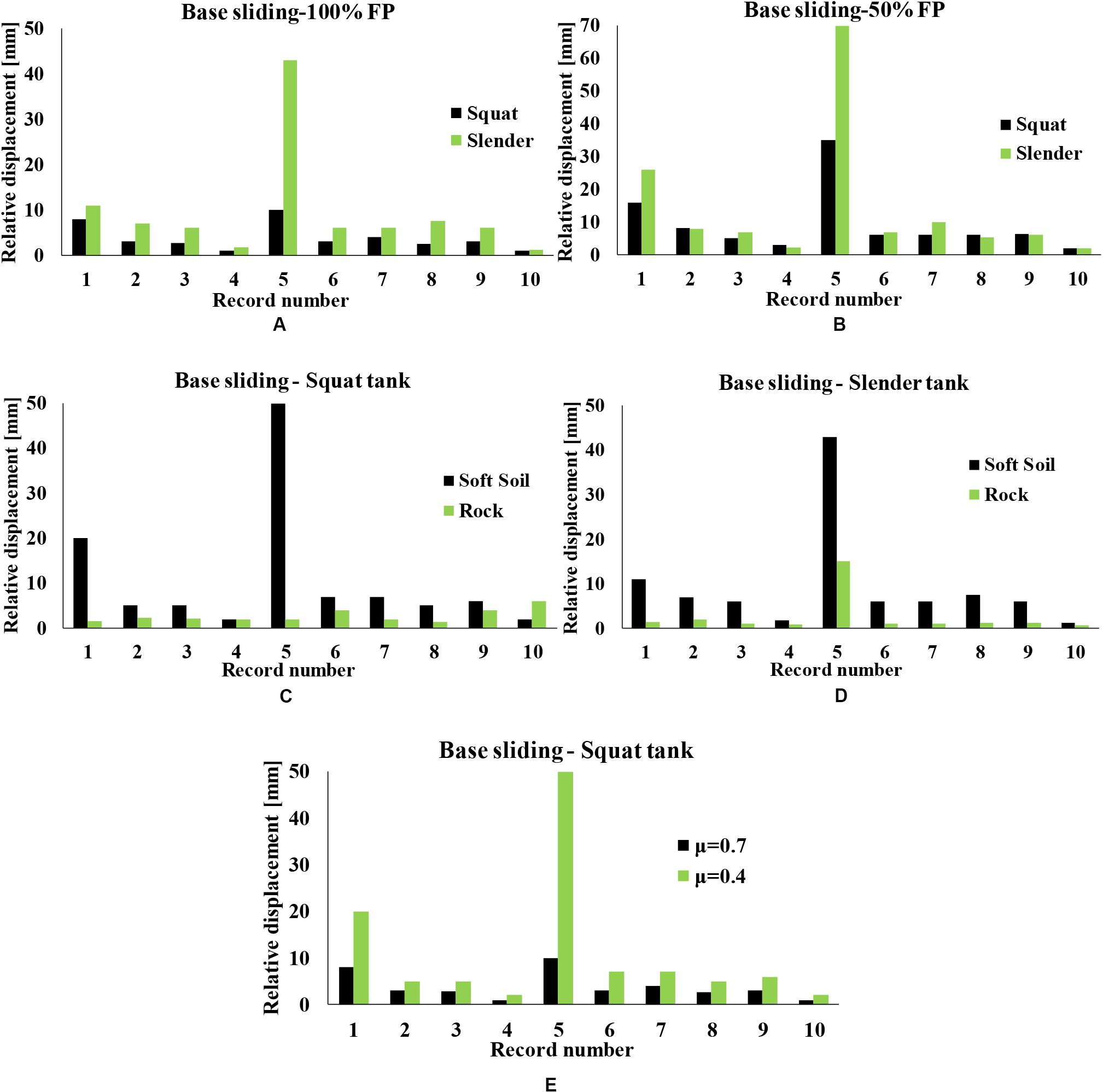
Figure 9. Base sliding results of (A) 100% FP and (B) 50% squat and slender tank, (C) squat and (D) slender tank for different foundation layer types, and (E) comparison of friction coefficient for the unanchored squat tank.
Figure 10A presents the uplifting results for the 100% FP squat and slender tanks. In this case, it is more evident that the slender tank exhibits higher relative displacements compared to the squat tank. In addition, Figure 10B depicts the base uplifting for the 50% FP tank, in which a greater variation of results is observed. The volume of the liquid (FP) had a significant impact on the sliding and uplifting results, as it has been also reported by Phan et al. (2019). Similarly, the fully filled tanks present higher uplifting displacements compared to the half-filled tank cases. The effect of soil type on the presence of base sliding and uplifting phenomena for the squat and the slender tanks is depicted in Figures 9C,D and Figures 10C,D. It is evident that base sliding for both tank geometries is more pronounced when the tank is founded on soft soil, which is in accordance with the experimental findings of Ormeño et al. (2019). Regarding the base uplifting, the results lead to similar conclusions, i.e., soft soil results in higher base uplifting displacements compared to the foundation on rock.
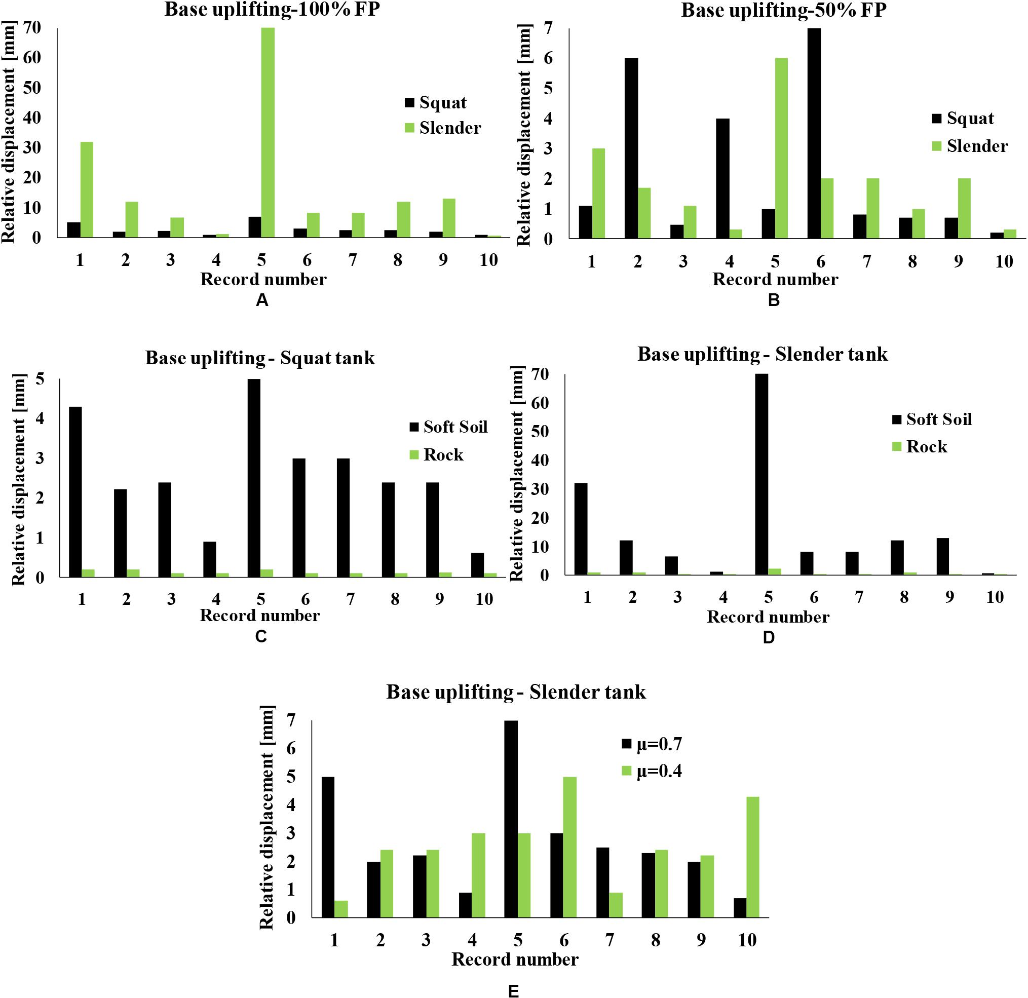
Figure 10. Base uplifting results of (A) 100% FP and (B) 50% squat and slender tank, (C) squat and (D) slender tank for different foundation layer types, and (E) comparison of friction coefficient for the unanchored slender tank.
Figure 9E illustrates the sliding results for the squat tank, which are more susceptible to such phenomena, for different friction coefficient values, namely, 0.4 and 0.7. In addition, Figure 10E displays the uplifting results for the slender tank, which is more vulnerable compared to the broad tank, to such distress. As expected, in the majority of cases, μ1 = 0.4 leads to higher values of sliding and uplifting displacements compared to μ2 = 0.7.
It should be mentioned that, in all cases, extreme values are observed for the examined parameters when imposing the Northern California record. For this reason, the time-histories of relative displacements for this record for the anchored and the unanchored squat tank (μ1 = 0.4) and soft soil conditions are shown in Figure 11A for base uplifting and in Figure 11B for base sliding. It can be noticed that the slender tank presents significantly higher values compared to squat tank. These results are in accordance with the findings of Malhotra and Veletsos (1994) and CEN (2006), where it is reported that uplifting phenomena are more pronounced in slender tanks. The base sliding time-histories in Figure 11B show that the squat tank exhibits slightly higher sliding than the slender tank.
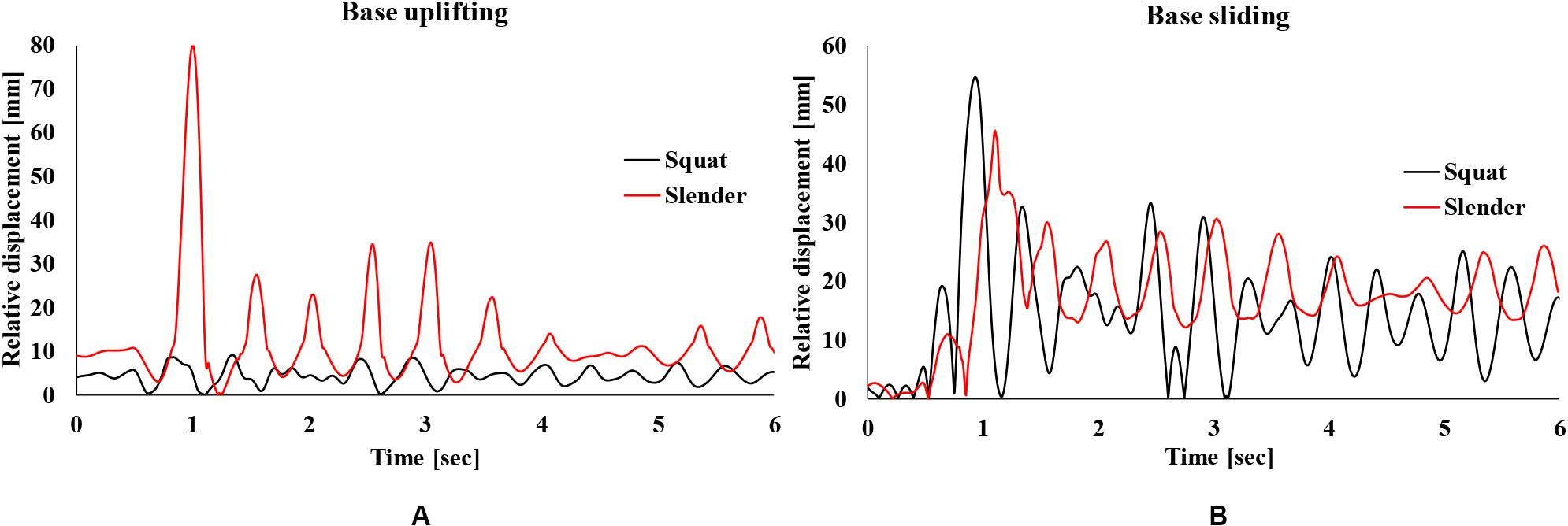
Figure 11. Relative displacement time-histories for the Northern California record for the unanchored (μ1 = 0.4) squat and slender tanks for soft soil conditions: base uplifting (A) and base sliding (B).
The special frequency content of this ground motion, in which a very large pulse occurs at the beginning of the excitation, leads also to high amplification of the accelerations, as highlighted in the time-histories of Figure 12 for the unanchored squat tank for soft soil conditions and μ1 = 0.4. This is further illustrated in Figure 13, which displays the base shear time-histories (impulsive Figure 13A and convective Figure 13B components) at X direction for the anchored and the unanchored squat tank (μ1 = 0.4) and soft soil conditions. As it can be easily observed, the impulsive base shear presents much higher values than convective base shear, which verifies the dominance of the impulsive liquid component in seismic response of the tanks. In addition, the unanchored slender tank exhibits the highest impulsive base shear values (due to higher acceleration levels, as presented in Figure 5), whereas the highest convective base shear values are observed in the anchored slender tank. The latter is in accordance with relevant studies (e.g., Malhotra et al., 2000) in the literature, which also conclude that the role of the impulsive component of the liquid content is more pronounced in slender tanks compared to squat tanks.
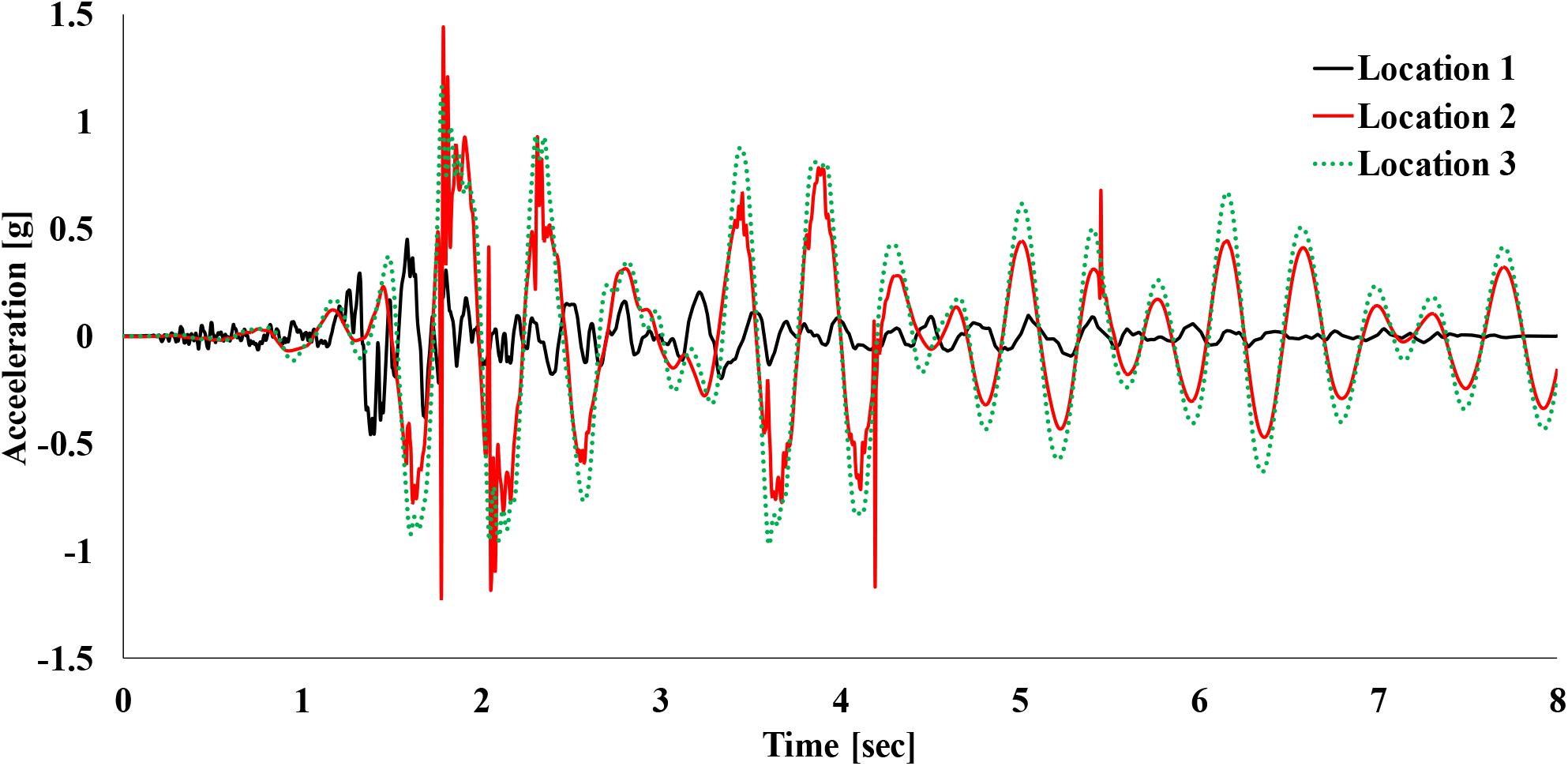
Figure 12. Acceleration time-histories at the three points of interest (see Figure 1B) for the Northern California record for the unanchored (μ1 = 0.4) squat tank for soft soil conditions.
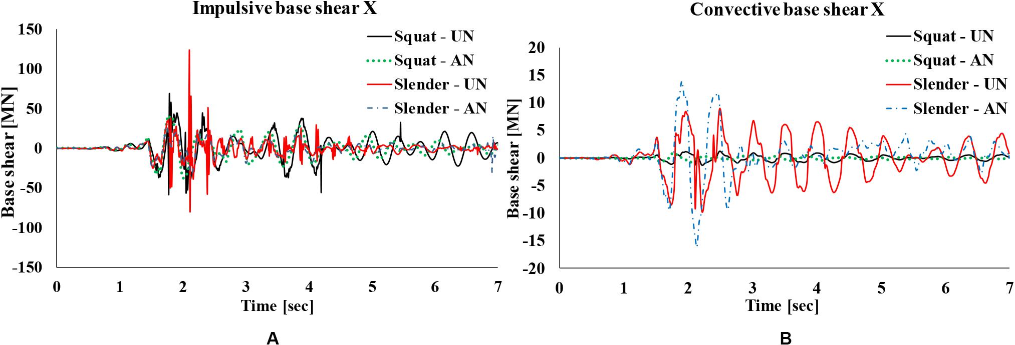
Figure 13. Base shear at X direction for the Northern California record for the anchored and the unanchored (μ1 = 0.4) squat tank for soft soil conditions: impulsive (A) and convective (B) components.
Conclusions
In the current article, the impact of the DSSI on the seismic response of liquid-storage tanks was investigated. For this purpose, utilizing FEM, an efficient coupled soil–tank model has been developed to examine this complex phenomenon. After the validation of the numerical modeling approach, parametric non-linear dynamic analyses have been performed using 10 records from PEER-NGA database for two tank geometries (squat and slender), two foundation layer types (soft soil and rock), two cases of liquid content (half and full-filled tank), and two fixity conditions (anchored and unanchored). The presented results have been focused on the amplification or deamplification of the imposed accelerations, as well as base sliding and base uplifting phenomena.
It has been shown that the simplified spring-mass model can effectively simulate the seismic behavior of anchored and unanchored liquid-storage tanks. The main conclusions that can be derived from the present investigation are the following:
(a) The anchored slender tank presented the highest acceleration amplifications.
(b) The impact of liquid content volume is more significant for the slender tank, in which lower accelerations were presented compared to the squat tank for both 50 and 100% FP.
(c) A smaller friction coefficient value (μ1 = 0.4) leads to increased accelerations compared to a larger value (μ2 = 0.7). Friction coefficient value strongly influences base sliding results.
(d) The slender tank is more vulnerable to uplifting and sliding, while the liquid volume has a considerable effect on such phenomena. The presence of a soft soil layer contributes to the increase of sliding and uplifting for both tank geometries.
Undoubtedly, further investigation of this complex phenomenon is required, including a more detailed modeling of the liquid content in order to assess potential damages due to sloshing as well as local buckling phenomena, such as “elephant-foot” and “diamond-shape.” For instance, the effect of the second convective (sloshing) mode (Kalogerakou et al., 2017) on the seismic response of soil-supported tanks, especially under near-fault excitations, should be examined. Furthermore, the impact of base-isolation systems, which are often used to protect large-scale liquid-storage tanks, on the seismic response of liquid-storage tanks founded on soft soils should also be investigated, which is currently under development.
Data Availability Statement
The datasets generated for this study are available on request to the corresponding author.
Author Contributions
YT supervised the study and guided AT to carry out the literature review and to perform the required runs for the dynamic analyses. PP assisted AT to develop the numerical models. All authors analyzed and interpreted the results and contributed to the completion of the manuscript.
Funding
This research has been generously supported by Dr. Emmanouil Michailakis via a Ph.D. scholarship for AT, which is gratefully acknowledged.
Conflict of Interest
The authors declare that the research was conducted in the absence of any commercial or financial relationships that could be construed as a potential conflict of interest.
Footnotes
References
Anand, V., and Kumar, S. R. S. (2018). Seismic soil-structure interaction: a state-of-the-art review. Structures 16, 317–326. doi: 10.1016/j.istruc.2018.10.009
API (2007). API 650 Welded Tanks for Oil Storage, 11th Edn. Washington, DC: American Petroleum Institute.
Bakalis, K., Fragiadakis, M., and Vamvatsikos, D. (2017). Surrogate modeling for the seismic performance assessment of liquid storage tanks. J. Struct. Eng. 143, 1–13. doi: 10.1061/(ASCE)ST.1943-541X.0001667
Buratti, N., and Tavano, M. (2013). Dynamic buckling and seismic fragility of anchored steel tanks by the added mass method. Earthquake Eng. Struct. Dyn. 43, 1–21. doi: 10.1002/eqe.2326
CEN (2004a). Eurocode 8: Design of Structures for Earthquake Resistance - Part 1: General Rules, Seismic Actions and Rules for Buildings. Brussels: European Committee for Standardization.
CEN (2004b). Eurocode 8: Design of Structures for Earthquake Resistance - Part 5: Foundations, Retaining Structures and Geotechnical Aspects. Brussels: European Committee for Standardization.
CEN (2006). Eurocode 8: Design of structures for Earthquake Resistance - Part 4: Silos, Tanks and Pipelines. Brussels: European Committee for Standardization.
Chatterjee, P., and Basu, B. (2001). Non-stationary seismic response of tanks with soil interaction by wavelets. Earthquake Eng. Struct. Dyn. 30, 1419–1437. doi: 10.1002/eqe.70
Dassault Systemes (2016). ABAQUS 6.14-5, Analysis User’s Guide. Vélizy-Villacoublay: Dassault Systemes.
De Angelis, M., Giannini, R., and Paolacci, F. (2010). Experimental investigation on the seismic response of a steel liquid storage tank equipped with floating rood by shaking table tests. Earthquake Eng. Struct. Dyn. 39, 377–396. doi: 10.1002/eqe.945
Erkmen, B. (2017). “Evaluation of code provisions for seismic performance of unanchored liquid storage tanks,” in Proceedings of the 6th ECCOMAS Thematic Conference on Computational Methods in Structural Dynamics and Earthquake Engineering (COMPDYN 2017), Rhodes island.
FEMA (2005). Improvement of Nonlinear Static Seismic Analysis Procedures. FEMA 440. Washington DC: Federal Emergency Management Agency.
Gazetas, G. (1991). “Foundation vibrations,” in Foundation Engineering Handbook, 2nd Edn, ed. H. Y. Fang (Cham: Kluwer/Springer), 553–593. doi: 10.1007/978-1-4615-3928-5_15
Ghosh, S., and Wilson, E. L. (1969). Dynamic Stress Analysis of Axisymmetric Structures Under Arbitrary Loading. Report No. EERC 69-10. Berkeley: University of California.
Halabian, A. M., and El Naggar, M. H. (2002). Effect of non-linear soil-structure interaction on seismic response of tall slender structures. Soil Dyn. Earthquake Eng. 22, 639–658. doi: 10.1016/S0267-7261(02)00061-1
Haroun, M. A. (1983). Vibration studies and tests of liquid storage tanks. Earthquake Eng. Struct. Dyn. 11, 179–206. doi: 10.1002/eqe.4290110204
Haroun, M. A., and Abou-Izzeddine, W. (1992a). Parametric study of seismic soil-tank interaction. I: horizontal excitation. J. Struct. Eng. 118, 783–797. doi: 10.1061/(ASCE)0733-94451992118:3(783)
Haroun, M. A., and Abou-Izzeddine, W. (1992b). Parametric study of seismic soil-tank interaction. II: vertical excitation. J. Struct. Eng. 118, 798–811. doi: 10.1061/(ASCE)0733-94451992118:3(798)
Kalemi, B., Farhan, M., and Corritore, D. (2019). “Sliding response of unanchored steel storage tanks subjected to seismic loading,” in Proceedings of the ASME 2019 Pressure Vessels & Piping Conference, San Antonio, TX.
Kalogerakou, M. E., Maniatakis, C. A., Spyrakos, C. C., and Psarropoulos, P. N. (2017). Seismic response of liquid-containing tanks with emphasis on the hydrodynamic distress and near-fault phenomena. Eng. Struct. 153, 383–403. doi: 10.1016/j.engstruct.2017.09.026
Kianoush, M. R., and Ghaemmaghami, A. R. (2011). The effect of earthquake frequency content on the seismic behavior of concrete rectangular liquid tanks using finite element method incorporating soil-structure interaction. Eng. Struct. 33, 2186–2200. doi: 10.1016/j.engstruct.2011.03.009
Kildashti, K., and Mirzadeh, N. (2015). “Seismic behavior of anchorage in diverse liquid storage steel tanks by added-mass method,” in Implementing Innovative Ideas in Structural Engineering and Project Management, eds S. Saha, Y. Zhang, S. Yazdani, and A. Singh (Fargo, ND: ISEC Press), 325–330.
Kim, J. M., Chang, S. H., and Yun, C. B. (2002). Fluid-structure-soil interaction analysis of cylindrical liquid storage tanks subjected to horizontal earthquake loading. Struct. Eng. Mech. 13, 615–638. doi: 10.12989/sem.2002.13.6.615
Konstandakopoulou, F. D., and Hatzigeorgiou, G. D. (2017). Water and wastewater steel tanks under multiple earthquakes. Soil Dyn. Earthquake Eng. 100, 445–453. doi: 10.1016/j.soildyn.2017.06.026
Larkin, T. (2008). Seismic response of liquid storage tanks incorporating soil structure interaction. J. Geotech. Geoenviron. Eng. 134, 1804–1814. doi: 10.1061/(ASCE)1090-02412008134:121804
Malhotra, P. K. (1997). Seismic response of soil-supported unanchored liquid-storage tanks. J. Struct. Eng. 123, 440–450. doi: 10.1061/(ASCE)0733-94451997123
Malhotra, P. K., and Veletsos, A. S. (1994). Uplifting response of unanchored liquid-storage tanks. J. Struct. Eng. 120, 3525–3547. doi: 10.1061/(ASCE)0733-94451994120
Malhotra, P. K., Wenk, T., and Wieland, M. (2000). Simple procedure for seismic analysis of liquid-storage tanks. Struct. Eng. Int. 10, 197–201. doi: 10.2749/101686600780481509
Meng, X., Li, X., Xu, X., Zhang, J., Zhou, W., and Zhou, D. (2019). Earthquake response of cylindrical storage tanks on an elastic soil. J. Vibrat. Eng. Technol. 7, 433–444. doi: 10.1007/s42417-019-00141-0
Mylonakis, G., and Gazetas, G. (2000). Seismic soil-structure interaction: beneficial or detrimental? J. Earthquake Eng. 4, 277–301. doi: 10.1080/13632460009350372
Ormeño, M., Larkin, T., and Chouw, N. (2019). Experimental study of the effect of a flexible base on the seismic response of a liquid storage tank. Thin Walled Struct. 139, 334–346. doi: 10.1016/j.tws.2019.03.013
Phan, H. N., and Paolacci, F. (2018). “Fluid-structure interaction problems: an application to anchored and unanchored steel storage tanks subjected to seismic loadings,” in Proceedings of the 16th European Conference on Earthquake Engineering, 18-21 June 2018, Thessaloniki.
Phan, H. N., Paolacci, F., and Alessandri, S. (2019). Enhanced seismic fragility analysis of unanchored steel storage tanks accounting for uncertain modeling parameters. J. Pressure Vessel Technol. Trans. ASME 141:010903. doi: 10.1115/1.4039635
Ruiz, D. P., and Gutiérrez, S. G. (2015). Finite element methodology for the evaluation of soil damping in LNG tanks supported on homogeneous elastic halfspace. Bull. Earthquake Eng. 13, 755–775. doi: 10.1007/s10518-014-9655-4
Sextos, A. G., Manolis, G. D., Athanasiou, A., and Ioannidis, N. (2017). Seismically induced uplift effects on nuclear power plants. Part 1: containment building rocking spectra. Nuclear Eng. Des. 318, 276–287. doi: 10.1016/j.nucengdes.2016.12.035
Shrimali, M. K., and Jangid, R. S. (2002). Seismic response of liquid storage tanks isolated by sliding bearings. Eng. Struct. 24, 909–921. doi: 10.1016/S0141-0296(02)00009-3
Shrimali, M. K., and Jangid, R. S. (2003). Seismic response of base-isolated liquid storage tanks. J. Vibrat. Control 9, 1201–1218. doi: 10.1177/107754603030612
Tsipianitis, A., and Tsompanakis, Y. (2018). Seismic vulnerability assessment of liquid storage tanks isolated by sliding-based systems. Adv. Civil Eng. 2018:5304245. doi: 10.1155/2018/5304245
Tsipianitis, A., and Tsompanakis, Y. (2019). Impact of damping modeling on the seismic response of base-isolated liquid storage tanks. Soil Dyn. Earthquake Eng. 121, 281–292. doi: 10.1016/j.soildyn.2019.03.013
Veletsos, A. S. (1977). “Dynamics of structure foundation systems,” in Structural and Geotechnical Mechanics, ed. N. W. Newmark (Upper Saddle River, NJ: Prentice Hall), 333–361.
Veletsos, A. S., and Meek, J. W. (1974). Dynamic behaviour of building-foundation systems. Earthquake Eng. Struct. Dyn. 3, 121–138. doi: 10.1002/eqe.4290030203
Veletsos, A. S., and Tang, Y. (1990). Soil-structure interaction effects for laterally excited liquid storage tanks. Earthquake Eng. Struct. Dyn. 19, 473–496. doi: 10.1002/eqe.4290190402
Veletsos, A. S., Tang, Y., and Tang, H. T. (1992). Dynamic response of flexibly supported liquid-storage tanks. J. Struct. Eng. 118, 264–283. doi: 10.1061/(ASCE)0733-94451992118:1(264)
Virella, J. C., Godoy, L. A., and Suarez, L. E. (2006a). Dynamic buckling of anchored steel tanks subjected to horizontal earthquake excitation. J. Constr. Steel Res. 62, 521–531. doi: 10.1016/j.jcsr.2005.10.001
Virella, J. C., Godoy, L. A., and Suarez, L. E. (2006b). Fundamental modes of tank-liquid systems under horizontal motions. Eng. Struct. 28, 1450–1461. doi: 10.1016/j.engstruct.2005.12.016
Virella, J. C., Suarez, L. E., and Godoy, L. A. (2005). Effect of pre-stress states on the impulsive modes of vibration of cylindrical tank-liquid systems under horizontal motions. J. Vibrat. Control 11, 1195–1220. doi: 10.1177/1077546305057221
Keywords: liquid-storage tanks, soil–structure interaction, friction, base sliding, base uplifting
Citation: Tsipianitis A, Tsompanakis Y and Psarropoulos PN (2020) Impact of Dynamic Soil–Structure Interaction on the Response of Liquid-Storage Tanks. Front. Built Environ. 6:140. doi: 10.3389/fbuil.2020.00140
Received: 12 February 2020; Accepted: 27 July 2020;
Published: 28 August 2020.
Edited by:
Vagelis Plevris, Oslo Metropolitan University, NorwayReviewed by:
Fabrizio Paolacci, Roma Tre University, ItalyHoang Nam Phan, Roma Tre University, Italy
Copyright © 2020 Tsipianitis, Tsompanakis and Psarropoulos. This is an open-access article distributed under the terms of the Creative Commons Attribution License (CC BY). The use, distribution or reproduction in other forums is permitted, provided the original author(s) and the copyright owner(s) are credited and that the original publication in this journal is cited, in accordance with accepted academic practice. No use, distribution or reproduction is permitted which does not comply with these terms.
*Correspondence: Yiannis Tsompanakis, anRAc2NpZW5jZS50dWMuZ3I=