 Yoichi Mukai
 Ayaka Yokoyama
 Kohiro Fushihara1
 Takashi Fujinaga
 Hideo Fujitani
- 1Department of Architecture, Graduate School of Engineering, Kobe University, Kobe, Japan
- 2Research Center for Urban Safety and Security, Kobe University, Kobe, Japan
The seismic responses of a single-story reinforced concrete (RC) frame building model under control using an active mass damper (AMD) are demonstrated through a real-time hybrid simulation (RTHS) method. In this study, the RTHS test is carried out by using a hydraulic actuator and a shaking table under synchronization. Most parts of the target RC frame model are provided as an analytical model for an online computer simulation, and only the single column of the first story is prepared as an experimental substructure. A hydraulic actuator deforms the actual RC column, and uncertainty or nonlinearity of the RC column’s behavior is focused on in this RTHS test. At the same time, a control device of AMD is actually tested under a situation of installing it on the target building’s floor. The floor response of the target building model is generated using a shaking table. A control motion of the AMD is manipulated based on an online simulation of the entire RC building model. Firstly, a time delay compensation of the hydraulic actuator is considered. Time delay parameters are identified using a combination model of a time lag and a first-order delay. A PID controller and a time series compensator are applied to improve actuator performances. Next, the reproducibility of the RTHS test using two-individual actuators is evaluated. The tracking of a restoring force and deformation of the actual RC column specimen generated by the hydraulic actuator and floor motion responses reproduced on the shaking table are investigated. To improve the online numerical simulation based on the measured force responses of the RC column specimen, a high-pass filter (HPF) is applied for a force correction to utilize its phase-lead property. The effect of this HPF force correction is evaluated in both a linear region and a strong nonlinear region of the actual RC column specimen. Finally, the RTHS test results are compared to fully numerical simulations and the control effect of the AMD to increase the damping effect for the target RC building model is also investigated.
Introduction
The high demand for structural reinforcement to improve the seismic-resistant performance of existing buildings has been heightened, to reduce damage and risk against earthquakes in the near future, because of the lack of seismic-resistance capacity. Various methods are used for the seismic retrofitting of existing buildings; installations of viscous dampers, hysteresis dampers, or reinforcing frame members are the general construction methods for a seismic retrofitting (Wang and Zhao, 2018; Kazantzi and Vamvatsikos, 2020). A base isolation system is also adopted for seismic retrofitting of structures (Matsagar and Jangid, 2008; Cardone and Flora, 2016). Tuned mass dampers (TMD) are thought to have the potential for improving the wind and seismic behaviors of civil and building structures (Elias and Matsagar, 2017, 2019). Recently, actual installations of mass dampers to building structures have also been seen in the purpose of seismic retrofitting (Miyamoto et al., 2010; Nakai et al., 2019), in particular, a mass damper system can contribute effectively in reducing resonant vibration in low-damping buildings. Using a mass damper for a seismic retrofitting is thought to provide ease in installing because a mechanical performance of the mass damper can be theoretically adjusted. A TMD is sufficient to reduce the resonant vibration of the target buildings as far as the device is tuned to the optimal condition. However, once the tuned parameter deviates from the optimal value, the response control effects will be decreased. An active mass damper (AMD) system provides an advantage to this problem by a software compensator. An AMD can also reduce the volume of the additional mass to give an equivalent performance using a TMD.
Considering structural reinforcement or structural vibration control, the precise performance evaluation of the entire building systems installing these subsystems is a significant interest in the seismic design of the building structures. Although a numerical simulation is a general approach to estimate dynamic behaviors of buildings, it is necessary to identify all the structural elements accurately for response analysis. In particular, numerical simulations often give a considerable variation in the results of the maximum response or the residual displacement of the analysis model which has a strong non-linearity (Huff, 2016). A huge-scale shaking-table test using the entire specimen of a building is an effective way to observe practical structural responses, in a case where the properties of some structural parts cannot be clearly understood. However, entire-building tests cannot be placed as a standard structural performance estimation method without a reason for the test cost and/or a test-system capacity. The real-time hybrid simulation (RTHS) method is considered to be a useful way to respond to these limitations in numerical analyses or full-scale experimental tests. In an RTHS, a physical substructure of a structural member of the target building is generally proposed by a hydraulic actuator, and the actual force and deformation of the substructure are measured and fed back to online numerical simulations.
Various kinds of construction types for civil engineering structures have been tested by RTHS methods, and RC frame structures have also been focused on as test targets. For example, an RTHS test was carried out for the purpose of evaluating the retrofitting effect of an old RC viaduct bridge using a sliding bearing. The scale-reduced mono-cock models of RC frame piers were provided as experimental substructures, and a built and isolated configuration of the piers were tested and compared (Abbiati et al., 2015). The difficulty of precise displacement control for rigid members is pointed to in RTHS tests for civil engineering structures because a servo-hydraulic actuator causes a large force error in the tests. Chae et al. proposed a two-span bridge structure for RTHS tests and conducted the test using an RC pier experimental substructure specimen. Displacement histories of the experimental specimen were evaluated under the test of slow time and real-time. The influence of variation of the axial stiffness during the test was investigated (Chae et al., 2017, 2018b). Mei et al. (2019) carried out RTHS tests to examine seismic behaviors of the tall-pier RC bridge using a substructure of an RC column specimen which was horizontally loaded by a hydraulic actuator. A novel hybrid simulation scheme was proposed with a method of online updating the concrete constitutive parameters.
In general, the test specimens of RC substructures include unevenness of quality or performance; therefore, high uncertainty and variation often exist in the structural test results. In this study, a test method to reflect the uncertainty of local structural elements was proposed for the performance evaluation of the entire RC building. This study aims to develop an RTHS system setup to generate a dynamic floor response for RC frame building structures while reflecting the actual structural feature of an RC substructure specimen. Mass damper’s contribution to the response control of an RC frame building is investigated by using the proposed testing system. To put it into practice, an RTHS test system using two-individual actuators is proposed and developed. The test is carried out by using the high-speed hydraulic actuator and the shaking table at Kobe University. Unlike conventional RTHS tests performed with a single actuator, the developing RTHS test system can simulate the motions of different structural parts by using different test specimens under synchronization. The hydraulic actuator generates a partial deformation of a target model, and the shaking table imposes a partial dynamic action of a target model. The RTHS is focused on seismic responses of a single-story RC frame building model and response control effects using an AMD. A single column of the first story and a control device of AMD is provided as experimental substructures in this RTHS test.
This paper is composed as follows: the section “Literature Review” gives descriptions of time delay compensation schemes for an RTHS and tracking accuracy of servo-hydraulic actuators in an RTHS, demonstrations of an RTHS using a shaking table, and the use of the RTHS for performance evaluations of mass damper systems. The section “Experimental Substructure of RTHS” describes the detail of a test setup and configuration, and the design consideration of the SDOF model corresponding to the target RC frame building for the RTHS. The section “Time Delay Compensation Scheme for Hydraulic Actuator” considers a time delay compensation of the hydraulic actuator. A combination of a PID controller and a time series compensator (TSC) is applied to improve actuator performances. In this study, the RTHS tests are conducted under the condition of insufficient time delay compensation; thus, the influence of residual time delay of the hydraulic actuator’s displacement is investigated. In the section “RTHS Test Results,” a force correction method using a high-pass filter (HPF) is introduced to improve an online numerical simulation based on the measured force-response of the actual RC column specimen. This operation is introduced as the simple phase-matching method between the simulation time of the computer model and the measurement data of generated force in the RTHS. The reproducibility of the RTHS test system using two-individual actuators is evaluated. Moreover, the RTHS test results are assessed by observing the restoring force vs. deformation of the actual RC column specimen and the equivalent damping effects under control motions of the AMD. The final section “Conclusion and Future Works” describes the summary of the results of the RTHS demonstrations and the discussion of the next steps for the research.
Literature Review
Existing works of literature regarding the state-of-the-art advances in the RTHS test are summarized in this section. The essential and relevant researches of the time delay compensation and displacement tracking methodology for a servo-hydraulic actuator, the execution of the RTHS using shaking table, and the practical demonstration of the RTHS for performance evaluation of mass damper systems are reviewed in the following.
Time Delay Compensation Methods for RTHS
The operation of a hydraulic actuator generally contains a time delay between the desired and generated displacements. In an online test such as an RTHS, a time delay compensation is an essential problem to improve the accuracy of the tests and to avoid unstable behaviors in online simulations. Horiuchi et al. (1999) proposed a delay time compensation method based on a displacement compensation using an acceleration prediction for an actuator motion delay. In an RTHS test, a time delay is usually identified and assumed as constant by the preliminary experiment; thus, the precise estimation of a time delay is essential for a time delay compensation. However, a time delay of a hydraulic actuator is varied during an RTHS test, considering the changing stiffness of an experimental specimen, such as a nonlinear structural response. By adopting the Horiuchi’s method, a time delay compensator was proposed as a multiplication of proportional gains and the difference between the desired vs. the measured displacements (Darby et al., 2002). Carrion and Spencer (2006) and Carrion et al. (2009) proposed a model-based feedforward compensator as an online estimation method for the variable time delay. The predicted displacement was estimated by a linear acceleration prediction approach in this scheme. Phillips and Spencer (2013) reformulated the actuator tracking as a regulator problem and applied linear-quadratic-Gaussian (LQG) control theory to propose a systematic framework for a model-based servo-hydraulic tracking control method. Ahmadizadeh et al. (2008) proposed a delay estimator of servo-hydraulic actuators, which required little or no prior information about a test specimen based on the method to directly use the desired and measured displacement histories. By considering the control of a servo-hydraulic system with non-linearities, an adaptive time series (ATS) compensator method was proposed to improve the performance of an RTHS. The ATS has the advantage that structural modeling for a test structure is unnecessary (Chae et al., 2013, 2018a). Liu et al. (2013) proposed an integrated compensation method for an RTHS test, which was developed by combining feedforward capabilities of an inverse compensation and the delay estimation characteristics of Darby’s method. Chen and Tsai (2013) proposed a dual compensation strategy based on an inversed discrete transfer function and a force balance of the equation of motion. Chen and Tsai’s strategy includes an adaptive second-order phase lead compensator (PLC) and an online restoring force compensator (RFC) to improve the stable margin of RTHS tests. Robust performance in terms of un-modeled dynamics and uncertainties of the physically testing system is focused, and H∞ strategy is introduced as a loop shaping feedback control to integrate the robust actuator control for the design flexibility, robustness, and tracking accuracy in RTHS (Gao et al., 2013; Ou et al., 2015).
RTHS Using Shaking Table
The expectation for RTHS tests increases because it can become an alternative experimental test for the seismic performance evaluation of the entire building system instead of full-scale tests. While considering seismic behaviors of a building structure, the observation point is put not only on deformations of the substructure but also on dynamic actions under the acceleration motion. An RTHS test using a shaking table was recently conducted to observe and demonstrate a substructure’s response under inertia effects. An SDOF system was sub-structured such that a portion of the mass formed an experimental substructure and the remainder of the mass plus the spring and the damper, because of the experimental substructure, was adjusted to the capacity of shaking tables (Horiuchi et al., 2000; Neild et al., 2005). Lee et al. (2007) operated an RTHS test using a shaking table to evaluate a multi-stories model. The entire structure was separated into the experimental substructure of the upper parts and the numerical substructures of the lower part (Lee et al., 2007; Zhang et al., 2016). Shao et al. (2011) proposed a general formulation of an RTHS to test a substructure of any part of a multi-story system. While using a three-story structural model, RTHS tests were conducted to verify the concept of the proposed scheme. An RTHS test for SSI problems was intended to consider the radiation damping effect of a semi-infinite soil foundation. A numerical calculation of a soil part and a physical test of a superstructure were coupled and demonstrated on a shaking table (Wang et al., 2011; Zhang and Jiang, 2017). Mukai et al. (2018) provided numerical models of a structural foundation and a soil-ground as non-linear numerical models, and interactive motions with the experimental substructure of the superstructure of a building model were reproduced by RTHS tests using a shaking table.
RTHS for Mass Damper System
Real-time hybrid simulation tests to demonstrate a response control using an experimental substructure of a mass damper system were also carried out. Ito et al. (2018) operated an RTHS test of a structural system with a TMD. The top floor motion of a numerical building model was simulated by a shaking table. Yoshida et al. (2018) operated an RTHS test for the performance evaluation of an inter-story-isolated system. The lower part of the isolated story is numerically modeled, and the small-scaled building part upper than the isolation-story is provided and vibrated on a shaking table. Zhu et al. (2017) developed an RTHS framework to carry out full-scale experiments of tuned liquid column dampers (TLCD). An experimental substructure of TLCD is placed on a shaking table, and a simulated response with a numerical model of a structural system considering a soil-structure interaction was demonstrated.
The performance evaluation of an AMD was recently conducted by introducing an RTHS method. Xu et al. (2014) conducted an RTHS test using an AMD. The entire system was composed of an AMD as a physical subsystem and a target structure as a numerical subsystem. Interactions between the physical AMD and the numerical three-stories linear model were considered, but the AMD was placed on a fixed basement. Fushihara et al. (2020) developed an RTHS system using a shaking table to evaluate the seismic response control performance of an AMD. The test device of AMD was provided as an experimental substructure, and the overall target building structure was considered as a numerical simulation model. The RTHS test was proposed to observe the uncertainty of mechanical behaviors of the AMD, which was influenced by floor accelerations. The importance of serviceability requirements of civil and building structures are also considered in building design (Jaafari and Mohammadi, 2018), and a mass damper installation is also regarded as effective for improving occupants’ comfort and protecting nonstructural elements. Goorts et al. proposed a novel concept of a deployable control system (DCS) with an AMD to apply the short-term vibration mitigation of a lightweight bridge. The floor response of the bridge was simulated by using a shaking table, and a device setup of DCS was placed on the shaking table. Real-time hybrid simulation tests were carried out for the physical DCS device and the numerical substructure, and the controlled performance was demonstrated (Goorts et al., 2017).
Experimental Substructure of RTHS
Test-System Configuration Using Two-Individual Actuators
An ordinary RC frame building model is an experimental target in this study to estimate its seismic performance. Moreover, AMD is installed as a damping device to generate control forces. The RTHS test is operated, while a high-speed hydraulic actuator loads the single RC column specimen with an unidentified feature. At the same time, a shaking table generates a dynamic floor response of the target RC building model. All the other parts of the target RC building excepting the part of the single-column specimen are provided as an analytical model for online computer simulation in this RTHS test. Figure 1 shows a conceptual diagram of the RTHS system using two-individual actuators. A single-story RC building model with an AMD installed on its top floor is assumed in this study. The single RC column placed at the first story is prepared as an actual test specimen, and a deformation of this column is given by the high-speed actuator. The shaking-table reproduces the top floor’s acceleration responses of the target building model for providing the AMD which influences the top floor’s behavior. In the operation of the RTHS test, an online time-history response analysis is performed in a digital signal processor (DSP) controller (AD5436: produced by A&D Co. Ltd.). Firstly, a ground acceleration (m/s2) of a seismic excitation is loaded into an internal numerical model, and the relative displacement of the first story x (m) is calculated. Then, the actual RC column specimen is deformed by the hydraulic actuator. At the same time, the shaking table reproduces an absolute displacement of the top floor y = x + z, (m) to apply the top floor’s acceleration (m/s2) to the AMD device on the shaking table.
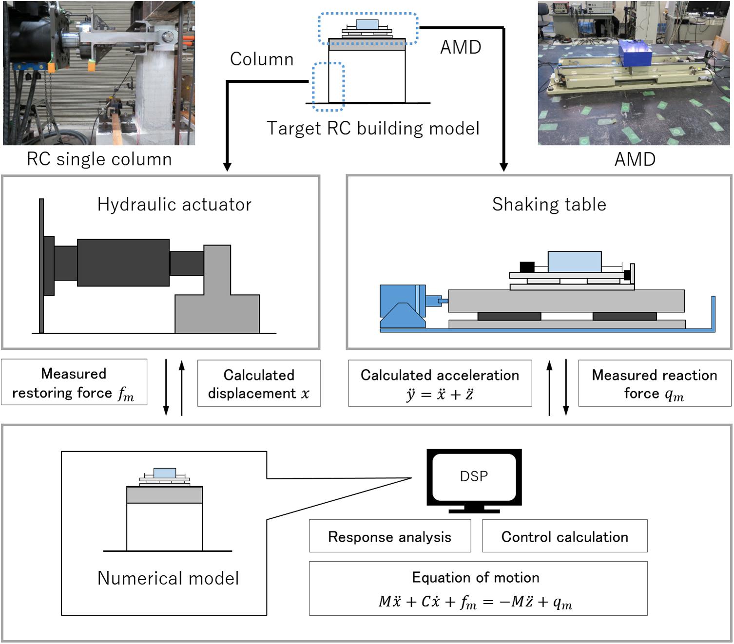
Figure 1. Conceptual diagram of the RTHS test using two-individual actuators.
Meanwhile, an actual displacement xm (m) and a restoring force fm (N) of the actual RC column specimen and an acceleration (m) and a reacting force qm (N) of the AMD are directly measured, and these interaction forces are reflected in the online model simulation. The internal model simulation determines the next target motion of the internal building model and the required control force of the AMD. The DSP controller gives a control signal to the AMD and drives instruction signals to the shaking table and the high-speed hydraulic actuator. These procedures are synchronized between the simulation part and the experimental substructures and are continued sequentially in real-time. This RTHS test is also required to synchronize the two actuators’ motions. Since this RTHS test system uses two actuators, which are placed at different laboratories, two DSP controllers (master and slave) are prepared, and communication between these DSPs is performed via LAN cables. Control operations in the RTHS test are executed every 0.002 s, and a signal time delay between two DSPs is less than this control time interval.
Figure 2A shows an overview of the AMD device used in this study (ωAD − 50ZZ1: produced by Tokkyokiki Co.), and Figure 2B depicts a schematic diagram of the AMD device composition. The AC servomotor of the AMD rotates a ball screw and drives an additional mass along with a liner guide in a horizontal direction. A control mode of the motor is set to a torque adjusting method. Specifications of the AMD device are shown in Table 1. As seen in Figure 2, the AMD is placed on a load measuring table, and a reacting force of the AMD can be directly measured by a load cell.
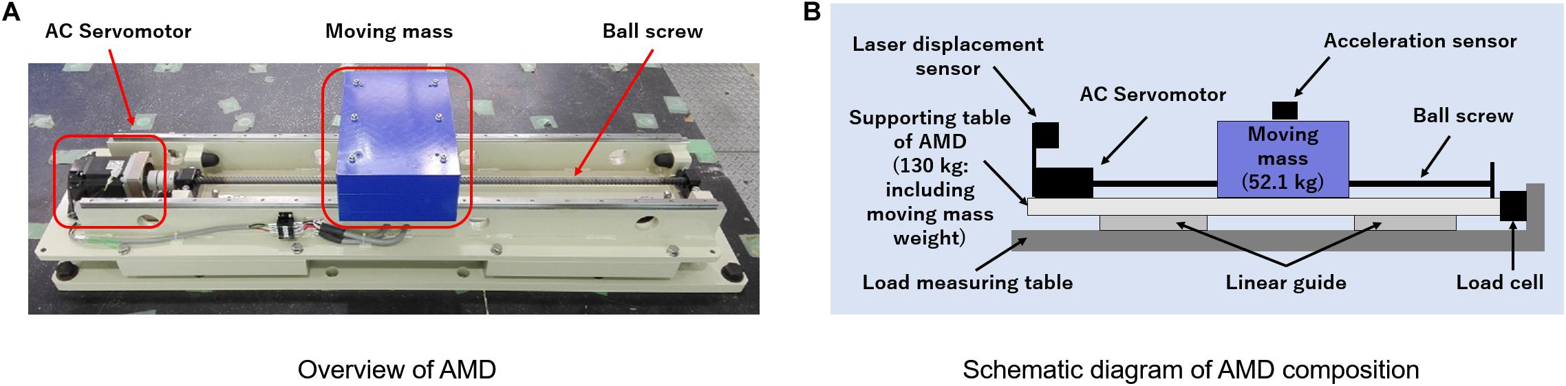
Figure 2. Configuration outlook of the test device of AMD. (A) Overview of AMD. (B) Schematic diagram of AMD composition.
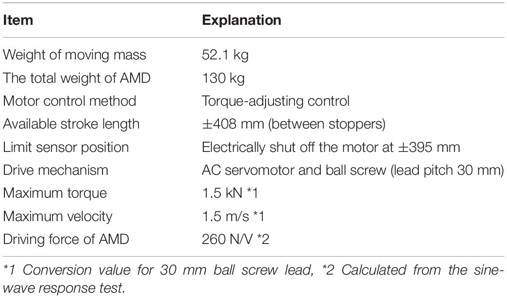
Table 1. Mechanical specification of the test device of AMD.
Outline of RC Column Specimen
Figure 3A depicts the configuration of the RC column specimen used in the RTHS test. The RC column specimen has a square cross-section of a width of 250 mm. A stub with a cross-section of 450 mm and a width of 350 mm is placed at the bottom of the specimen. Column height is 900 mm, and a loading point is set at the position of 750 mm from the top of the stub (or the bottom face of the column). Table 2 shows the material properties of rebar and the concrete cylinder test result for the RC column specimen. Stiffness of the column is calculated by considering a static loading test result. Figure 3B shows the relationship between lateral forces and horizontal deformations of the RC column specimen. This horizontal loading test was conducted by installing an axial force (axial force ratio of 0.2) in a vertical direction. Deformations of the specimen are given until they reach the maximum value of 0.01 rad (δmax = 7.5 mm); a loading history is cyclic, having deformation steps by an increment of 1.5 mm from the original position (δ = 1.5, 3.0. 4.5, 6.0, and 7.5 mm). Each deformation step is repeated three times in the loading sequence.
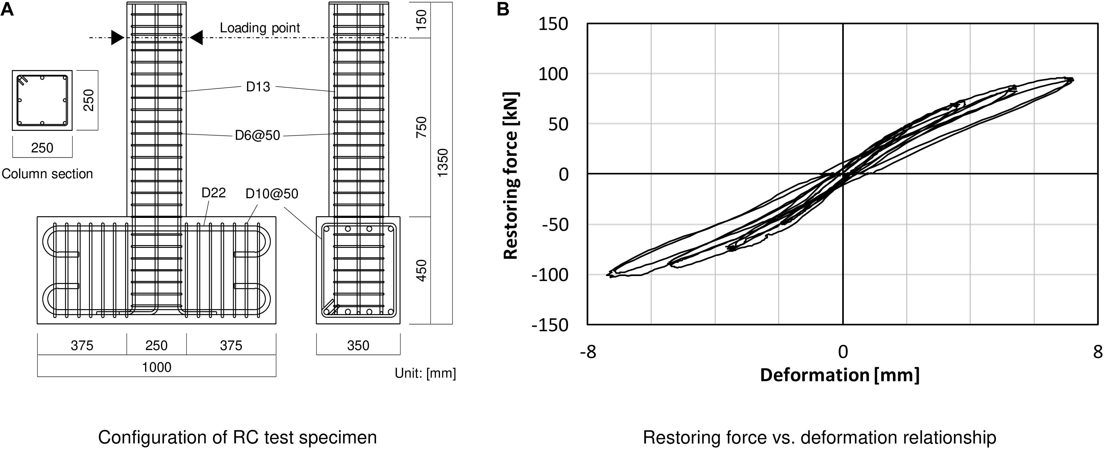
Figure 3. Configuration and static-loading test result of RC column test specimen. (A) Configuration of RC test specimen. (B) Restoring force vs. deformation relationship.
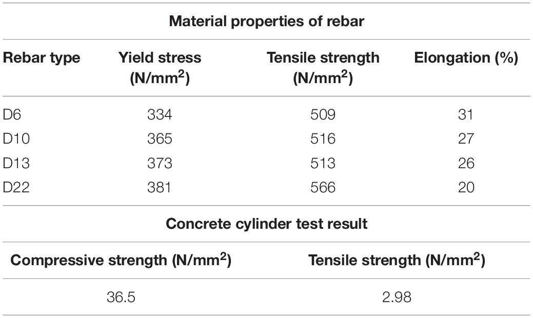
Table 2. Material properties of rebar and cylinder test results of concrete used in the RC column specimen.
Numerical Structural Model and Correspondence With the RC Column Specimen
Figure 4 shows the correspondence of the entire structural model and the experimental substructure (the actual RC column specimen) for the RTHS test. The actual RC column specimen is an extraction of a half part in the entire-length column; thus, its deformation δ (m) is also regarded as a half value of the entire-length column. Accordingly, the stiffness of the entire-length column k’ is considered to be a half value of the stiffness of the test specimen k, as explained in Figure 4A. The RTHS test supposes a single-story frame model as the entire target building for computer simulation; thus, a floor mass of the model is considered to be supported by four columns, as shown in Figure 4B. The story stiffness K (N/m) is also considered to be four times the single entire-length column’s stiffness and to be twice the actual RC column specimen’s stiffness (K = 4k’ = 2k). Every column is considered supporting 1/4 weight of the entire floor mass M (kg). The value of the floor’s mass of the target structural model is determined by giving the specified natural period of the numerical model. The initial structural parameters for the RTHS in this study are supposed, as shown in Table 3. During the RTHS test, the axial force of the actual RC column specimen is applied using PC tendons.
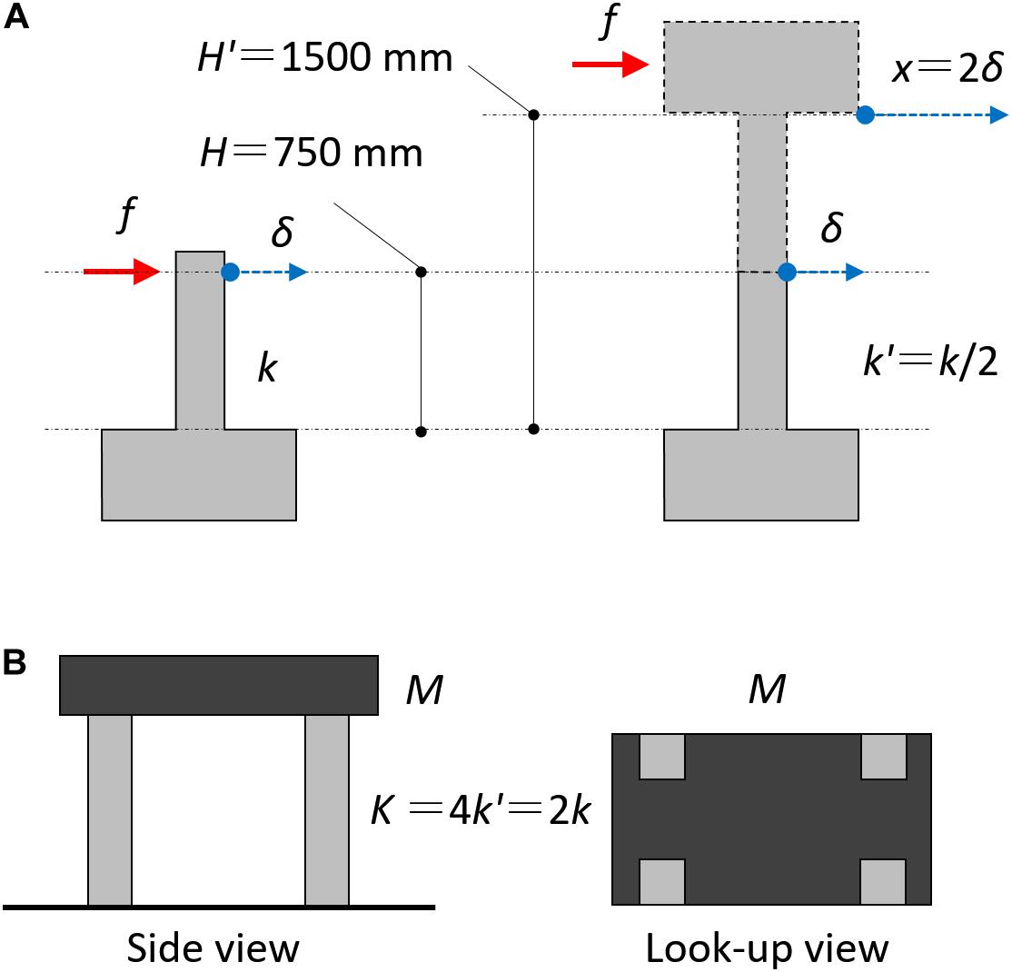
Figure 4. Simulation model of the entire RC structure for the RTHS test. (A) Correspondence of actual RC column specimen for the entire-length column. (B) Configuration of the entire RC frame model.
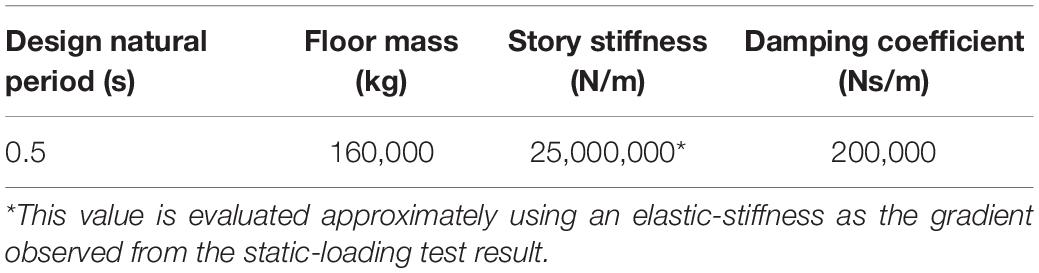
Table 3. Initial model parameters of the target structural model.
Time Delay Compensation Scheme for Hydraulic Actuator
Time Delay Evaluation
From a previous test, the hydraulic actuator, which is used for this RTHS test, is known to have a time delay of about 0.05 s between the time-histories of the desired displacement and the reproduced displacement depending on the hydraulic mechanism. The natural period of the target structural model in this study is approximately 0.5 s. Thus, the time delay of the hydraulic actuator is thought to become a severe factor causing the RTHS test performance to become unstable, because the response delay may unexpectedly cause inaccurate results in the online simulation. Therefore, a time delay compensator is designed to improve the performance of the hydraulic actuator. Firstly, a step response method as the authorized manner is used to identify a time delay model. In which, a control target is modeled as a time lag system and a first-order delay system.
As seen in Figure 5, a unit step input is applied to the hydraulic actuator, and the unit step response is measured. Herein, the gray line indicates the commanded displacement, and the red line indicates the measured response displacement. A gradient at the inflection point while increasing the step response is depicted with a broken blue line, and the time at which the tangent intersects the time axis is determined as a time lag L (s). Then, a progress time interval by which the tangent intersects the line in the steady-state of the step response after the time lag L is determined as a time constant T (s). These parameters are calculated as L = 0.014 s and T = 0.030 s from this step response. When the gain of the steady-state is α, the controlled object model, which includes the time delay, can be described by the transfer function in Eq. 1.
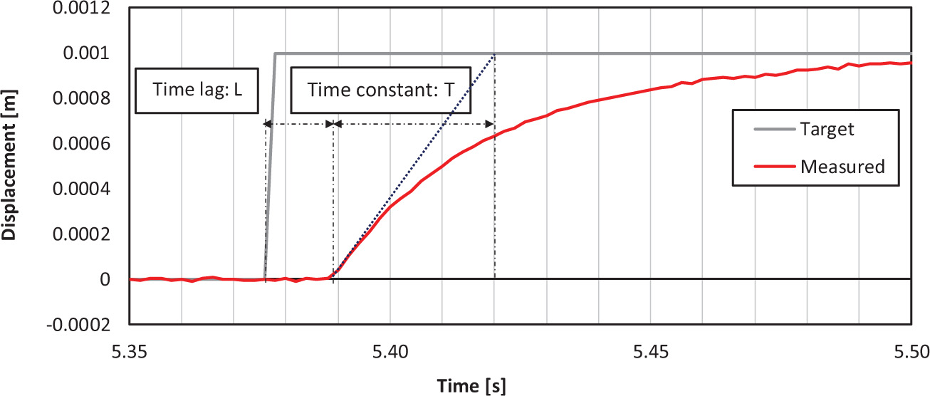
Figure 5. Time delay between commanded vs. measured displacements of hydraulic actuator under a unit step input.
Actuator Motion Compensation Using PID Control and Time Series Compensator
A PID control combines the three operations of a proportional operation, an integration operation, and a differential operation on a deviation signal e(t) between an output x(t) measured from a control target and a target value r(t); e(t) = x(t) − r(t). This way is considered to be a control method for determining an input u(t) for compensating the control target output. By applying a PID control method, it is possible to make a slow rise in the time constant increase sharply. The compensating input based on a PID control can be expressed by Eq. 2. Eq. 3 expresses the Laplace transform of Eq. 2, and describes the transfer characteristic between input and output in the s-region (Ziegler and Nichols, 1942). A proportional constant P = 1.93 (=0.9T/L), an integration constant I = 0.047 (=L/0.3), and a differential constant D = 0 are used in this RTHS test to compensate for the hydraulic actuator motion.
The PID controller is installed for the error correction between the target signal and the measured signal of the hydraulic actuator displacement. To improve the actuator motion more effectively, the compensator using a predictive response expressed by a time series is also introduced to the control operation of the hydraulic actuator (Chae et al., 2013). By evaluating the value of the time delay τ (s), the target input for the feedforward compensation related to the referential value after the time interval τ is considered. At the time t (s), the target displacement after the time interval τ can be expressed as r(t + τ). Using the Tayler series, this expression can be expanded to a power series of τ.
In this study, approximately considering the first-order term in the Tayler series, the following TSC is installed to drive the hydraulic actuator in parallel with the PID controller (Eq. 5). The block diagram, including these actuator motion compensators, is shown in Figure 6.
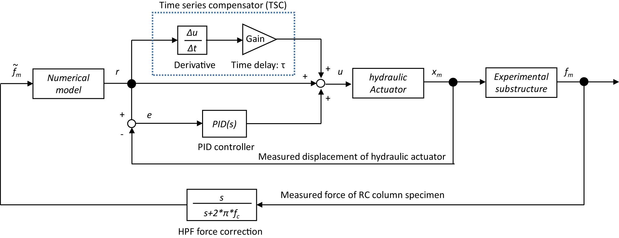
Figure 6. Block diagram of actuator motion compensator and force correction.
In Figure 7A, the commanded value, the measured value under compensation, and the measured value without compensation are compared when a sinusoidal wave is used as an input. It was confirmed that the delay time, which was about 0.046 s without compensation, is reduced to about 0.014 s with compensation. Figure 7B shows the commanded displacement and the measured displacement of the hydraulic actuator using the PID control and TSC when a random wave is applied. In this case, the time difference between the commanded displacement and the measured displacement is as small as about 0.014 s, and the effectiveness of the PID control and TSC can be confirmed. Although the PID and TSC blocks in Figure 6 may work for reducing the permanent time delay of the servo-hydraulic actuator’s displacement, the desired performance level of the RTHS compared to the general studies has not yet been achieved. Therefore, a phase-matching scheme between the simulation time of the computer model and the measurement data of the generated force is additionally considered to touch up the RTHS performance.
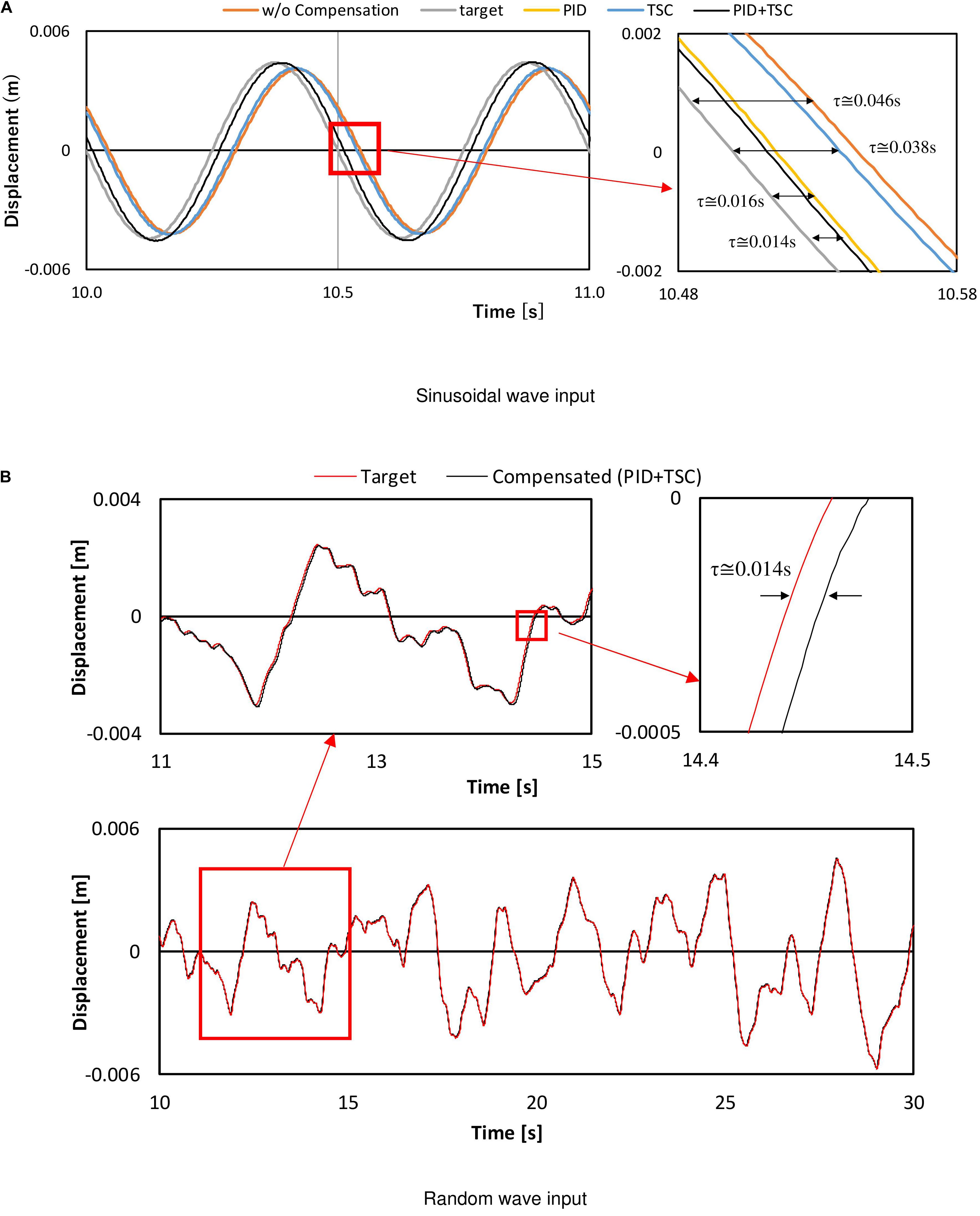
Figure 7. Displacement compensation results of hydraulic actuator motion using PID and TSC. (A) Sinusoidal wave input. (B) Random wave input.
Rths Test Results
Force Correction Method for the Online Simulation
Through the previous investigation of displacement compensation, the time delay of the hydraulic actuator can be shortened, but a small time delay has remained. In this study, the RTHS performance is improved using an alternative method based on a force correction scheme, which is installed to the force-response feedback signal from the hydraulic actuator. A single-pole HPF is applied to the phase-leading correction of the measured forces before the feedback to the internal numerical simulations. The formula of HPF force correction is expressed by the transform function of Eq. 6.
In which, fc (Hz) is a cut-off frequency, which needs to adjust according to the system phase delay. This HPF has a phase-shift of π/4 at the cut-off frequency fc. The RTHS setup in this study has kept a residual time delay of about 0.014 s in the displacement generation of the hydraulic actuator. In the following part, the method to compensate for this considerable time delay effect indirectly for the computer calculation of the RTHS is considered.
The block diagram of the force correction process is shown in Figure 6. Figure 8 shows the restoring force vs. displacement relationship of the actual RC column, and Figures 8A,B are the results of applying the value of the cut-off frequency fc = 0.5 and 0.2 Hz, respectively. The target structural model was designed as the natural frequency of 2 Hz in this study, and the most predominant vibration response of the model must be caused around 2 Hz in the RTHS test. Thus, the angle of phase-lead can be calculated by φ = tan−1 (fc/f) [rad] and a time-lead is given by Δt = φ/2πf (s). When fc = 0.5 and 0.2 Hz, the values of Δt are expected as about 0.020 and 0.008 s, respectively. In Figure 8, the figures on the left correspond to the measured force fm vs. the measured displacement xm, the figures in the middle correspond to the measured force fm vs. the target displacement xr, and the figures on the right correspond to the measured force with HPF vs. the target displacement xr, respectively. The input motion is El Centro NS of 20% scale factor; thus, the range of the RC column’s response is regarded as mostly inside the linear region. In these test cases, the same RC column specimen is repeatedly used, the tangential stiffness of the specimen has been changing gradually through each test case. As seen in the figures in the middle of Figure 8, the hysteresis curve of the internal simulation draws a negative loop if the measured force signal was directly fed back to the simulation. However, as seen in the figures on the right in Figure 8B, the HPF can correct the phase delay of the force response, and the negative loop behavior can be effectively corrected. By comparing the figures on the left and the right in Figure 8B, the hysteresis curve of the HPF-filtered force vs. the target displacement xr can be appropriately corresponded to the hysteresis curve of the measured force fm vs. the measured displacement xm, when the cut-off frequency fc is selected at 0.2 Hz, in this test condition.
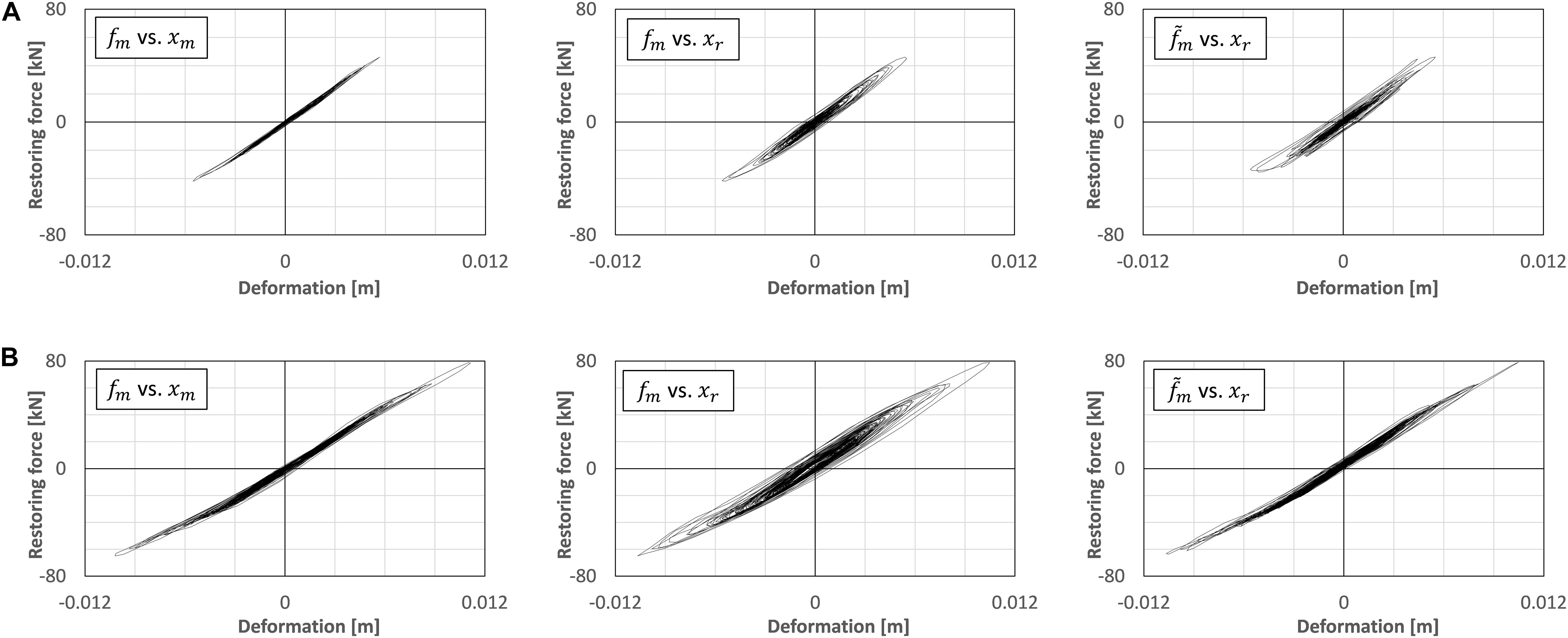
Figure 8. Hysteresis of restoring force vs. deformation of RC column specimen. (A) fc = 0.5 Hz. (B) fc = 0.2 Hz.
The error of displacement tracking is investigated in cases using different earthquake inputs. To evaluate the degree of tracking error in the RTHS, the following indications which are introduced by Ou et al. in their previous study (Ou et al., 2015) are used.
where Dm is measured displacement, Dd is desired displacement, and De = Dm − Dd is the tracking error. max(Dd) means the maximum of the absolute value of the desired displacement. Table 4 lists the error indications for each case under Eqs 7–9. All cases were conducted under the cut-off frequency fc = 0.2 Hz for the HPF. In this table, “Takatori” is the ground motion record observed at the JR Takatori Railway Station during the South Hyogo Prefecture Earthquake in 1995, and “JMA Kobe” is the ground motion record observed at the Kobe Local Meteorological Office of Japan Meteorological Agency (JMA) during the South Hyogo Prefecture Earthquake in 1995. The influence due to the residual time delay of the hydraulic actuator motion was observed in the values of error indications, especially, in the value of J2. However, as seen in the overall results, the difference depending on the earthquake inputs is considered to be small among these test cases.
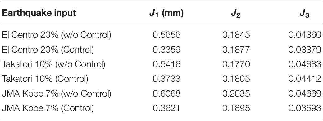
Table 4. Error indications of RTHS performance under different earthquake inputs.
Comparison of RTHS Test and Numerical Analysis Results Without AMD
In the previous section, the effect of a compensator for the time delay of the hydraulic actuator was observed. In this section, the reproducibility of the RTHS test system is investigated. Figure 9A shows the comparison between the measured responses in the RTHS test and the pure-simulation results. The experimental data are processed through the low-pass filter to remove the high-frequency noise. The numerical simulation is conducted by supposing the linear model; thus, the stiffness of the simulation model is considered as the tangential ratio of the maximum restoring force for the maximum displacement of the RC column in the corresponding RTHS test case. As seen in these figures, it is found that the RTHS test results are slightly larger than the numerical responses, but the phase correlation is assured between the RTHS and the pure-simulation results. These differences are increased in the shaking-table motion to reproduce a floor acceleration compared with the hydraulic actuator motion to reproduce an inter-story displacement. As the reason for this, it is considered that the negative damping effects caused by the residual time delay in the actuators influences the decrease of the damping effects of the entire system in the RTHS test.
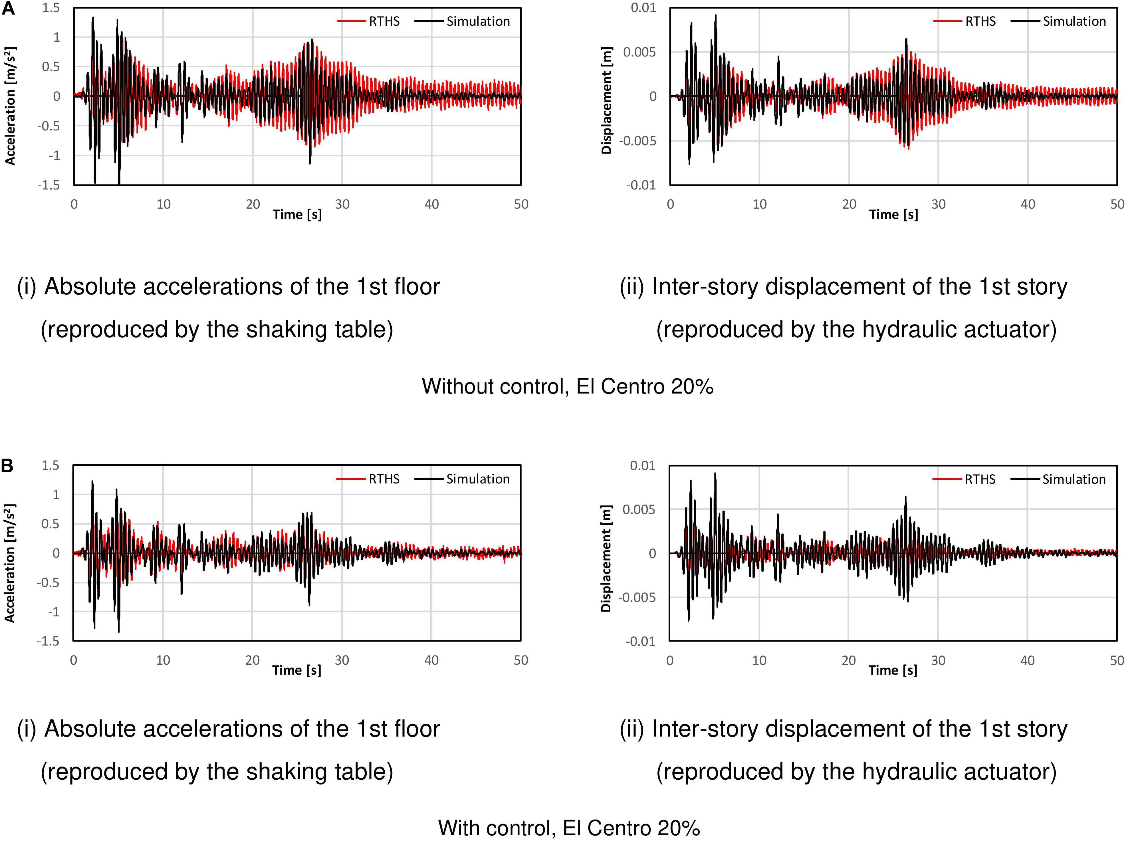
Figure 9. Measured responses of RTHS test vs. pure-simulation results. (A) Without control, El Centro 20%, (i) Absolute accelerations of the 1st floor (reproduced by the shaking table) and (ii) Inter-story displacement of the 1st story (reproduced by the hydraulic actuator). (B) With control, El Centro 20%, (i) Absolute accelerations of the 1st floor (reproduced by the shaking table) (ii) Inter-story displacement of the 1st story (reproduced by the hydraulic actuator).
Comparison of RTHS Test and Numerical Analysis Results Using AMD
Figure 9B shows the comparison of the responses under the velocity feedback control using the AMD. Control forces are given by the rule of the equivalent feedback gain G = 120,000 Ns/m, which is corresponding to the damping factor of about 3% for the target building model. As seen in these figures, it is found that the RTHS test results have moderate agreements with the pure-simulation results on both of the shaking table motion and the hydraulic actuator motion in the case under control using AMD. Figure 10 shows the comparison of the RTHS test results of the controlled case using AMD and the case without control. Figure 10A corresponds to the case, the input motion is El Centro NS of 20% scale factor. Figure 10B corresponds to the case, the input motion is Takatori NS of 10% scale factor. By observing these figures, it is confirmed that the control performance of the AMD can be adequately reflected in the RTHS test results as the reduction of the inter-story displacement and the floor acceleration.
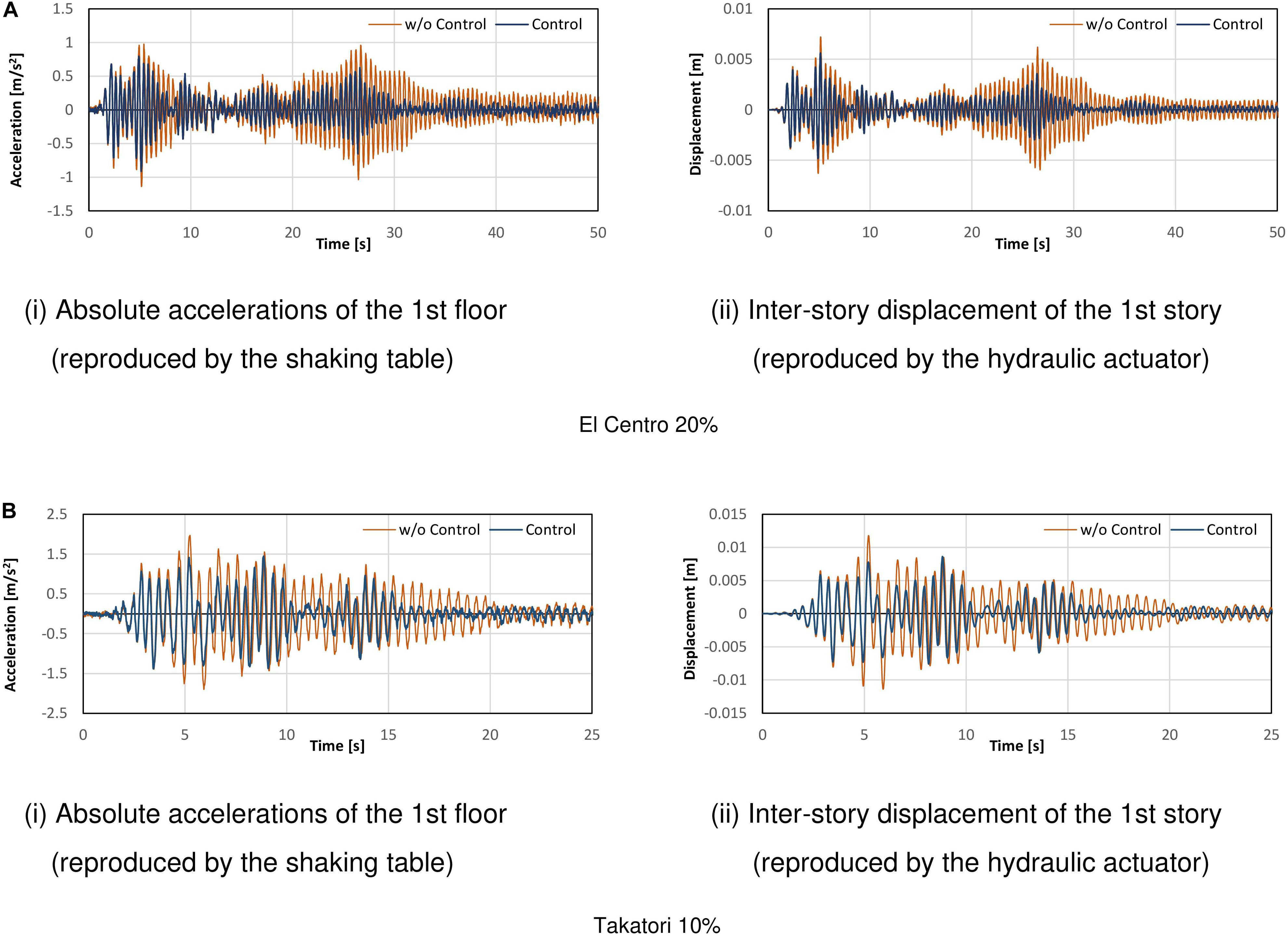
Figure 10. Comparison of responses between with/without control in the RTHS test. (A) El Centro 20%, (i) Absolute accelerations of the 1st floor (reproduced by the shaking table) and (ii) Inter-story displacement of the 1st story (reproduced by the hydraulic actuator). (B) Takatori 10%, (i) Absolute accelerations of the 1st floor (reproduced by the shaking table) and (ii) Inter-story displacement of the 1st story (reproduced by the hydraulic actuator).
Imposed force-deformation relationships in the strong non-linear region of the actual RC column specimen are compared, as seen in Figures 11A,B. Figures 11A,B are the RTHS test results under the input motion of El Centro of 50 and 80% scale factors, respectively. The HPF with the cut-off frequency fc = 0.2 Hz is applied to the force feedback signal in these test cases. In Figure 11, the figures on the left correspond to the measured force fm vs. the measured displacement xm, the figures on the middle correspond to the measured force fm vs. the target displacement xr, and the figures on the right correspond to the measured force with HPF vs. the target displacement xr, respectively. As seen in the figures on the left in Figure 11, the RC column has moved into the inelastic region, and the force-deformation relationships have drawn hysteresis loops. By comparing the figures on the left and the middle in Figures 11A or B, the hysteresis loops of the internal simulations draw different loops from the correct hysteresis loops. There is the time delay’s influence on the hydraulic actuator as long as the measured force signal was directly fed back to the internal simulation. However, by comparing the figures on the left and the right in Figures 11A or B, the hysteresis loops of the HPF-filtered force vs. the target displacement xr correspond to the hysteresis loops of the measured force fm vs. the measured displacement xm in the non-linear region.
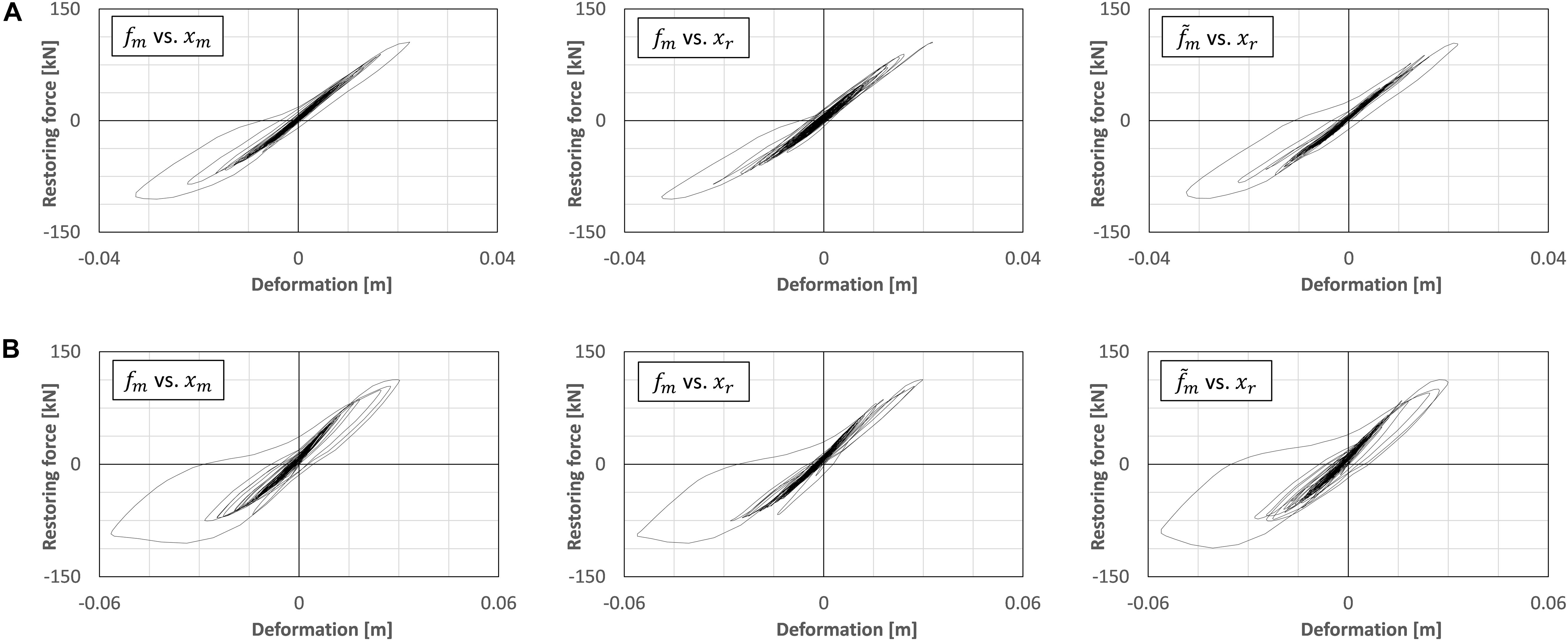
Figure 11. Hysteresis of restoring force vs. deformation of RC column specimen. (A) fc = 0.2 Hz, El Centro NS 50%. (B) fc = 0.2 Hz, El Centro NS 80%.
Conclusion and Future Works
In this study, an RTHS test using two-individual actuators was conducted. A high-speed hydraulic actuator was used to deform the RC column test specimen, and a shaking table was used to reproduce the acceleration response of the AMD-equipped floor. The findings of this study are summarized as follows.
1. To improve the system performance of the RTHS test, a time delay compensation of the hydraulic actuator was designed. The combination of the PID controller and the TSC method was installed for the operation of the hydraulic actuator. In this study’s setup, the permanent time delay about 0.046 s could be shortened to about 0.014 s by the PID + TSC compensator. To achieve a stable performance of the RTHS test, the additional compensation scheme was required for eliminating the influence due to this residual time delay.
2. To improve a numerical simulation of the internal model in the RTHS under the existence of the residual time delay, the measured force to feedback to the simulation was corrected by using the HPF as an input signal. The filter parameter of HPF was considered as the phase-lead angle can be adjusted to eliminate the influence of the residual time delay during the steady oscillation depending on the natural period of the target structural model. By introducing the appropriate HPF, it was observed the force-displacement relationship in the internal simulations correspond moderately to the actual force-displacement relationship, which was directly measured in the actual test specimen.
3. The combination of the PID + TSC compensator for the displacement tracking and the simple phase-matching method using HPF for the measured force correction enabled the stable RTHS operation even if the considerable time delay remained. These results were confirmed not only in the linear region of the RC column specimen but also in the non-linear region in the range of this test setup.
4. The RTHS tests could be operated under synchronization between the hydraulic actuator and the shaking-table. Comparing the reproduced responses of the RTHS tests to the pure-simulation responses, there are moderate agreements, in particular for the case under control using AMD. A moderate difference between the RTHS tests and the pure-simulations was observed in the case without control. This considers that the negative damping effect depending on the residual time delay of the hydraulic actuator was rather sensitive in the low-damping condition of the internal model.
These findings have resulted from the limited test conditions and have not reached general conclusions yet. However, this approach of developing the RTHS test environment, which can generate the floor response of RC frame constructions, may contribute to potential users requiring rapid and simple test tools to conduct the performance evaluation of mass damper devices. Future work on the RTHS using two-individual actuators: the further improvement of the RTHS performance in the highly non-linear range of the RC substructure, the more test variations of the seismic inputs or the natural frequencies of the entire model, and the application to the multi-degree-freedom model, should be implemented while associating with the state-of-the-art methodologies of the RTHS.
Data Availability Statement
The datasets supporting the conclusions of this article will be made available on request to the corresponding author.
Author Contributions
YM supervised the research, conducted the RTHS experiment and data analysis, and wrote the manuscript. AY conducted the RTHS experiment and data analysis. KF conducted the RTHS experiment and control program operation. TF discussed the results and prepared the actual RC column test specimens. HF discussed the results and supervised the research. All authors contributed to the article and approved the submitted version.
Funding
Part of the present study was supported by the Grants-in-Aid for Scientific Research (JSPS KAKENHI No. 18H01587) and JSPS Grant No. R2904 in the program for Fostering Globally Talented Researchers.
Conflict of Interest
The authors declare that the research was conducted in the absence of any commercial or financial relationships that could be construed as a potential conflict of interest.
References
Abbiati, G., Bursi, O. S., Caperan, P., Sarno, L. D., Molina, F. J., Paolacci, F., et al. (2015). Hybrid simulation of a multi-span RC viaduct with plain bars and sliding bearings. Earthqu. Engin. Struct. Dynam. 44, 2221–2240. doi: 10.1002/eqe.2580
Ahmadizadeh, M., Mosqueda, G., and Reinhorn, A. M. (2008). Compensation of actuator delay and dynamics for real-time hybrid structural simulation. Earthqu. Engin. Struct. Dynam. 37, 21–42. doi: 10.1002/eqe.743
Cardone, D., and Flora, A. (2016). An alternative approach for the seismic rehabilitation of existing RC buildings using seismic isolation. Earthqu. Engin. Struct. Dynam. 45, 91–111. doi: 10.1002/eqe.2618
Carrion, J. E., and Spencer, B. F. Jr. (2006). “Real-time hybrid testing using model-based delay compensation,” in Proc. of the 4th International Conference on Earthquake Engineering, Taipei, (Berlin: Springer), 1–11. doi: 10.1002/eqe.2189
Carrion, J. E., Spencer, B. F. Jr., and Phillips, B. M. (2009). Real-time hybrid simulation for structural control performance assessment. Earthqu. Engin. Engin. Vibr. 8, 481–492. doi: 10.1007/s11803-009-9122-4
Chae, Y. B., Kazemibidokhti, K., and Ricles, J. M. (2013). Adaptive time series compensator for delay compensation of servo-hydraulic actuator systems for real-time hybrid simulation. Earthqu. Engin. Struct. Dynam. 42, 1697–1715. doi: 10.1002/eqe.2294
Chae, Y. B., Lee, J. H., Park, M. S., and Kim, C. Y. (2018a). Real-time hybrid simulation for an RC bridge pier subjected to both horizontal and vertical ground motions. Earthqu. Engin. Struct. Dynam. 47, 1673–1679. doi: 10.1002/eqe.3042
Chae, Y. B., Rabiee, R., Dursun, A., and Kim, C. Y. (2018b). Real-time force control for servo-hydraulic actuator systems using adaptive time series compensator and compliance springs. Earthqu. Engin. Struct. Dynam. 47, 854–871. doi: 10.1002/eqe.2994
Chae, Y. B., Park, M. S., Kim, C. Y., and Park, Y. S. (2017). Experimental study on the rate-dependency of reinforced concrete structures using slow and real-time hybrid simulations. Engin. Struct. 132, 648–658. doi: 10.1016/j.engstruct.2016.11.065
Chen, P. C., and Tsai, K. C. (2013). Dual compensation strategy for real-time hybrid testing. Earthqu. Engin. Struct. Dynam. 42, 1–23.
Darby, A. P., Williams, M. S., and Blakeborough, A. (2002). Stability and delay compensation for real-time substructure testing. J. Engin. Mechan. ASCE. 128, 1276–1284. doi: 10.1061/(ASCE)0733-93992002128:121276
Elias, S., and Matsagar, V. (2017). Research developments in vibration control of structures using passive tuned mass dampers. Annu. Rev. Contr. 44, 129–156. doi: 10.1016/j.arcontrol.2017.09.015
Elias, S., and Matsagar, V. (2019). Seismic vulnerability of a non-linear building with distributed multiple tuned vibration absorbers. Struct. Infrastruct. Engin. Mainten. 15, 1–16. doi: 10.1080/15732479.2019.1602149
Fushihara, K., Yokoyama, A., and Mukai, Y. (2020). “Real-time hybrid test system using shaking table for performance evaluation of active mass damper,” in 17th World Conference on Earthquake Engineering, (Sendai: AEES), (2g-144) 1–9.
Gao, X., Castaneda, N., and Dyke, S. J. (2013). Real time hybrid simulation: from dynamic system, motion control to experimental error. Earthq. Engin. Struct. Dynam. 42, 815–832. doi: 10.1002/eqe.2246
Goorts, K., Ashasi-Sorkhabi, A., and Narasimhan, S. (2017). Deployable Active Mass Dampers for Vibration Mitigation in Lightweight Bridges. J. Struct. Engin. 143, 4017159–4017151. doi: 10.1061/(ASCE)ST.1943-541X.0001921
Horiuchi, T., Inoue, M., and Konno, T. (2000). “Development of a real-time hybrid experimental system using a shaking table,” in Proc. of the 12th World Conference on Earthquake Engineering, Auckland, 1–8.
Horiuchi, T., Inoue, M., Konno, T., and Namita, Y. (1999). Real-time hybrid experimental system with actuator delay compensation and its application to a piping system with energy absorber. Earthqu. Engin. Struct. Dynam. 28, 1121–1141. doi: 10.1002/(SICI)1096-9845(199910)28
Huff, T. (2016). Estimating Residual Seismic Displacements for Bilinear Oscillators. Pract. Period. Struct. Des. Construct. 21:282. doi: 10.1061/(ASCE)SC.1943-5576.0000282
Ito, M., Fujitani, H., Oknano, M., Nishikawa, K., and Mosqueda, G. (2018). “Real-time hybrid test of structures with a tuned mass damper using shaking table,” in Proc. of the 7th World Conference on Structural Control and Monitoring, (Qingdao: Wiley), 1263–1271.
Jaafari, C., and Mohammadi, J. (2018). Floor Vibration Control as a Serviceability Requirement in Design Standards and Practices: Review. Pract. Period. Struct. Des. Construct. 23:07019001. doi: 10.1061/(ASCE)SC.1943-5576.0000361
Kazantzi, A. K., and Vamvatsikos, D. (2020). Seismic and Vibration Performance Rehabilitation for an Industrial Steel Building. Pract. Period. Struct. Des. Construct. 25:475. doi: 10.1061/(ASCE)SC.1943-5576.0000475
Lee, S. K., Park, E. C., Min, K. W., and Park, J. H. (2007). Real-time substructuring technique for the shaking table test of upper substructures. Engin. Struct. 29, 2219–2232. doi: 10.1016/j.engstruct.2006.11.013
Liu, J., Dyke, S. J., Liu, H. J., Gao, X. Y., and Phillips, B. (2013). A novel integrated compensation method for actuator dynamics in real-time hybrid structural testing. Struct. Contr. Health Monit. 20, 1057–1080. doi: 10.1002/stc.1519
Matsagar, V. A., and Jangid, R. S. (2008). Base Isolation for Seismic Retrofitting of Structures. Pract. Period. Struct. Des. Construct. 13, 175–185. doi: 10.1061/(ASCE)1084-0680200813:4(175)
Mei, Z., Wu, B., Bursi, O. S., Xu, G. S., Wang, Z., Wang, T., et al. (2019). Hybrid simulation with online model updating: Application to a reinforced concrete bridge endowed with tall piers. Mechan. Sys. Sign. Proc. 123, 533–553. doi: 10.1016/j.ymssp.2019.01.009
Miyamoto, H. K., Gilani, A. S. J., Garza, J., and Mahin, S. A. (2010). Seismic Retrofit of a Landmark Structure Using a Mass Damper, Structure Congress 2010. ASCE Orlando 19, 2291–2302. doi: 10.1061/41130(369)208
Mukai, Y., Miki, Y., Uchida, S., Fujitani, H., and Ito, M. (2018). “Real-time hybrid simulator of soil-structure interaction system by using shaking table,” in Proc. of 11th U.S. National Conference on Earthquake Engineering, (California: Los Angeles), 1–11. doi: 10.1155/2017/1291265
Nakai, T., Kurino, H., Yaguchi, T., and Kano, N. (2019). Control effect of large tuned mass damper used for seismic retrofitting of existing high-rise building. Japan Architect. Rev. 2, 269–286. doi: 10.1002/2475-8876.12100
Neild, S. A., Stoten, D. P., Drury, D., and Wagg, D. J. (2005). Control issues relating to real-time substructuring experiments using a shaking table. Earthq. Engin. Struct. Dynam. 34, 1171–1192. doi: 10.1002/eqe.473
Ou, G., Ozdagli, A. I., Dyke, S. J., and Wu, B. (2015). Robust integrated actuator control: experimental verification and real-time hybrid-simulation implementation. Earthqu. Engin. Struct. Dynam. 44, 441–460. doi: 10.1002/eqe.2479
Phillips, B. M., and Spencer, B. F. Jr. (2013). Model-Based Feedforward-Feedback Actuator Control for Real-Time Hybrid Simulation. J. Struct. Engin. 139, 1206–1214. doi: 10.1061/(ASCE)ST.1943-541X.0000606
Shao, X., Reinhorn, A. M., and Sivaselvan, M. V. (2011). Real time hybrid simulation using shake tables and dynamic actuators. J. Struct. Engin. ASCE. 137, 748–760. doi: 10.1061/(ASCE)ST.1943-541X.0000314
Wang, J., and Zhao, H. (2018). High Performance Damage-Resistant Seismic Resistant Structural Systems for Sustainable and Resilient City: A Review. Shock Vibr. 2018:8703697. doi: 10.1155/2018/8703697
Wang, Q., Wang, J. T., Jin, F., Chia, F. D., and Zhang, C. H. (2011). Real-time dynamic hybrid testing for soil-structure interaction analysis. Soil Dynam. Earthqu. Engin. 31, 1690–1702. doi: 10.1016/j.soildyn.2011.07.004
Xu, H. B., Zhang, C. W., Li, H., and Ou, J. P. (2014). Real-time hybrid simulation approach for performance validation of structural active control systems: a linear motor actuator based active mass driver case study. Struct. Contr. Health Monit. 21, 574–589. doi: 10.1002/stc.1585
Yoshida, S., Fujitani, F., Mukai, Y., and Ito, M. (2018). Real-time hybrid simulation of semi-active control using shaking table: Proposal and verification of a testing method for mid-story isolated buildings. Japan Architect. Rev. 1, 221–234. doi: 10.1002/2475-8876.12034
Zhang, C. X., and Jiang, N. (2017). A shaking table real-time substructure experiment of an equipment-structure-soil interaction system. Adv. Mechan. Engin. 9, 1–12. doi: 10.1177/1687814017724090
Zhang, R. Y., Lauenstein, P. V., and Phillips, B. M. (2016). Real-time hybrid simulation of a shear building with a uni-axial shake table. Engin. Struct. 119, 217–229. doi: 10.1016/j.engstruct.2016.04.022
Zhu, F., Wang, J. T., Jin, F., and Lu, L. Q. (2017). Real-time hybrid simulation of full-scale tuned liquid column dampers to control multi-order modal responses of structures. Engin. Struct. 138, 74–90. doi: 10.1016/j.engstruct.2017.02.004
Keywords: real-time hybrid simulation, shaking table, hydraulic actuator, active mass damper, time delay compensator, reinforced concrete structure
Citation: Mukai Y, Yokoyama A, Fushihara K, Fujinaga T and Fujitani H (2020) Real-Time Hybrid Test Using Two-Individual Actuators to Evaluate Seismic Performance of RC Frame Model Controlled by AMD. Front. Built Environ. 6:145. doi: 10.3389/fbuil.2020.00145
Received: 31 May 2020; Accepted: 03 August 2020;
Published: 04 November 2020.
Edited by:
Wei Song, University of Alabama, United StatesReviewed by:
Ge Ou, The University of Utah, United StatesSaid Elias Rahimi, University of Iceland, Iceland
Copyright © 2020 Mukai, Yokoyama, Fushihara, Fujinaga and Fujitani. This is an open-access article distributed under the terms of the Creative Commons Attribution License (CC BY). The use, distribution or reproduction in other forums is permitted, provided the original author(s) and the copyright owner(s) are credited and that the original publication in this journal is cited, in accordance with accepted academic practice. No use, distribution or reproduction is permitted which does not comply with these terms.
*Correspondence: Yoichi Mukai, eW11a2FpQHBvcnQua29iZS11LmFjLmpw