 Lelli Van Den Einde1
 Joel P. Conte1*
 José I. Restrepo1
 Ricardo Bustamante1
 Marty Halvorson2
 Tara C. Hutchinson1
 Chin-Ta Lai1
 Koorosh Lotfizadeh1J. Enrique Luco1
 Machel L. Morrison1
 Gilberto Mosqueda1
 Mike Nemeth2
 Ozgur Ozcelik3
 Sebastian Restrepo4
 Andrés Rodriguez1
 P. Benson Shing1Brad Thoen2
 Georgios Tsampras1
- 1NHERI@UC San Diego Experimental Facility, Department of Structural Engineering, Jacobs School of Engineering, University of California, San Diego, La Jolla, CA, United States
- 2Advanced Systems Group, MTS Systems Corporation, Eden Prairie, MN, United States
- 3Department of Civil Engineering, Dokuz Eylul University, Izmir, Turkey
- 4Department of Mechanical Engineering, The University of Sydney, Sydney, NSW, Australia
Since its commissioning in 2004, the UC San Diego Large High-Performance Outdoor Shake Table (LHPOST) has enabled the seismic testing of large structural, geostructural and soil-foundation-structural systems, with its ability to accurately reproduce far- and near-field ground motions. Thirty-four (34) landmark projects were conducted on the LHPOST as a national shared-use equipment facility part of the National Science Foundation (NSF) Network for Earthquake Engineering Simulation (NEES) and currently Natural Hazards Engineering Research Infrastructure (NHERI) programs, and an ISO/IEC Standard 17025:2005 accredited facility. The tallest structures ever tested on a shake table were conducted on the LHPOST, free from height restrictions. Experiments using the LHPOST generate essential knowledge that has greatly advanced seismic design practice and response predictive capabilities for structural, geostructural, and non-structural systems, leading to improved earthquake safety in the community overall. Indeed, the ability to test full-size structures has made it possible to physically validate the seismic performance of various systems that previously could only be studied at reduced scale or with computer models. However, the LHPOST's limitation of 1-DOF (uni-directional) input motion prevented the investigation of important aspects of the seismic response of 3-D structural systems. The LHPOST was originally conceived as a six degrees-of-freedom (6-DOF) shake table but built as a single degree-of-freedom (1-DOF) system due to budget limitations. The LHPOST is currently being upgraded to 6-DOF capabilities. The 6-DOF upgraded LHPOST (LHPOST6) will create a unique, large-scale, high-performance, experimental research facility that will enable research for the advancement of the science, technology, and practice in earthquake engineering. Testing of infrastructure at large scale under realistic multi-DOF seismic excitation is essential to fully understand the seismic response behavior of civil infrastructure systems. The upgraded 6-DOF capabilities will enable the development, calibration, and validation of predictive high-fidelity mathematical/computational models, and verifying effective methods for earthquake disaster mitigation and prevention. Research conducted using the LHPOST6 will improve design codes and construction standards and develop accurate decision-making tools necessary to build and maintain sustainable and disaster-resilient communities. Moreover, it will support the advancement of new and innovative materials, manufacturing methods, detailing, earthquake protective systems, seismic retrofit methods, and construction methods. This paper will provide a brief overview of the 1-DOF LHPOST and the impact of some past landmark projects. It will also describe the upgrade to 6-DOF and the new seismic research and testing that the LHPOST6 facility will enable.
Introduction
The upgrade of the University of California at San Diego Large High Performance Outdoor Shake Table (LHPOST) funded by the National Science Foundation (NSF) Natural Hazard Engineering Research Infrastructure (NHERI) network from one to six degrees of freedom (6-DOF) is critical for the economical design, construction, and implementation of improved seismic mitigation strategies. Since its commissioning in 2004, the LHPOST has enabled the seismic testing of large structural, geostructural and soil-foundation-structural systems, with its ability to accurately reproduce far- and near-field ground motions. Thirty-four (34) landmark projects were conducted on the LHPOST as an NSF-sponsored national shared-use Network for Earthquake Engineering Simulation (NEES) and currently NHERI equipment facility. The LHPOST has the largest payload capacity in the world and ranks second in size after Japan's E-Defense shake table. The tallest structures ever tested on a shake table have used the LHPOST, which has no roof overhead, and is therefore free from height or crane capacity restrictions. Tall cranes and heavy lifting equipment can easily be used to construct full-scale buildings and other structures. The ability to test full-size structures has made it possible to physically validate the seismic performance of various systems that previously could only be studied at reduced scale or with computer models. However, the LHPOST's limitation of 1-DOF (uni-directional) input motion has prevented the investigation of many important aspects of the seismic response performance of 3-D structural systems. Currently, E-Defense has the only large-capacity 6-DOF shake table in the world. The LHPOST was designed initially as a 6-DOF shake table but built as a 1-DOF system due to budget limitations. The current upgrade of the LHPOST to 6-DOFs, termed LHPOST6 thereafter, is funded by a grant from the NSF and additional resources from UC San Diego. The LHPOST6 will be the largest shake table facility in the U.S. and the second largest in the world that will address research needs pertinent to design and construction practices in the U.S. and worldwide.
The LHPOST6 will provide a unique, large-scale, high-performance, experimental research facility that will enable research for the advancement of the science, technology, and engineering practice in earthquake disaster mitigation and prevention. Testing of infrastructure at large scale under realistic multi-DOF seismic excitation is essential to fully understand the seismic response behavior of civil infrastructure systems, calibrate, validate, and improve mathematical models, and develop and verify effective methods for earthquake disaster mitigation. Research conducted using the LHPOST6 will improve design codes and construction standards, validate high-fidelity computational models, and develop accurate decision-making tools necessary to build and maintain sustainable and disaster-resilient communities. Moreover, it will support the advancement of new and innovative materials, detailing, and construction methods.
Research activities using the LHPOST6 will broadly impact science, engineering, and education. Next-generation researchers, educators, and practitioners will be trained and will achieve a fundamental and holistic understanding of the system-level behavior of structures. They will be the contributors and future leaders in world-wide natural disaster-prevention efforts. NHERI@UC San Diego annual training workshops will inform potential users of the upgraded shake table's capabilities and new opportunities for experimental research in earthquake engineering. Large-scale experiments conducted on the LHPOST6 will be persuasive life-size demonstrations that will raise natural disaster awareness and public support for efforts to develop effective technologies and adequate policies to prevent societal disasters caused by natural hazards. Finally, the upgrade project itself will provide valuable technical information for future shake table design, construction and operation since, when completed, the LHPOST will be the highest capacity 6-DOF shake table in the world, providing researchers in the U.S. and worldwide a unique facility to advance earthquake design and construction practice.
Section Description of the 1-DOF LHPOST Facility and Its Capabilities provides an overview of the 1-DOF LHPOST. Section Description of LHPOST Upgrade to 6-DOF Capability describes the technical upgrade to six degrees-of-freedom. Section Past Experiments Conducted on the LHPOST and their Impact highlights some past landmark projects and their impacts. Finally, new seismic research and testing opportunities offered by the LHPOST6 will be discussed in Section Future Research Enabled by the LHPOST6.
Description of the 1-DOF Lhpost Facility and its Capabilities
The NHERI@UC San Diego LHPOST is located within the Englekirk Structural Engineering Center (ESEC), 16 km east of the UC San Diego main campus in La Jolla, California (see Figure 1). ESEC is an outdoor large-scale structural laboratory complex that, since 2009, has met the requirements of the International Accreditation Service for Testing Laboratories. It is the first known large-scale structural testing laboratory in the U.S. to demonstrate compliance with International Standards Organization ISO/IEC 17025 (International Organization for Standardization ISO, 2018).
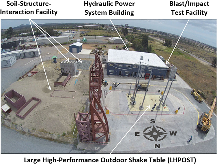
Figure 1. Englekirk Structural Engineering Center at UC San Diego.
The LHPOST is a unique outdoor shake table facility designed in 2001–2002 through a joint effort between UC San Diego and MTS Systems Corporation for the seismic testing of large systems, up to a weight of 20 MN, with a capability to accurately reproduce far- and near-field ground motions. The NSF NEES (2004–2014) and NSF NHERI (2016–present) programs have funded operations to allow the LHPOST to serve as a national shared-use research facility, enabling a wide range of landmark experiments on very large- or full-scale systems. The main research objectives of these one-of-a-kind large-scale, system level experiments have been (1) calibration, validation and improvement of analytical simulation tools to predict the seismic response of these systems, and (2) validation of the seismic performance of systems and components.
Figure 2 shows a schematic of the LHPOST mechanical and servo-hydraulic components in its 1-DOF configuration. Component 1 is the 12.2 m long by 7.6 m wide by 2.2 m deep honeycomb steel platen with a grid of multi-purpose, high-capacity, tie-down points spaced at 610 mm on center. The platen has an effective weight of 1.45 MN. Component 2 is the reinforced concrete reaction mass and the service tunnel that connects to the Hydraulic Power System Building. The reaction mass is 33.12 m long, 19.61 m wide, and extends to a depth of 5.79 m. A smaller central area of the foundation housing the hold-down struts extends to a depth of 7.92 m. The reaction mass has a weight of 43.8 MN. The unconventional (low–weight) design of the NHERI@UC San Diego reaction mass took advantage of the natural conditions at the site in terms of high soil stiffness to build a lighter and considerably less costly foundation, which resulted in a high characteristic frequency (between 11.2 and 12.5 Hz) and a large effective (radiation) damping ratio (between 32 and 42%) (Luco et al., 2011) as opposed to conventional design that relies on the use of a massive foundation to achieve a low characteristic frequency (e.g., Ogawa et al., 2001). The reaction mass also has a grid of multi-purpose, high-capacity vertical tie-downs for the deployment of safety towers, measurement frames, or reaction frames as needed for hybrid testing. Component 3 consists of the set of two ±750 mm stroke servo-controlled dynamic horizontal (longitudinal) single-ended actuators (with one actuator at each end) having a combined maximum force of 6.80 MN (1,530 kips). Each actuator is equipped with two high-flow four-stage servovalves (each rated for a flow of 10,000 liter/min (2,500 gpm) @ 7 MPa (1,000 psi) pressure drop). Thus, the two actuators together can accommodate a peak flow of 38 m3/min (10,000 gpm) which is needed to produce a platen velocity of 1.8 m/s (5.9 ft/s). Component 4 in Figure 2 consists of six vertical pressure balanced bearings (providing a hydrostatic bearing film) to support the shake table platen. In 2009, these pressure balanced bearings were upgraded with vertical actuators (equipped with pressure balanced bearings) having a stroke of ±0.127 m (±5 in). They were mounted with very small-flow 57 liter/min (15 gpm) servovalves which were controlled to balance the vertical actuator forces but did not have dynamic motion capabilities. The overturning moment resistance of the LHPOST is provided by a combination of gravity loading (test specimen plus platen) and a pair of low-stiffness vertical nitrogen gas-filled cylinders or hold-down struts (Component 5). These cylinders passively pre-compress the platen against the vertical pressure balanced bearings, work with a nitrogen pressure of 13.8 MPa (2,000 psi) corresponding to a hold-down force of 2.1 MN (470 kips) each, and have a uniaxial stroke of 2 m (79 in). Component 6 is the lateral (or yaw) restraint system (consisting of two pairs of transversal actuators, one at each longitudinal end of the platen, with each pair comprising two coupled actuators with pressure balanced bearings, one on each longitudinal side of the platen) to prevent the platen from undesirable yaw (i.e., to position the table centered) in the single axis configuration of the table. Finally, Component 7 is a weatherproofing system consisting of removable concrete covers.
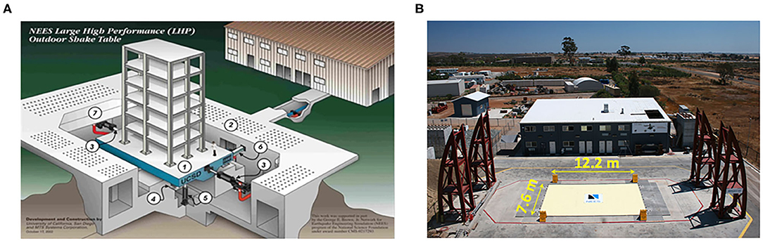
Figure 2. LHPOST in its 1-DOF configuration: (A) Schematic of mechanical and servo-hydraulic components, and (B) picture under bare table condition.
The Hydraulic Power System (see Figure 3A) consists of two pumps with a flow capacity of 720 liter/min at 21 MPa (190 gpm at 3,000 psi) and 430 liter/min at 35 MPa (114 gpm at 5,000 psi), respectively, an accumulator bank composed of 50 bottles of 190 liter each for a total accumulator volume of 9,500 liter (9.5 m3) and a maximum pressure of 35 MPa (5,000 psi), a blow-down system (with peak flow capacity of 38,000 liter/min), a 20 m3 capacity surge tank, a cooling tower and a 1.5 MW electrical power substation with a 2,500 amp transformer. During a shake table test, the hydraulic power is supplied to the actuators by the accumulator bank (charged up at 35 MPa before the test) through two blow-down valves (see Figure 3B), which convert the high-pressure oil from the accumulators (between 21 and 35 MPa) to a system pressure output of 21 MPa (3,000 psi) for controlling the actuators (through their servovalves), and through direct pumping with the 430 liter/min at 35 MPa (114 gpm at 5,000 psi) pump, which also charges the accumulator bank (before and during the test).
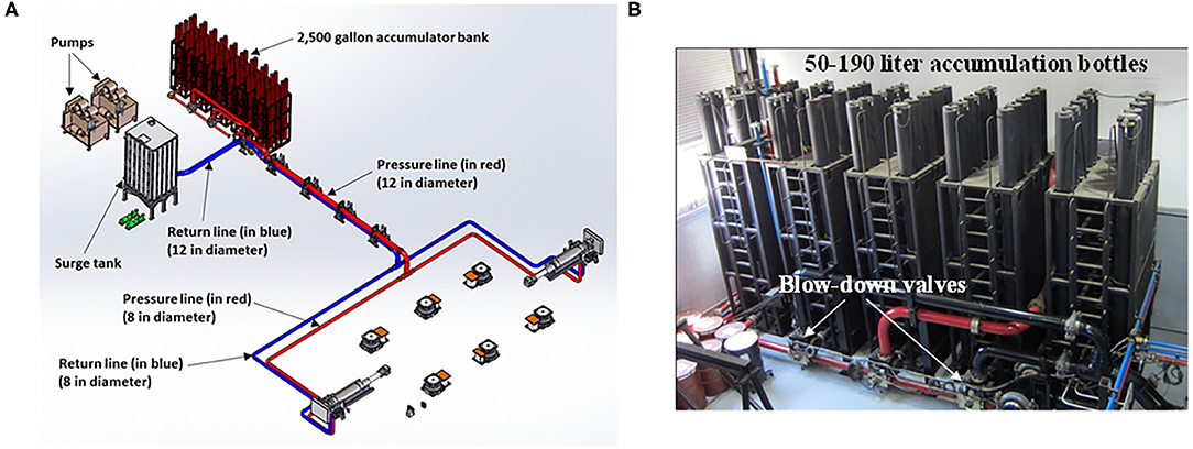
Figure 3. (A) Hydraulic power system for the 1-DOF LHPOST, and (B) accumulator bank.
The accumulator bank is composed of 50 bottles of 190 liters (50 gallons) each for a total accumulator volume of 9,500 liters (9.5 m3 or 2,500 gallons). When the hydraulic power system is turned off, each of the accumulation bottles is completely filled with nitrogen gas at 21 MPa (3,000 psi). When the accumulator bank is charged with nitrogen at 35 MPa (5,000 psi), the pressurized oil occupies approximately the bottom 20 percent of the total volume of the bottles. During a shake table test, the other pump (720 liter/min at 21 MPa) provides flow for the servovalve spools, the lateral (yaw) restraint system, and the vertical actuators. The hydraulic oil at 21 MPa (3,000 psi) is transported from the accumulator bank to the longitudinal actuators first through a 0.3 m (12 in) diameter schedule 160 steel piping (pressure line) from the accumulator bank through the service tunnel connecting the hydraulic power building to the reaction mass and then into the reaction mass through two 0.2 m (8 in) diameter steel pipes (one for each longitudinal actuator), see Figure 3A. The return flow from the actuators is directed to a 20 m3 capacity surge tank through 0.2 m (8 in) diameter steel piping (one from each longitudinal actuator) in the reaction mass and then through a single 0.3 m (12 in) diameter steel pipe from the reaction mass to the surge tank located in the hydraulic power system building. The pilot flow pressure and return lines consist of 0.05 m (2 in) diameter steel pipes.
The performance characteristics of the LHPOST in its uniaxial configuration are reported in Table 1. The overturning moment capacity of 50 MN-m can resist an effective specimen mass of 200 tons at an effective height of 10 m with an acceleration of 2.5 g. Distinguishing performance characteristics of the 1-DOF LHPOST are its peak velocity of 1.8 m/s which allows the reproduction of near-field ground motions and its maximum payload capacity of 20 MN.
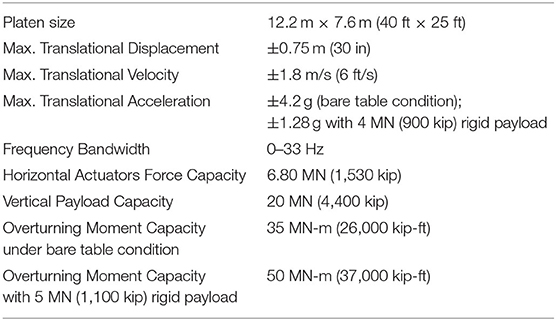
Table 1. Performance characteristics of LHPOST in its 1-DOF configuration for sinusoidal motions.
The LHPOST is controlled via an MTS 469D controller located on the first floor of the Hydraulic Power System building. An Operator Control Room resides on the second floor of the same building and houses a PC workstation directly connected to the 469D that functions as the main user interface for operations and control of the LHPOST. A second workstation serves as the Data Acquisition Central Communication Computer to interface with the National Instruments DAQ nodes used to sample the sensors deployed on the specimen tested on the shake table.
The LHPOST includes a hardware and software platform for real-time hybrid shake-table (RTHST) testing. These capabilities were verified in commissioning tests in 2017 (Vega et al., 2020). The RTHST hardware and control equipment available consist of a 500 kN, ±203 mm dynamic actuator, a four-channel MTS FlexTest controller, and a SCRAMNet ring for real-time communication and synchronization of data flow between the shake-table controller, the FlexTest controller, and Simulink Real-time Target PC. Numerical substructures can be programmed in Simulink for hard real-time implementation or in OpenSees (McKenna et al., 2020) using high performance computers capable of extending application to complex structural models. The OpenSees/OpenFresco (Schellenberg et al., 2008) open source software framework for hybrid simulation implemented in LHPOST is readily extendable to 6-DOF shake table substructure testing (Schellenberg et al., 2014).
Description of Lhpost Upgrade to 6-DOF Capability
As mentioned earlier, the LHPOST pictured in Figure 1 was conceptually designed as a 6-DOF shake table. However, it was constructed as a 1-DOF (uniaxial) system in 2002–2004 to accommodate funding available at the time. With a grant from the National Science Foundation and additional financial resources from UC San Diego, the LHPOST is being upgraded so that it can operate along all six degrees of freedom, namely the longitudinal (E-W direction or X), transverse (N-S direction or Y), and vertical (Z) translational, and roll (about the X-axis or RX), pitch (about the Y-axis or RY), and yaw (about the Z-axis or RZ) rotational motions. This is achieved by doubling the number of existing horizontal actuators and arranging them in V-shape configuration, adding a hold-down strut at the center of the table, and equipping each of the existing vertical actuators with a high-flow and high-speed servovalve. The upgrade also requires a major increase in the hydraulic power system capacity: number of pumps, accumulator bank capacity, and piping layout.
Similar to the original design of the LHPOST, the preliminary design of the LHPOST6 was developed in a collaborative effort between UC San Diego and MTS Systems Corporation. The target performance of the LHPOST6 was defined through its ability to reproduce the six tri-axial strong ground motions defined in Table 2. These ground motions are from the 1978 Tabas (Iran), 1994 Northridge (California), 1995 Kobe (Japan), 1999 Chi-Chi (Taiwan), and 2015 Nepal earthquakes, and an AC-156 compatible artificial earthquake record developed for seismic qualification testing (ICC Evaluation Services Inc., 2007).
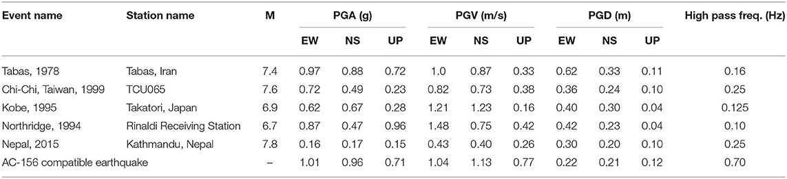
Table 2. Tri-axial strong ground motion records considered for the preliminary design of the LHPOST6.
The above design criterion requires a significant expansion of the 1-DOF LHPOST hydraulic power system. The original 9.5 m3 of accumulator banks will be upgraded to a new 36.9 m3 system of accumulator banks consisting of 75 bottles of 0.38 m3 (130 gallon) each. The expanded hydraulic power system was designed using inverse simulation. Inverse simulation uses a target tri-axial ground motion record as input and computes the system demands in terms of displacement, velocity, acceleration, force, servovalve opening, oil flow and pressure, assuming that the shake table controller can perfectly track the signal and accounting for the actual hydraulic power (accumulator banks and pumps). The inverse model takes into consideration many parameters including the equation of motion of the platen in six DOFs, the non-linear flow equations in the servovalves, as well as the dissipative forces between the platen and the vertical actuators. Inverse simulation is useful for determining (a) the physical demands for producing a desired table motion, and (b) whether a test will exceed any of the physical capacities of the system. The physical capacities of the system include actuator stroke (i.e., displacement limit), flow limits which induce velocity limits, and actuator force limits. Table 3 reports the peak demand flow rate and total demand flow required to reproduce the six considered tri-axial earthquake records in Table 2. It is observed that the Chi-Chi and Nepal earthquake records require a total flow demand exceeding 8.0 m3 (2,100 gallons), dictating the need for a new 36.9 m3 (9,750 gallon) accumulator bank, which can provide approximately 9.0 m3 (2,300 gallons) of oil at 20.7 MPa (3,000 psi).
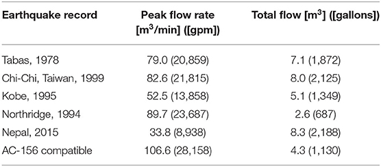
Table 3. Peak demand flow rate and total demand flow required to reproduce the tri-axial strong ground motion records defined in Table 2; bare table condition.
The ability of the LHPOST6 to reproduce tri-axial strong ground motions such as those considered in the design requires a very high flow, particularly through the large-diameter vertical actuators. As a result, each of the six existing vertical actuators will be ported with a 19 m3/min (5,000 gpm) high-flow 3-way servovalve.
The V-shaped horizontal actuator configuration is kinematically capable of producing a transverse displacement of the platen (in the N-S direction) of ± 0.94 m (±37 in) dynamically and ± 1.16 m (±45.7 in) statically (in the cushions). However, due to the geometry of the transverse cross-section consisting of the platen, reaction mass, and vertical actuators, the platen is constrained to move transversally in the range ± 0.43 m (± 17 in) as shown in Figure 4. With this new horizontal actuator configuration, it will be possible for the actuators to drive the table into an interference condition (impact between shake table platen and reaction mass or vertical actuators) in an out of control situation (e.g., loss of power) or operator programming error. There will be three lines of defense against such potential interference. The first line of defense will consist of a software limit detector (i.e., if a programmed limit is exceeded, the hydraulic system automatically shuts down). The second line of defense will consist of physical limit switches connected to a Programmable Logic Controller, which is connected to the shake table controller. A crash protection system defined later will provide the third line of defense in case of an interference. The bumpers of the crash protection system consume 0.05 m (2 in) of the available travel range in the N-S direction to dissipate the required energy in an impact condition, thus limiting the shake table travel range in the N-S direction to ± 0.38 m (±15 in).
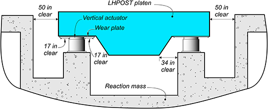
Figure 4. Displacement limit in the transverse (N-S) direction.
The uniaxial sinusoidal performance characteristics of the LHPOST6 for sinusoidal motions are shown in Table 4 for bare table condition and for the table loaded with a rigid payload of 4.9 MN (500 metric tons), respectively. The performance characteristics were determined using inverse modeling of the upgraded table system configuration.
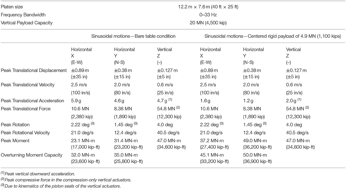
Table 4. Uniaxial performance characteristics of the LHPOST6 Sinusoidal motions—Bare table condition—Centered rigid payload of 4.9 MN (1,100 kips).
Figure 5 provides a rendering of the hydraulic power system (HPS) for the LHPOST6 design. The accumulator bank is equipped with six blow-down valves (manifolds) which convert the high-pressure oil from the accumulators (between 21 and 35 MPa) to a system pressure output of 21 MPa (3,000 psi) for supplying the system actuators. This pressure may be allowed to drop below 21 MPa near the end of a shake table test.
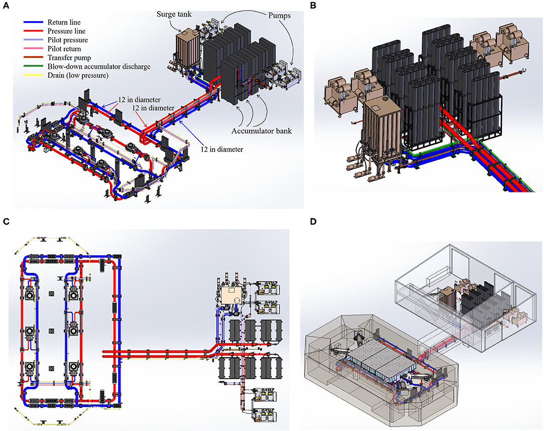
Figure 5. Hydraulic power system (HPS) the LHPOST6. (A) Isometric of HPS, (B) Primary HPS components, (C) Plan view of HPS and Piping Layout, and (D) HPS in Pump House and Reaction Mass.
For the LHPOST6, two 0.3 m (12 in) diameter pressure lines transport the high-pressure oil from the existing building to the entrance in the reaction mass, instead of one pressure line for the 1-DOF LHPOST, see Figures 3A, 5. In the reaction mass, these two pressure lines feed a “pressure” ring main (0.3 m diameter single steel pipe) that goes around the inside of the reaction mass passing through and feeding the servovalves of all the horizontal and vertical actuators as shown in Figures 5A,C (red colored piping in the figure images). The return flow from all the horizontal and vertical actuators is directed to the surge tank through a “return” ring main that goes around the inside of the reaction mass and then through two 0.3 m (12 in) diameter steel tubes that cross the tunnel between the reaction mass and the hydraulic power system building as shown in Figure 5 (blue colored piping in the figure images). The 0.05 m (2 in) diameter pilot flow pressure and return lines for the 1-DOF LHPOST will be extended accordingly and replaced with 0.075 m (3 in) diameter steel piping. The existing surge tank capacity (20 m3 or 5,280 gallon) is sufficient for the 6-DOF upgrade. As mentioned previously, the upgrade also requires the doubling of the pumps, i.e., one 720 liter/min at 21 MPa (190 gpm at 3,000 psi) pump to provide pilot flow to the servovalves of all actuators for servo-control, and three 430 liter/min at 35 MPa (114 gpm at 5,000 psi) pumps to pressurize (charge) the accumulator banks (see Figure 5) before and during a shake table test, as well as a new transfer pump for each of the two new pumps. The electrical power substation must be upgraded to 2.5 MW with a 3,000 amp transformer to support the power requirement of the LHPOST6. Figure 6 shows the 19 m3/min (5,000 gpm) high-flow 3-way servovalve, which will be added to each of the six vertical actuators in order to provide the very high flow required to reproduce tri-axial strong ground motions such as those considered in the upgrade design (see Table 2). The additional hold-down strut at the center of the platen required by the upgrade can be seen in Figure 6C. It is identical to the other two hold-down struts used for the LHPOST.

Figure 6. High-flow servovalves for vertical actuators: (A) servovalve-actuator pair, (B) connection of servovalve to pressure (red) and return (blue) pipes, and (C) longitudinal cut through the reaction mass longitudinal axis.
The LHPOST6 required a redesign of the cover plate system comprising of twenty steel plates (19 mm thick) supported on high-speed castor wheels and hinges, corner tubes, and concrete planks. The cover plate system provides physical protection to the servo-hydraulic system in the reaction mass from falling debris and objects. The cover plate system also offers a degree of protection against the elements and prevent wild animals from falling into the reaction mass pit. The cover plate system must satisfy many physical constraints while accommodating multi-DOF movements of the platen. Figure 7A depicts the cover plates with the platen at the rest position. At the corners, the plates are connected via a series of telescopic tubes, see Figure 7B. Several removable rubber membranes in the form of fish scales will be placed on top of the tubes and the edges of the steel plates. These membranes will be removed during shake table testing to provide adequate ventilation to the reaction mass pit.
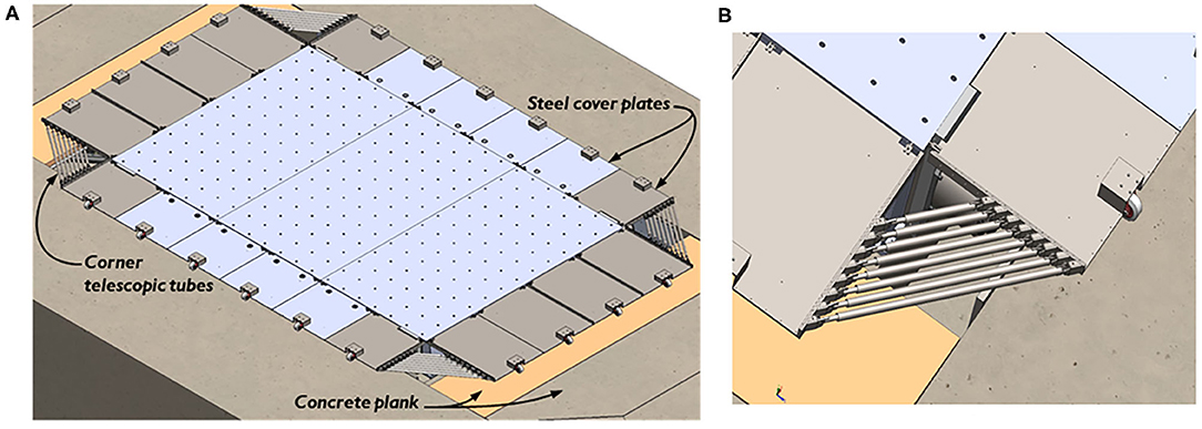
Figure 7. View and rendering of the cover plate system: (A) steel plates locations in the at rest position, and (B) steel plates and telescopic tubes at the corners.
Crash Protection System
The objective of the crash protection system is to prevent or minimize damage to the shake table system or reaction mass from an uncontrolled motion condition (impact hazard) due to a loss of power or operator programming error which are not caught properly by the first two lines of defense (software limit detector and physical limit switches). The crash protection system consists of four energy dissipation devices (bumpers) mounted near the four corners of the platen through heavy steel plates bolted to the top and bottom plates of the platen as shown in Figure 8. The main design criterion for the crash protection system is to absorb the kinetic energy of a specimen mass of 10 MN (1,000 ton), in addition to the platen mass of 1.75 MN (178 ton), moving at 1 m/s into the bumpers (including the actuator driving force) and dissipate this energy over a bumper travel of 0.05 m (2 in). For two bumpers (per side of the platen), this results in a force of 10 MN per bumper. In each bumper, the compressive impact force is transferred into 42 tensile rods of highly ductile stainless steel (see Figures 8A,B) engaging into a plastic tensile yielding behavior at near-constant force. After an impact, the yielded tensile members would be replaced. A detailed non-linear finite element analysis of the reinforced concrete reaction mass was performed and showed that an impact force of 10 MN will be resisted with very small displacements and deformations (fractions of a mm) of the reaction mass.
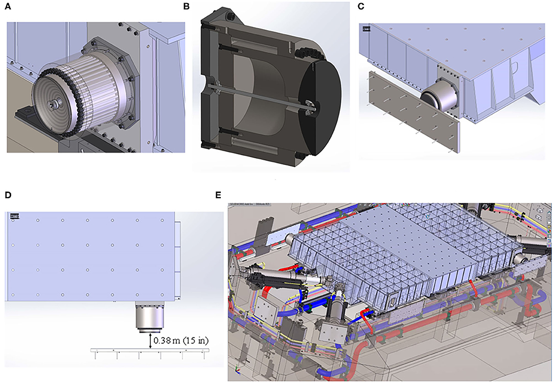
Figure 8. Crash protection system: (A) view of 42 tensile rods, (B) internals of crash protection device, (C) crash protection device and impact plate, (D) distance between crash protection devices and impact plates, and (E) overall view of shake table platen and two of the crash protection devices.
Horizontal Actuators
The two new horizontal actuators will have the same functionality and performance capabilities as the two horizontal actuators for the 1-DOF LHPOST. The new actuators will have different manifold configurations to support the operation of the system in the 6-DOF mode. The existing two horizontal actuators will also be equipped with the new manifold configurations. Figure 9 shows several views of the LHPOST6 with its horizontal actuators in V-shape configuration within the reaction mass.
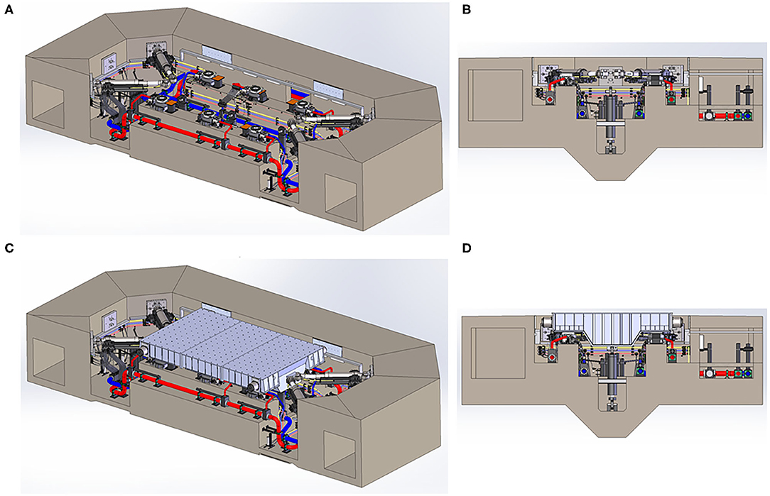
Figure 9. Overall design configuration of the LHPOST6: (A) horizontal actuators in V-shape configuration, vertical actuators and pedestals to park the platen, (B) transverse view with horizontal actuators and hold-down struts, (C) horizontal actuators connected to shake table platen equipped with crash protection devices, and (D) transverse view with shake table platen equipped with crash protection devices.
LHPOST6 Controller
The existing MTS 469D Seismic System Controller used on the 1-DOF LHPOST will be completely replaced with MTS' latest electronics and control software. The new MTS 469D controller will provide for simpler shake table tuning, system operation, and test execution. It will permit faster set up and more “tools” to handle difficult (e.g., non-linear degrading) specimens. The control software provides an advanced graphical user interface (GUI) with full functionality provided for system tuning, test set up and operation, table data acquisition, and advanced high-level adaptive control for high fidelity earthquake waveform reproduction. It also includes a set of high level fixed control techniques such as: (i) Degree of Freedom Control (DOF), (ii) Three Variable Control (TVC), (iii) Delta Pressure Stabilization (DPS), (iv) Adaptive Control Techniques (e.g., Adaptive Inverse Control—AIC), (v) EZ Tune (automatic tuning wizard for AIC), and (vi) Safe Abort, as well as tools for Off-Line Iterative (OLI) Compensation. The Safe Abort option allows a test to be interrupted with a very quick smoothly damped trajectory to a safe position without causing abrupt system motion which can damage the specimen. This Safe Abort, like all MTS safety limits, can be triggered by system limit detectors, or operator intervention. The new MTS 469D controller will be customized for the characteristics of the LHPOST6. The two existing table feedback uniaxial accelerometers will be replaced with a set of eleven uniaxial feedback accelerometers (3 E-W, 3 N-S, and 5 vertical) to control all six degrees of freedom of the LHPOST6.
The TVC portion of the 6-DOF 469D controller is exactly the same for each of the six DOFs and the same as for the 1-DOF LHPOST. There are six control channels, one for each DOF, and the controller for each DOF takes only feedback associated with that DOF (i.e., the TVC does not mix DOF feedbacks between the SDOF controllers). The controller uses back-and-forth transformations from Cartesian DOFs to actuator DOFs (from Cartesian space to actuator space). The dynamic cross-coupling between DOFs is mitigated by Adaptive Inverse Control (AIC) and Off-Line Iterative (OLI) Compensation, which take care of the diagonal and off-diagonal terms of the 6 × 6 total shake table transfer function matrix. The load balancing control algorithm for the LHPOST6 remains the same as for the 1-DOF LHPOST. The only difference is that the vertical actuators have dynamic capabilities (i.e., are capable of more velocity) in the LHPOST6.
Performance Simulation of LHPOST6
The design of the LHPOST6 was modeled using inverse simulation and was then validated using forward simulation. The forward model of the LHPOST6 includes the rigid body dynamics in 6-DOFs of both the platen and a rigid specimen, servovalve and actuator dynamics (with non-linear flow equations), accumulator banks and line accumulators, and a virtual replica of the MTS 469D controller that will be installed on the LHPOST6 (Thoen, 2019). In the forward model, the controller was tuned for the characteristics of the LHPOST6 design using the new 469D Auto-Tuner capability. The tuned closed-loop forward model provides the ability to perform “dry runs” of the LHPOST6 system and thus evaluate, pre-construction, its signal tracking performance capability. After completion of the LHPOST upgrade, the forward model will also allow for offline tuning based on the test specimen characteristics and will be very useful for safe offline operator training (i.e., shake table simulator). Figure 10A compares the target (or desired) and simulated achieved translational acceleration time histories of the shake table, and Figure 10B compares the target and achieved five-percent damped tri-partite (displacement/pseudo-velocity/pseudo-acceleration) linear elastic response spectra for the three components of the 1994 Northridge earthquake record (refer to Table 2). Similar levels of signal tracking fidelity were observed for the other strong tri-axial earthquake records considered for the upgrade design. These comparisons show a good signal tracking capability of the LHPOST6 design. This is especially true for the vertical ground motion components, given the fact that the vertical actuators of the LHPOST are single-acting, i.e., they can only push (upwards) and cannot pull (downwards) the platen since they have zero retraction force. The nitrogen-filled hold-down struts pull the platen down but without closed-loop dynamic capabilities. The level of fidelity in signal reproduction for the vertical component and other motion components can also be further improved through the advanced control capabilities built in the MTS 469D controller such as Adaptive Inverse Control (AIC), On-Line Iteration (OLI) and Specimen Dynamics Compensation (SDC) (Thoen et al., 2012).
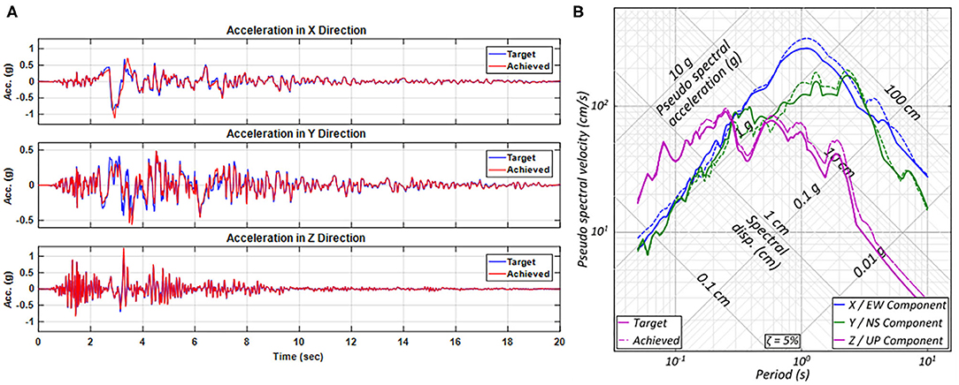
Figure 10. Comparison of target and (simulated) achieved tri-axial 1994 Northridge earthquake record (see Table 2): (A) acceleration time histories, and (B) 5% damped tri-partite linear elastic response spectra.
A simple mechanical model of the rigid platen supported by the oil column springs of the 4 horizontal and 6 vertical actuators results in the oil column frequencies and modes reported in Table 5. The frequency of the oil column mode in the longitudinal (E-W) direction of the 1-DOF configuration of the LHPOST is approximately 10.6 Hz. The three lowest oil column frequencies of the LHPOST6 are 7.4, 8.9, and 9.3 Hz in the transverse, yaw, and longitudinal directions, respectively. As for the 1-DOF LHPOST, the resonant peaks of the oil column modes will be damped out numerically by the shake table controller using the delta-pressure feedback gains and adjusting the notch filters' parameters.
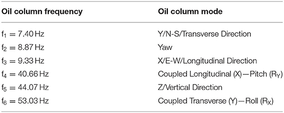
Table 5. Prediction of oil column frequencies and modes for the LHPOST6 (bare table).
Instrumentation of Test Specimens and Data Acquisition System
Experiments conducted on the LHPOST typically require fifty to six-hundred sensor measurement channels. The NHERI LHPOST facility has a large inventory of sensors available to instrument test specimens. These sensors and their quantities include: (i) MEMS-based accelerometers (205), (ii) Linear displacement transducers (142), (iii) String potentiometer displacement transducers (119), (iv) Load jacks (4), (v) Load cells (31), (vi) Soil pressure transducers (32), and (vii) GPS System with RTD_NET Software by Geodetics with 3 receivers operating at 50 Hz to measure translational motions in 3D with a precision of 1.5 mm. Strain gauges are used extensively but are considered disposable instrumentation. The site also has an array of 1080 and 4K high definition (HD) video cameras running at 30 frames per second (fps) that are fully synchronized with the sensors: GoPros 4K (15), Axis 240Q/241Q video servers streaming (4), IQeye streaming/time-lapse video (3).
The LHPOST6 facility will be equipped with a new data acquisition (DAQ) system consisting of 12 nodes with 64 channels each (for a total of 768 measurement channels) at 24-bit Analog-to-Digital resolution, simultaneous sampling, and a sampling rate up to 25.6 kS/s per channel. This DAQ will provide superior aliasing rejection with user-configurable digital anti-aliasing filters, and zero skew time between different channels due to simultaneous sampling, thus enabling accurate recordings from very small (ambient vibrations) to very large (seismic testing) motions.
The site is open to explore the use of new measurement/sensor technologies such as Digital Image Correlation techniques to measure the motion and deformation of test specimens. However, the site's top priority is to provide highly reliable measurements and high-quality data to the researchers and/or commercial clients. Research teams using the site are also encouraged to deploy payload projects exploring innovative sensing technologies (e.g., low-power wireless sensors).
The site also has calibration equipment for sensors and data acquisition systems, as required for its ISO/IEC Standard 17025:2005 accreditation. The NHERI@UC San Diego Experimental Facility also has a fully configured, end-to-end, live video streaming production system with high resolution and low latency. NHERI@UC San Diego is on social media (youtube, facebook, twitter).
Past Experiments Conducted on the LHPOST and IMPACTS
Since the LHPOST commissioning on October 1, 2004, and until its closure on October 1, 2019 for the 6-DOF upgrade, 34 major research and commercial projects were conducted on the LHPOST during its life as a national shared-use NSF-NEES and NHERI equipment facility. The following is the list of specimens tested, in chronological order, on the LHPOST from 2004 to 2019, with the scale of the specimen and a picture of each of them provided in Figure 11: (1) seven story structural wall building slice (full-scale) (Panagiotou et al., 2011); (2) seismic base isolator (miniature scale); (3) bridge abutment and soil embankment inside large laminar soil box (scale: distorted); (4) new type masonry building structure and masonry veneer—Phase 1 (full-scale); (5) precast concrete building with deformable diaphragms and re-centering post-tensioned RC walls (scale: 0.40) (Belleri et al., 2014); (6) non-ductile RC frames with infill walls—Phase 1 (full-scale) (Billington et al., 2009); (7) new type masonry structure and masonry veneer—Phase 2 (full-scale); (8) non-ductile RC frames with infill walls—Phase 2 (full-scale); (9) retaining wall with and without sound wall inside large laminar soil box (scale: distorted) (Mock and Cheng, 2015); (10) 65-kW steel wind turbine (full-scale) (Prowell et al., 2011); (11) industrial-type metal building (full-scale) (Uang et al., 2011); (12) RC bridge pier (full-scale) (Schoettler et al., 2009); (13) reinforced masonry wall building (full-scale) (Stavridis et al., 2016); (14) five story dual wall-frame RC building with non-structural components and systems (full-scale) or BNCS project (Chen et al., 2016; Pantoli et al., 2016a); (15) reinforced masonry wall building (full-scale); (16) geogrid reinforced soil retaining wall inside large stiff soil confinement box (full-scale); (17) RC bridge columns supported on rocking shallow foundations (scale: 0.333) (Antonellis et al., 2015); (18) four story woodframe building with soft bottom story (full-scale) (Bahmani et al., 2017); (19) four story RC building with inertial force-limiting floor anchorage system (scale: 0.4) (Zhang et al., 2018); (20) partially grouted reinforced masonry building (full-scale); (21) seismically isolated unibody residential building (full-scale); (22) 500kV bus support structure with retrofit added to the base of the pylons (full-scale); (23) cut-and-cover shallow tunnel embedded in soil inside large laminar soil box (scale: 0.111) (Kim and Elgamal, 2017a); (24) helical piles embedded in soil inside large laminar soil box (full-scale) (ElSawy et al., 2018); (25) spillway retaining wall embedded in soil inside large laminar soil box (distorted scale) (Kim and Elgamal, 2017b); (26) six story light-gauge cold-formed steel framed building subjected to seismic and fire tests (full-scale) (Wang et al., 2015b); (27) electrical relay racks (full-scale); (28) seismic isolated RC slabs for hybrid shake table commissioning tests (scale: 0.25) (Vega et al., 2020); (29) two-story cross-laminated (heavy) timber building with re-centering (rocking) post-tensioned walls (full-scale) (Pei et al., 2019); (30) pile foundation in multi-layer saturated soil strata inside the large laminar soil box (distorted scale); (31) shear-dominated reinforced masonry wall system—Phase 1 (full-scale); (32) repetitively framed mid-rise cold-formed steel building (full-scale); (33) shear-dominated reinforced masonry wall system—Phase 2 (full-scale); (34) steel building with seismic collectors (scale: 0.5). The geo-structures require the shake table to be used in combination with one of the two large soil boxes available at ESEC: (1) a steel laminar soil shear box of dimensions 6.7 m (L) × 3.0 m (W) × 4.7 m (H), and (2) a composite steel-concrete stiff soil confinement box of dimensions 10.0 m (L) × 4.6 m or 5.8 m (W) × 7.6 m (H) (Fox et al., 2015).
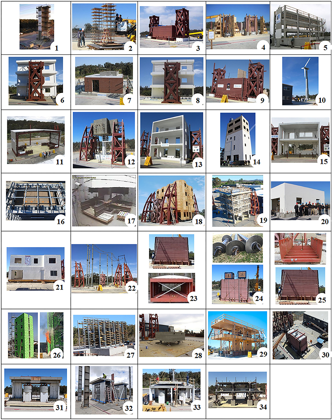
Figure 11. Specimens tested on the LHPOST in the period 2004–2019.
Most tests performed on the LHPOST are landmark tests. The seven-story structural wall building slice (see insert 1 in Figure 11) and reinforced concrete bridge pier (see insert 12 in Figure 11), which were densely instrumented and tested to the brink of collapse, provided the community with a unique dataset. Blind predictions were organized for these two tests, and the predictions provided a unique opportunity to look into model uncertainty and human error (Restrepo, 2007; Terzic et al., 2015).
The three-story precast concrete building (see insert 5 in Figure 11) was a capstone of the multi-university (University of Arizona, Lehigh University, and UC San Diego) Diaphragm Seismic Design Methodology (DSDM) research project jointly funded by the Precast/Prestressed Concrete Institute (PCI) and NSF with outstanding industry support and input. Three different types of precast concrete diaphragms were incorporated into this building. Because the test program included many (sixteen) design earthquake tests, a pair low-damage re-centering precast post-tensioned concrete walls were used to provide lateral load resistance to the building. The DSDM project was extremely successful and culminated with the inclusion of floor acceleration provisions for precast building diaphragms and other systems in the ASCE 7–16 standard.
The large-scale tests conducted on masonry structures with the LHPOST facility represent major masonry research efforts in the US to advance the seismic performance assessment and design of existing as well as new masonry construction. In particular, data from the masonry-infilled non-ductile reinforced concrete frame study (see inserts 6 and 8 in Figure 11) led to improved performance assessment methods that have been adopted into ASCE 41–17. Data from the studies of reinforced masonry (see inserts 13, 15, and 20 in Figure 11) contributed to the development of new shear-friction design provisions in TMS 402–16, and led to the development of improve load-displacement backbone curves for masonry walls, which are being implemented in ASCE 41. Data from the building system tests (see inserts 15, 31, and 33 in Figure 11) provided new insight into the displacement capacity of masonry buildings and has been used to validate detailed as well as simplified numerical models that were used to solve the short-period building performance paradox in the ATC 116 project.
The BNCS project (see insert 14 in Figure 11) enabled, for the first time, the full-scale experimental investigation of a wide range of functioning non-structural components when installed in a system setting. Subjected to service, design and maximum credible earthquake scenarios, the various NCSs in this total building specimen were allowed to interact with the structural system as well as with other NCSs. Vertical and horizontal spanning NCSs were installed within the test building, using seismic and non-seismic compliant detailing. Findings from these tests demonstrate the efficacy of building base isolation, as the building and its NCSs were undamaged and the system suffered no loss of functionality. Under fixed base condition, the BNCS building earthquake test results also facilitated advancements to design and practice provisions within ASCE 7 (ASCE/SEI, 2016), including provisions for ductile corner connections for precast concrete facades (Pantoli et al., 2016b), higher importance factors for stairs (Wang et al., 2015a), and improved boundary condition detailing for elevators (Wang et al., 2016), to name a few important impacts.
The data, information and knowledge gained from the experiments conducted on the LHPOST have greatly advanced analysis and design tools, design guidelines and codes, design practice, and seismic response predictive capabilities for buildings (old and new), bridges, critical facilities, non-structural components and systems, wind turbines, geo-structures and foundation systems, leading to improved earthquake safety in the community overall. Moreover, the full-scale dynamic testing capability provided by the LHPOST has enabled new and innovative low-damage earthquake protective systems to be tested and incorporated into practice. Indeed, the ability to test full size structures has made it possible to physically validate the seismic performance of many systems that previously could only be assessed with computer models or using small-scale physical models. However, with the limitation of the LHPOST in its 1-DOF configuration, important aspects of seismic response for many problems in earthquake engineering and application scenarios could not be investigated. Currently, the only large-capacity 6-DOF shake table capable of performing such tests is the E-Defense facility in Japan (Nakashima et al., 2018). The only shake table in the world that has a larger payload capacity than the E-Defense table is the LHPOST. Existing moderate to large scale 6-DOF shake tables in the U.S. at the University of California at Berkeley (0.70 MN payload), University at Buffalo (2 × 0.45 MN payload), and University of Nevada Reno (0.45 MN payload) have contributed toward understanding the multi-component seismic response of equipment, building and bridges, albeit at reduced scale for large structural systems. The multiple tables at Buffalo and Reno (when paired with three additional bi-directional tables) have supported landmark testing of long-span bridge structures.
Future Research Enabled by the LHPOST6
The LHPOST6 will enable ground-breaking experimental research in earthquake engineering related to structural, geo-structural, soil-foundation-structural, and non-structural components and systems, including how these systems behave during realistic multi-component earthquake excitations, and how they should be conceived and designed to resist such excitations best. A select set of important research areas and studies that will be made possible by the LHPOST6 are described in the following sections.
Building Structures
One of the largest and diverse areas of research is in low-rise, mid-rise, or high-rise buildings made out of a variety of materials such as structural steel, cold-formed steel, reinforced/prestressed/precast concrete, high-performance concrete, wood-frame, cross-laminated (heavy) timber, unreinforced and reinforced masonry, and advanced materials. Topics also include the seismic performance of total building systems, those designed with super columns or outriggers, and special issues such as floor vibration isolation.
Masonry Components and Systems
Unreinforced Masonry (URM) buildings have suffered severe damage or collapse in past earthquakes. The failure of an URM building in a seismic event has often been characterized by the out-of-plane collapse of the walls (Felice and Giannini, 2001). The resistance of an URM wall to out-of-plane forces relies on arching action, which could be weakened by damage caused by in-plane forces. As a result, bi-axial horizontal ground motions are particularly damaging to an URM building, and URM walls subjected to uniaxial in-plane forces have been reported to exhibit significantly better performance compared with bi-axial loading conditions. Furthermore, the vertical ground acceleration could change the axial load on a wall and thus its in-plane and out-of-plane shear resistance, while also affecting the arching mechanism and stability of the wall. The LHPOST6 will enable the robust assessment of the seismic safety of URM buildings and the development of effective retrofit and strengthening methods.
Steel Systems
There has been extensive research on the seismic performance of hot-rolled structural steel and cold-formed steel systems in the areas of structural stability and progressive collapse mitigation, connection behavior, and seismic risk and life-cycle cost quantification (Stojadinović et al., 2000; Khandelwal et al., 2008). However, additional research is needed to assess interactions in building systems undergoing earthquakes, e.g., competing inelasticity in vertical and horizontal lateral-force resisting systems, overstrength and system effects derived from the participation of gravity and non-structural framing in lateral response (e.g., Imanpour et al., 2016; Peterman et al., 2016; Cravero et al., 2020).
Structural Concrete Systems
Structural concrete has been a prevailing construction material for low, high-rise, and super-tall buildings. However, most research supporting seismic design with structural concrete has been limited to components (e.g., Kurama et al., 1999; Lehman et al., 2004; Naish et al., 2013; Tazarv and Saiid Saiidi, 2016) or reduced-scale models of building systems (e.g., Rodriguez et al., 1995). In the US, only three landmark building tests were performed at large- or full-scale on a shaking table (Schoettler et al., 2009; Chen et al., 2016; Zhang et al., 2018) but under single-axis excitation. Therefore, research is needed on innovative, resilient, seismic-resistant concrete systems under multi-axial excitation, specifically to improve modeling and analysis capabilities for component and system behavior. Of particular interest are the use of high strength materials (reinforcing bars and concrete) and advanced materials for seismic civil applications, special concrete moment frames, and structural walls including the combination of dual systems, precast concrete frame, and wall structures, and sustainable reinforced concrete structures utilizing recycled materials. Of great interest, and somewhat neglected in research, is the evaluation of the seismic performance of commercial tilt-up buildings. Many such buildings behaved poorly during the 1994 Northridge earthquake (Mitchell et al., 1995), which prompted the need to revisit various diaphragm-to-wall connection methods. Recent research indicates that some of these structures may still be quite earthquake vulnerable (Koliou et al., 2016). The LHPOST6 will benefit the above research areas by providing the opportunity to conduct large-scale multi-axial shake table tests of complete buildings and structures of complex geometries.
Current seismic design standards, such as (ACI, 2014; AISC, 2016; ASCE/SEI, 2016, 2017; TMS, 2016) are largely based on data obtained from quasi-static testing of structural components, most of which were conducted with in-plane horizontal loading. While such data are crucial for the development of design and detailing requirements to ensure the ductile behavior of structural members, how a building will perform in an earthquake is also highly dependent on how these components are proportioned, connected, and interact with each other as a system. Without due consideration of the system's behavior in design, the actual seismic response and load-resisting mechanism of a building could differ significantly from what is anticipated by current design standards. Current design standards also rely on 3D computational models of structures to extrapolate results of uniaxial shake table tests to project structural performance under multi-axial loading conditions. The lack of pertinent data to validate the accuracy of computational models for these predictive analyses is an important issue. Multi-axis shaking-table tests are needed to study more realistically the behavior of civil structures and to improve current seismic design methods and standards.
Non-structural Components and Systems (NCSs)
NCSs, generally categorized as architectural, mechanical, electrical, and plumbing, or building contents, are elements that facilitate operation of a building. Importantly, they typically comprise 75–85% of the construction cost of commercial buildings (Miranda and Taghavi, 2003). NCSs have suffered significant damage, led to appreciable losses, and endangered occupants during past earthquakes (Federal Emergency Management Agency FEMA E-74, 2012). Significant efforts have been undertaken to develop simplified design procedures to account for the range of practical NCSs configurations, and the limitations are well-known (Filiatrault and Sullivan, 2014). The scarceness of full-scale building shake table tests that incorporate NCSs limits our understanding of the seismic response of these non-structural components. For example, the landmark NSF-funded Building Non-structural Components and Systems (BNCS) test program (refer to #14 in Figure 10, Pantoli et al., 2016a) incorporated a complete suite of NCSs, including operable egress (stairs and elevators), facades (precast concrete and light-weight cold-formed steel), and interior equipment and architectural support contents (ceilings, HVAC, piping, etc.). This project focused on the “total building” and, in particular, the interactions between components (non-structural-to-non-structural and structural-to-non-structural) and offered new insight into understanding the seismic response of a wide range of NCSs, but the tests were carried out under single-axis ground motions. This test program would have immensely benefited from the upcoming capability of the LHPOST6. NCSs are by their nature secondary systems; their response depends upon the response of the supporting primary system, in most cases a building. The varying vibratory response of a building under multi-directional input motion will then naturally affect the input motion to the NCSs. Important to enveloping a building, the wide range of architectural facades have a high degree of variability in their connectivity to the supporting structure, and thus their response to multi-axis input requires understanding (Pantoli et al., 2016b). Limited recent tests, supported by field observations, demonstrate the importance of advancing our understanding and predictive capabilities under multi-directional loading of NCSs in building systems. Full-scale multi-axial shake table tests are needed to advance the development of a reliable, unified design strategy for NCSs accounting for multi-directional earthquake excitation.
Advanced/Innovative Earthquake Protective Systems
Extensive damage in conventional buildings have caused a push in earthquake affected communities in the past two decades to use low-damage structural earthquake protective systems. Such systems can sustain significant non-linear response, large lateral displacements, and damping with practically no damage and maintained operability after strong earthquake ground motions. This is currently a very active research area that includes base isolation, rocking foundations and systems, self-centering systems, inertial force-limiting floor anchorage systems, dampers, buckling-restrained braces, and new materials (Ozbulut et al., 2011; Belleri et al., 2014; Bahmani et al., 2017; Pei et al., 2019).
Many structures have survived strong earthquakes unscathed, courtesy of rocking of the foundation (Housner, 1963). In competent soils not susceptible to liquefaction, rocking can be used as a mechanism that concentrates the non-linear response and provides energy dissipation in some structures. This aspect has been widely demonstrated in centrifuge, field, and 1-g shake table testing (e.g., Deng and Kutter, 2012; Gelagoti et al., 2012; Pecker et al., 2014). At the LHPOST facility, Antonellis et al. (2015) carried out shake-table testing of two 1:3 scale bridge piers with shallow foundations designed to rock (refer to #17 in Figure 10). The test specimens were placed inside the large stiff soil confinement box described in Fox et al. (2015), which was partially filled with poorly graded medium sand and water. Because of the uni-directional limitation of the LHPOST, one of the test units was aligned with the direction of the excitation, whereas the other was rotated 30 degrees. While this promoted multi-directional input to the specimen, the two horizontal translational input motions were fully correlated. The LHPOST6 used in combination with a large soil box will enable more realistic investigation of earthquake protective systems of all types at large or full-scale, including passive, semi-active, and active seismic response modification devices such as dampers, low-cost unbonded fiber-reinforced elastomeric bearings, and buckling-restrained braces, as well as new electroactive and electromagnetic materials and shape memory alloys (Ozbulut et al., 2011).
Dynamic Soil-Structure Interaction (SSI)
The LHPOST6 is ideally suited for experimental investigations of dynamic SSI. The kinematic interaction of the foundation with the soil (in the absence of the superstructure) under internal seismic wave excitation leads to translational and rotational components of foundation input motion. This occurs for embedded foundations for all types of elastic wave excitation and for surface foundation subjected to non-vertically incident waves and to spatially random ground motions. When a superstructure is present, the inertial interaction results in additional rocking components of motion of the foundation and additional torsional components, particularly, when the structure is not symmetrical. Thus, even when it can be assumed that the foundation is sufficiently rigid, the motion of the foundation will have at least 6-DOFs, including translational and rotational components of motion (e.g., Luco, 1980; Roesset, 1980). The following three general types of experimental SSI studies can be envisioned with the LHPOST6:
Verification Studies Under Tri-axial Excitation
Computer models of the complete soil, foundation, structure system can be used to obtain the total translational and rotational motion of the foundation, which can then be applied at the base of the structure placed on the LHPOST6. The resulting experimental motion of the structure can be compared with the numerical simulation to validate both the theoretical model and computational method. Independent of the validation justification, the response of structures to simultaneous translational and rotational motions is of interest for research aimed at representing the free-field ground motion as consisting of both translational and rotational components, extending the current practice of including only translational components (in the absence of SSI) (Lee and Trifunac, 1985, 1987).
Hybrid Tests
In these ambitious tests, the soil will be modeled in the computer, and the foundation input motion (i.e., the response of the foundation to seismic waves) computed numerically; the compliance matrix (i.e., used to compute the response of the “foundation and soil” to external forces from the superstructure) will be computed numerically as well. In the test, the total foundation motion will be applied (through the shake table platen) at the base of the structure placed on the shake table and the force that the structure exerts on the platen will be obtained from the motion of the structure thus closing the loop. These tests could be used to study the non-linear seismic response of structures in the presence of soil-structure interaction, as well as studies of the torsional response of structures.
Large Soil Box Tests Under Tri-axial Excitation
In these tests, scaled models of structures will be supported on soils placed in one of the large soil boxes available. The soil box will be subjected to tri-axial base motions to better simulate the seismic excitation. These tests could be used to study the non-linear response of soils, the response of partially saturated soils, and the non-linear interaction of foundations, structures, and the soil. The contribution of radiation damping into the soil to the apparent damping in the structure could also be studied in this fashion. The effects of the coupling through the soil on the seismic response of adjacent structures, a topic of importance in the urban environment and in farms of storage tanks and wind turbines, could also be investigated through this approach.
Geostructures
Soil Foundation Structure Interaction (SFSI) can be beneficial or detrimental to the performance of structures during earthquakes. Design guidelines considering these effects are mostly based on analytical models, computational simulations, small-scale shake-table experiments in centrifuges, large-scale field testing of pile and slab foundations, and field observations from past earthquake events. Large-scale field testing provides pertinent data to calibrate soil properties in analytical and computational models; however, it cannot conclusively validate how SFSI affects structural response during an earthquake because these tests neglect the dynamics of soil response and the inertial interaction with the superstructure. Moreover, they are generally at amplitudes lower than design target earthquake demands. The scale of SFS specimens in centrifuge tests must be necessarily very small. This means that detailing of superstructure elements and materials for these tests necessitates simplicity due to the small scale. Therefore, the results of such tests will have limited accuracy regarding the behavior of the actual structure or foundation. Shake-table tests used in combination with large soil boxes with reasonable size foundation and structural models are needed to complement centrifuge tests to validate corresponding computational models. These types of tests can also be used to study the performance of underground structures (such as energy vaults, pipelines, and deep and shallow tunnels), bridge abutments, earth retaining walls, levees, embankments, large cut and fills, and slope stability in hillside construction. The LHPOST6 can support the testing of underground pipelines subject to liquefaction loads or fault crossing demands by taking advantage of the large displacement capacity of the LHPOST6, enabling researchers to conduct large-scale dynamic testing of underground facilities and pipelines and techniques for evaluating ground movement patterns and stability for a variety of excavation, tunneling, micro-tunneling, and mining conditions (O'Rourke et al., 2008).
Summary and Conclusions
The Natural Hazards Engineering Research Infrastructure (NHERI) UC San Diego Large High-Performance Outdoor Shake Table (LHPOST) Experimental Facility and its capabilities under its past 1-DOF configuration (LHPOST) and future 6-DOF configuration (LHPOST6) were described. The LHPOST is a national shared-use facility supported by the National Science Foundation and available to researchers to conduct research in earthquake engineering and seismic hazard mitigation. The LHPOST is the largest facility of its kind in the US for conducting earthquake engineering research. It has the largest payload capacity in the world (20MN) and ranks second in size after Japan's E-Defense shake table. The tallest structures ever tested on a shake table have used the LHPOST, which is free from height restrictions.
The vision for the NHERI@UC San Diego Shake Table Experimental Facility is rooted on three critical needs for advancing the science, technology, and practice in earthquake disaster mitigation and prevention: (1) fundamental knowledge for understanding the system-level behavior of buildings (including non-structural components and systems), critical facilities (e.g., energy structures), bridges, and geo-structures during earthquakes, from the initiation of damage to the onset of collapse; (2) Experimental data to support the development, calibration and validation of high-fidelity physics-based computational models of structural/geotechnical/soil-foundation-structural systems that will progressively shift the current reliance on physical testing to model-based simulation for the seismic design and performance assessment of civil infrastructure systems; and (3) Proof of concept, benchmark and validation/verification tests for seismic retrofit methods, protective systems, and the use of new materials, manufacturing methods, components, systems, and construction methods that can protect civil infrastructure systems against earthquakes.
The LHPOST was conceptually designed as a 6-DOF shake table. However, it was constructed as a 1-DOF system in the period 2002–2004 to accommodate funding available at the time. Since its commissioning on October 1, 2004, 34 landmark research and commercial projects have been conducted on the LHPOST, contributing to advancing our understanding of the seismic response behavior of civil infrastructure systems, improving design codes and standards, validating high-fidelity 3D computational models, and developing accurate decision-making tools necessary to build and maintain sustainable and disaster-resilient communities. Some of these research projects were briefly described in this paper. All test results and research data are shared through the NHERI Data Depot repository at NHERI DesignSafe (https://www.designsafe-ci.org/data/browser/public/).
The LHPOST6 is currently being built and is scheduled to reopen for operations in fall 2021. Once upgraded, the LHPOST will be able to reproduce all six components of ground motion experienced during earthquakes, which will enable the investigation of many important aspects of the seismic response of structural, geostructural and soil-foundation-structural systems that could not be researched experimentally with the past limitation of the LHPOST to uni-directional input motion. The LHPOST6 will allow researchers to investigate the combined effect of realistic near-field translational and rotational earthquake ground motions applied as dynamic excitation to full 3D and at large- or full-scale structural, geotechnical, or soil-foundation-structural systems, including the effects of SSI (both kinematic and inertial), non-linear soil and structural responses, and soil liquefaction. A select set of important research areas that will be made possible by the LHPOST6 were discussed in this paper.
More information about the NHERI@UC San Diego Experimental Facility can be found at the facility's website at https://ucsd.designsafe-ci.org/. This information includes the facility overview, equipment portfolio, experimental protocol, payload projects, workshops, resources, and contact information.
Data Availability Statement
The datasets presented in this study can be found in online repositories. The names of the repository/repositories and accession number(s) can be found at: https://www.designsafe-ci.org/data/browser/public/.
Author Contributions
All authors listed have made a substantial, direct and intellectual contribution to the work, and approved it for publication.
Funding
The research reported in this paper was supported by several grants from the National Science Foundation (NSF). This included Award No. CMS-0324522 GOALI and SGER Supplement CMMI-0623952: Development of a Seismic Design Methodology for Precast Floor Diaphragms, Award No. CMMI-0830422 NEESR-II: A Seismic Study of Wind Turbines for Renewable Energy, Award No. CMMI-0936505 NEESR-CR: Full-Scale Structural and Nonstructural Building System Performance During Earthquakes, Award No. CMMI-1041656 NEESR-CR: Earthquake Performance of Full-Scale Reinforced Soil Walls, Award No. CMMI-1041631 and 1314957 NEESR-CR: NEESsoft-Seismic Risk Reduction for Soft-Story, Wood frame Buildings, Award No. CMMI-1135033 NEESR: Inertial Force-Limiting Floor Anchorage Systems for Seismic Resistant Building Structures, Award No. CMMI-1624153 RAPID: Large-Scale Shake Table Test to Quantify Seismic Response of Helical Piles in Dry Sand, Award No. CMMI-1636164, 1634204, 1635363, 1635227, 1635156, and 1634628 Collaborative Research: A Resilience-based Seismic Design Methodology for Tall Wood Buildings, Award No. CMMI-1663569 Collaborative Research: Seismic Resiliency of Repetitively Framed Mid-Rise Cold-Formed Steel Buildings, and Award No. CMMI-1662816 Advancing Knowledge on the Performance of Seismic Collectors in Steel Building Structures. The research reported in this paper was performed at the NHERI@UC San Diego Large High-Performance Outdoor Shake Table Experimental Facility. Financial support for the operation of the NHERI@UC San Diego Large High-Performance Outdoor Shake Table Experimental Facility was provided by NSF under Cooperative Agreement No. CMMI-1520904. Financial support for the Upgrade of the NHERI@UC San Diego Large High-Performance Outdoor Shake Table to Six Degrees of Freedom was provided by NSF under Cooperative Agreement No. CMMI-1840870 with additional financial resources provided by the University of California at San Diego. The acquisition and deployment of the new data acquisition (DAQ) system that will be used with the LHPOST6 was supported by NSF MRI Award No. CMMI-2020745 with cost sharing from UC San Diego.
Conflict of Interest
MH, MN, and BT are employees of MTS Systems Corporation.
The remaining authors declare that the research was conducted in the absence of any commercial or financial relationships that could be construed as a potential conflict of interest.
Acknowledgments
The authors are grateful for the support of the National Science Foundation (NSF), with Dr. Joy Pauschke as Program Director, and additional financial support provided by the University of California at San Diego. The NHERI@UC San Diego Experimental Facility could not have come to fruition without the extensive support and assistance provided by various staff engineers, development technicians, administrators, and graduate students at UC San Diego and by the academic and from the broader NEES and NHERI community. The authors would like to specifically thank the support of UC San Diego Senior Leadership (Dean of Engineering Albert Pisano, Vice Chancellor for Research Sandra Brown, Senior Associate Vice-Chancellor for Research Miroslav Krstic, Executive Vice-Chancellor Elizabeth Simmons, Vice Chancellor for Research Management and Planning Gary Matthews, Chancellor Pradeep Khosla), and the contributions of Karen Arnett, Michelle Barry, Michael Baumann, Robert Beckley, Larry Berman, Amy Engel, Jeremy Fitcher, Sharon Franks, Kevin Laffen, Rick Lyons, Jennie Morrow, Gary Oshima, Susanna Pastell, Florence Rabanal, Dan Radulescu, Alex Sherman, Erica Stein, and Keith Whaley. The original impetus by Prof. Frieder Seible for the creation of the LHPOST at UCSD and the initial contributions by Prof. Andre Filiatrault are also acknowledged. Any opinions, findings, and conclusions expressed in this paper are those of the authors and do not necessarily reflect the views of the sponsors (NSF and UC San Diego) acknowledged herein.
References
ACI (2014). Building Code Requirements for Structural Concrete (ACI-318-14) and Commentary. Farmington Hills, MI: ACI Committee 318.
AISC (2016). Seismic Provisions for Structural Steel Buildings (AISC 341-16) and Commentary. Chicago, IL: American Institute of Steel Construction.
Antonellis, G., Gavras, A., Panagiotou, M., Kutter, B., Guerrini, G., Sander, A., et al. (2015). Shake table test of large-scale bridge columns supported on rocking shallow foundations. J. Geotech. Geoenviron. Eng. ASCE 141:04015009. doi: 10.1061/(ASCE)GT.1943-5606.0001284
ASCE/SEI (2016). Minimum Design Loads and Associated Criteria for Buildings and Other Structures (ASCE/SEI7-16). Reston, VA: American Society of Civil Engineers.
ASCE/SEI (2017). Seismic Evaluation and Retrofit of Existing Buildings (ASCE/SEI 41-17). Reston, VA: American Society of Civil Engineers.
Bahmani, P., van de Lindt, J., Iqbal, A., and Rammer, D. (2017). Mass timber rocking panel retrofit of a four-story soft-story building with full-scale shake table validation. Buildings 7:48. doi: 10.3390/buildings7020048
Belleri, A., Schoettler, M. J., Restrepo, J. I., and Fleischman, R. B. (2014). Dynamic behavior of rocking and hybrid cantilever walls in a precast concrete building. ACI Struct. J. 111, 661–671. doi: 10.14359/51686778
Billington, S. L., Kyriakides, M. A., Blackard, B., Willam, K., Stavridis, A., and Shing, P. B. (2009). “Evaluation of a sprayable, ductile cement-based composite for the seismic retrofit of unreinforced masonry infills,” in Proceedings of ATC and SEI Conference on Improving the Seismic Performance of Existing Buildings and Other Structures (San Francisco, CA). doi: 10.1061/41084(364)75
Chen, M. C., Pantoli, E., Wang, X., Astroza, R., Ebrahimian, H., Hutchinson, T. C., et al. (2016). Full-scale structural and nonstructural building system performance during earthquakes: part I - specimen description, test protocol and structural response. Earthquake Spectra 32, 737–770. doi: 10.1193/012414eqs016m
Cravero, J., Elkady, A., and Lignos, D. G. (2020). Experimental evaluation and numerical modeling of wide-flange steel columns subjected to constant and variable axial load coupled with lateral drift demands. J. Struct. Eng. ASCE 146:04019222. doi: 10.1061/(ASCE)ST.1943-541X.0002499
Deng, L., and Kutter, B. L. (2012). Characterization of rocking shallow foundations using centrifuge model tests. Earthquake Eng. Struct. Dyn. 41, 1043–1060. doi: 10.1002/eqe.1181
ElSawy, M. K., El Naggar, M. H., Cerato, A. B., and Elgamal, A. W. (2018). Seismic performance of helical piles in dry sand from large scale shake table tests. Géotechnique 69, 1–47. doi: 10.1680/jgeot.18.P.001
Federal Emergency Management Agency FEMA E-74 (2012). Reducing the Risks of Nonstructural Earthquake Damage: A Practical Guide, 4th Edition. Washington, DC: Applied Technology Council for the Federal Emergency Management Agency.
Felice, G. D., and Giannini, R. (2001). Out-of-plane seismic resistance of masonry walls. J. Earthquake Eng. 5, 253–271. doi: 10.1080/13632460109350394
Filiatrault, A., and Sullivan, T. (2014). Performance-based seismic design of nonstructural building components: the next frontier of earthquake engineering. Earthquake Eng. Eng. Vibrati. 13, 17–46. doi: 10.1007/s11803-014-0238-9
Fox, P. J., Sander, A. C., Elgamal, A., Greco, P., Isaacs, D., Stone, P., et al. (2015). Large soil confinement box for seismic performance testing of geo-structures. Geotech. Test. J. 38, 72–84. doi: 10.1520/GTJ20140034
Gelagoti, F., Kourkoulis, R., Anastasopoulos, I., and Gazetas, G. (2012). Rocking isolation of low-rise frame structures founded on isolated footings. Earthquake Eng. Struct. Dyn. 41, 1177–1197. doi: 10.1002/eqe.1182
Housner, G. W. (1963). The behavior of inverted pendulum structures during earthquakes. Bull. Seismol. Soc. Am. 53, 403–417.
ICC Evaluation Services Inc. (2007). ICEE-ES AC 156, Acceptance Criteria for Seismic Qualification by Shake-Table Testing of Non-Structural Components and Systems. Whittier, CA.
Imanpour, A., Tremblay, R., Davaran, A., Stoakes, C., and Fahnestock, L. A. (2016). Seismic performance assessment of multitiered steel concentrically braced frames designed in accordance with the 2010 AISC seismic provisions. J. Struct. Eng. ASCE 142:04016135. doi: 10.1061/(ASCE)ST.1943-541X.0001561
International Organization for Standardization ISO (2018). General Requirements for the Competence of Testing and Calibration Laboratories. Available online at: http://www.iso.org/iso/Catalogue_detail?csnumber=39883 (accessed on January 25, 2020).
Khandelwal, K., El-Tawil, S., Kunnath, S. K., and Lew, H. S. (2008). Macromodel-based simulation of progressive collapse: steel frame structures. J. Struct. Eng. ASCE 134, 1070–1078. doi: 10.1061/(ASCE)0733-9445(2008)134:7(1070)
Kim, K., and Elgamal, A. (2017a). Cut-and-Cover Tunnel Shake Table Test Program. Structural Systems Research Project Report No. SSRP-17-09. Department of Structural Engineering, University of California, San Diego, La Jolla, CA.
Kim, K., and Elgamal, A. (2017b). Spillway Retaining Wall Shake Table Test Program: Soil-Structure Interaction. Technical Report to the U.S. Bureau of Reclamation, Department of Structural Engineering, University of California: San Diego, CA.
Koliou, M., Filiatrault, A., Kelly, D. J., and Lawson, J. (2016). Buildings with rigid walls and flexible roof diaphragms. I: evaluation of current US seismic provisions. J. Struct. Eng. ASCE 142:04015166. doi: 10.1061/(ASCE)ST.1943-541X.0001438
Kurama, Y., Pessiki, S., Sause, R., and Lu, L. W. (1999). Seismic behavior and design of unbonded post-tensioned prestressed concrete walls. PCI J. 44, 72–89. doi: 10.15554/pcij.05011999.72.89
Lee, V. W., and Trifunac, M. D. (1985). Torsional accelerograms. Soil Dyn. Earthquake Eng. 4, 132–139. doi: 10.1016/0261-7277(85)90007-5
Lee, V. W., and Trifunac, M. D. (1987). Rocking strong earthquake acceleration. Soil Dyn. Earthquake Eng. 6, 75–89. doi: 10.1016/0267-7261(87)90017-0
Lehman, D., Moehle, J., Mahin, S., Calderone, A., and Henry, L. (2004). Experimental evaluation of the seismic performance of reinforced concrete bridge columns. J. Struct. Eng. ASCE 130, 869–879. doi: 10.1061/(ASCE)0733-9445(2004)130:6(869)
Luco, J. E. (1980). “Linear soil structure interaction,” in Soil-Structure Interaction: The Status of Current Analysis Methods and Research Seismic Safety Margins Research Program, NUREG/CR-1780, UCRL-53011, ed. J. J. Johnson (Livermore, CA: Lawrence Livermore Laboratory) 1–120.
Luco, J. E., Ozcelik, O., Conte, J. P., and Mendoza, L. H. (2011). Experimental study of the dynamic interaction between the foundation of the NEES/UCSD Shake Table and the surrounding soil: reaction block response. Soil Dyn. Earthquake Eng. 31, 954–973. doi: 10.1016/j.soildyn.2011.03.003
McKenna, F., Fenves, G., Filippou, F., et al. (2020). The Open System for Earthquake Engineering Simulation (OpenSees). Available online at: http://opensees.berkeley.edu (accessed on January 25, 2020).
Miranda, E., and Taghavi, S. (2003). Response Assessment of Nonstructural Building Elements. PEER Report 2003/05. Pacific Earthquake Engineering Research Center, Berkeley, CA, 64–65.
Mitchell, D., DeVall, R. H., Saatcioglu, M., Simpson, R., Tinawi, R., and Tremblay, R. (1995). Damage to concrete structures due to the 1994 Northridge earthquake. Can. J. Civil Eng. 22, 361–377. doi: 10.1139/l95-047
Mock, E., and Cheng, L. (2015). Performance of retaining walls with and without sound wall under seismic loads. Earthq. Struct. Tech. Press, 7, 909–935. doi: 10.12989/eas.2014.7.6.909
Naish, D., Fry, A., Klemencic, R., and Wallace, J. (2013). Reinforced concrete coupling beams – part I: testing. ACI Struct. J. 110, 1057–1066. doi: 10.14359/51686160
Nakashima, M., Nagae, T., Enokida, R., and Kajiwara, K. (2018). Experiences, accomplishments, lessons, and challenges of E-defense -Tests using world's largest shaking table. Jpn Archit Rev. 1–14. doi: 10.1002/2475-8876.10020
Ogawa, N., Ohtani, K., Katayama, T., and Shibata, H. (2001). Construction of a three-dimensional, large-scale shaking table and development of core technology. Phil. Trans. R. Soc. Lond. A, 359, 1725–1751. doi: 10.1098/rsta.2001.0871
O'Rourke, T. D., Jezerski, J. M., Olson, N. A., Bonneau, A. L., Palmer, M. C., Stewart, H. E., et al. (2008). “Geotechnics of pipeline system response to earthquakes,” in Proceedings of Geotechnical Earthquake Engineering and Soil Dynamics IV, 1-38 (Sacramento, CA), 18–22.
Ozbulut, O. E., Hurlebaus, S., and Desroches, R. (2011). Seismic response control using shape memory alloys: a review. J. Intell. Mater. Syst. Struct. 22, 1531–1549. doi: 10.1177/1045389X11411220
Panagiotou, M., Restrepo, J. I., and Conte, J. P. (2011). Shake-table test of a full-scale 7-story building slice. phase I: rectangular wall. J. Struct. Eng. ASCE 137, 691–704. doi: 10.1061/(ASCE)ST.1943-541X.0000332
Pantoli, E., Chen, M. C., Wang, X., Astroza, R., Ebrahimian, H., Hutchinson, T. C., et al. (2016a). Full-scale structural and nonstructural building system performance during earthquakes: Part II - NCS test results. Earthq. Spectra 32, 771–794. doi: 10.1193/012414eqs017m
Pantoli, E., Hutchinson, T. C., McMullin, K. M., Underwood, G. A., and Hilderbrand, M. J. (2016b). Seismic-drift-compatible design of architectural precast concrete cladding: tieback connections and corner joints. PCI J. 61, 38–52. doi: 10.15554/pcij61.4-03
Pecker, A., Paolucci, R., Chatzigogos, C., Correia, A., and Figini, R. (2014). The role of non-linear dynamic soil-foundation interaction on the seismic response of structures. Bull. Earthq. Eng. 12, 1157–1176. doi: 10.1007/s10518-013-9457-0
Pei, S., van de Lindt, J., Barbosa, A., Berman, J. W., McDonnell, E., Dolan, J. D., et al. (2019). Experimental seismic response of a resilient two-story mass timber building with post-tensioned rocking walls. J. Struct. Eng. ASCE 145:04019120. doi: 10.1061/(ASCE)ST.1943-541X.0002382
Peterman, K. D., Stehman, M. J., Madsen, R. L., Buonopane, S. G., Nakata, N., and Schafer, B. W. (2016). Experimental seismic response of a full-scale cold-formed steel-framed building. I: System-level response. J. Struct. Eng. ASCE 142:04016127. doi: 10.1061/(ASCE)ST.1943-541X.0001577
Prowell, I., Uang, C. M., Elgamal, A., Luco, J. E., and Guo, L. (2011). Shake table testing of a utility-scale wind turbine. J. Eng. Mech. ASCE 138, 900–909. doi: 10.1061/(ASCE)EM.1943-7889.0000391
Restrepo, J. I. (2007). Blind Prediction of the Shake Table Response of a 7-Story Building. SSRP Report 07-30. Department of Structural Engineering, San Diego, CA.
Rodriguez, M. E., Santiago, S., and Meli, R. (1995). Seismic load tests on two-story waffle-flat-plate structure. J. Struct. Eng. ASCE 121, 1287–1293. doi: 10.1061/(ASCE)0733-9445(1995)121:9(1287)
Roesset, J. M. (1980). “A review of soil structure interaction,” in Soil-Structure Interaction: The Status of Current Analysis Methods and Research Seismic Safety Margins Research Program, NUREG/CR-1780, UCRL-53011, ed. J. J. Johnson (Livermore, CA: Lawrence Livermore Laboratory).
Schellenberg, A., Becker, T. C., and Mahin, S. A. (2014). “Development of a large-scale hybrid shake table and application to testing a friction slider isolation system,” in Proceedings of the 10th US National Conference on Earthquake Engineering, (Anchorage, AK).
Schellenberg, A. H., Huang, Y., and Mahin, S. A. (2008). “Structural FE-software coupling through the experimental software framework, openfresco,” in Proceedings of the 14th World Conference on Earthquake Engineering (Beijing).
Schoettler, M. J., Belleri, A., Dichuan, Z., Restrepo, J. I., and Fleischman, R. B. (2009). Preliminary results of the shake-table testing for the development of a diaphragm seismic design methodology. PCI J. 54, 100–124. doi: 10.15554/pcij.01012009.100.124
Stavridis, A., Ahmadi, F., Mavros, M., Shing, B., Klingner, R. E., and McLean, D. (2016). Shake-table tests of a full-scale three-story reinforced masonry shear wall structure. J. Struct. Eng. ASCE 142:04016074. doi: 10.1061/(ASCE)ST.1943-541X.0001527
Stojadinović, B., Goel, S. C., Lee, K. H., Margarian, A. G., and Choi, J. H. (2000). Parametric tests on unreinforced steel moment connections. J. Struct. Eng. ASCE 126, 40–49. doi: 10.1061/(ASCE)0733-9445(2000)126:1(40)
Tazarv, M., and Saiid Saiidi, M. (2016). Low-damage precast-columns for accelerated bridge construction in high seismic zones. J. Bridge Eng. ASCE 21:04015056. doi: 10.1061/(ASCE)BE.1943-5592.0000806
Terzic, V., Schoettler, M. J., Restrepo, J. I., and Mahin, S. A. (2015). Concrete Column Blind Prediction Contest 2010: Outcomes and Observations. PEER Report 2015/01. Pacific Earthquake Engineering Research Center, Berkeley, CA.
Thoen, B. K., Cozzani, A., Appolloni, M., Salles, R., and Clark, A. J. (2012). “Controller upgrade for the HYDRA hydraulic shaker facility,” in Proceedings of the 12th European Conference on Spacecraft Structures, Materials and Environmental Testing. Noordwijk: ESTEC.
TMS (2016). Building Code Requirements for Masonry Structures (TMS 402). Longmont, CO: The Masonry Society.
Uang, C. M., Smith, M. D., and Shoemaker, W. L. (2011). Earthquake simulator testing of metal building systems. Proc. Struct. Congr. 2011, 693–704. doi: 10.1061/41171(401)61
Vega, M. A., Schellenberg, A. H., Caudana, H., and Mosqueda, G. (2020). Implementation of real-time hybrid shake table testing using the UCSD large high-performance outdoor shake table (LHPOST). Int. J. Lifecycle Perform. Eng. 4, 80–102. doi: 10.1504/IJLCPE.2020.108939
Wang, X., Astroza, R., Hutchinson, T. C., Conte, J. P., and Restrepo, J. I. (2015a). Dynamic characteristics and seismic behavior of prefabricated steel stairs in a full-scale five-story building shake table test program. Earthq. Eng. Struct. Dyn. 44, 2507–2527. doi: 10.1002/eqe.2595
Wang, X., Hutchinson, T. C., Astroza, R., Conte, J. P., Restrepo, J. I., Hoehler, M. S., et al. (2016). Shake table testing of an elevator system in a full-scale five-story building. Earthq. Eng. Struct. Dyn. 46, 391–407. doi: 10.1002/eqe.2793
Wang, X., Pantoli, E., Hutchinson, T. C., Restrepo, J. I., Wood, R. L., Hoehler, M. S., et al. (2015b). Seismic performance of cold-formed steel wall systems in a full-scale building. J. Struct. Eng. ASCE 141:04015014. doi: 10.1061/(ASCE)ST.1943-541X.0001245
Keywords: six-degree-of-freedom shake table, large/full-scale experiments, multi-directional earthquake excitation, rotational ground motions, structural/geo-structural/soil-foundation-structural specimens
Citation: Van Den Einde L, Conte JP, Restrepo JI, Bustamante R, Halvorson M, Hutchinson TC, Lai C-T, Lotfizadeh K, Luco JE, Morrison ML, Mosqueda G, Nemeth M, Ozcelik O, Restrepo S, Rodriguez A, Shing PB, Thoen B and Tsampras G (2021) NHERI@UC San Diego 6-DOF Large High-Performance Outdoor Shake Table Facility. Front. Built Environ. 6:580333. doi: 10.3389/fbuil.2020.580333
Received: 05 July 2020; Accepted: 25 September 2020;
Published: 12 January 2021.
Edited by:
Marcial Blondet, Pontifical Catholic University of Peru, PeruReviewed by:
Giacomo Navarra, Kore University of Enna, ItalyMohamed A. Moustafa, University of Nevada, Reno, United States
Copyright © 2021 Van Den Einde, Conte, Restrepo, Bustamante, Halvorson, Hutchinson, Lai, Lotfizadeh, Luco, Morrison, Mosqueda, Nemeth, Ozcelik, Restrepo, Rodriguez, Shing, Thoen and Tsampras. This is an open-access article distributed under the terms of the Creative Commons Attribution License (CC BY). The use, distribution or reproduction in other forums is permitted, provided the original author(s) and the copyright owner(s) are credited and that the original publication in this journal is cited, in accordance with accepted academic practice. No use, distribution or reproduction is permitted which does not comply with these terms.
*Correspondence: Joel P. Conte, anBjb250ZUB1Y3NkLmVkdQ==