 Shoki Hashizume
 Izuru Takewaki
- Department of Architecture and Architectural Engineering, Graduate School of Engineering, Kyoto University, Kyoto, Japan
This paper is aimed at proposing a hysteretic-viscous hybrid (HVH) damper system for tall buildings subjected to long-period pulse-type earthquake ground motions of extremely large amplitudes. The HVH system was introduced for a single-degree-of-freedom (SDOF) system in the recent paper (Hashizume and Takewaki, 2020). The HVH system consists of a large-stroke viscous damper and a hysteretic damper with a gap mechanism as a stopper for mitigating catastrophic damage. In the present paper, the effectiveness of the HVH system is shown for tall buildings. Pulse-type earthquake ground motions of an extremely large amplitude have been recorded in the past (for example Northridge 1994 and Kumamoto 2016). These ground motions risk causing catastrophic damage to high-rise and base-isolated buildings with a long natural period. A double impulse is used here as a substitute for pulse-type ground motions of an extremely large amplitude. Time-history response analyses are performed for an amplitude-modulated critical double impulse to reveal the effectiveness of the proposed HVH system. In addition, double impulse pushover (DIP) analysis, which was proposed by Akehashi and Takewaki (2019), is conducted to reveal the critical resonant performance of elastic-plastic tall buildings together with the analysis for recorded ground motion at Kumamoto (2016). A comparison with the dual hysteretic damper (DHD) system composed of parallel-type small- and large-amplitude hysteretic dampers is also conducted to investigate the seismic performance of the proposed HVH system.
Introduction
Since the nature of natural hazards is changing rapidly, the measures for upgrading the resilience of structures need further investigation from various viewpoints (Bruneau et al., 2003; Cimellaro et al., 2010; Takewaki et al., 2011; Noroozinejad et al., 2019; Takewaki, 2020). The resistance to disturbances and the recovery from damages are two phases in the resilience. Although the resistance has been investigated and upgraded by advancing structural engineering technology, the recovery includes many complicated factors related to various multidisciplinary fields.
Up until the 1980s, it was expected that building structures should resist natural hazards by their reasonable design, i.e. allocation of stiffness and strength of their members. However, after the experience of catastrophic damages due to unpredictable natural hazards, the design principle was partially changed to the use of passive control devices for continuous use of buildings without disruption. The wide range of research on passive control can be found across versatile literature (for example, Aiken et al., 1993; Hanson, 1993; Nakashima et al., 1996; Soong and Dargush, 1997; Hanson and Soong, 2001; Takewaki, 2009; Lagaros et al., 2013; Fukumoto and Takewaki, 2017; Tani et al., 2017; Hayashi et al., 2018; Makita et al., 2018; Kondo and Takewaki, 2019; Kawai et al., 2020). Even in such circumstances, another kind of difficulty arose in the 2016 Kumamoto earthquake (Japan). In that earthquake, repeated severe shakings were observed within two days and a JMA (Japan Meteorological Agency) seismic intensity level of 7 (the highest level in JMA scale; approximately X-XII in Mercalli scale) was recorded in both shakings. During this earthquake, unprecedented large-amplitude ground motions (over 2.0m/s velocity amplitude compared to 0.5m/s for severe earthquake ground motions for tall buildings in Japan), called long-period pulse-type ground motions, were recorded. Since such large-amplitude ground motion is a serious event, the suppression of plastic deformations is strongly desired in view of the resistance and recovery from the viewpoint of earthquake resilience (Kojima and Takewaki, 2016; Ogawa et al., 2017).
Smart and optimal use of passive dampers is one of the main topics in the field of structural control and has been investigated extensively after the type of dampers is specified (see, for example, Xia and Hanson, 1992; Inoue and Kuwahara, 1998; Uetani et al., 2003; Aydin et al., 2007; Takewaki, 2009; Lavan and Levy, 2010; Adachi et al., 2013a, b; Lagaros et al., 2013; Akehashi and Takewaki, 2019; Domenico et al., 2019). For linear and nonlinear viscous dampers, various approaches have been developed (Uetani et al., 2003; Attard, 2007; Aydin et al., 2007; Takewaki, 2009; Lavan and Levy, 2010; Adachi et al., 2013a, b; Akehashi and Takewaki, 2019; Domenico et al., 2019). Since viscous dampers possess a cost problem (Murakami et al., 2013b), hysteretic dampers have often been used in earthquake prone countries. At the same time, simultaneous use of various types of dampers has been sought (Uetani et al., 2003; Murakami et al., 2013a,b). The nonlinear force-deformation characteristics of hysteretic dampers are similar to those of cost-effective friction-damped types (Pall and Marsh, 1982; Austin and Pister, 1985; Filiatrault and Cherry, 1990; Cherry and Filiatraut, 1993; Ciampi et al., 1995).
Compared to viscous dampers, the design of hysteretic dampers requires different kinds of treatment due to their peculiar characteristics. Inoue and Kuwahara (1998) picked up a single-degree-of-freedom (SDOF) model and derived a rule on the optimal hysteretic damper quantity in terms of the equivalent viscous damping (Caughey, 1960; Jacobsen, 1960). Murakami et al. (2013b) proposed a general and stable sensitivity-based approach applicable to various kinds of dampers including hysteretic dampers.
The above-mentioned peculiar characteristics in hysteretic dampers require the use of numerical optimization algorithms including time-history response analysis for response evaluation. This resulted in a tremendous amount of computational effort to reveal original properties of the optimal damper location and quantity. Compared to such conventional approaches, Shiomi et al. (2016) introduced an innovative design method for hysteretic dampers using an explicit expression for the maximum elastic-plastic response of a SDOF system with hysteretic dampers under ‘the critical double impulse’ as a representative of near-fault ground motions (Kojima and Takewaki, 2015). Then an explicit optimization was performed using this explicit expression. Afterward, Shiomi et al. (2018) proposed an innovative control system called a ‘dual hysteretic damper (DHD)’ system. Then Shiomi et al. (2018) developed a sensitivity-based optimal method of damper placement for multi-degree-of-freedom (MDOF) systems. Recently, Hashizume and Takewaki (2020) proposed another new vibration control system called a ‘hysteretic-viscous hybrid (HVH)’ damper system by replacing the DSA (short-range hysteretic damper) in the DHD system with a viscous damper. They compared the response reduction performance between the DHD and the HVH for SDOF systems. However, the performance comparison for MDOF systems and various input levels of earthquake ground motions have never been conducted.
In this paper, the MDOF systems with the HVH system and the DHD system are subjected to the double impulse as a representative of long-period, pulse-type ground motions and a performance comparison is conducted. It should be remarked that only the critical resonant double impulse is marked as the input and the critical response properties of both damper systems can be clarified. It is further made clear that the double impulse pushover (DIP) analysis for increasing input level enables a clear description of critical response properties of both innovative damper systems.
Double Impulse as Representative of Main Part of Pulse-Type Ground Motion
Kojima and Takewaki (2015) clarified that the double impulse captures the property of the main part (like a one-cycle sine wave) of a near-fault pulse-type ground motion. They found that, while the analysis of the response to the forced input, such as a sinusoidal input or earthquake ground motions, needs a combination of free and forced-vibration components even for their elastic linear responses, the double impulse only produces a free-vibration component. This helps to avoid treating the transcendental equation for resonance curves and to take full advantage of the energy balance law for obtaining the maximum response without time-history response analysis. It is often the case that the main part of a near-fault ground motion is first substituted by a one-cycle sine wave as shown in Eq. (1) (see Figure 1A) and then transformed into a double impulse expressed by Eq. (2) (see Figure 1B).
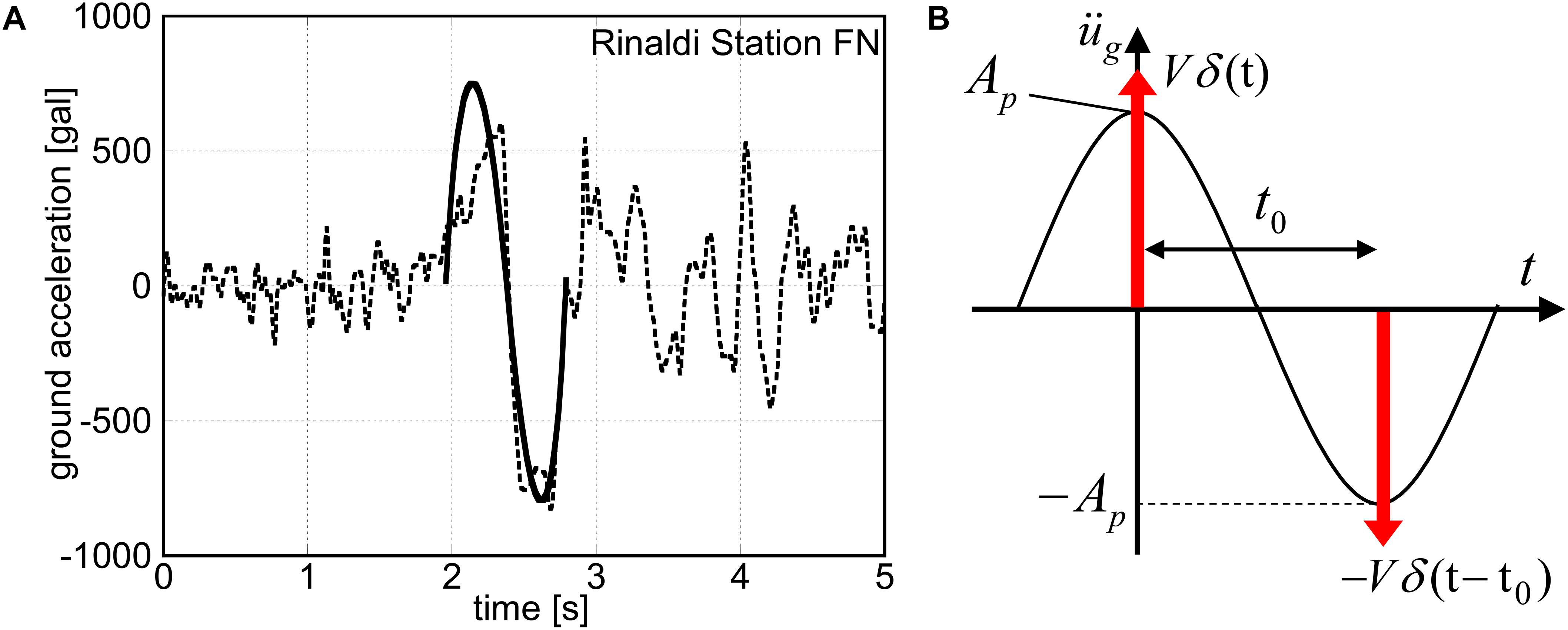
Figure 1. Modeling of the main part of ground motion into double impulse, (A) Transformation of principal part of Rinaldi station FN motion (Northridge 1994) into one-cycle sinusoidal wave, (B) Re-transformation into double impulse (Shiomi et al., 2018).
In Eqs. (1) and (2), Ap, ωp, V, t0 are the acceleration amplitude and circular frequency of the one-cycle sine wave, the velocity amplitude of the double impulse and the time interval of the two impulses, respectively, and δ(t) is the Dirac delta function. Kojima and Takewaki (2015) required the same maximum Fourier amplitude in this transformation to make their influences equivalent. This transformation is explained briefly in the following (Akehashi et al., 2018).
The Fourier transform of Eq. (2) can be expressed as
On the other hand, the Fourier transform of Eq. (1) can be computed by
From Eqs. (3), (4), the Fourier amplitudes of both inputs are expressed by
The ratio a of Ap to V as a principal index of this transformation is introduced by
The coefficient a as a function of t0 can be derived as follows from Eqs. (5)–(7) and the condition on the equivalence of the maximum Fourier amplitude .
In Eq. (8), it is obvious that . As for the denominator of Eq. (8), let us define the function f(x) = sin(x)/(π2−x2). The maximum value fmax of f(x) and the corresponding argument x = x0 can be obtained as follows (Akehashi et al., 2018).
After some manipulation of Eq. (8), a(t0) = 1/(πt0fmax) is derived.
Consider the ratio of the maximum velocity Vp of the one-cycle sine wave to the velocity amplitude V of the double impulse. The velocity of the one-cycle acceleration sine wave is expressed by
Eq. (11) provides the maximum velocity Vp of the one-cycle sine wave.
The relation a(t0) = 1/(πt0fmax) derived above and Eq. (12) lead to the relation between Vp and V.
From Eqs. (10) and (13), Vp/V is expressed as
The response correspondence between the one-cycle sine wave and the double impulse can be found in the reference (Kojima and Takewaki, 2015). This supports the validity of the use of the double impulse in place of the one-cycle sine wave and the near-fault ground motion.
Proposed Hysteretic-Viscous Hybrid (HVH) Damper
A new hysteretic-viscous hybrid (HVH) damper system was proposed in the recent paper (Hashizume and Takewaki, 2020). In this damper system, a gap mechanism is attached to a hysteretic damper in series (called DLA) and a viscous damper is used in parallel. The gap mechanism provides a trigger function for the hysteretic damper to delay its functioning. As a result, this hysteretic damper with a gap mechanism possesses a large-stroke performance and a function as a stopper.
The model of a MDOF building structure including the proposed HVH system is shown in Figure 2. It is assumed that the building structure as a shear building model and the hysteretic damper have the elastic-perfectly plastic restoring-force characteristics. In this figure, KFi, kL, ci denote the frame stiffness in the i-th story, the stiffness ratio of the hysteretic damper (DLA) to the frame (constant through all stories), and the damping coefficient of the viscous damper in the i-th story. The fundamental natural period of the bare frame is 3.15(s) as shown later and the story stiffness distribution of the bare frame is trapezoidal (the top to bottom story stiffness ratio = 0.5). It is assumed here that the damping coefficients of the viscous dampers are proportional to the elastic stiffnesses of the main frame. Let dy, dgh, dLy denote the yield inter-story drift of the frame, the trigger displacement of DLA, and the yield displacement of DLA, respectively (constant through all stories). On the other hand, the DHD system consists of DSA for the small-amplitude range and DLA for the large-amplitude range including a gap mechanism and the stiffness ratio of DLA to DSA is denoted by α. With these parameters, the stiffness of DSA in the i-th story is expressed by kKFi and the stiffness of DLA in the i-th story is expressed by αkKFi. In addition, fi and δi denote the story shear force in the i-th story of the frame or hysteretic dampers and the inter-story drift of the frame, respectively.
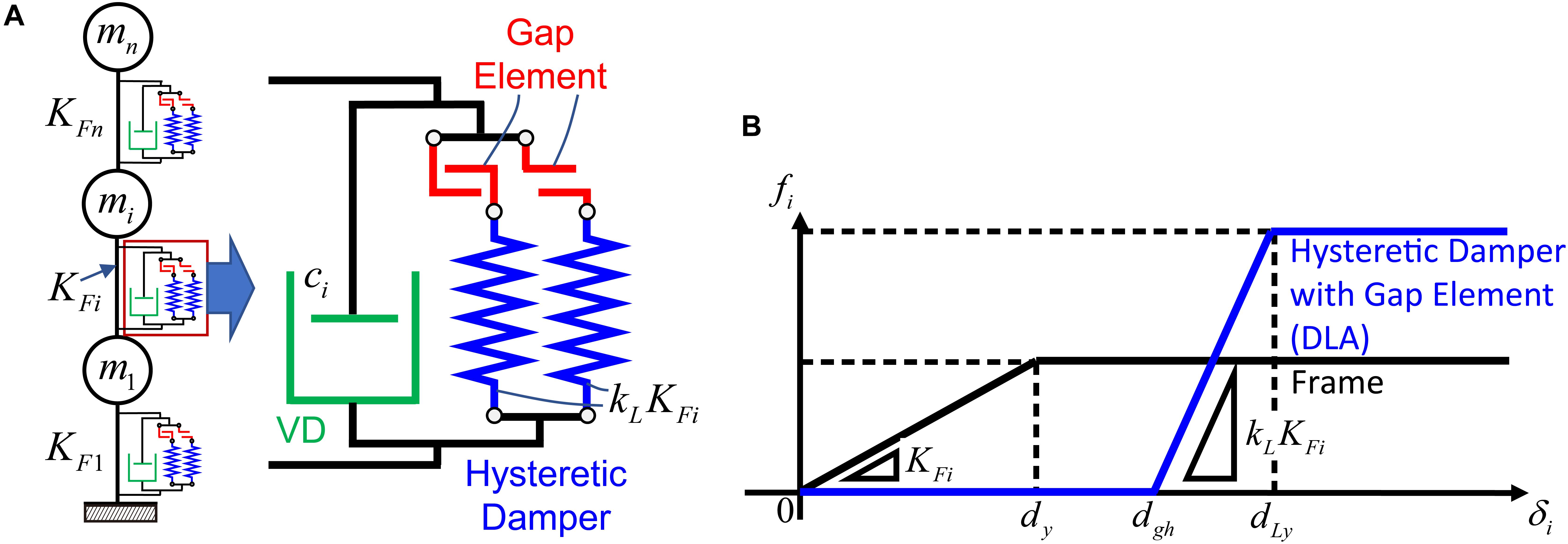
Figure 2. Elastic-perfectly plastic MDOF system with hysteretic-viscous hybrid (HVH) damper system, (A) Structural model with HVH damper system, (B) Story shear force-deformation relation of main frame and hysteretic damper with gap mechanism.
The viscous damper is aimed at resisting the broad-amplitude range vibration and the hysteretic damper with a gap mechanism is expected to work as a stopper for the large-amplitude range vibration.
Response Reduction by Hysteretic Damper With Gap Mechanism
In this section, the response reduction characteristic of the MDOF system with the HVH system is presented. Especially, the influence of DLA with gap mechanism as a stopper element will be focused. The structural parameters of the main frame, the viscous damper, and the hysteretic damper (DLA) in the MDOF system with the HVH system are shown in Table 1.
Table 1. Structural parameters of main frame, viscous damper, and hysteretic damper (HVH system).
The total story shear strength in the ith story can be expressed by Qyi = kFidy + kLkFi(dLy−dgh) = (1 + kL)kFidy and the corresponding yield shear force coefficient is expressed by cyi = (mj: jth story mass, g: acceleration of gravity). In addition, the strength ratio (ratio of the damper yield strength to the story yield strength of the entire system) is expressed by kLkFidy/{(1 + kL)kFidy} = kL/(1 + kL). Using the parameters in Table 1, the strength ratio becomes 0, 0.5, 0.67, 0.8 for kL = 0,1,2,4. It is known that this strength ratio has a significant influence on the global response of building structures with displacement-dependent energy dissipation devices (Inoue and Kuwahara, 1998; Oviedo et al., 2010). However, since the present hysteretic damper system includes a gap mechanism, the previous results cannot be applied directly.
The nonlinear time-history response analysis was conducted by using a Newmark-β method (constant acceleration method). The accuracy of the analysis program was confirmed through the comparison with the general-purpose computer program, ‘SNAP’ (SNAP, 2015).
The critical timing of the second impulse is obtained by conducting a time-history response analysis under the first impulse and finding the time attaining the zero value of the sum of restoring force and damping force of the damper in the first story (Akehashi and Takewaki, 2019).
Figure 3 illustrates the frame ductility factor distributions of inter-story drift for various stiffness ratios kL = 0, 1, 2, 4 of DLA to the main frame and the maximum frame ductility factor with respect to stiffness ratio kL of DLA to the main frame in the MDOF system with the HVH system under the critical double impulse for various velocity levels V = 1.0, 1.5, 2.0 (m/s).
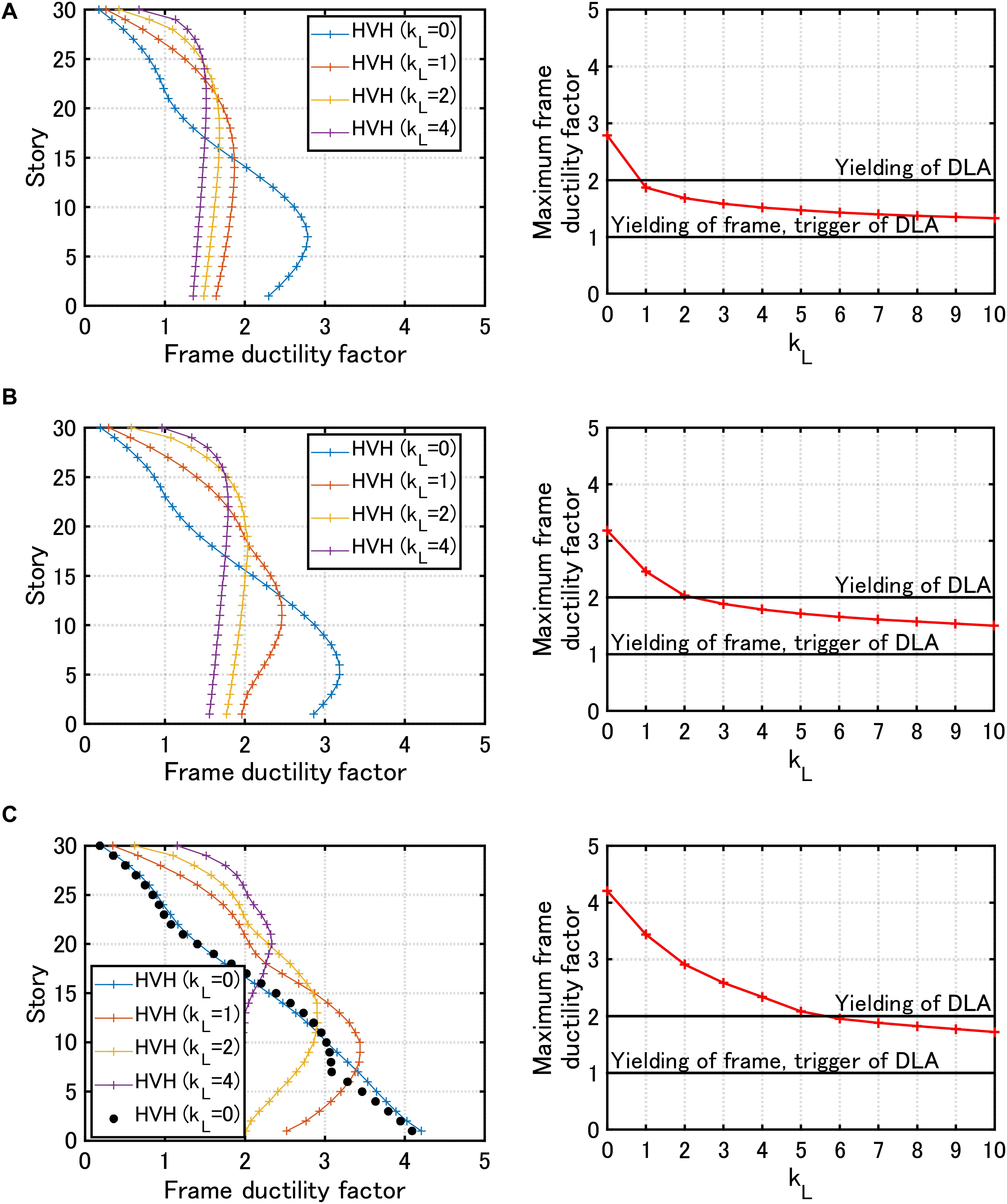
Figure 3. Frame ductility factor distribution of inter-story drift for various stiffness ratios kL = 0, 1, 2, 4 of the hysteretic damper (DLA) to the main frame (left) and maximum frame ductility factor with respect to kL (right) in the MDOF system with the HVH system under critical double impulse, (A) Velocity level of double impulse V = 1.0 (m/s), (B) V = 1.5 (m/s), (C) V = 2.0 (m/s) (solid black circles indicate responses to corresponding one-cycle sine wave).
It can be seen that, in the MDOF model without DLA (kL = 0), a remarkable damage concentration can be observed in lower stories. This phenomenon is often encountered when ordinary tall building structures without special passive dampers (like a stopper system) are subjected to a pulse-type ground motion. As the value kL becomes larger, the maximum frame ductility factor becomes smaller and its distribution approaches a nearly uniform one. It is noted that, when the input velocity is large (Figure 3C), DLA yields and the uniformity break down a little bit. Furthermore, it can be found that DLA works in the elastic range when kL becomes larger than an appropriate value (kL = 1 for V = 1.0 (m/s), kL = 2 for V = 1.5 (m/s), kL = 6 for V = 2.0 (m/s)). In Figure 3C, the frame ductility factor distribution to the corresponding one-cycle sine wave for kL = 0 and V = 2.0 (m/s) is plotted with solid black circles for comparison. It can be seen that the critical double impulse is a good substitute of the corresponding one-cycle sine wave. In the input transformation, Eqs. (7)–(14) were used.
Model Parameter Setting for HVH Damper System and DHD Damper System
In this section, the model parameter setting is presented for the HVH damper system and the DHD damper system.
Figure 4 shows the MDOF systems with the HVH damper system (Figures 4A,B) and the DHD damper system (Figures 4C,D). The story shear force-inter-story drift relations for both models are also presented. In the later analysis, the case of dgh = dy and dLy = 2dy is treated. Figure 5 indicates the equivalence condition of the viscous damper in the HVH system and the hysteretic damper (DSA) in the DHD system.
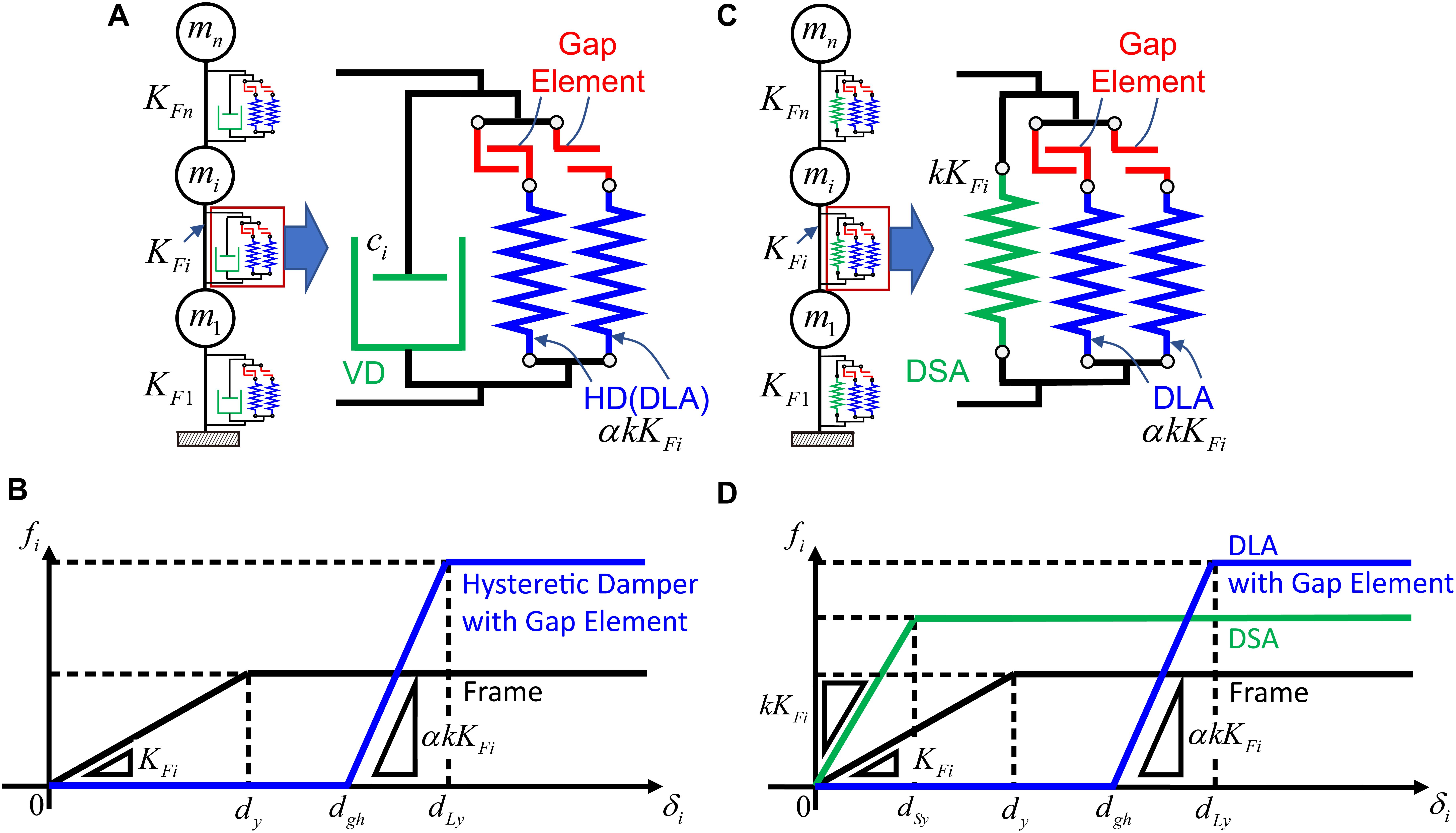
Figure 4. MDOF systems with different damper systems, (A) MDOF system with HVH system, (B) Story shear force-inter-story drift relation of MDOF system with HVH system, (C) MDOF system with DHD system, (D) Story shear force-inter-story drift relation of MDOF system with DHD system.
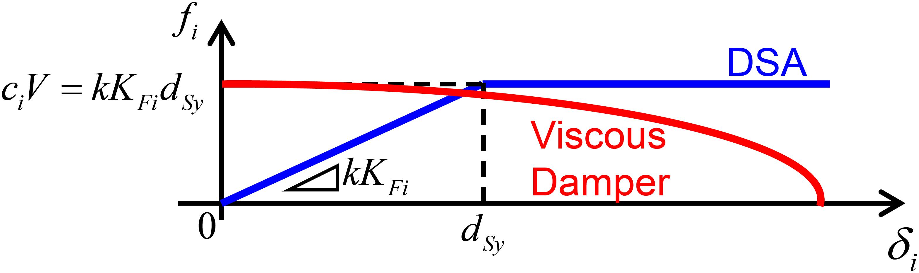
Figure 5. Equivalence condition of viscous damper in HVH system and hysteretic damper (DSA) in DHD system.
Let us introduce the following equivalence condition between the damping force ciV in the viscous damper and the yielding force kKFidsy of the DSA in the i-th story.
This guarantees the equivalence of the maximum forces in the HVH system (viscous damper) and the DHD system (DSA). Since it is assumed here that the damping coefficients of the viscous dampers are proportional to the elastic stiffnesses of the main frame, the following relation holds for the initial stiffness matrix of the main frame [K], the damping matrix of the viscous dampers [C], the undamped fundamental natural circular frequency ω1, and the damping ratio h1 of the viscous dampers.
Eq. (16) provides the following relation.
From Eqs. (15) and (17), the stiffness ratio k of DSA to the main frame can be expressed in terms of h1 of the viscous dampers.
In this paper, the damping coefficients were determined for the lowest mode. Although the lowest vibration component is predominant in elastic building structures under usual ground motions (especially in deformation components), higher mode effects may be non-negligible in elastic-plastic building structures (Akehashi and Takewaki, 2020).
For the equivalence condition, the specification of the input velocity level of the double impulse is necessary. V = 1.0(m/s) is used throughout this paper. Table 2 shows the structural parameters of the main frame and two hysteretic dampers in the DHD system. By using the parameters in Table 2, the relation of Eq. (18) can be expressed as shown in Figure 6A. It should be noted that Table 1 was only used for the analysis in Figure 3 and the stiffness of DLA in the DHD system shown in Table 2 is used in the later analysis of the HVH system. Therefore, the DLA is the same in the HVH and the DHD.
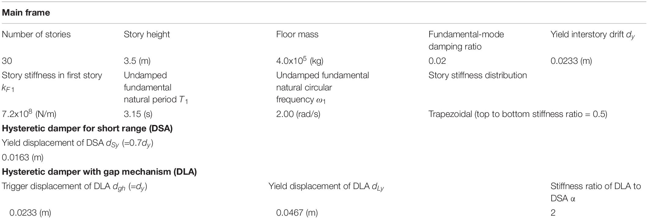
Table 2. Structural parameters of main frame and two hysteretic dampers (DHD system).
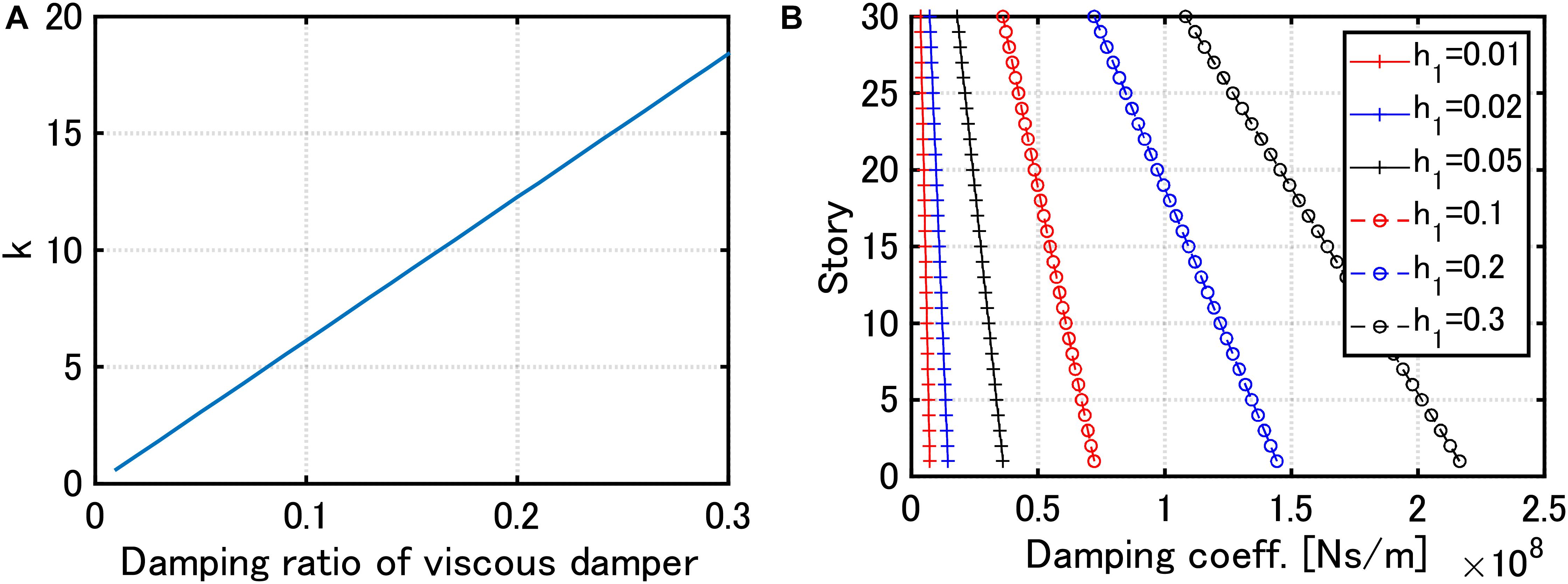
Figure 6. Damper properties, (A) Stiffness ratio k of DSA in DHD to main frame with respect to damping ratio h1 of viscous damper in HVH (using Eq. (18) for V = 1.0(m/s)), (B) Damping coefficient ci of viscous dampers in HVH for several damping ratios.
Response Comparison Between MDOF System With HVH System and MDOF System With DHD System
In this section, the responses of the MDOF system with the HVH system and the MDOF system with the DHD system are compared.
Figure 7 shows the frame ductility factor distributions of inter-story drift in the MDOF system with the HVH system for various damping levels of viscous dampers h1 = 0.01,0.02,0.05,0.1,0.2,0.3 and the MDOF system with the DHD system of the equivalent damper quantity of DSA (using Eq. (18)) under the critical double impulse with V = 2.0 (m/s). The damping coefficients ci of viscous dampers in the HVH system are shown in Figure 6B. It can be observed that, in the case of h1 = 0.01,0.02, the response reduction effect is larger in the DHD system. On the other hand, as the viscous damper quantity in the HVH system becomes larger, the response reduction effect is larger in the HVH system. However, the response reduction effects of both damper systems do not differ so much.
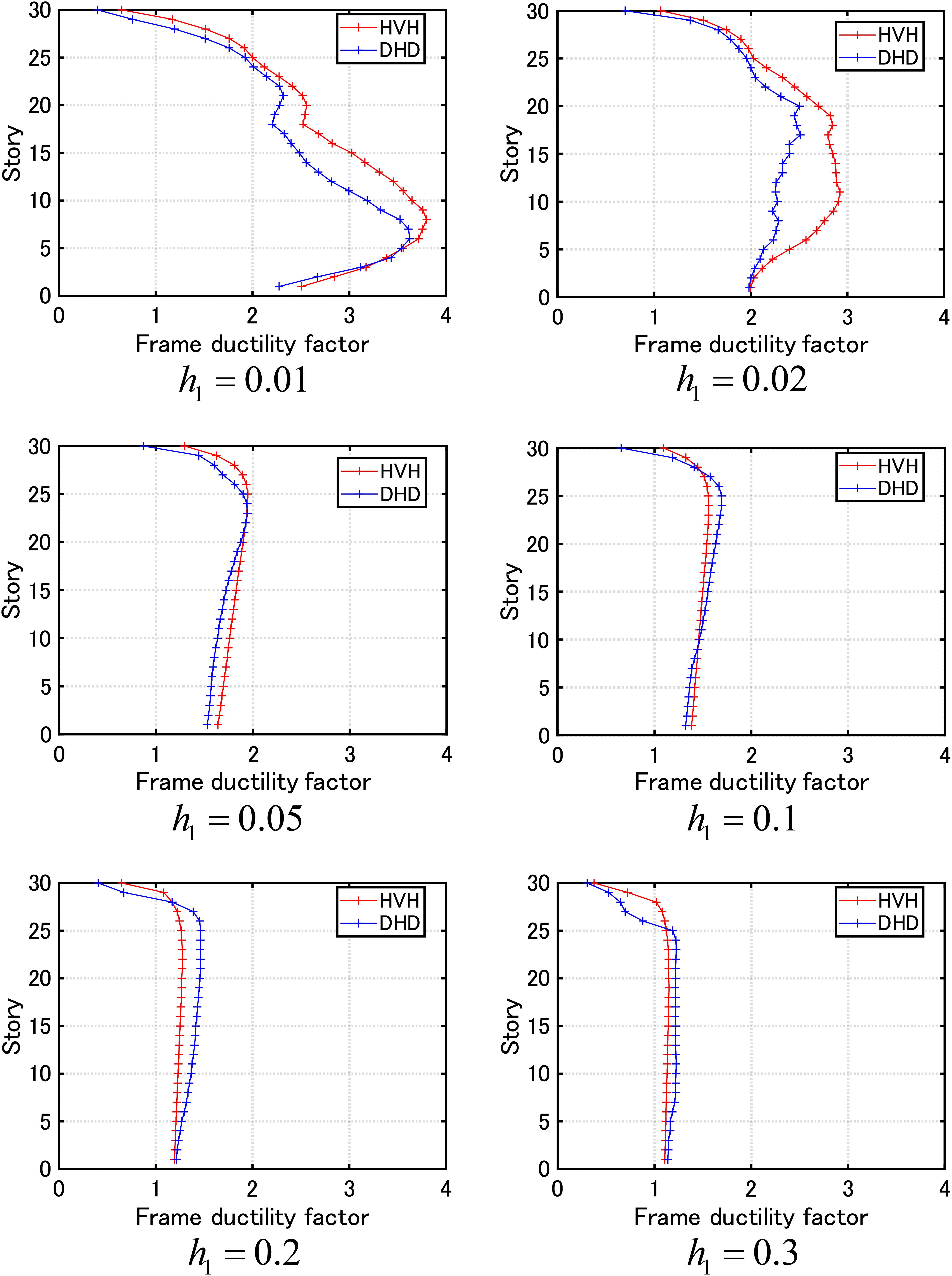
Figure 7. Frame ductility factor distribution of inter-story drift in MDOF systems with HVH system for various damping levels h1 = 0.01,0.02,0.05,0.1,0.2,0.3 of viscous dampers and with DHD system of equivalent damper quantity of DSA (using Eq. (18)) under critical double impulse with V = 2.0 (m/s).
On the other hand, Figure 8 presents the time histories of the 15th-story inter-story drifts of the MDOF system with the HVH system for various damping levels h1 = 0.01,0.02,0.05,0.1,0.2,0.3 of viscous dampers and the MDOF system with the DHD system of the equivalent damper quantity of DSA (using Eq. (18)) under the critical double impulse with V = 2.0 (m/s). Furthermore, Figure 9 illustrates similar time histories for the 30th-story inter-story drifts. It can be seen that, although the 15th-story inter-story drifts of both damper systems (HVH and DHD) do not differ so much in the case of h1 = 0.05,0.1 (Figure 7), the MDOF system with the DHD system exhibits a larger residual deformation. Since DLA does not go into the plastic range, this residual deformation seems to result from the plastic deformation of DSA. In addition, in the case of h1 = 0.01,0.02, the 15th-story inter-story drifts of both damper systems (HVH and DHD) cause large residual deformations. Since DLA goes into the plastic range in both HVH and DHD systems, this residual deformation seems to result from the plastic deformation of DLA. On the other hand, the 30th-story inter-story drifts of both damper systems (HVH and DHD) do not cause so much large residual deformation. This is because the maximum 30th-story inter-story drifts of both damper systems (HVH and DHD) are not so large and both models almost remain in the elastic range.
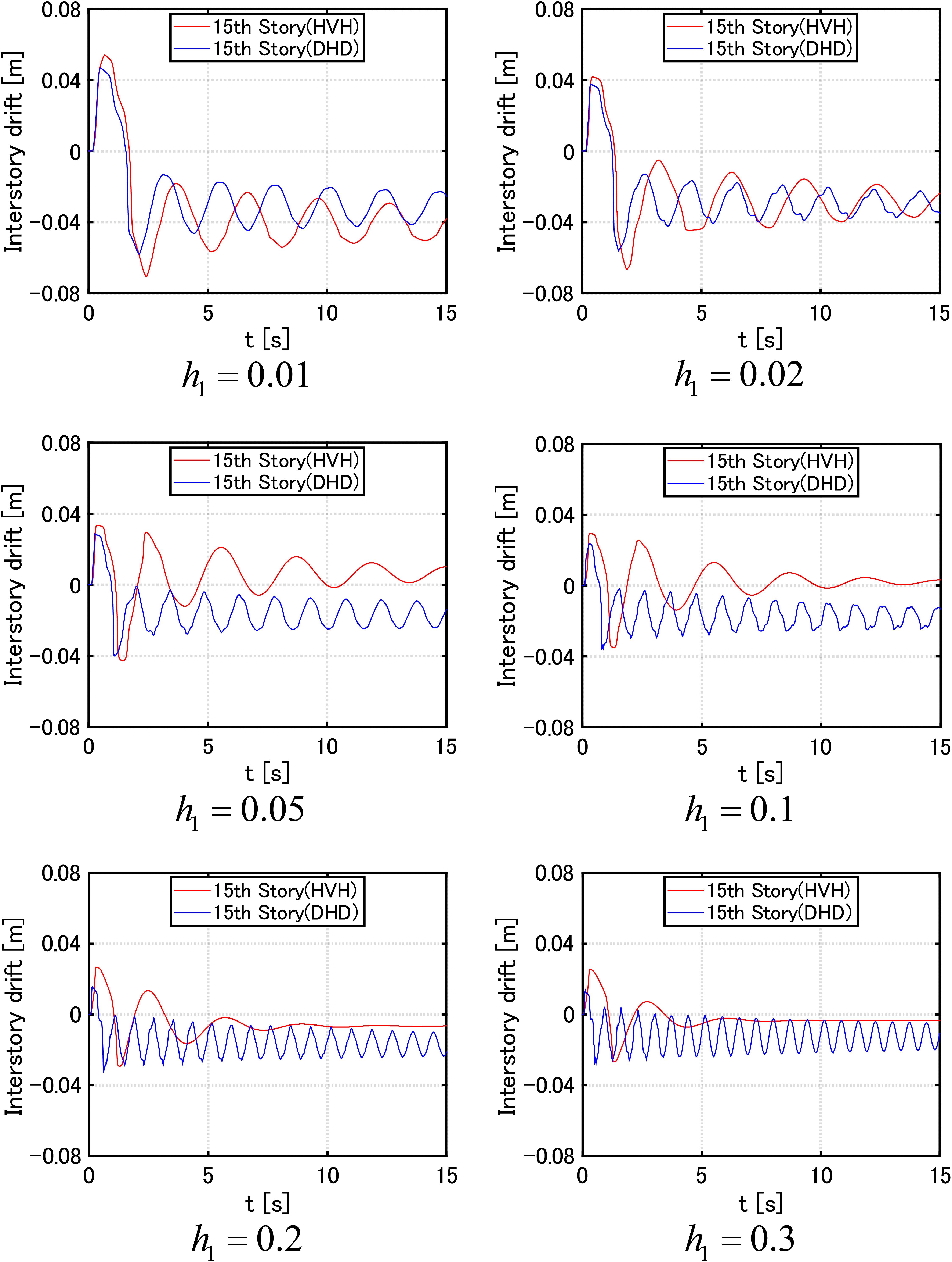
Figure 8. Time history of 15th-story inter-story drift of MDOF systems with HVH system for various damping levels h1 = 0.01,0.02,0.05,0.1,0.2,0.3 of viscous dampers and with DHD system of equivalent damper quantity of DSA (using Eq. (18)) under critical double impulse with V = 2.0 (m/s).
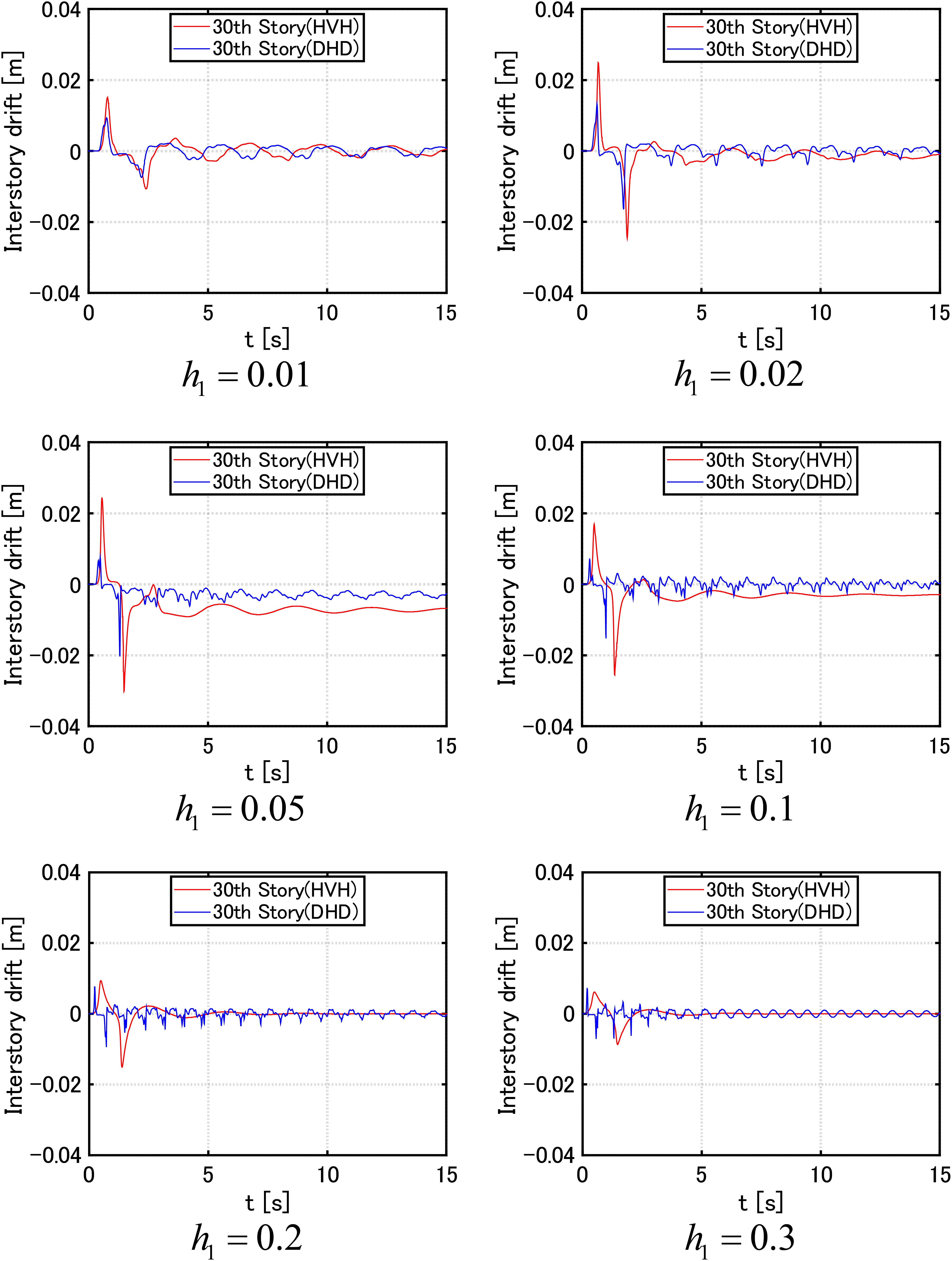
Figure 9. Time history of 30th-story inter-story drift of MDOF systems with HVH system for various damping levels h1 = 0.01,0.02,0.05,0.1,0.2,0.3 of viscous dampers and with DHD system of equivalent damper quantity of DSA (using Eq. (18)) under critical double impulse with V = 2.0 (m/s).
Double Impulse Pushover (DIP) Analysis
In this section, the characteristic of damage concentration for increasing input level is clarified for both the MDOF system with the HVH system and the MDOF system with the DHD system. This analysis is completed by using the double impulse pushover (DIP) analysis proposed by Akehashi and Takewaki (2019). In the DIP analysis, the critical timing of the second impulse is computed for a specified input level by conducting a time-history response analysis under the first impulse and finding the time attaining the zero value of the sum of restoring force and damping force of the damper in the first story. Then, this procedure is repeated for the increasing input velocity level (Akehashi and Takewaki, 2019).
Figure 10 shows the results of the DIP analysis (V = 0.3–3.0 (m/s) with increment 0.3 (m/s)) for the MDOF system with the HVH system for various damping levels h1 = 0.01,0.02,0.05,0.1,0.2,0.3 of viscous dampers and the MDOF system with DHD system of the equivalent damper quantity of DSA (using Eq. (18) for V = 1.0 (m/s)). It can be observed that, in the case of h1 = 0.01, as the input velocity level increases, the damage concentration occurs in the middle stories in both systems of HVH and DHD. On the other hand, in the case of h1 = 0.02, a different phenomenon occurs as the input velocity level increases. While the damage concentration occurs in the middle stories for the HVH system, that occurs in the lower stories for the DHD system. When the fundamental damping ratio attains h1 = 0.1,0.2,0.3, the frame ductility factor distribution exhibits almost uniform distribution in both damper systems even for the input velocity level V = 3.0(m/s) and DLA almost remains in the elastic range. Since the DIP analysis only seeks for the critical resonant case, it is appropriate for clarifying the system’s critical performance for the increasing input level.

Figure 10. Double impulse pushover (DIP) analysis (V = 0.3–3.0 (m/s) with increment 0.3 (m/s)) for MDOF systems with HVH system for various damping levels h1 = 0.01,0.02,0.05,0.1,0.2,0.3 of viscous dampers and with DHD system of equivalent damper quantity of DSA (using Eq. (18) for V = 1.0 (m/s)) (−HVH; −DHD).
Figure 11 presents the maximum frame ductility factor with respect to the input velocity level of the double impulse for the MDOF system with HVH system for various damping levels h1 = 0.01,0.02,0.05,0.1,0.2,0.3 of viscous dampers and the MDOF system with DHD system of the equivalent damper quantity of DSA (using Eq. (18) for V = 1.0(m/s)). It can be understood that, in the case of h1 = 0.01,0.02,0.05, the DHD damper system exhibits a higher response reduction performance for a wide range of input level. On the other hand, in the case of h1 = 0.1,0.2,0.3, the HVH damper system is superior to the DHD damper system in the larger input velocity range. However, its difference is quite small.
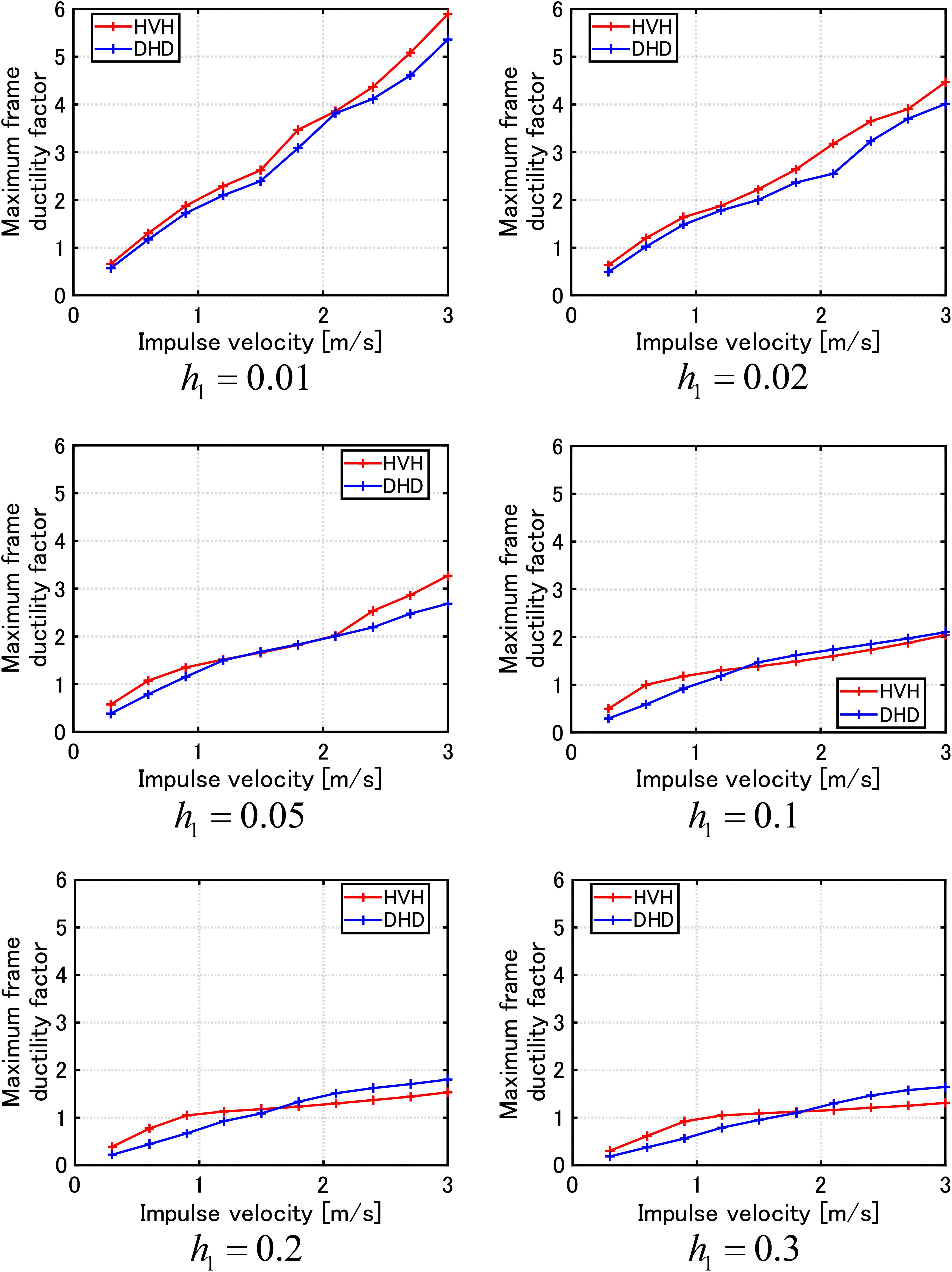
Figure 11. Maximum frame ductility factor with respect to input velocity level of double impulse for MDOF systems with HVH system for various damping levels h1 = 0.01,0.02,0.05,0.1,0.2,0.3 of viscous dampers and with DHD system of equivalent damper quantity of DSA (using Eq. (18) for V = 1.0 (m/s)).
Response Comparison of MDOF Building Model Including HVH System With Building Model Including DHD System Under Recorded Ground Motion of Extremely Large Amplitude
The effectiveness of the HVH system and the DHD system in the MDOF building model under a recorded long-period pulse-type ground motion of extremely large amplitude is shown in this section. Figures 12A,B show a ground acceleration time history and the corresponding velocity time history of the JMA Nishiharamura-Komori (EW) wave during the Kumamoto earthquake in 2016. This ground motion is known as a long-period pulse-type ground motion of extremely large velocity amplitude. While the maximum velocity level of severe earthquake ground motions in the code for tall buildings in Japan is 0.5 m/s, the recorded one in the Kumamoto earthquake is over 2.0 m/s. Figures 12C–F show the displacement, velocity, acceleration response spectra, and the input energy spectrum (Ordaz et al., 2003). It can be understood that this ground motion has a large velocity response around 0.7, 3.0(s) and the intensity around 3.0(s) is expected to influence the response of the present MDOF model with the HVH of the fundamental natural period 3.15(s). Furthermore, it is noted that, since the MDOF model with the DHD possesses DSA, its fundamental natural period is shorter than 3.15(s). It should also be remarked that this recorded ground motion is not necessarily critical to the MDOF systems with the HVH system and with the DHD system because both models will experience the large plastic response.
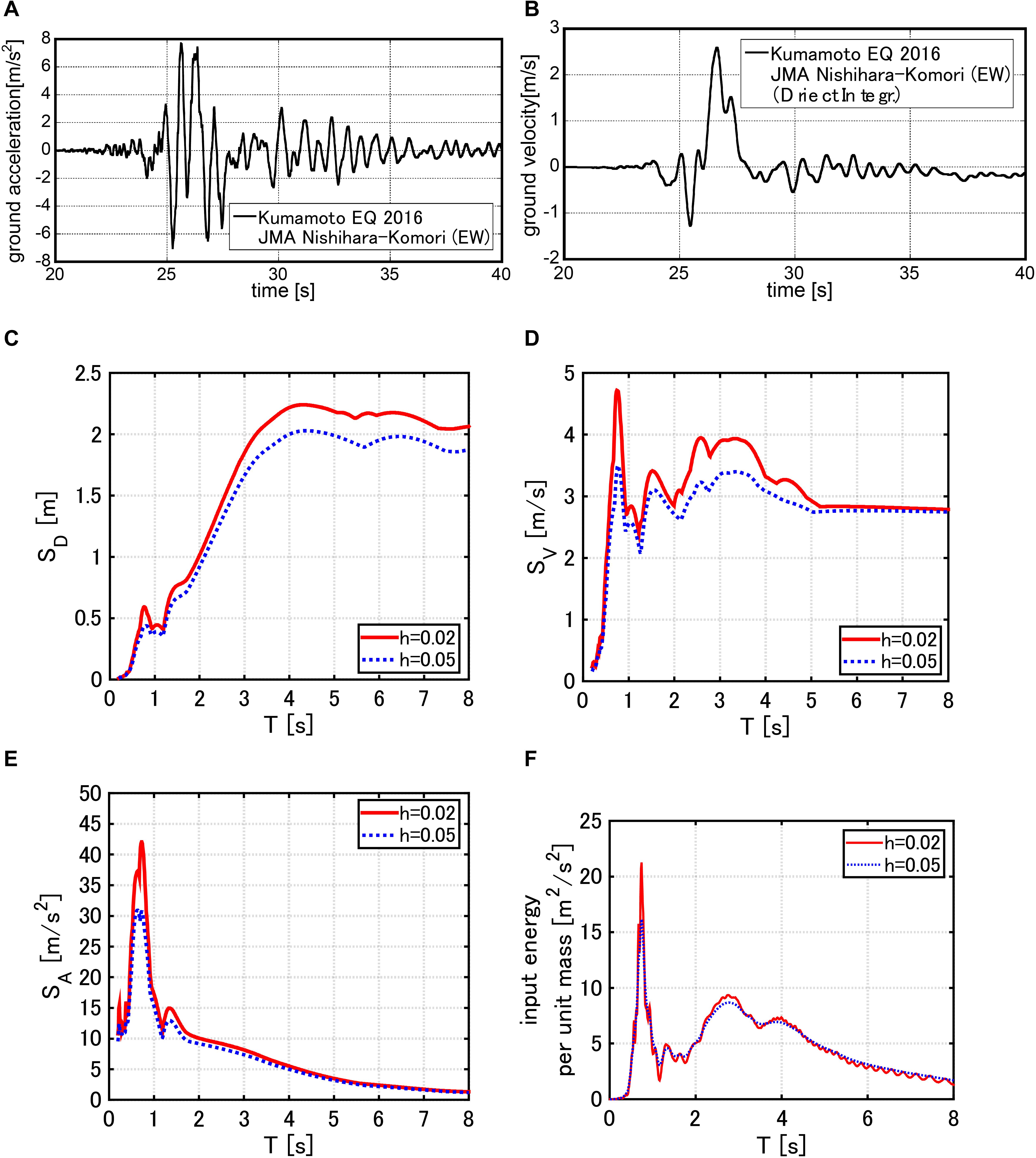
Figure 12. Long-period pulse-type ground motion of extremely large amplitude, (A) Ground acceleration of JMA Nishiharamura-Komori (EW) wave, (B) Ground velocity of JMA Nishiharamura-Komori (EW) wave, (C) Displacement response spectrum, (D) Velocity response spectrum, (E) Acceleration response spectrum (Hashizume and Takewaki, 2020), and (F) Input energy spectrum.
Figure 13 indicates the comparison of frame ductility factor distributions of inter-story drift in the MDOF system with the HVH system for various damping levels h1 = 0.01,0.02,0.05,0.1,0.2,0.3 of viscous dampers and the MDOF system with the DHD system of the equivalent damper quantity of DSA (using Eq. (18) for V = 1.0(m/s)) under the JMA Nishiharamura-Komori (EW). It can be observed that the DHD system exhibits a high response reduction performance for various damping levels h1 = 0.01,0.02,0.05,0.1 of viscous dampers under this recorded ground motion. More specifically, when the damping levels of viscous dampers are h1 = 0.01,0.02, the frame ductility factor exceeds 2 and DLA goes into the plastic range. In addition, some damage concentration can be observed in lower and middle stories. On the other hand, when the damping levels of viscous dampers are h1 = 0.05,0.1,0.2,0.3, the frame ductility factor does not exceed 2 approximately and DLA remains in the elastic range. In addition, no damage concentration is observed. It is important to note again that the MDOF system with the DHD system has a fundamental natural period shorter than 3.15(s) of the bare frame (and also the MDOF system with HVH system) due to the existence of DSA. Judging from the response spectra in Figure 12 (displacement and velocity response spectra decrease when the natural period becomes shorter than 3.0(s)), this change of the fundamental natural period brought a difference in the frame ductility factors in Figure 13. Although some attempts to scale the ground motion for respective control systems (HVH and DHD) can be considered in the comparison, the simultaneous modification in the amplitude and time scales may be meaningful from the viewpoint of resonance. For this purpose, it seems that the DIP analysis shown in Figures 10, 11 is superior to the analysis for the recorded ground motion because only the critical resonant case is sought depending on the level of plastic response and the intrinsic characteristic on the performance of damper systems can be captured in a reliable and reasonable way.
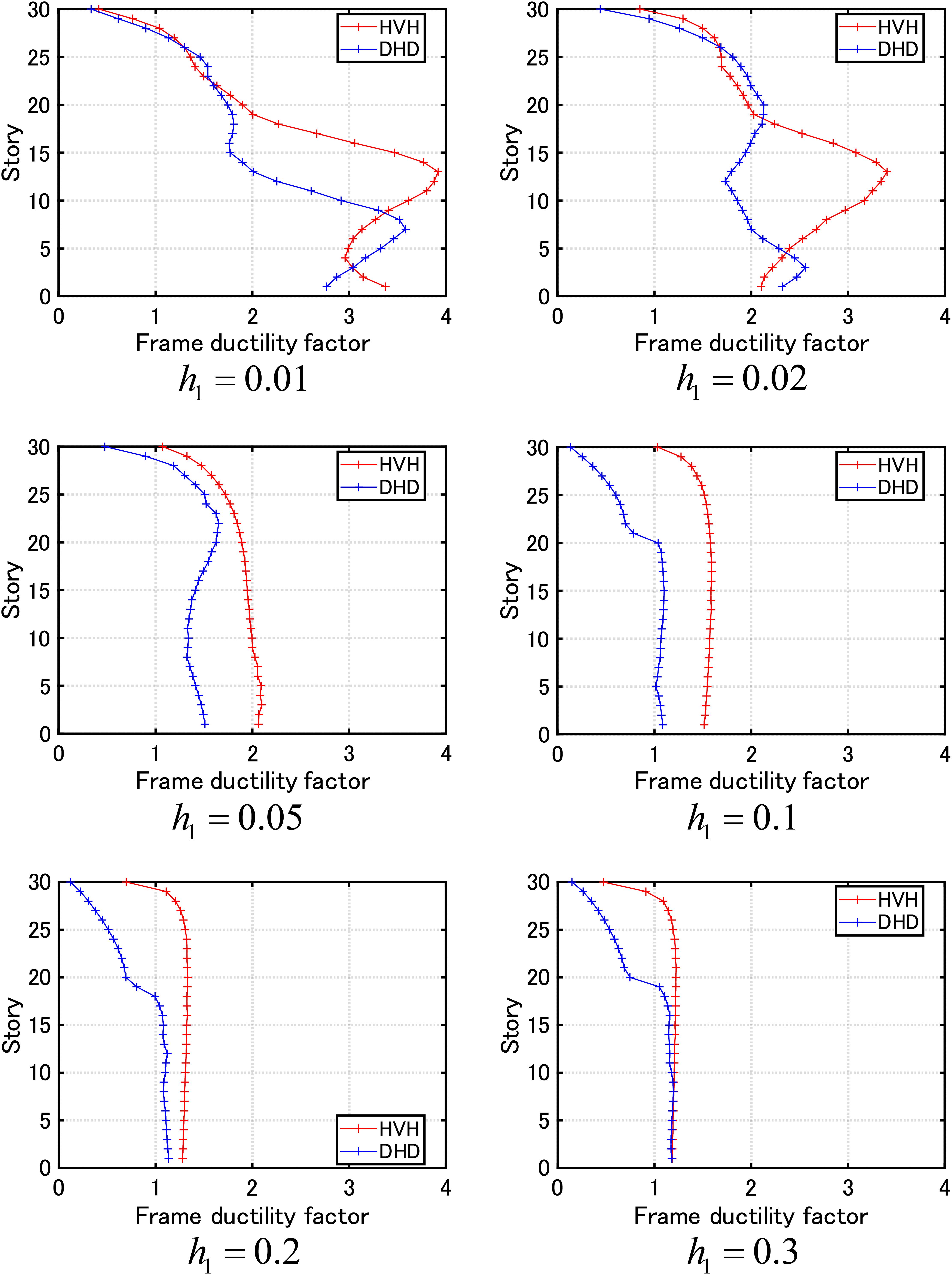
Figure 13. Frame ductility factor distribution of inter-story drift in MDOF systems with HVH system for various damping levels h1 = 0.01,0.02,0.05,0.1,0.2,0.3 of viscous dampers and with DHD system of equivalent damper quantity of DSA (using Eq. (4) for V = 1.0 (m/s)) under JMA Nishiharamura-Komori (EW) wave.
Conclusion
The viscous-hysteretic hybrid (HVH) damper system proposed in the previous paper for a single-degree-of-freedom (SDOF) system was extended to a multi-degree-of-freedom (MDOF) system subjected to pulse-type earthquake ground motions of an extremely large amplitude. The HVH system consists of a viscous damper and a hysteretic damper with a gap mechanism as a stopper. The following conclusions were derived.
1. Since the pulse-type earthquake ground motion of extremely large amplitude causes a complicated catastrophic effect on tall buildings, the treatment of tall buildings as MDOF systems is inevitable for a reliable analysis of its effect. The effectiveness of the HVH system in tall buildings was analyzed and demonstrated.
2. A double impulse was used as a substitute for pulse-type ground motions of extremely large amplitude. Time-history response analyses were performed for an amplitude modulated critical double impulse to investigate the effectiveness of the proposed HVH system. It was demonstrated that the HVH system is effective for various levels of the double impulse which causes a large plastic deformation. The hysteretic damper with a gap mechanism as a stopper element plays an important role in the effective reduction of concentrated plastic deformations.
3. The double impulse pushover (DIP) analysis, which was proposed by Akehashi and Takewaki (2019), was conducted and revealed the critical resonant performance of elastic-plastic tall buildings. It was demonstrated that the HVH system is also effective for gradually increasing critical double impulse. In addition, an analysis to a recorded ground motion at Kumamoto (2016) was conducted. It was clarified that the HVH system also has a good performance for a recorded ground motion of extremely large amplitude.
4. The comparison with the formerly proposed dual hysteretic damper (DHD) system composed of parallel-type small and large-amplitude hysteretic dampers was also conducted. The large-amplitude hysteretic damper includes a gap mechanism as in the HVH system. It was shown that the performance of the HVH system is almost equivalent to the DHD system except in a few examples and the small residual deformation of the HVH system is an advantageous feature.
Data Availability Statement
The raw data supporting the conclusions of this article will be made available by the authors, without undue reservation.
Author Contributions
SH formulated the problem, conducted the computation, and wrote the manuscript. IT supervised the research and wrote the manuscript. Both authors contributed to the article and approved the submitted version.
Funding
Part of the present work is supported by the Grant-in-Aid for Scientific Research (KAKENHI) of Japan Society for the Promotion of Science (No. 18H01584). This support is greatly appreciated.
Conflict of Interest
The authors declare that the research was conducted in the absence of any commercial or financial relationships that could be construed as a potential conflict of interest.
References
Adachi, F., Fujita, K., Tsuji, M., and Takewaki, I. (2013a). Importance of interstory velocity on optimal alongheight allocation of viscous oil dampers in super highrise buildings. Eng. Struct 56, 489–500. doi: 10.1016/j.engstruct.2013.05.036
Adachi, F., Yoshitomi, S., Tsuji, M., and Takewaki, I. (2013b). Nonlinear optimal oil damper design in seismically controlled multi-story building frame. Soil Dyn. Earthq. Eng. 44, 1–13. doi: 10.1016/j.soildyn.2012.08.010
Aiken, I. D., Nims, D. K., Whittaker, A. S., and Kelly, J. M. (1993). Testing of passive energy dissipation systems. Earthq. Spectra 9, 335–370. doi: 10.1193/1.1585720
Akehashi, H., Kojima, K., and Takewaki, I. (2018). Critical response of SDOF damped bilinear hysteretic system under double impulse as substitute for near-fault ground motion. Front. Built Environ. 4:5. doi: 10.3389/fbuil.2018.00005
Akehashi, H., and Takewaki, I. (2019). Optimal viscous damper placement for elastic-plastic MDOF structures under critical double impulse. Front. Built Environ. 5:20. doi: 10.3389/fbuil.2019.00020
Akehashi, H., and Takewaki, I. (2020). Comparative investigation on optimal viscous damper placement for elastic-plastic MDOF structures: transfer function amplitude or double impulse. Soil Dyn. Earthq. Eng. 130:105987. doi: 10.1016/j.soildyn.2019.105987
Attard, T. L. (2007). Controlling all interstory displacements in highly nonlinear steel buildings using optimal viscous damping. J. Struct. Eng. ASCE 133, 1331–1340. doi: 10.1061/(asce)0733-9445(2007)133:9(1331)
Austin, M. A., and Pister, K. S. (1985). Design of seismic-resistant friction-braced frames. J. Struct. Eng. ASCE 111, 2751–2769. doi: 10.1061/(asce)0733-9445(1985)111:12(2751)
Aydin, E., Boduroglub, M. H., and Guney, D. (2007). Optimal damper distribution for seismic rehabilitation of planar building structures. Eng. Struct. 29, 176–185. doi: 10.1016/j.engstruct.2006.04.016
Bruneau, M., Chang, S. E., Eguchi, R. T., Lee, G. C., O’Rourke, T. D., Reinhorn, A. M., et al. (2003). A framework to quantitatively assess andenhance the seismic resilience of communities. Earthq. Spectra 19, 733–752. doi: 10.1193/1.1623497
Caughey, T. K. (1960). Sinusoidal excitation of a system with bilinear hysteresis. J. Appl. Mech. 27, 640–643. doi: 10.1115/1.3644075
Cherry, S., and Filiatraut, A. (1993). Seismic response control of buildings using friction damper. Earthq. Spectra 9, 447–466. doi: 10.1193/1.1585724
Ciampi, V., Angelis, M. D., and Paolacci, F. (1995). Design of yielding or friction-based dissipative bracings for seismic protection of buildings. Eng. Struct. 17, 381–391. doi: 10.1016/0141-0296(95)00021-x
Cimellaro, G., Reinhorn, A., and Bruneau, M. (2010). Framework for analytical quantification of disaster resilience. Eng. Struct. 32, 3639–3649. doi: 10.1016/j.engstruct.2010.08.008
Domenico, D. D., Ricciardi, G., and Takewaki, I. (2019). Design strategies of viscous dampers for seismic protection of building structures: a review. Soil Dyn. Earthq. Eng. 118, 144–165. doi: 10.1016/j.soildyn.2018.12.024
Filiatrault, A., and Cherry, S. (1990). Seismic design spectra for friction-damped structure. J. Struct. Eng. ASCE 116, 1334–1355. doi: 10.1061/(asce)0733-9445(1990)116:5(1334)
Fukumoto, Y., and Takewaki, I. (2017). Dual control high-rise building for robuster earthquake performance. Front. Built Environ. 3:12. doi: 10.3389/fbuil.2017.00012
Hanson, R. D. (1993). Supplemental damping for improved seismic performance. Earthq. Spectra 9, 319–334. doi: 10.1193/1.1585719
Hanson, R. D., and Soong, T. T. (2001). Seismic Design With Supplemental Energy Dissipation Devices. Oakland, CA: EERI.
Hashizume, S., and Takewaki, I. (2020). Hysteretic-viscous hybrid damper system for long-period pulse-type earthquake ground motions of large amplitude. Front. Built Environ. 6:62. doi: 10.3389/fbuil.2020.00062
Hayashi, K., Fujita, K., Tsuji, M., and Takewaki, I. (2018). A simple response evaluation method for base-isolation building-connection hybrid structural system under long-period and long-duration ground motion. Front. Built Environ. 4:2. doi: 10.3389/fbuil.2018.00002
Inoue, K., and Kuwahara, S. (1998). Optimum strength ratio of hysteretic damper. Earthq. Eng. Struct. Dyn. 27, 577–588. doi: 10.1002/(sici)1096-9845(199806)27:6<577::aid-eqe743>3.0.co;2-u
Kawai, A., Maeda, T., and Takewaki, I. (2020). Smart seismic control system for high-rise buildings using large-stroke viscous dampers through connection to strong-back core frame. Front. Built Environ. 6:29. doi: 10.3389/fbuil.2020.00029
Kojima, K., and Takewaki, I. (2015). Critical earthquake response of elastic-plastic structures under near-fault ground motions (Part 1: Fling-step input). Front. Built Environ. 1:12. doi: 10.3389/fbuil.2015.00012
Kojima, K., and Takewaki, I. (2016). A simple evaluation method of seismic resistance of residential house under two consecutive severe ground motions with intensity 7. Front. Built Environ. 2:15. doi: 10.3389/fbuil.2016.00015
Kondo, K., and Takewaki, I. (2019). Simultaneous approach to critical fault rupture slip distribution and optimal damper placement for resilient building design. Front. Built Environ. 5:126. doi: 10.3389/fbuil.2019.00126
Lagaros, N., Plevris, V., and Mitropoulou, C. C. (eds) (2013). Design Optimization of Active and Passive Structural Control Systems. Pennsylvania: IGI Global.
Lavan, O., and Levy, R. (2010). Performance based optimal seismic retrofitting of yielding plane frames using added viscous damping. Earthq. Struct. 1, 307–326. doi: 10.12989/eas.2010.1.3.307
Makita, K., Murase, M., Kondo, K., and Takewaki, I. (2018). Robustness evaluation of base- isolation building-connection hybrid controlled building structures considering uncertainties in deep ground. Front. Built Environ. 4:16. doi: 10.3389/fbuil.2018.00016
Murakami, Y., Noshi, K., Fujita, K., Tsuji, M., and Takewaki, I. (2013a). Optimal placement of hysteretic dampers via adaptive smoothing algorithm. ICEAS 13, 1821–1835.
Murakami, Y., Noshi, K., Fujita, K., Tsuji, M., and Takewaki, I. (2013b). Simultaneous optimal damper placement using oil, hysteretic and inertial mass dampers. Earthq. Struct. 5, 261–276. doi: 10.12989/eas.2013.5.3.261
Nakashima, M., Saburi, K., and Tsuji, B. (1996). Energy input and dissipation behaviour of structures with hysteretic dampers. Earthq. Eng. Struct. Dyn. 25, 483–496. doi: 10.1002/(sici)1096-9845(199605)25:5<483::aid-eqe564>3.0.co;2-k
Noroozinejad, E., Takewaki, I., Yang, T. Y., Astaneh-Asl, A., and Gardoni, P. (eds) (2019). Resilient Structures and Infrastructures. Berlin: Springer.
Ogawa, Y., Kojima, K., and Takewaki, I. (2017). General evaluation method of seismic resistance of residential house under multiple consecutive severe ground motions with high intensity. Int. J. Earthq. Impact Eng. 2, 158–174. doi: 10.1504/ijeie.2017.10010044
Ordaz, M., Huerta, B., and Reinoso, E. (2003). ‘Exact computation of input-energy spectra from Fourier amplitude spectra. Earthq. Eng. Struct. Dyn. 32, 597–605. doi: 10.1002/eqe.240
Oviedo, A. J. A., Midorikawa, M., and Asari, T. (2010). Earthquake response of ten-story story-driftcontrolled reinforced concrete frames with hysteretic dampers. Eng. Struct. 32, 1735–1746. doi: 10.1016/j.engstruct.2010.02.025
Pall, A. S., and Marsh, C. (1982). Response of friction damped braced frames. J. Struct. Div. ASCE 108, 1313–1323.
Shiomi, T., Fujita, K., Tsuji, M., and Takewaki, I. (2016). Explicit optimal hysteretic damper design in elastic-plastic structure under double impulse as representative of near-fault ground motion. Int. J. Earthq. Impact Eng. 1, 5–19. doi: 10.1504/ijeie.2016.10000944
Shiomi, T., Fujita, K., Tsuji, M., and Takewaki, I. (2018). Dual hysteretic damper system effective for broader class of earthquake ground motions. Int. J. Earthq. Impact Eng. 2, 175–202. doi: 10.1504/ijeie.2018.093391
SNAP (2015). An Elastic-Plastic Analysis Program for Arbitrary-Shape Three-Dimensional Frame Structures, Ver.6.1. Tokyo: Kozo System, Inc.
Soong, T. T., and Dargush, G. F. (1997). Passive Energy Dissipation Systems in Structural Engineering. Chichester: JohnWiley & Sons.
Takewaki, I. (2009). Building Control with Passive Dampers: Optimal Performance-Based Design for Earthquakes. Chichester: John Wiley & Sons Ltd.
Takewaki, I. (2020). New architectural viewpoint for enhancing society’s resilience for multiple risks including emerging COVID-19. Front. Built Environ. 6:143. doi: 10.3389/fbuil.2020.00143
Takewaki, I., Fujita, K., Yamamoto, K., and Takabatake, H. (2011). Smart passive damper control for greater building earthquake resilience in sustainable cities. Sustain. Cities Soc. 1, 3–15. doi: 10.1016/j.scs.2010.08.002
Tani, T., Maseki, R., and Takewaki, I. (2017). Innovative seismic response controlled system with shear wall and concentrated dampers in lower stories. Front. Built Environ. 3:57. doi: 10.3389/fbuil.2017.00057
Uetani, K., Tsuji, M., and Takewaki, I. (2003). Application of optimum design method to practical building frames with viscous dampers and hysteretic dampers. Eng. Struct 25, 579–592. doi: 10.1016/s0141-0296(02)00168-2
Keywords: tall building, viscous damper, hysteretic damper, gap mechanism, stopper mechanism, double impulse, pulse-type motion, double impulse pushover
Citation: Hashizume S and Takewaki I (2020) Hysteretic-Viscous Hybrid Damper System With Stopper Mechanism for Tall Buildings Under Earthquake Ground Motions of Extremely Large Amplitude. Front. Built Environ. 6:583543. doi: 10.3389/fbuil.2020.583543
Received: 15 July 2020; Accepted: 13 August 2020;
Published: 29 September 2020.
Edited by:
Dario De Domenico, University of Messina, ItalyReviewed by:
Ersin Aydin, Niğde Ömer Halisdemir University, TurkeyAmadeo Benvent-Climent, Polytechnic University of Madrid, Spain
Copyright © 2020 Hashizume and Takewaki. This is an open-access article distributed under the terms of the Creative Commons Attribution License (CC BY). The use, distribution or reproduction in other forums is permitted, provided the original author(s) and the copyright owner(s) are credited and that the original publication in this journal is cited, in accordance with accepted academic practice. No use, distribution or reproduction is permitted which does not comply with these terms.
*Correspondence: Izuru Takewaki, dGFrZXdha2lAYXJjaGkua3lvdG8tdS5hYy5qcA==