 Rajendra Soti
 Andre R. Barbosa
 Andreas Stavridis
- 1Jacobs Engineering Group Inc., Corvallis, OR, United States
- 2School of Civil and Construction Engineering, Oregon State University, Corvallis, OR, United States
- 3Department of Civil, Structural and Environmental Engineering, University at Buffalo, Buffalo, NY, United States
This paper presents a study on a retrofit technique for masonry infilled reinforced concrete (RC) frames. The proposed retrofit technique involves the addition of reinforcing steel bars into epoxy-filled pre-cut grooves on the surface of infill walls. The feasibility of the developed technique is initially investigated experimentally through pull-out tests conducted on near-surface mounted (NSM) reinforcing steel bars. The experimental results are used to augment an existing nonlinear finite element modeling approach used to simulate the response of RC frames with the retrofitted infill panels and to calibrate the numerical models developed. The nonlinear finite element models employ smeared-crack and zero-thickness cohesive-crack interface elements to model the RC members and masonry infills, while nonlinear truss elements are used to model the reinforcing steel bars. The modeling scheme is used to numerically simulate the performance of one- and two-bay infilled RC frames with a variety of reinforcing steel retrofit configurations under lateral loads. The results indicate that the retrofit solution can improve the deformation capacity of existing infilled frames, and its effectiveness depends on the orientation and the distribution of the NSM reinforcement steel bars that are added to the infill panels.
Introduction
Many past earthquakes caused catastrophic failures of reinforced concrete (RC) frames with unreinforced masonry (URM) infill walls such as the 2009 Mw 6.3 L’Aquila (Italy) earthquake (Kaplan et al., 2010) and the 2015 Mw 7.8 Gorkha Nepal earthquake (Barbosa et al., 2017; Varum et al., 2018). In many cases, extensive damage to infill walls was also observed even when the structures were moderately damaged, posing life-safety concerns, and significant economic losses. The large vulnerability and a large number of URM infill walls in areas of high seismicity around the world highlight the need to improve their seismic performance (Nanni and Tumialan, 2003). For example, following the 2015 Nepal Gorkha earthquake, Barbosa et al. (2017) and Varum et al. (2018) indicate that the URM walls exhibited mainly in-plane damage (large single shear or diagonal cracks) as a few out-of-plane failures were observed. The out-of-plane failure was observed for those walls that were not detailed with splints and bands made of reinforcement bars and concrete grout (Vishokarma et al., 2012).
Several retrofit solutions have been developed for improving the seismic performance of infill walls including layers of shotcrete (ElGawady et al., 2006), reinforced plaster, Engineering Cementitious composite (Koutromanos and Shing, 2014), or FRP, or the weakening with sliding joints (Bolis et al., 2017) which trade strength for ductility. Some other retrofit methods for RC frames with masonry infills are proposed by Baboux and Jirsa (1990), Pincheira (1993), Teran-Gilmore et al. (1996), Ghobarah and Elfath (2001), Perera et al. (2004), Sonuvar et al. (2004), Papanicolaou et al. (2007, 2008, 2011), Formisano et al. (2016, 2017), Redmond et al. (2016), and Furtado et al. (2020a, b, c). These methods can be successful to various degrees, but they all alter the appearance significantly, and that is not always desirable. A method that adds strength without altering the appearance involves the addition of near-surface mounted (NSM) steel or fiber-reinforced polymer (FRP) bars on the infill walls. The NSM retrofit solution uses a bar or strip in a groove cut into the surface of the wall to be retrofitted, and therefore minimizes the adverse aesthetic impact on the walls. NSM retrofit solutions with FRP rods improve the seismic performance of URM walls (De Lorenzis et al., 2000; Turco et al., 2006; Moon et al., 2007; Petersen et al., 2010) by allowing for the development of multiple distributed cracks in the wall panels. In addition, experimental studies by Dizhur et al. (2014) illustrate that the utilization of NSM bar retrofits can also increase the out-of-plane flexural capacity of URM walls (Valluzzi et al., 2005; Haach et al., 2011; Dizhur et al., 2017; Soti and Barbosa, 2019). These studies consider bare masonry walls, retrofitted with the NSM reinforcing steel bars. However, there are no studies investigating the seismic performance of masonry infill RC frames retrofitted with NSM reinforcing steel bars.
The main objective of this study is to assess the behavior and effectiveness of an NSM retrofit solution for RC frames with URM infills using a detailed finite element modeling approach. The study employs the modeling approach proposed by Stavridis and Shing (2010) and extends it to account for the NSM bars. The modeling scheme for the NSM bars embedded in URM panels is validated with data from laboratory pull-out tests. The validated FE model for an experimentally tested RC infilled frame is used to simulate the behavior of retrofitted infilled frames of one and two bays with different schemes of vertical and horizontal NSM bars. A parametric study considering different reinforcement schemes is performed to provide an understanding of the impact of the distribution of the NSM retrofit on the behavior of the tested examples.
Retrofit Method and Prototype Structures
The proposed retrofit solution involves the use of NSM reinforcing steel bars that are embedded on the surface of masonry infill walls. The steps to retrofit a URM infill panel using NSM reinforcing steel bars include (a) cleaning of the wall surface of any external cover; (b) introduction of grooves on the wall (see Figure 1A) along the mortar bed joints, while vertical grooves are cut through the head joints and brick surfaces; (c) placement of the first layer of epoxy in the grooves (see Figure 1B). It is proposed that one-half of the groove depth be filled with epoxy in this step; (d) placement of the reinforcing bars in the groves; and (e) filling of the grooves with epoxy, and application of the desired surface finish as shown in Figure 1D. Figures 1E,F show groove cuts to embed horizontal and vertical NSM bars, respectively. When the proposed retrofitting scheme is applied to an infill wall, the ends of the bars are anchored to the bounding RC frame, as shown in Figure 2 using drilled holes filled with epoxy.
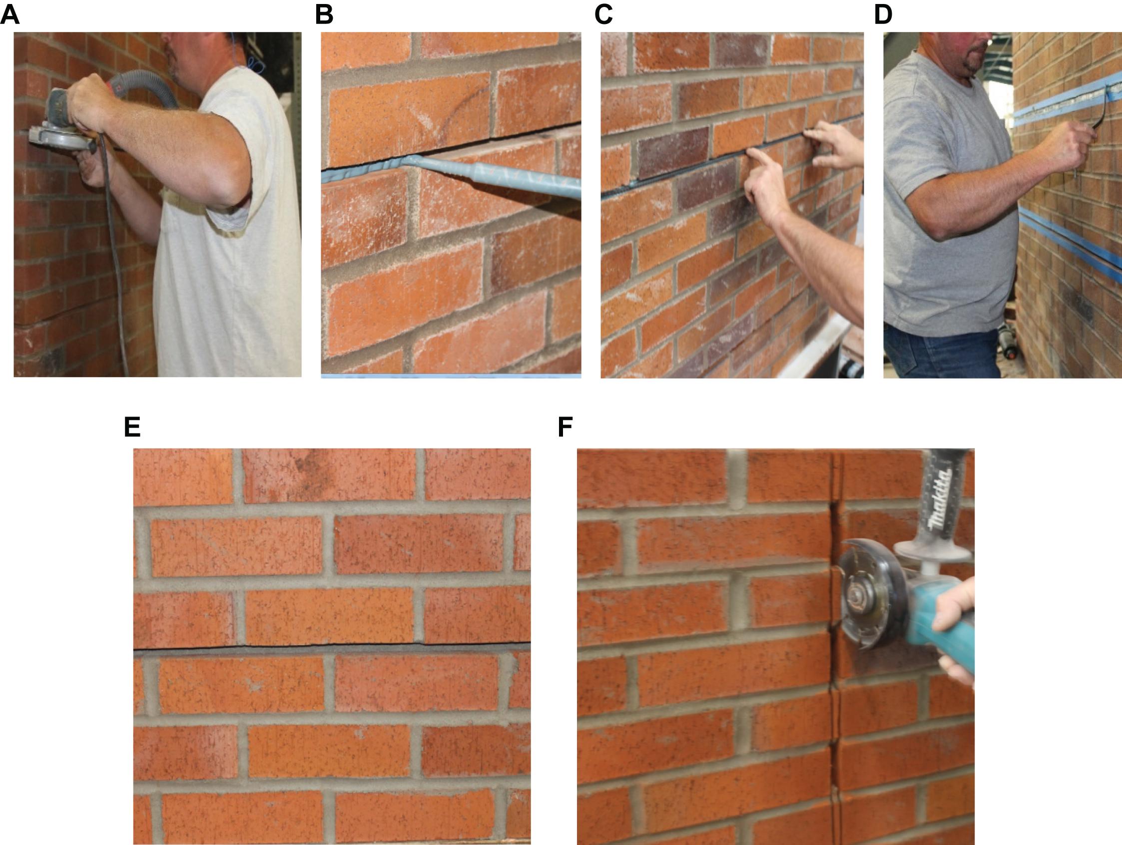
Figure 1. Retrofit steps: (A) saw cutting grooves, (B) partial filling of grooves with epoxy, (C) placing and pressing steel reinforcing bars into the groves with the first layer of epoxy, and (D) filling and surface finishing of grooves, (E) horizontal cut through the bed joint, and (F) vertical cut through the bricks and the head joints.
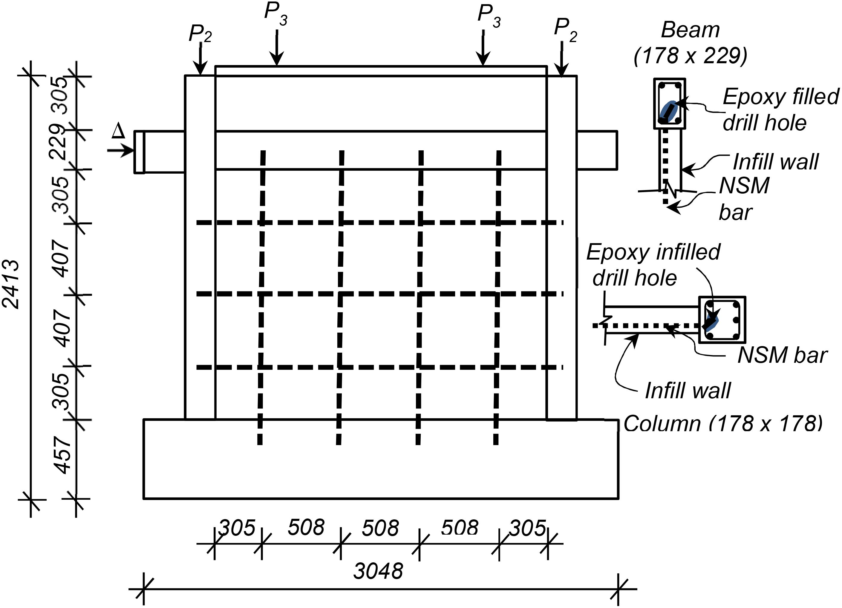
Figure 2. Retrofitting details for one-bay frame retrofitted with three horizontal and four vertical bars. The non-retrofitted model represents Specimen 9 in Mehrabi et al. (1994). NSM reinforcing bars are shown in dashed lines. Arrows represent the load on columns and wall, respectively, which were applied during the testing. Delta (Δ) represents a displacement controlled monotonic or cyclic loading. All dimensions in mm.
The NSM bars are surrounded by the epoxy preventing the bars from being corroded. Additionally, the use of stainless steel or epoxy coated NSM bars can mitigate this risk. Nonetheless, further research on the long-term performance of the system is warranted.
In this study reinforcing bars with diameter of 10 mm (0.375 in.) are embedded into the epoxied grooves (see Figure 1C). The size of reinforcement fits into the typical width of mortar joint [12 mm (0.5 in.)]. Hence the width of a groove cut corresponds to the width of mortar joint. The recommended depth of a groove cut is limited to 25 mm [1 in.] for practical reasons. An anchorage length of 127 mm [5 in.] in the RC beams and columns is also used here. This can be achieved by drilling holes which are filled with epoxy (Figure 2). In the case of intersecting vertical and horizontal bars, the groove layout and NSM reinforcing steel bars can be arranged as shown in Figure 3. It is worth mentioning that the embedment of NSM reinforcing steel bars to the reinforced concrete frames may be challenging in some site conditions and should be assessed carefully while designing the NSM retrofit solutions.
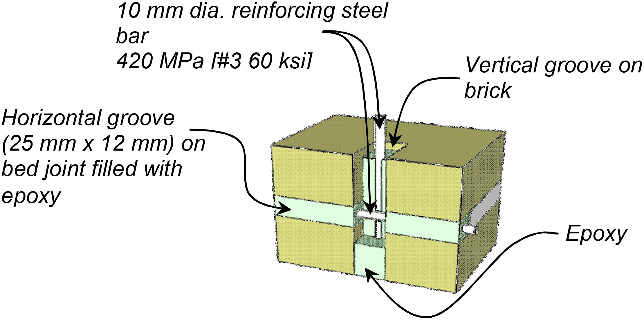
Figure 3. Near-surface mounted reinforcing steel bars placed into pre-cut grooves.
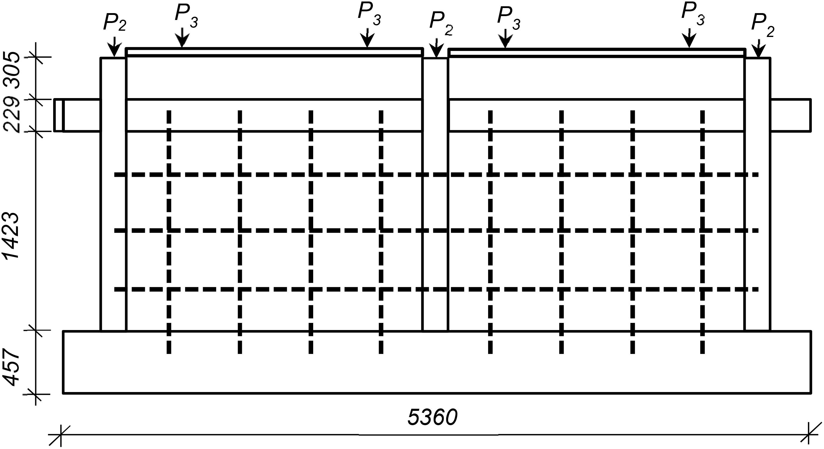
Figure 4. Retrofit of the two-bay frame using three horizontal and four vertical NSM bars on each bay (2BR3H4V). Dimensions are in mm.
The NSM retrofit is intended to be applied on the exterior face of the buildings. The single face retrofit can result in eccentric behavior as discussed in Soti and Barbosa (2019) when a planar wall/frame is considered. Nonetheless, in an actual building, the effect of this eccentricity would be minimized because of the presence of orthogonal walls and connection to bounding columns.
The adopted modeling scheme is expanded, as discussed in subsequent sections, to incorporate the horizontal and vertical bars added to the infill according to the proposed retrofit scheme. The bars are equally spaced and positioned to resist the diagonal shear crack which dominated the failure pattern of the test structure. The calibration of the model is based on the pull-out tests conducted initially. The analysis conducted here consider in-plane vertical and lateral loads. Hence, provide resistance to out-of-plane loads, which the NSM bars can provide, is not considered here. The retrofit strategies considered for the first numerical example are shown in Figures 2, 5, 6. Figure 5 illustrates cases with varying number of horizontal bars in each bay and Figure 6 illustrates cases with varying number of vertical bars in each bay. The load on columns and wall in Figures 5, 6 corresponds to specimen 9 in Mehrabi et al. (1994). The retrofit strategy which combines both horizontal and vertical bars in single-bay frame is shown in Figure 2.
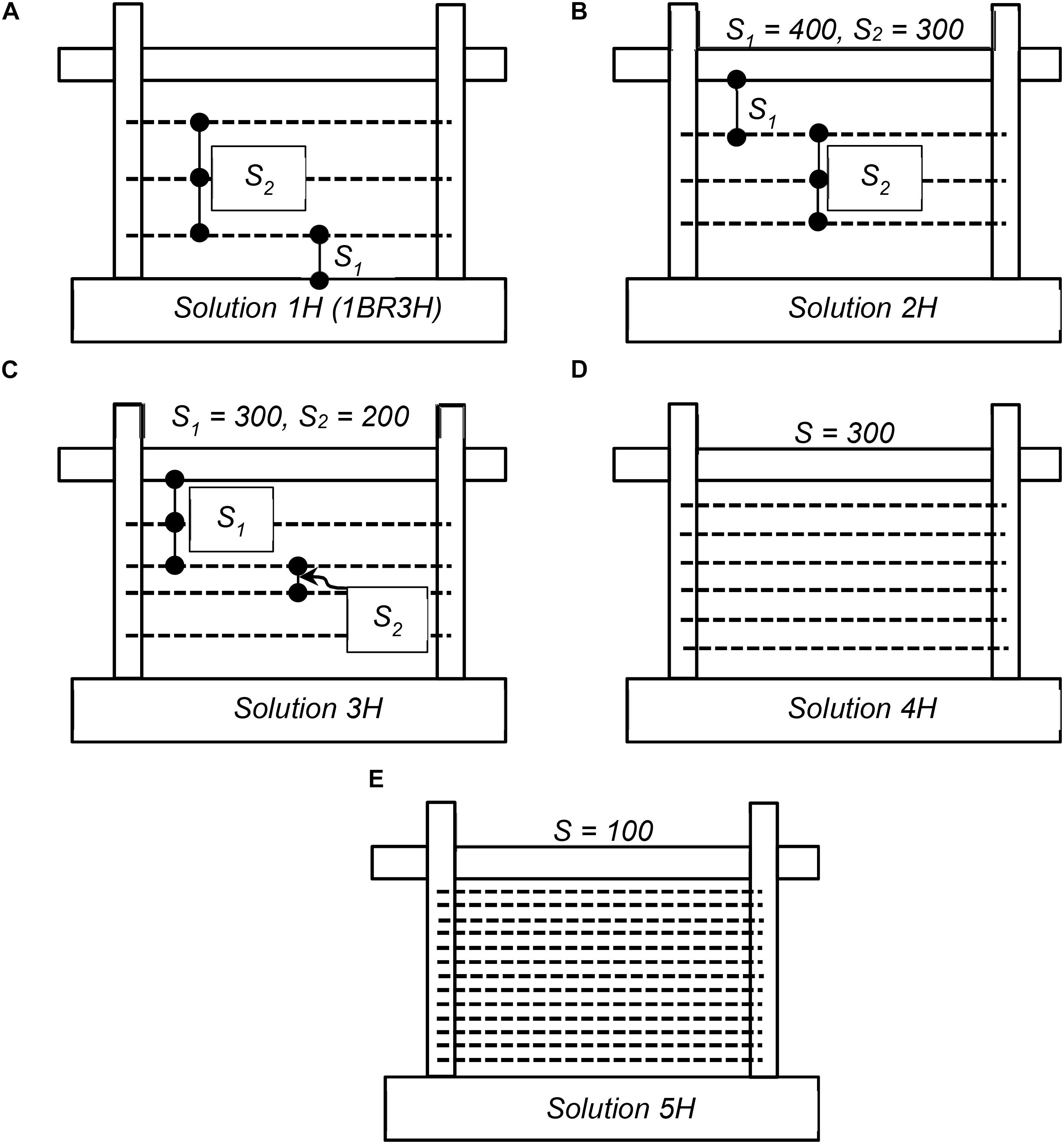
Figure 5. Retrofit solutions with horizontal NSM bars: (A) solution 1H (1BR3H), (B) solution 2H, (C) solution 3H, (D) solution 4H, and (E) solution 5H.
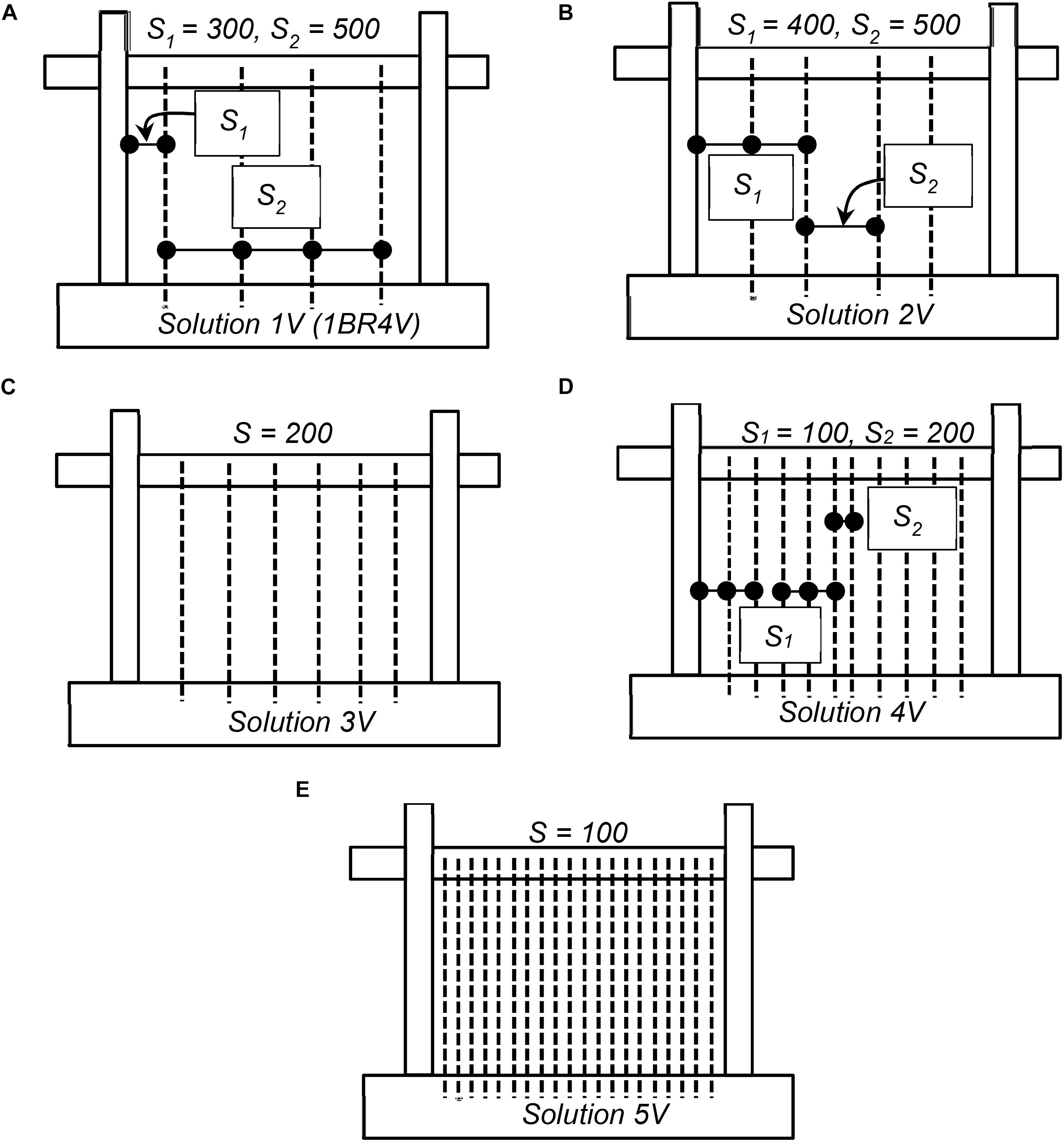
Figure 6. Retrofit solutions with vertical NSM bars: (A) solution 1V (1BR4V), (B) solution 2V, (C) solution 3V, (D) solution 4V, and (E) solution 5V.
Pull-Out Tests
Test Setup and Instrumentation
Pull-out tests were conducted at the Structural Engineering Research Laboratory at Oregon State University to explore the feasibility of the attachment of NSM bars on the surface of the masonry infill and study the bond behavior of the NSM reinforcing steel bars to the infill walls. Two brick walls, as illustrated in Figure 7, were used to test the effectiveness of horizontal and vertical NSM solutions. For both walls, a reinforcing steel bar was anchored in the grooves using epoxy resin over an anchorage length of 203 mm [8 in.], which is approximately equal to the length of a brick. The specimens were built with solid clay bricks of nominal dimensions 193 mm × 92 mm × 57 mm [7.625 in. × 3.625 in. × 2.25 in.] and Type-N mortar in accordance with ASTM C270 (ASTM, 2014). An average flow of the mortar was measured to be 203 mm following ASTM C1437 (ASTM, 2013) during the construction of the test specimens. The average 28-day compressive strength of 50.8 mm × 50.8 mm [2 in. × 2 in.] mortar cubes was 8.5 MPa [1.23 ksi] [ASTM C109 (ASTM, 2016)]. The reinforcing steel bars used were ASTM A615 (ASTM, 2020) Grade 420 [Grade 60] with a diameter of 10 mm (3/8 in.), which is #10M [#3], and measured yield strength of 506.8 MPa (73.5 ksi) based on coupon tests [ASTM A370 (ASTM, 2017)].
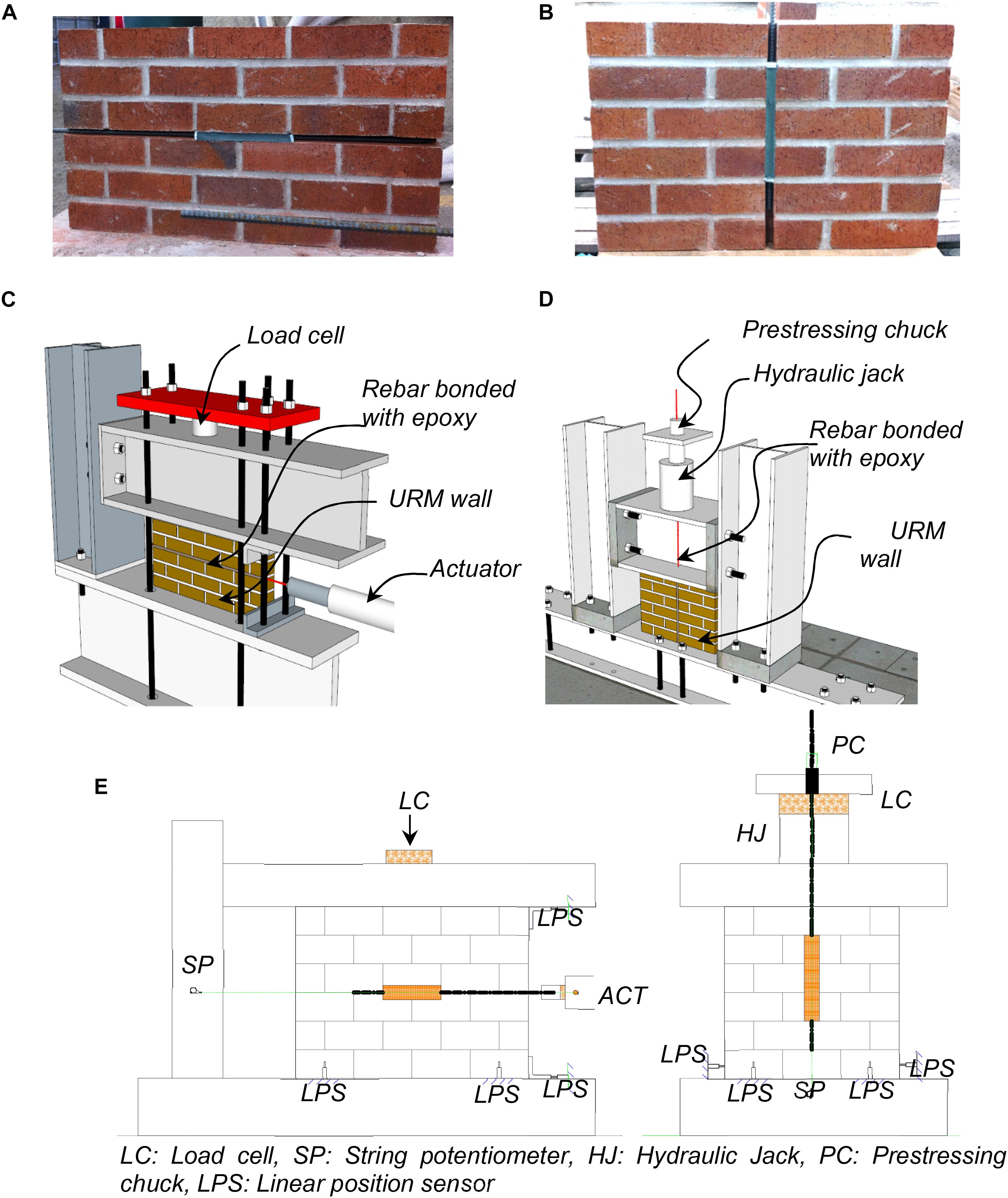
Figure 7. Pull-out tests: (A) horizontal bar pull-out test specimen, (B) vertical bar-pull-out test specimen, (C) horizontal bar pull-out test setup, (D) vertical bar pull-out test setup, and (E) sensor layout for horizontal and vertical NSM reinforcing steel bars.
In the first specimen (Figure 7A), a bar placed horizontally along the mortar joints was pulled by a hydraulic actuator with a maximum capacity of 222 kN (50 kips) and stroke of ± 152 mm (±6 in.), as illustrated in Figures 7C,E. The bar had a threaded tip for load transfer to the actuator. In the second specimen (Figure 7B), the vertical bar was pulled using a hollow hydraulic jack and a prestressing chuck, as shown in Figures 7D,E. The hydraulic jack was mounted on top of the steel beam that was rested on the brick wall. A hollow load cell was attached to the jack, and the vertical bar was passed through the aligned holes of a custom drilled steel beam, hydraulic jack, and load cell. A prestressing chuck with cap and spring (designed for gripping #10M [#3] bars) was used to grip the vertical bar during testing. Tests were executed under displacement control and the loading rate was 0.2 mm/min.
The instrumentation plan used in the pull-out tests is shown in Figure 7E. Each specimen was instrumented with LX-PA 254 mm (10 in.) string potentiometers and 19 mm (0.75 in.) displacement transducers connected to a National Instruments data acquisition (DAQ) system (National Instruments, 1998). The string potentiometer (SP) was used to monitor the displacements of the NSM reinforcing steel bars. Linear positioning sensors (LPS) were used to monitor the sliding and rotation of the walls.
Test Results
The results from the pullout tests are summarized in Figures 8A,B. From the figures it can be seen that a strong connection was established between the bars and masonry walls so that the former reached their yield strain with the prescribed 203 mm long epoxy bond length. In this specimen, bricks close to the far end of the epoxy cracked as shown in Figure 8C, resulting in a sudden drop in the force-deformation curve at approximately 1 mm of deformation. This crack propagated in the vertical direction, perpendicular to the bar direction, and extended into the bricks at approximately 2.0 mm of actuator displacement. In fact, the bar placed vertically developed a higher strength and reached a larger displacement before eventually pulling out. That is probably caused by the stronger connection of the bars when the groove went through the solid bricks (Figure 7B). The bar ultimately slipped, accompanied by brick cracking along the bond length, followed by debonding failure of the epoxy resin as shown in Figure 8D. These test results indicate that the strength of the connection between the masonry wall and the NSM bars over a relatively short length is sufficient to ensure yielding of the bar. Hence, the tests provide a proof of feasibility and confidence in the proposed methodology. Moreover, they provide data which is used in this study for the calibration of the numerical model.
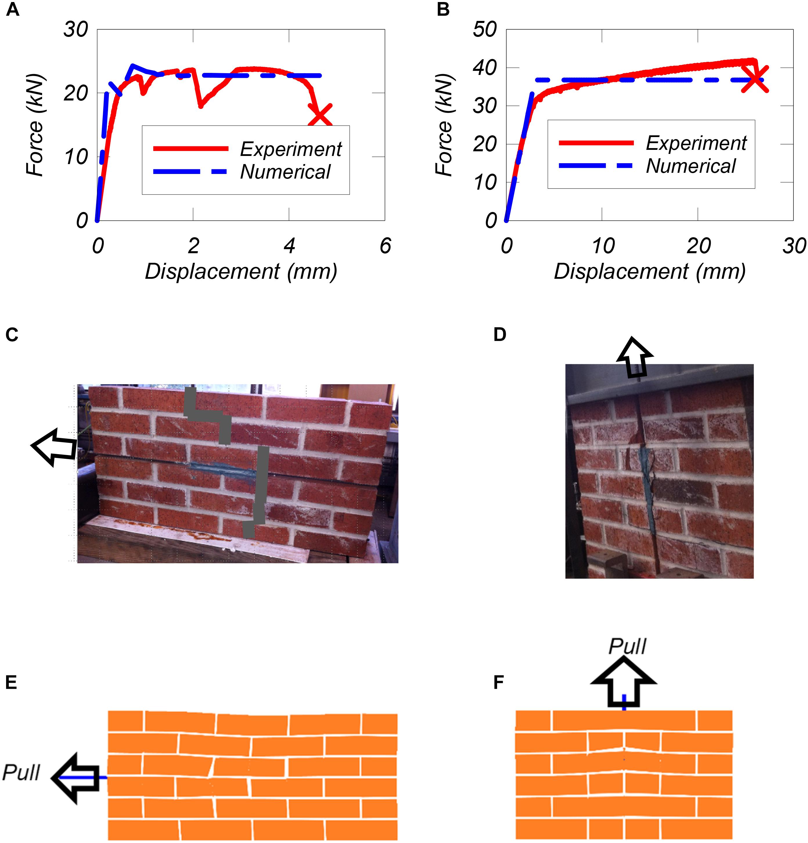
Figure 8. Model validation: (A) load-displacement curves for horizontal bar pull-out, (B) load-displacement curves for vertical bar pull-out, (C) observed cracking patterns of horizontal bar pull-out, (D) observed cracking patterns of vertical bar pull-out, (E) numerical deformed shape for horizontal bar pull-out, and (F) numerical deformed shape for vertical bar pull-out.
Numerical Modeling
Modeling Scheme
To model the seismic behavior of RC frames with infilled masonry, one can use advanced continuum micro-models such as the ones developed in Lourenco et al. (1998), Milani et al. (2006), Lemos (2007), and Stavridis and Shing (2010). The modeling scheme proposed by Stavridis and Shing (2010), which adopts a modeling scheme that combines continuum smeared-crack elements, developed by Lotfi and Shing (1991), with interface elements (Lotfi and Shing, 1994), is used here.
Figure 9 illustrates the modeling scheme developed by Stavridis and Shing (2010) for the RC members and infill. RC members are discretized in modules of four triangular smeared-crack elements connected with four interface elements placed at angles close to 45 degrees. Each module of four triangular smeared-crack elements is connected to other modules through horizontal and vertical interface elements. The interface elements capture horizontal, vertical, and diagonal cracks in a discrete manner. The reinforcing steel bars in the concrete members are modeled with elasto-plastic truss elements. The flexural steel at each location is divided into eight truss elements at each interior location and four truss elements along external edges. The shear reinforcement is divided into two bars placed in a zig-zag pattern as proposed by Stavridis (2009).
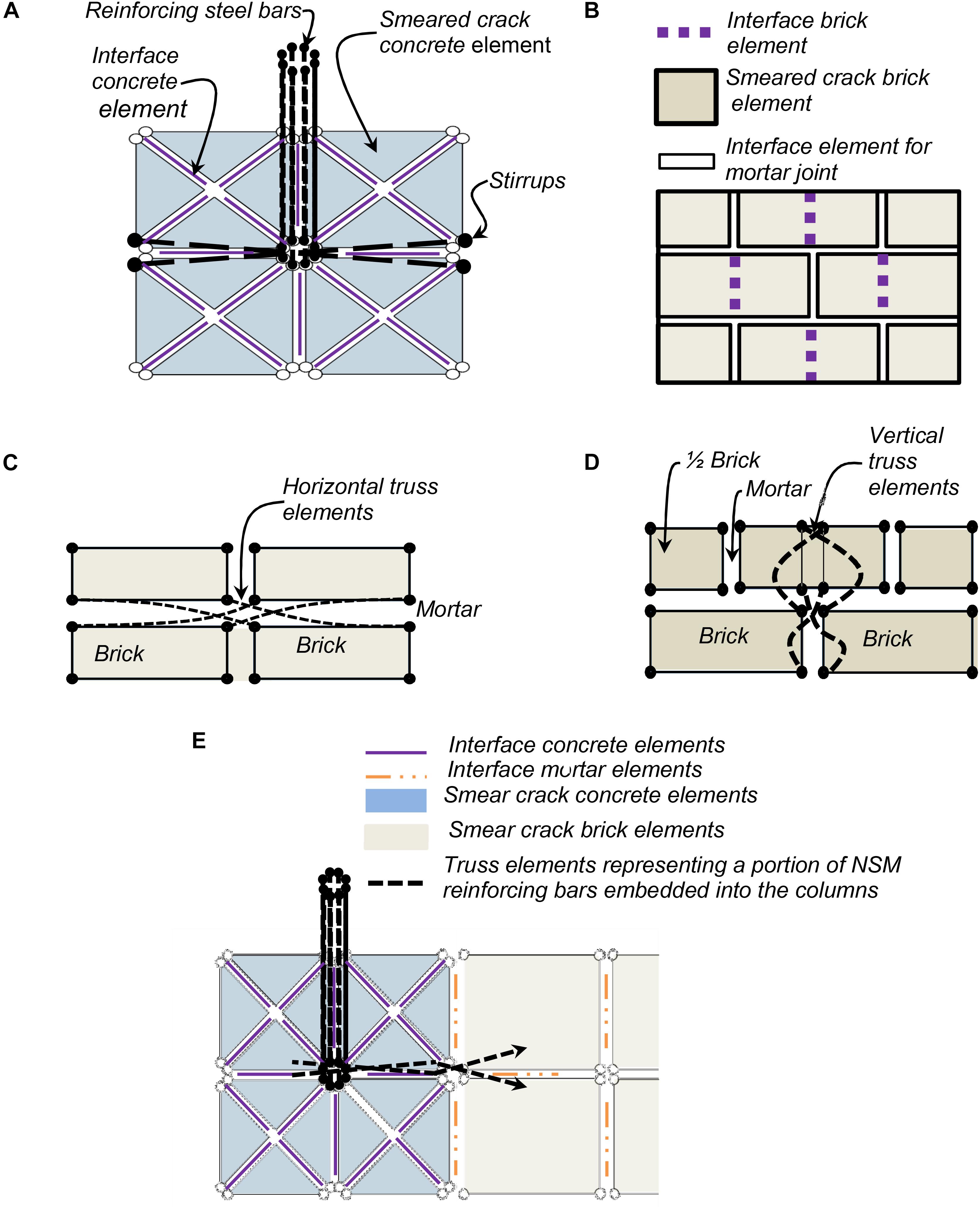
Figure 9. FEM discretization: (A) RC section, (B) URM wall, (C) horizontal near-surface mounted (NSM) reinforcing bar (D) vertical NSM bars, and (E) NSM bars embedded into the concrete column.
The modeling of a masonry unit is illustrated in Figure 9B. The units are modeled with two rectangular continuum elements interconnected with a vertical interface element. The vertical interface element captures tensile splitting and relative rotation of the fractured masonry unit. Mortar joints are modeled with zero-thickness four-noded cohesive-crack interface elements.
The smeared-crack and discrete-crack element formulations used here are proposed by Stavridis and Shing (2010) and are implemented in the Finite Element Analysis Program (FEAP) developed by Taylor (2013). In this formulation, the uncracked concrete or brick elements are modeled with a plasticity model governed by a von Mises failure criterion combined with a tension cutoff. When the von Mises failure criterion is reached, an associated flow rule is used to compute the plastic strains. On the other hand, when the tension cutoff criterion is reached, a crack is formed, and the material model adopts an orthotropic material law to simulate the nonlinear behavior of the material in tension and compression. The direction of the cracks is fixed and normal to the direction of the maximum principal stresses.
The constitutive model used in the interface elements considers the contraction of the yield surface, defined by a hyperbolic yield criterion governed by the tensile strength of the interface, the radius of the yield surface at the vertex of the hyperbola, and the slope of the asymptotes. In addition, the constitutive relation adopts a non-associated flow rule to allow the scaling of the shear dilatancy. Thus, the interface elements can simulate mode-I, mode-II, and mixed-mode fracture of the discrete cracks in the RC members and masonry panels.
The NSM reinforcing steel bars used in the retrofitting solution are modeled as elastoplastic truss elements. Each reinforcing bar is split into four truss elements that connect the nodes of the continuum brick elements, as shown in Figures 9C,D. These truss elements are connected in a zig-zag cross pattern, similar to the one used for the shear reinforcement in the RC members (Figure 9A), along the interface elements simulating the mortar joints or the brick interface elements. This modeling scheme assumes that the connection of the NSM bars to the masonry infill will not fail, allowing the NSM bars to yield. This assumption is justified by the pull-out tests discussed in a previous section.
Similar to the embedment in the masonry walls, the embedded portion of the NSM reinforcing steel bars into the columns is modeled using zig-zag truss elements that connect the brick wall and the concrete columns, as shown in Figure 9E. Thus, the possible dowel action of the inclined embedded bar into the column has not been explicitly accounted for in this study. This is deemed acceptable since a previous study indicates that the addition of the dowel connections to the columns results in a minimal strength increase (Redmond et al., 2016).
NSM Numerical Modeling Validation
The modeling scheme for the NSM bars is first used here to model the pull-out tests discussed in a previous section. The mechanical properties of the materials used in the numerical model are summarized in Table 1. These properties are defined based on material tests conducted by Mehrabi et al. (1994), and the values proposed by Stavridis (2009).
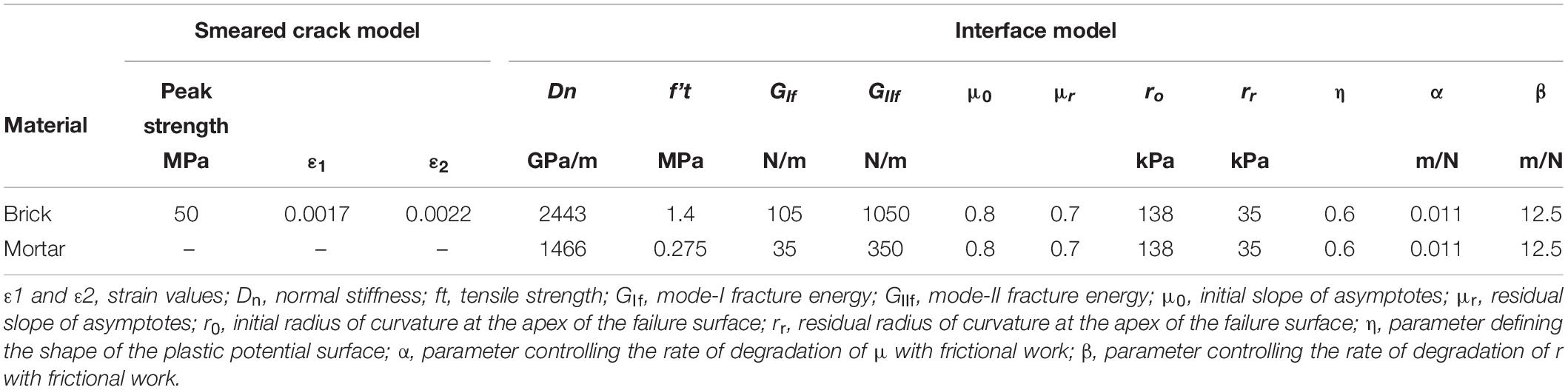
Table 1. Material properties used in the numerical analysis of component tests.
The experimental and numerical results and failure patterns are compared in Figures 8A–D. It can be observed in Figure 8 that the model can capture the initial stiffness, as the error is less than 12% in both cases. The peak load is also captured well for the horizontal bar pull-out test, but not as well for the vertical bar pull-out test. The discrepancy is caused by the hardening of the reinforcing steel bar in the test which is not captured by the numerical model. A different material model which can account for the strain hardening could be implemented and improve the numerical results. Moreover, in both cases, the numerical models do not capture the local brick cracks and associated loss of strength, nor do they capture the final failure observed in the vertical bar pull-out test (Figure 7B). Moreover, the proposed modeling approach does not explicitly capture the slip of the embedded reinforcing steel bar and the deboning of the epoxy from the masonry units. Nonetheless, the modeling approach can capture the response of the NSM retrofit until the initiation of bond failure, which generally occurs at relatively high strains of the NSM bars as evident in De Lorenzis and Teng (2007). Hence, such features are not considered in the modeling scheme to maintain its simplicity.
Overall, despite the identifiable discrepancies between the numerically computed and experimentally measured post-peak behaviors observed in Figure 8, it can be concluded that the adopted modeling approach can predict the overall behavior of the embedded NSM bars with reasonable accuracy for the range of response of interest in the case of infilled RC frames. Moreover, although the tests and simulations in this study consider clay masonry units, it is evident that the methodology can be extended to masonry units of other materials as well as long as the epoxy material is selected to ensure that the reinforcing steel bars yield prior to the debonding. In case such data is not available, this may require small scale pull-out testing such as the ones performed in this study.
Application on Infilled RC Frames
In this section, the effectiveness of the NSM bars on infilled RC frames is investigated. As summarized in Table 2, two prototype structures are considered and the influence of the orientation and number of the NSM bars is varied. These are examined in a parametric study conducted for the single-bay structure and the most effective bar arrangements are identified and applied to the two-bay frame.
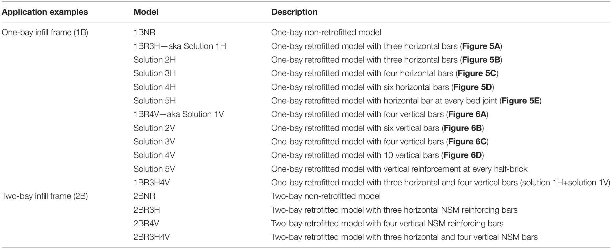
Table 2. Numerical models analyzed.
The model used in these analyses is the model developed by Stavridis and Shing (2010) for Specimen 9 of the tests conducted by Mehrabi et al. (1994). The design and modeling details of the structure can be found in Stavridis (2009), while the comparison of the failure patterns and force-vs.-displacement curves is presented in Figure 10. The RC frame had insufficient shear reinforcement and experienced a brittle failure due to the shear cracks that initiated in the infill and propagated though the columns (Figure 10). This is a typical failure pattern of infilled frames with strong infill and non-ductile frame (Stavridis et al., 2012). The FE model captures both the shear-dominated failure sequence and the important features of the force-vs.-displacement curve and it has been used in other studies that have led to the analytical assessment approach proposed by Stavridis et al. (2017), which is adopted by ASCE 41-17 (ASCE/SEI 41-17, 2017).
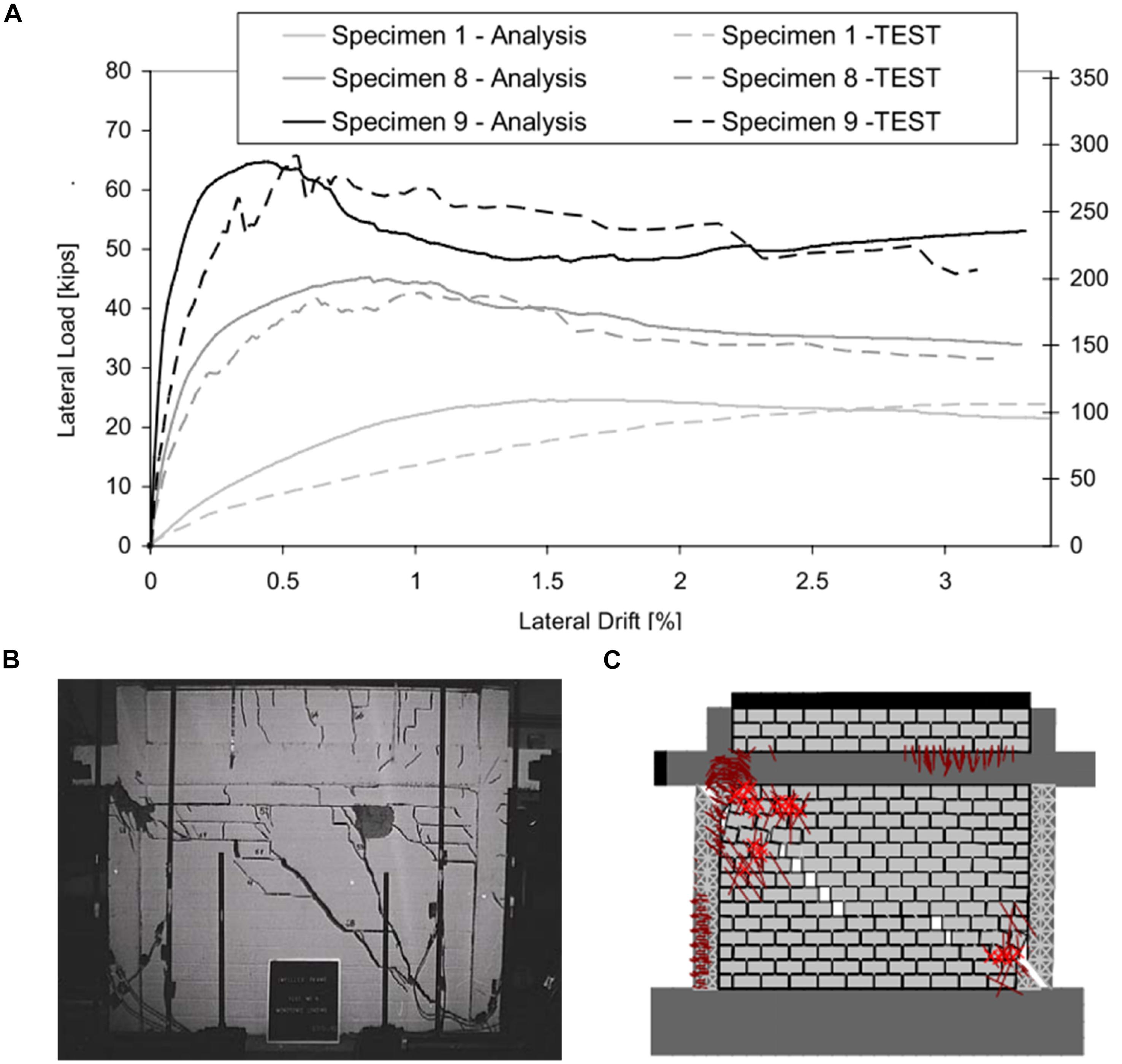
Figure 10. FEM Model validation in Stavridis (2009): (A) Lateral force-vs.-lateral displacement curves, (B) Experimental failure pattern of Specimen 9 at drift of 2.8%, and (C) Deformed shape of model of specimen 9 at drift of 0.46%.
One-Bay (1B) One-Story Frame
A parametric study is conducted to investigate the influence of the quantity and layout of NSM bars on the performance of the infilled RC frame tested by Mehrabi et al. (1994) under in-plane loading. The variations considered in terms of the number and distribution of horizontal and vertical NSM reinforcing steel bars are shown in Figures 5, 6, respectively. As seen in the figures, 10 different configurations of NSM reinforcing steel bars in terms of the number of bars, as well as the spacing between the bars, are investigated, namely (a) Frames 1H through 5H for the horizontal bars, and 1V through 5V for the vertical bars. The different arrangements are summarized in Table 2. Cases 5H and 5V have very small spacing between the bars and do not represent practical options. However, they are considered here as upper bounds of the possible amount of reinforcement that can be added to the infill. The results obtained for these variations are described in the following subsections.
Influence of Horizontal NSM Bars
The first two cases with horizontal bars include solutions 1H and 2H with the same number of bars and different spacing, and then the number of bars increases until the not so practical case of 5H which includes NSM bars in every bed joint. Figure 11A presents the results from the pushover analyses for the horizontal NSM solutions considered. It can be observed that in all cases the strength of the frame, as well as its ductility, increase drastically compared to the non-retrofitted frame (Table 3). However, the peak load of the retrofitted model is not sensitive to the quantity and arrangement of horizontal NSM bars in the infill panel. In fact, the first four cases seem to have rather similar behavior. Case 5H, which has NSM bars in every bed joint and therefore would not be a practical solution, remains almost elastic until 300 kN, while all other frames have an apparent yield strength of around 200 kN. Hence, it reached its peak strength at 0.4% drift ratio and then maintained the same strength as it does not exhibit any strength degradation, as the large number of steel bars yielded.
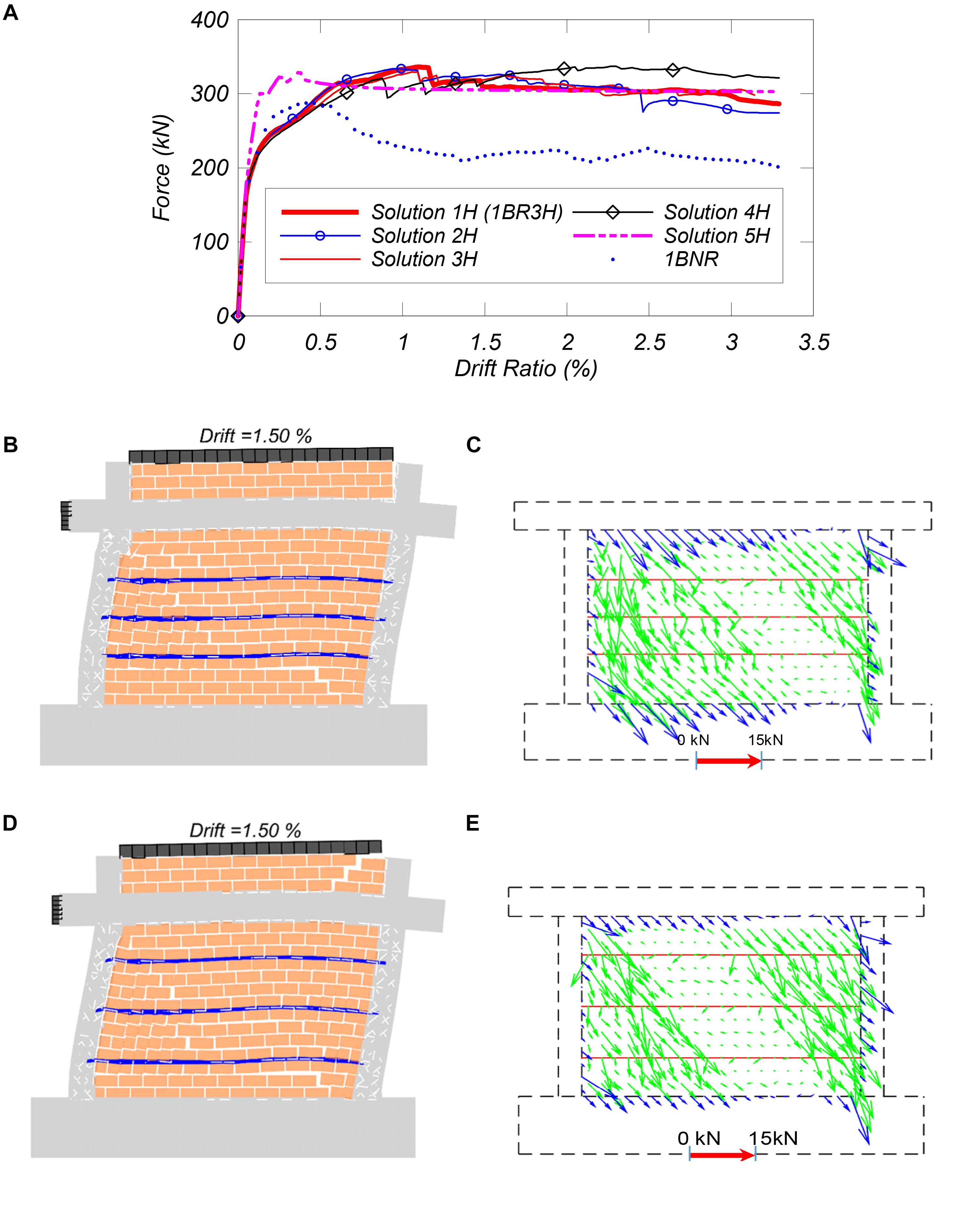
Figure 11. The response of one-bay retrofitted model with a different number of horizontal NSM bars: (A) lateral force vs. drift ratio, (B) deformed shape of Solution 2H, (C) force distribution of Solution 2H (D) deformed shape of 1BR3H, and (E) force distribution of 1BR3H.
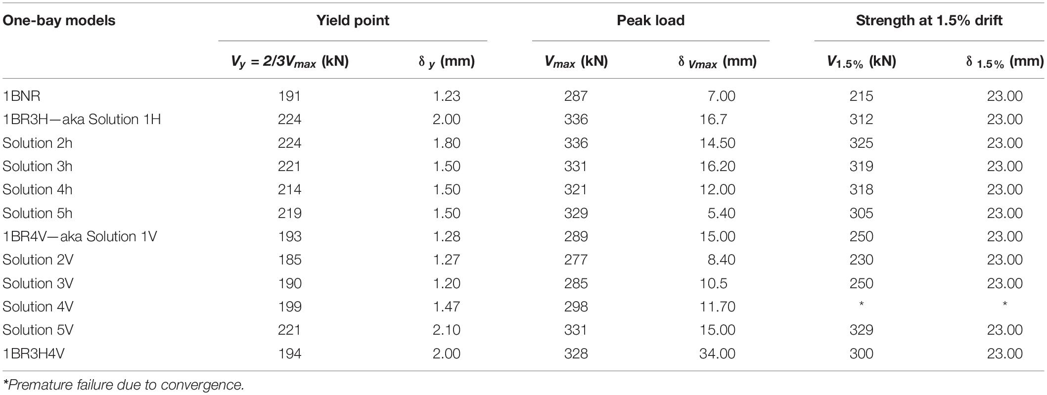
Table 3. Numerical results of non-retrofitted (NR) and retrofitted specimens (one-bay frame).
For the retrofitted models with an equal number of horizontal NSM bars (e.g., frames 1H and 2H), the behavior of the retrofit solution does not depend on the arrangement of the NSM bars in terms of the initial stiffness, peak strength, and failure pattern. Comparing Figures 11C,E, which present the distribution of forces in the infill (green arrows), and along the frame-infill interface (blue arrows) at drift of 1.5%, it can be observed that the bar distribution minimally affects the internal force distributions (Figures 11B,D). Both frames develop a similar failure pattern except the additional diagonal cracks on top of the beam in 1BR3H.
Influence of Vertical NSM Bars
The influence of vertical NSM reinforcing steel bar quantity and distribution on the response of the retrofitted frames to in-plane lateral loading is presented in Figure 12. Solution 5V has vertical NSM reinforcing bars spaced at every half-brick. Cases 1V and 2V include the same amount of reinforcement with different spacing, and the quantity of NSM reinforcing bars increases from cases 2V to 5V, as illustrated in Figure 6.
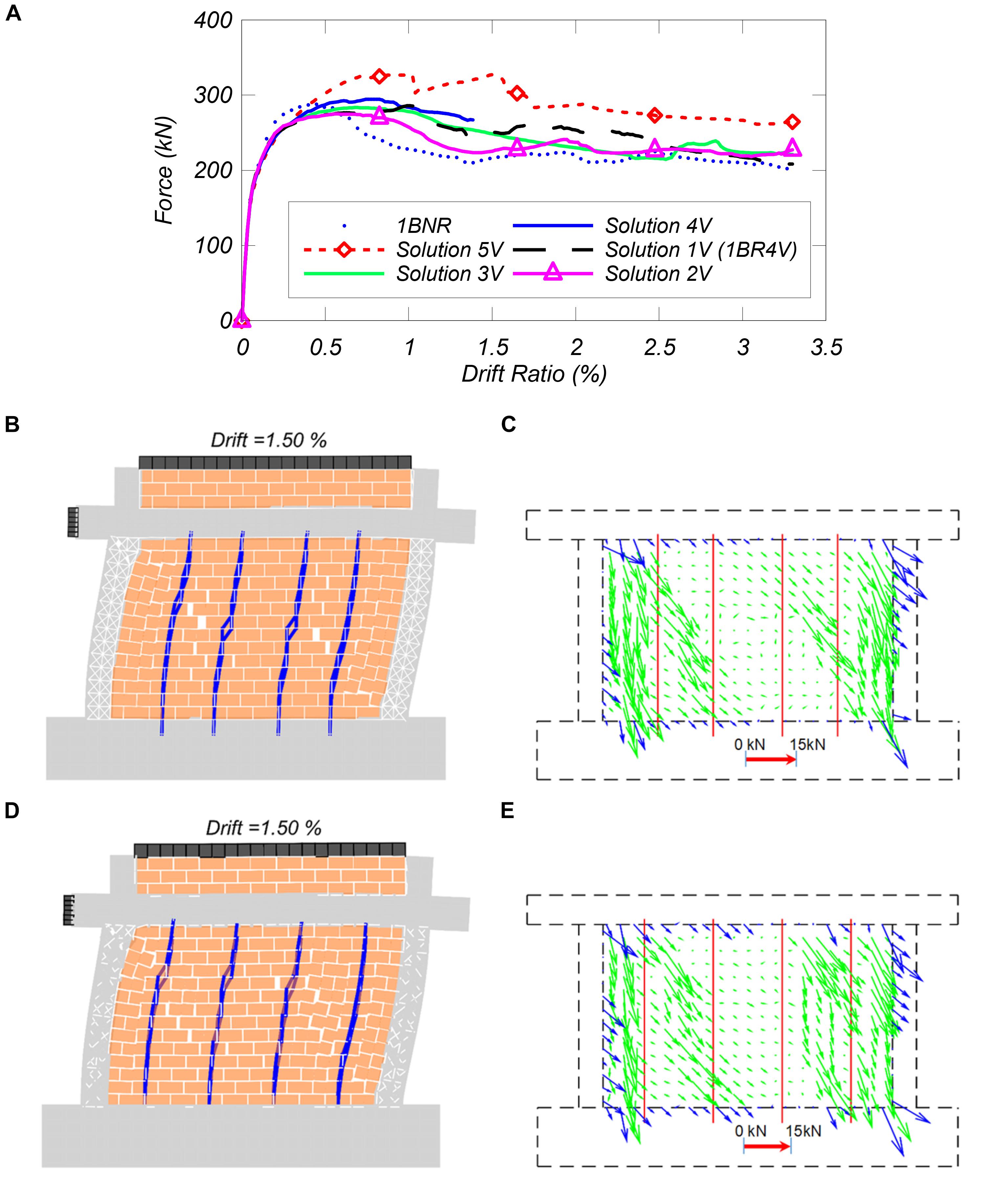
Figure 12. Response of one-bay frame retrofitted with different number of vertical NSM bars: (A) lateral force vs. drift ratio of the models with different retrofit solutions using vertical NSM bars, (B) deformed shape of Solution 2V, (C) force distribution of Solution 2V, (D) deformed shape of 1BR4V, and (E) force distribution of1BR4V.
Figure 12 presents the results for pushover curves for the frames with vertical NSM bars. The results indicate that the peak load increases with the increase in the number of vertical NSM bars. The impractical model 5V seems to have the highest strength, however, the increase does not justify the additional effort and material needed to mount such a large number of bars on the infill. For the retrofitted models with an equal number of vertical NSM bars, 1V and 2V, it can be observed in Figures 12B–E that having vertical bars closest to the columns resulted in higher post-peak lateral shear resistance. However, the difference is not significant on the crack patterns and internal force distribution. For the sake of brevity, the deformed meshes for the other cases are not shown. The main takeaway of the deformed shape results is that as the number of vertical NSM reinforcing steel bars decrease, the failure mode of the infill wall changes from flexural to shear dominated.
Based on the results obtained from the parametric study with the varying number of horizontal and vertical bars, it is evident that adding more than three horizontal bars, or more than four vertical bars does not yield significant improvement of the results. Hence, these configurations are further explored. Figure 9A shows the pushover results in terms of applied force vs. horizontal drift ratio of these cases, as well as the non-retrofitted case.
The model with three horizontal bars reaches a peak load of 331 kN at a drift ratio of 0.98%. The peak load is 16% higher than that of the non-retrofitted model, and the displacement at which the peak load is reached increases by almost 100%; from 0.5 to 0.98%. As the displacement increases, the lateral capacity starts to mildly degrade with the initiation of diagonal cracking and bed joint shear deformation of the infill wall. At 1.5% drift ratio, the shear cracks propagate in the infill wall without the development of shear failure in the columns, as shown in Figure 9C. The model which has four vertical NSM reinforcing bars, shows a maximum shear capacity of 286 kN at 0.98% drift ratio. The peak load of the model does not increase when compared to the non-retrofitted model. However, the peak load is reached by this model at 0.98%, as the model with the three reinforcing bars. However, unlike that model, in the case with the vertical bars, the load drops as the imposed displacement increases due to the presence of vertical grooves that induce a softening behavior in the infill walls under the influence of in-plane loading. This model develops multiple bands of diagonal shear cracks and a plastic hinge at the bottom of the right column, as shown in Figure 12D. Hence, although both NSM bar arrangements improve the performance, adding bars horizontally yields better behavior for the frame.
Frame With Both Vertical and Horizontal NSM Bars
With the optimal number of horizontal and vertical bars investigated in the previous section, the combined effect is investigated in a model that incorporates three horizontal and four vertical bars. This model, illustrated in Figure 13, reaches an apparent yield point at a drift of 0.2% and a load of 220 kN, but its resistance keeps increasing until it reaches a peak load of 328 kN at 2.2% drift ratio. This load is practically sustained until the analysis stops at 3% drift ratio. The capacity increase of 16% unretrofitted and the sustained shear resistance over the wide range of displacements are possible due to the contribution from both horizontal and vertical NSM reinforcing steel bars. In this model, the damage develops mainly in the infill, and it is less severe compared to other NSM retrofit reinforcing steel bar arrangements (Figure 13B). It is worth noting again that dowel action and failure of the reinforcing steel is not modeled, and it can be argued that the results beyond the 1.5% drift ratio are beyond the ability of the model to capture the damage at large level of displacements, as panel tests by Soti and Barbosa (2019) indicate. However, the improvement of the performance of the infilled frame is evident. For the given geometry and boundary conditions, the optimum combination of horizontal and vertical NSM bars needs to be provided to ensure the ductile performance of the infill frame.
Figure 13. Response of the one-bay retrofitted solutions tested: (A) lateral force vs. drift ratio curves of the one-bay frame, (B) deformed shapes at 1.5 percent drift ratio for the one-bay non-retrofitted example, and (C) deformed shape of one-bay example retrofitted with 3H4V.
Two-Bay Frame
The analyses and experiments reported by Stavridis (2009) indicate that the failure patterns of infilled RC frames can change between single-bay and multi-bay infilled frames. Hence, a two-bay frame model that is an extension of the one-bay frame model discussed in the previous section (Figure 8) is also considered in this study. The frame has the same geometry, reinforcing details, material properties, and loads. The three most efficient retrofit arrangements considered for the single-bay frame are considered for the two-bay frame as well: a model retrofitted with three horizontal bars (2BR3H), a model retrofitted with four vertical bars per infill panel (2BR4V), and a model combining three horizontal and four vertical NSM reinforcing bars per panel (2BR3H4V), which is shown in Figure 4.
The results for the pushover analyses of the two-bay models are shown in Figure 14 and summarized in Table 4. In Figure 14A, the non-retrofitted, reference model shows a first peak load of 500 kN at a drift ratio of 0.5%. With increasing imposed displacements, the shear capacity first decreases, but then increases to the maximum shear capacity of 525 kN at 1.3% drift ratio. At 2% drift ratio, the shear capacity drops drastically due to shear failure of the infill wall panels as shown in Figure 14B. At 2.5% drift ratio, the two-end columns develops shear failures, while the central column displays a bending failure with hinges forming at the top and bottom of the column.
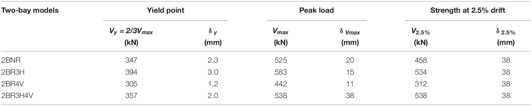
Table 4. Numerical results of two-bay frame models.
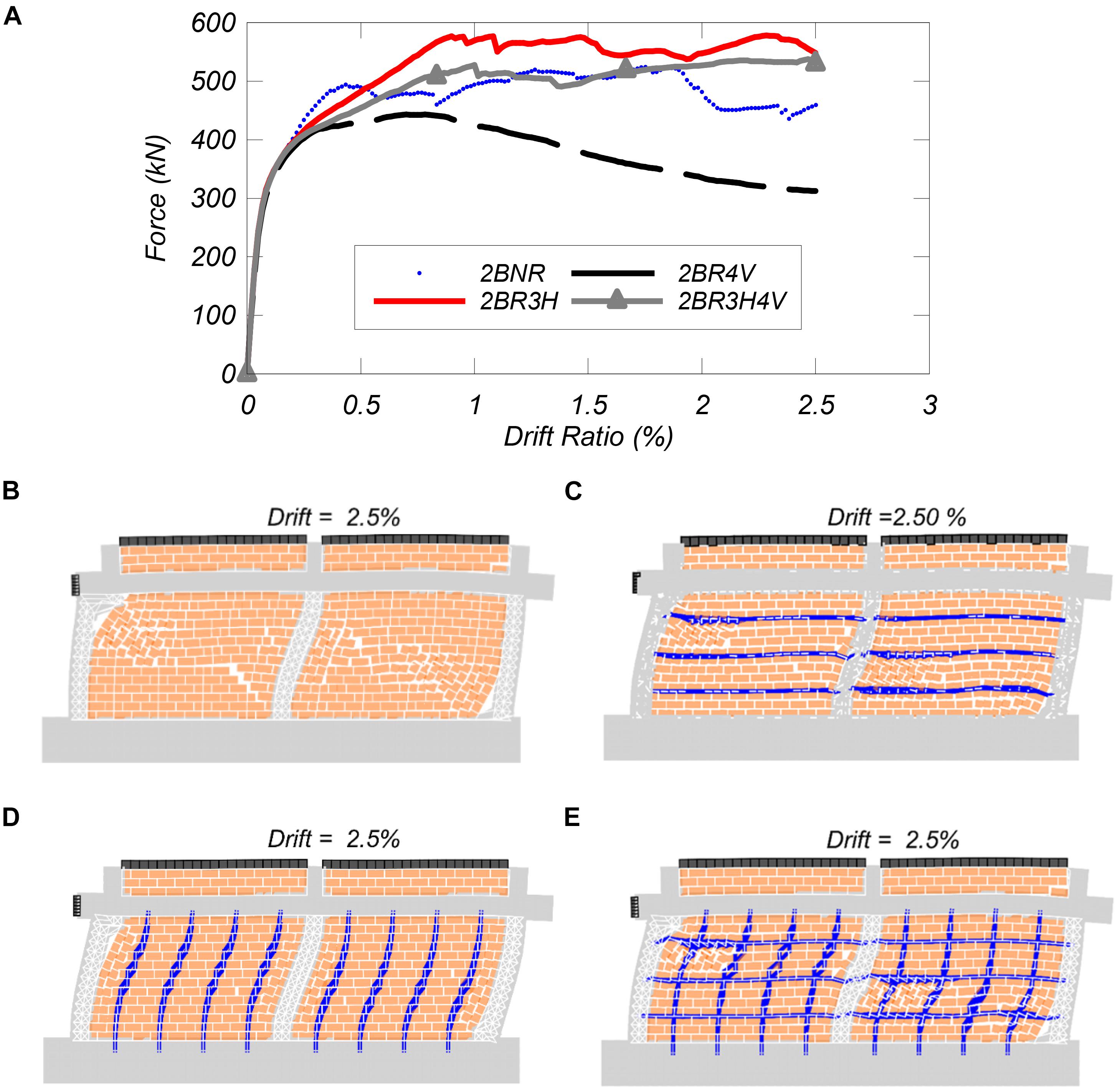
Figure 14. Response of two-bay frame: (A) lateral force vs. drift ratio for two bay frame, deformed shapes at 2.5 percent drift ratio for: (B) 2BNR, (C) 2BR3H, (D) 2BR4V, and (E) 2BR3H4V.
The retrofitted model with three horizontal bars reaches a peak load of 583 kN at approximately 1.00% drift ratio (Figure 14A). Upon further increase of the drift, the shear capacity gradually goes down to reach 534 kN at 2.5% drift ratio. The failure mode for this frame is similar to the unretrofitted frame except in the central column where a shear failure is also observed at mid-height of the column (Figure 14C).
The retrofitted model with only vertical NSM reinforcing bars (2BR4V) achieves a peak load of only 442 kN at 0.72% drift ratio. With a further increase in drift, this model shows a steady loss of capacity. The failure mode associated with this model, as shown in Figure 14D; involves mainly a shear failure of end columns, flexural deformation of the middle column, and sliding in the infill panels.
Finally, the retrofitted model with three horizontal and four vertical NSM reinforcing bars reaches a peak load of 574 kN at 2.5% drift ratio. This model develops shear failures in all three columns and infill wall panels (Figure 14E).
As in the single-bay frame, the infill shear resistance of the two-bay frame reduces when retrofitted with only four vertical bars. The difference is 6% for the single bay frame, but it drops by 33% in the case of the two-bay frame. The higher reduction of the infill shear resistance in the latter frame can be attributed to an early diagonal cracking that is developed when the vertical reinforcement prevents the uplift of the wall. Thus, the contribution of vertical reinforcement to the lateral strength of the infill frame is not straightforward. The infill walls where only vertical reinforcement is added can lead to a reduction on the lateral strength of the infill frame due to the reduced cross sections in the locations of the NSM bars, but also due to the possible diagonal cracking of infill as shown in Figures 12D, 14D.
When only horizontal reinforcement is added, as in the case of the single bay frame, the lateral strength increases considerably. When compared to the vertical reinforcement, the horizontal reinforcement provides a higher ductility. In both frames, however, the largest ductility improvement can be observed when horizontal reinforcement is combined with vertical reinforcement.
Conclusions
A retrofit solution for URM infilled RC frames that involves the use of NSM reinforcing steel bars is proposed in this paper. The feasibility of the proposed solution is examined initially with a series of pull-out tests on NSM bars attached to masonry panels. These tests indicate that NSM bars can yield in tension before the bond between the bars and masonry wall fails when the bars are placed in groves along the bed or head joints. The results from the pull-out tests are used to calibrate a 2D non-linear finite element modeling approach which is used to assess the effectiveness of the proposed retrofit solution.
The modeling approach combines discrete and smeared-crack elements and it is extended here to simulate the effect of the addition of NSM bars on an experimentally tested single-bay infilled RC frame which failed in shear. Ten different configurations with varying number of horizontal or vertical reinforcement are considered. From the results obtained, it can be seen that in most cases, the NSM bars can alleviate the brittle failure patterns. Interestingly, the peak load and ductility of the retrofitted models is not sensitive to the quantity of horizontal NSM bars in the infill panel for the cases considered here. However, the higher number horizontal NSM bars induce brittle failures of RC frame members. In terms of the vertical bars, the peak load increases with the increase in the number of vertical NSM bars.
Based on the results, the retrofit schemes with three horizontal and four vertical bars are considered the most viable, and when combined result in the highest strength and ductility. The effectiveness of this scheme with both vertical and horizontal bars is confirmed when a two-bay frame is considered.
When compared to the non-retrofitted model, the one-bay model retrofitted with three horizontal and four vertical bars reaches 14% higher strength at approximately five times higher displacement, demonstrating significantly more ductile behavior. Also, noteworthy, the displacement at the peak load of the two-bay retrofitted model is almost double of that of the non-retrofitted model, whereas the peak load is only 2.5% higher than that of non-retrofitted model. Hence, considering the increase in strength, and the ease of application, the retrofit scheme with horizontal bars I recommended here.
Over-reinforcing the infill may result in a brittle failure mode for the bounding columns. The optimum quantity of the horizontal and vertical NSM bars should be designed to achieve ductile performance of the infilled frame.
The tests demonstrate the feasibility of this retrofit solution, while the numerical results demonstrate promising potential in the use of NSM reinforcing steel bars for retrofitting URM infilled RC frames under in-plane loading. However, it is suggested that additional testing on infilled RC frames be performed to further explore the performance of this retrofit solution under in-plane and out-of-plane seismic loads. In addition, the development of a reliable design methodology is warranted in future studies for the retrofit solution to be adopted by practicing engineers.
Data Availability Statement
The raw data supporting the conclusions of this article will be made available by the authors, without undue reservation, to any qualified researcher.
Author Contributions
RS, AB, and AS: conceptualization, methodology, and documentation. RS and AB: testing. AS: software. RS: visualization and graph. AB: funding acquisition. All authors contributed to the article and approved the submitted version.
Conflict of Interest
RS was employed by Jacobs Engineering.
The remaining authors declare that the research was conducted in the absence of any commercial or financial relationships that could be construed as a potential conflict of interest.
Funding
The research was funded by the Cascadia Lifelines Program (CliP) and additional funding was provided by Bonneville Power Administration (BPA) for the component testing. The work was also supported by the National Science Foundation Grant Nos. CMMI−1545632 and 1545595.
Acknowledgments
We are grateful to Mutual materials for donating bricks and mortar. International Masonry Institute provided the epoxy, and their support is also acknowledged. However, the opinions and conclusions presented in this manuscript are those of the authors and do not necessarily reflect the views of the sponsoring organizations.
References
ASCE/SEI 41-17 (2017). Seismic rehabilitation and retrofit of existing buildings. Reston, VA: American Society of Civil Engineers.
ASTM (2013). Standard Test Method for Flow of Hydraulic Cement Mortar. ASTM C1437-13. West Conshohocken, PA: ASTM.
ASTM (2014). Standard Specifications for Mortar for Unit Masonry, ASTM C270-14a. West Conshohocken, PA: ASTM.
ASTM (2016). Standard Test Method for Compressive Strength of Hydraulic Cement Mortar (Using 2-in. or [50-mm] Cube Specimens). ASTM C109-16a. West Conshohocken, PA: ASTM.
ASTM (2017). Standard Test Methods and Definitions for Mechanical Testing of Steel Products. ASTM A370-17. West Conshohocken, PA: ASTM.
ASTM (2020). Standard Specification for Deformed and Plain Carbon-Steel Bars for Concrete Reinforcement. ASTM A615/A615M – 20. West Conshohocken, PA: ASTM.
Baboux, M., and Jirsa, J. O. (1990). Bracing System for Seismic Retrofitting. J. Struct. Engine. ASCE 116, 55–74. doi: 10.1061/(asce)0733-9445(1990)116:1(55)
Barbosa, A. R., Fahnestock, L. A., Fick, D. R., Gautam, D., Soti, R., Wood, R., et al. (2017). Performance of Medium-to-High Rise Reinforced Concrete Frame Buildings with Masonry Infill in the 2015 Gorkha, Nepal, Earthquake. Earthquake Spectra 33, S197–S218.
Bolis, V., Stavridis, A., and Preti, M. (2017). Numerical Investigation of the In-plane Performance of Masonry-infilled RC Frames with Sliding Subpanels. J. Struct. Engine. 143:04016168. doi: 10.1061/(asce)st.1943-541x.0001651
De Lorenzis, L., and Teng, J. G. (2007). Near-surface mounted FRP reinforcement: An emerging technique for strengthening structurs. Composites Part B Engine. 38, 119–143. doi: 10.1016/j.compositesb.2006.08.003
De Lorenzis, L., Tinazzi, D., and Nanni, A. (2000). “Near-Surface Mounted FRP Rods for Masonry Strengthening: Bond and Flexural Testing,” in Proceedings of the Meccanica Delle Strutt Muratura Rinforzate Con FRP Materials Symposium, (Venezia: ICEE).
Dizhur, D., Giaretton, M., Giongo, I., and Ingham, J. (2017). Seismic retrofit of masonry walls using timber strong-backs. Struct. Engine. Soc. J. SESOC 30, 30–44.
Dizhur, D., Griffith, M., and Ingham, J. (2014). Out-of-plane strengthening of unreinforced masonry walls using near surface mounted fibre reinforced polymer strips. Engine. Struct. 59, 330–343. doi: 10.1016/j.engstruct.2013.10.026
ElGawady, M., Lestuzzi, P., and Badoux, M. (2006). “Retrofitting of masonry walls using shotcrete,” in 2006 NZSEE Conference. (New Zealand: NZSEE), 45–54.
Formisano, A., Castaldo, C., and Chiumiento, G. (2017). Optimal seismic upgrading of a reinforced concrete school building with metal-based devices using an efficient multi-criteria decision-making method. Struct. Infrastruct. Engine. 13, 1373–1389. doi: 10.1080/15732479.2016.1268174
Formisano, A., Lombardi, L., and Mazzolani, F. M. (2016). Perforated metal shear panels as bracing devices of seismic-resistant structures. J. Construct. Steel Res. 126, 37–49. doi: 10.1016/j.jcsr.2016.07.006
Furtado, A., Rodrigues, H., Arêde, A., Melo, J., and Varum, H. (2020a). The use of textile-reinforced mortar as a strengthening technique for the infill walls out-of-plane behaviour. Composite Struct. 255:113029. doi: 10.1016/j.compstruct.2020.113029
Furtado, A., Rodrigues, H., Arêde, A., and Varum, H. (2020b). Cost-effective analysis of textile-reinforced mortar solutions used to reduce masonry infill walls collapse probability under seismic loads. Structures 28, 141–157. doi: 10.1016/j.istruc.2020.08.066
Furtado, A., Rodrigues, H., Arêde, A., and Varum, H. (2020c). Experimental tests on strengthening strategies for masonry infill walls: A literature review. Construct. Build. Mat. 263:120520. doi: 10.1016/j.conbuildmat.2020.120520
Ghobarah, A., and Elfath, H. A. (2001). Rehabilitation of a Reinforced Concrete Frame Using Eccentric Steel Bracing. Engine. Struct. 23, 745–755. doi: 10.1016/s0141-0296(00)00100-0
Haach, V. G., Vasconcelos, G., and Lourenço, P. B. (2011). Parametrical Study of Masonry Walls Subjected to In-plane Loading through Numerical Modeling. Engine. Struct. 33, 1377–1389. doi: 10.1016/j.engstruct.2011.01.015
Kaplan, H., Bilgin, H., Yilmaz, S., Binici, H., and Oztas, A. (2010). Structural Damages of L’Aquila (Italy) Earhquake. Nat. Hazards Earth Syst. Sci. 10, 499–507. doi: 10.5194/nhess-10-499-2010
Koutromanos, I., and Shing, P. B. (2014). Numerical Study of Masonry-Infilled RC Frames GRetrofitted with ECC Overlays. J. Struct. Engine. 140:04014045. doi: 10.1061/(asce)st.1943-541x.0000934
Lemos, J. V. (2007). Discrete Element Modeling of Masonry Structures. Int. J. Architect. Heritage 1, 190–213.
Lotfi, H. R., and Shing, P. B. (1991). An Appraisal of Smeared Crack Models for Masonry Shear Wall Analysis. Comp. Struct. 41, 413–425. doi: 10.1016/0045-7949(91)90134-8
Lotfi, H. R., and Shing, P. B. (1994). Interface Model Applied to Fracture of Masonry Structures. J. Struct. Engine. 120, 63–80. doi: 10.1061/(asce)0733-9445(1994)120:1(63)
Lourenco, P., Rots, J., and Blaauwendraad, J. (1998). Continuum Model for Masonry: Parameter Estimation and Validation. J. Struct. Engine. 124, 642–652. doi: 10.1061/(asce)0733-9445(1998)124:6(642)
Mehrabi, A. B., Shing, B. P., Schuller, M. P., and Noland, J. L. (1994). Performance of Masonry-infilled R/C Frames Under In-plane Lateral Loads. Rep. No. CU/SR-94/6. Boulder: Univ. of Colorado at Boulder.
Milani, G., Lourenço, P. B., and Tralli, A. (2006). Homogenised limit analysis of masonry walls. Part I Failure Surface. Comp. Struct. 84, 166–180. doi: 10.1016/j.compstruc.2005.09.005
Moon, F. L., Yi, T., Leon, R. T., and Kahn, L. F. (2007). Testing of a Full-Scale Unreinforced Masonry Building Following Seismic Strengthening. J. Struct. Engine. 133, 1215–1226. doi: 10.1061/(asce)0733-9445(2007)133:9(1215)
Nanni, A., and Tumialan, J. G. (2003). Fiber-Reinforced Composites for the Strengthening of Masonry Structures. Struct. Engine. Int. 13, 271–278.
National Instruments (1998). LabVIEW:Data Acquisition Basics Manual, National Instruments Corporation. Texas, TX: National Instruments Corporation.
Papanicolaou, C. G., Triantafillou, T. C., and Lekka, M. (2011). Externally bonded grids as strengthening and seismic retrofitting materials of masonry panels. Constr. Build. Mater. 25, 505–514.
Papanicolaou, C. G., Triantafillou, T. C., Karlos, K., and Papathanasiou, M. (2007). Textilereinforced mortar (TRM) versus FRP as strengthening material of URM walls: in-plane cyclic loading. Mater. Struct. 40, 1081–1097. doi: 10.1617/s11527-006-9207-8
Papanicolaou, C. G., Triantafillou, T. C., Papathanasiou, M., and Karlos, K. (2008). Textilereinforced mortar (TRM) versus FRP as strengthening material of URM walls: out-of plane cyclic loading. Mater. Struct. 41, 143–157. doi: 10.1617/s11527-007-9226-0
Perera, R., Gómez, S., and Alarcón, E. (2004). Experimental and analytical study of masonry infill reinforced concrete frames retrofitted with steel braces. J. Struct. Engine. 130. doi: 10.1061/(ASCE)0733-9445(2004)130:12(2032)
Petersen, R. B., Masia, M. J., and Seracino, R. (2010). In-Plane Shear Behavior of Masonry Panels Strengthened with NSM CFRP Strips. I: Experimental Investigation. J. Compos. Construct. 14, 754–763. doi: 10.1061/(asce)cc.1943-5614.0000134
Pincheira, J. A. (1993). Design Strategies for the Seismic Retrofit of Reinforced Concrete Frames. Earthquake Spectra 9, 817–841. doi: 10.1193/1.1585742
Redmond, L., Ezzatfar, P., DesRoches, R., Stavridis, A., Ozcebe, G., and Kurc, O. (2016). Finite Element Modeling of a Reinforced Concrete Frame with Masonry Infill and Mesh Reinforced Mortar Subjected to Earthquake Loading. Earthquake Spectra 32, 393–414. doi: 10.1193/081314eqs128m
Sonuvar, M., Ozcebe, G., and Ersoy, U. (2004). Rehabilitation of reinforced concrete frames with reinforced concrete infills. ACI Struct. J. 101, 494–500.
Soti, R., and Barbosa, A. R. (2019). Experimental and applied element modeling of masonry walls retrofitted with near surface mounted (NSM) reinforcing steel bars. Bull. Earthquake Engine. 17, 4081–4114. doi: 10.1007/s10518-019-00607-2
Stavridis, A. (2009). Analytical and Experimental Study of Seismic Performance of Reinforced Concrete Frames Infilled with Masonry Walls. Ph.D thesis, University of California, San Diego, CA.
Stavridis, A., Koutromanos, I., and Shing, P. B. (2012). Shake-table tests of a three-story reinforced concrete frame with masonry infill walls. Earthq. Eng. Struct. Dyn. 41, 1089–1108. doi: 10.1002/eqe.1174
Stavridis, A., and Shing, P. B. (2010). Finite-Element Modeling of Nonlinear Behavior of Masonry-Infilled RC Frames. J. Struct. Engine. 136, 285–296. doi: 10.1061/(asce)st.1943-541x.116
Stavridis, A., Martin, J., and Bose, S. (2017). “Updating the ASCE 41 Provisions for Infilled RC Frames,” in 2017 Seaonc Conference Proceedings, (California: SEAOC).
Taylor, R. L. (2013). FEAP –A Finite Element Analysis Program Version 8.4 User Manual. Berkeley: University of California.
Teran-Gilmore, A., Bertero, V. V., and Youssef, N. F. G. (1996). Seismic Rehabilitation of Infilled Non-Ductile Frame Buildings Using Post-Tensioned Steel Braces. Earthquake Spectra 12, 863–882. doi: 10.1193/1.1585914
Turco, V., Secondin, S., Morbin, A., Valluzzi, M. R., and Modena, C. (2006). Flexural and shear strengthening of un-reinforced masonry with FRP bars. Compos. Sci. Technol. 66, 289–296. doi: 10.1016/j.compscitech.2005.04.042
Valluzzi, M. R., Binda, L., and Modena, C. (2005). Mechanical behaviour of historic masonry structures strengthened by bed joints structural repointing. Construct. Build. Mater. 19, 63–73. doi: 10.1016/j.conbuildmat.2004.04.036
Varum, H., Dumaru, R., Furtado, A., Barbosa, A. R., Gautam, D., and Rodrigues, H. (2018). “Seismic performance of buildings in Nepal after the Gorkha earthquake,” in Impacts and Insights of the Gorkha Earthquake, eds D. Gautam and H. Rodrigues (Bristol: University of Bristol), 47–63. doi: 10.1016/B978-0-12-812808-4.00003-1
Keywords: near-surface mounted reinforcing steel bars, non-linear modeling, parametric study, retrofit technique, URM infill walls
Citation: Soti R, Barbosa AR and Stavridis A (2020) Numerical Assessment of URM Infilled RC Frames Retrofitted With Near-Surface Mounted Reinforcing Steel Bars. Front. Built Environ. 6:590302. doi: 10.3389/fbuil.2020.590302
Received: 31 July 2020; Accepted: 23 October 2020;
Published: 27 November 2020.
Edited by:
André Furtado, University of Porto, PortugalReviewed by:
Amin Mohebkhah, Malayer University, IranAntonio Formisano, University of Naples Federico II, Italy
Fabio Di Trapani, Politecnico di Torino, Italy
Copyright © 2020 Soti, Barbosa and Stavridis. This is an open-access article distributed under the terms of the Creative Commons Attribution License (CC BY). The use, distribution or reproduction in other forums is permitted, provided the original author(s) and the copyright owner(s) are credited and that the original publication in this journal is cited, in accordance with accepted academic practice. No use, distribution or reproduction is permitted which does not comply with these terms.
*Correspondence: Rajendra Soti, UmFqZW5kcmEuU290aUBqYWNvYnMuY29t