 Francesca da Porto
 Marco Donà
 Nicolò Verlato
 Giovanni Guidi
- 1Department of Geosciences, University of Padova, Padova, Italy
- 2Earthquake Engineering Research and Test Center, Guangzhou University, Guangzhou, China
- 3Facility and Energy Management Office, University of Padova, Padova, Italy
This paper presents an overview of the experimental results obtained by combined in-plane/out-of-plane (IP/OOP) tests carried out on robust clay masonry infill walls. The combined tests were carried out on eight full-scale one-bay, one-story infilled reinforced concrete (RC) frames, plus one reference RC bare frame. In four cases, the masonry walls fully fill the RC frame: two walls are made of unreinforced masonry (URM), whereas the other two are made of reinforced masonry (RM), with both vertical and horizontal reinforcement. Each pair of specimens was tested up to different levels of IP drift before carrying out the OOP tests. Four other specimens, still made of URM and RM walls, are characterized by the presence of a central opening, and in one case, the effect of a lintel is analyzed. On the basis of the tests carried out, an analytical model was developed for the analysis of the OOP behavior. It was used to calibrate IP damage degradation models based on the experimental results to define limits for the applicability of well-known flexural and arching mechanism models for the evaluation of the OOP capacity of the infill walls and to evaluate the efficiency of vertical reinforcement. In this work, the experimental campaign is presented, and the results of both experimental tests and numerical analyses are discussed.
Introduction
The use of clay masonry infill walls in reinforced concrete (RC) frames is a common construction practice worldwide, and experimental studies on their in-plane (IP) behavior were conducted since the 1950's (e.g., Thomas, 1952, Polyakov, 1960), with particular attention to failure modes and infill-frame interaction. As an example, some recent works are those of Anil and Altin (2007), Blackard et al. (2009), Kakaletsis et al. (2011), Cavaleri and Di Trapani (2014), Bergami and Nuti (2015), and Gazic and Sigmund (2016).
However, these infill walls are often overlooked in the design procedures, being classified substantially as non-structural elements, and represent a critical element for the seismic vulnerability of the entire building. Indeed due to their fragile behavior, they are easily damaged as a result of seismic events, even for medium-intensity earthquakes, and are therefore responsible for both the loss of functionality of the building (Dolce and Goretti, 2015) and the significant economic losses (Chiozzi and Miranda, 2017; De Martino et al., 2017; Di Ludovico et al., 2017a,b).
In particular, thin clay masonry infill walls proved to be the most vulnerable due to their strong interaction between in-plane (IP) and out-of-plane (OOP) behavior. Specifically, the lateral deformation of the RC frame causes IP damage to the infill panel which, in turn, significantly reduces its OOP strength, thus increasing its vulnerability and probability of OOP collapse (Komaraneni et al., 2011; Donà et al., 2017, 2019). This was observed by various authors in the aftermath of significant earthquakes, among which the most recent are L'Aquila 2009—Italy (Bazzurro et al., 2009; Braga et al., 2011; Ricci et al., 2011), Lorca 2011—Spain (De Luca et al., 2014; Hermanns et al., 2014), Simav 2011—Turkey (Dogangün et al., 2013), Emilia 2012—Italy (Penna et al., 2014; Verderame et al., 2014), Kefalonia 2014—Greece (Manos et al., 2015), and Central Italy 2016 (Fragomeli et al., 2017; Masi et al., 2017).
The awareness and the experience gained from these events have motivated a wide range of experimental studies on the OOP response of thin infill walls, both un-strengthened (e.g., Drysdale and Essawy, 1988; Dawe and Seah, 1989a; Dafnis et al., 2002; Tu et al., 2010) and reinforced. In particular, various strengthening techniques to improve the OOP performance of masonry infills were investigated based on the use of externally bonded fiber-reinforced polymer (FRP) (among the first works: Tumialan et al., 2003a; Saatcioglu et al., 2005; El-Dakhakhni et al., 2006), on the use of textile-reinforced mortar (TRM) (e.g., Papanicolaou et al., 2007; Kakaletsis et al., 2011, Martins et al., 2015; De Risi et al., 2019; Koutas and Bournas, 2019), or both (Valluzzi et al., 2014), and on the use of horizontal joint reinforcement or other steel devices (e.g., Pereira et al., 2011; Silva et al., 2016).
Only a few experimental studies focused instead on the IP/OOP interaction behavior of these infill walls (such as Angel et al., 1994; Flanagan and Bennett, 1999; Calvi and Bolognini, 2001; Furtado et al., 2016; Ricci et al., 2018), showing that the OOP strength of the panel reduces significantly as the IP displacement demand increases. In addition, in order to increase the IP/OOP seismic performance of thin walls, scientific interest has recently been focused on TRM-based strengthening solutions, such as fiber-reinforced or textile-reinforced mortars (e.g., da Porto et al., 2015; Ismail et al., 2018; Sagar et al., 2019; Minotto et al., 2020).
It is worth noting that, with the aim of reducing the IP/OOP seismic vulnerability of masonry infill systems, numerous studies oriented toward innovative solutions have recently been initiated (refer to da Porto et al., 2016). A group of solutions is based on decoupling techniques between masonry infill and frame so that the deformations of the latter do not generate stress on the panel (e.g., Nasiri and Liu, 2016; Tsantilis and Triantafillou, 2018; Marinković and Butenweg, 2019). Another approach consists in reducing the infill–frame interaction through the use of sliding or deformable joints, which concentrate the IP deformation and damage in selected planes, keeping the infill panel undamaged even if in contact with the surrounding frame (Mohammadi et al., 2011; Preti et al., 2015; Verlato et al., 2016; Vintzileou et al., 2016; Morandi et al., 2018b). However, a general consensus has not yet been reached on any of these innovative solutions, presenting all some pros and cons in terms of seismic, thermal, and acoustic performances, as well as durability and cost. In addition, they mainly represent research products and have not yet been used for real applications in a widespread way.
Furthermore, nowadays, masonry infill walls with strong or thick perforated clay units (i.e., with thickness > 25–30 cm) are adopted with increasing frequency in Europe, even in highly seismic areas, due to their good thermal and acoustic performances necessary for the fulfillment of the recent European regulations regarding both energy efficiency of buildings and environmental sustainability. These infill walls are less sensitive to the IP/OOP interaction effects and, in general, allow better seismic performance; moreover, the vulnerability of these systems can be further reduced by means of vertical and/or horizontal reinforcement (da Porto et al., 2013; Vintzileou et al., 2017).
Despite this, the experimental studies available in the literature on robust clay masonry walls are rather limited. In particular, the first systematic characterization of the IP/OOP behavior of these walls, including reinforcement solutions, was carried out by da Porto et al. (2013). Further experimental studies on strong infill walls, both in full and partial configuration, were subsequently carried out at the University of Pavia, investigating the IP behavior (Morandi et al., 2014) and the reduction of OOP performance upon reaching certain IP damages (Hak et al., 2014). All these studies allowed a first evaluation of the infill limit states, as well as the definition of the associated IP limit drifts. The latter experimental work, with regard to IP tests, was further deepened in a recent publication (Morandi et al., 2018a), where the performances of strong (thick) and weak (thin) infill walls are also compared, with the ultimate goal of providing useful indications for the design and verification of these non-structural elements in seismic areas. Finally, more recently, Butenweg et al. (2019) performed quasi-static cyclic tests on strong masonry infills by means of separate, sequential, and combined IP and OOP loading, thus assessing the effects of the loading conditions.
Research Significance
In summary, the framework in which this research has been developed, over the last few years, was characterized by the awareness that traditional thin clay masonry infill walls are very vulnerable to earthquakes; robust clay masonry infill walls behave better, but experimental studies on their seismic performance are rather limited; and, lastly, the behavior of both masonry systems is significantly worsened due to the interaction with the RC frame and the effects of simultaneous IP and OOP actions.
In this context, the present research aimed at filling this gap by means of a systematic experimental characterization of the combined IP/OOP behavior of robust clay masonry infills. The detailed aims of the research encompassed the following: (i) assessing the reliability of robust clay masonry walls in sustaining seismic actions, (ii) comparing the effectiveness of unreinforced (URM) and reinforced (RM) masonry solutions, (iii) assessing the effect of openings in the behavior of robust clay infill masonry walls, taking into account solutions with or without lintels, and (iv) calibrating IP damage degradation models and OOP capacity models for the infill walls.
The paper presents the results of these tests, carried out on full scale, one-bay and one-story infilled RC frames with a quasi-static procedure, under cyclic IP displacements of increasing amplitude and, after certain IP drift levels, under a monotonic incremental OOP force until the infill collapsed. This allowed obtaining the experimental OOP strength degradation laws of the infills due to their IP damage. Given the type of panels tested, this is a new result that expands the relevant experimental literature, providing relevant information for an increasingly reliable calibration of analytical degradation laws. In addition, the paper presents a novel and fairly refined analytical model for predicting the OOP behavior of infill walls based on the well-known arching mechanism, where almost all simplifying hypotheses are removed; this model, validated and calibrated on the experimental results, proved to be effective in predicting the OOP response of the infills, even when degraded in strength and stiffness due to IP damage.
Construction System
The specially developed construction system makes use of clay units with vertical holes, percentage of holes of 50%, and special recesses for the insertion of vertical reinforcing bars. The unit dimensions are 195 × 240 × 300 mm in height, length, and thickness, respectively. Two webs of the units can be removed, forming an open-shaped “C” pocket, so that the units can be easily laid after the vertical reinforcement has been placed in position (Figure 1). The units are laid with a M10 general purpose mortar on 10-mm-thick bed joints. The units have tongue and groove on their lateral faces; hence, the head joints are left unfilled and rely on these indentations only.
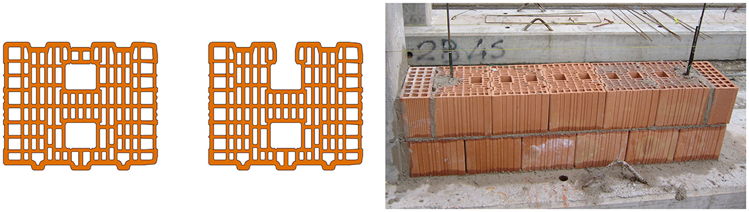
Figure 1. Clay unit of the construction system (left); example of reinforced masonry infill wall construction (right).
In the RM infill walls, four vertical reinforcement bars, with spacing varying between 1,000 and 1,500 mm and with a diameter of 8 mm, were used. In the initial system development, the vertical bars were anchored to both the base and the top beam of the RC frame, whereas in the final configuration reached after the initial tests, anchoring is provided only to the base beam. The horizontal reinforcement (stirrups) was made of two bars with a diameter of 6 mm, placed every three joints and with no connection to the RC frame columns. The stirrups were placed starting from the second mortar bed joint in the full infill walls and starting from the third mortar bed joint in the partial infill walls, for a total of four or three stirrups, respectively (Figure 3).
Experimental Program
The experimental program has been defined in order to investigate the combined IP/OOP behavior of robust clay masonry infill wall construction systems. In particular, the specimens were IP tested, imposing different levels of maximum displacements of the frame top beam. Only after the occurrence of IP damage, differentiated according to the IP drift attained by the frame, were the specimens tested OOP until collapse.
The other objectives of the experimental campaign, as already mentioned in the introduction, were as follows: comparing the effectiveness of unreinforced and reinforced masonry solutions, evaluating the behavior of infill walls that fully fill the frame and of partial infill walls having some openings, and, in the latter case, verifying the effect of lintels.
Material Properties
Mechanical characterization of materials and masonry sub-assemblages preceded tests on frame specimens. Standard tests on units, mortar, and reinforcement bars, compression tests on URM walls, and flexural tests on RM walls were carried out.
The clay units were tested in compression in the directions parallel to the holes and orthogonal to the holes in the plane of the wall, according to EN 772-1 [CEN (European Committee for Standardization), 2011]. The gross average compressive strength was 13.5 and 2.6 N/mm2 in the vertical and the horizontal directions, respectively. The corresponding values of elastic moduli, calculated according to UNI 6556 [UNI (Italian Committee for Standardisation), 1976], were, respectively, 10,925 and 2,857 N/mm2. The gross average tensile strength, measured according to UNI 8942-3 [UNI (Italian Committee for Standardisation), 1986], was 0.32 N/mm2 in the direction parallel to the wall length (failure line orthogonal to the masonry length) and 0.59 N/mm2 in the transversal direction (failure line along the masonry length).
Mortar samples were taken while the specimens were being constructed for laboratory testing and were tested after 28 days of curing, according to EN 1015-11 [CEN (European Committee for Standardization), 2006a] and EN 13412 [CEN (European Committee for Standardization), 2006b]. The average values of flexural strength, compressive strength, and elastic modulus were, respectively, equal to 5.7, 19.9, and 18,367 N/mm2.
The reinforcement bars were made of hot-rolled B450C steel. Both horizontal and vertical bars were tested in uniaxial tension, according to EN ISO 6892-1 [CEN (European Committee for Standardization), 2009] and EN ISO 15630 [CEN (European Committee for Standardization), 2010], respectively, obtaining the average values of 503 and 535 N/mm2 as yield strength, 593 and 625 N/mm2 as tensile strength, and 190 and 198 N/mm2 as elastic modulus.
Lastly, eight compression tests were carried out on URM specimens having a dimension of about 1.0 × 1.0 m, according to EN 1052-1 [CEN (European Committee for Standardization), 2001a, see Figure 2]. Four specimens (URM_V) were tested in the vertical direction, i.e., loading in the direction orthogonal to the bed joints, and other four specimens (URM_H) were tested in the horizontal direction, i.e., loading in the direction parallel to the bed joints. Table 1 shows the average values of stress at first cracking (σ1), maximum compressive strength (σmax), modulus of elasticity (E), Poisson's ratio (ν), and shear modulus (G) in between 10 and 40% of peak strength.
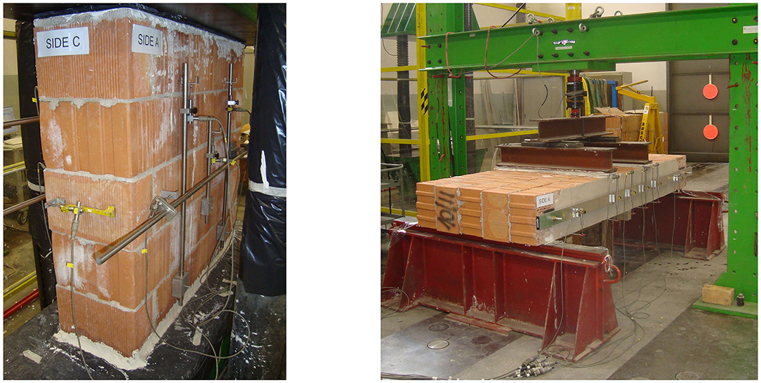
Figure 2. View of compression test (vertical loading, left); view of flexural test (failure line orthogonal to bed joints, right).
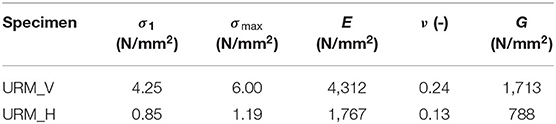
Table 1. Compression test results.
Flexural tests were carried out on six RM specimens having a dimension of about 1.0 × 2.5 m, according to EN 1052-2 [CEN (European Committee for Standardization), 2001b, see Figure 2]. Three specimens (RM_V) were tested in flexure with the failure line parallel to the bed joints (vertical masonry strips), and three other specimens (RM_H) were tested in flexure with the failure line orthogonal to the bed joints (horizontal masonry strips). Table 2 shows the average values of the bending moment at first cracking (M1) and yielding (My), of the maximum moment (Mmax), of the corresponding mid-span deflections (δ1, δy, and δmax), and of the ultimate deflection at 20% strength decrease (δu).
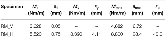
Table 2. Flexural test results.
Combined In-Plane/Out-of-Plane Test Program
The combined IP-OOP tests were conducted on full-scale, one-bay and one-story, RC frames, infilled with the URM and RM infill wall systems described above. The choice to adopt full-scale specimens was made to avoid any scaling effect related to the relative stiffness ratio between the RC frame and the infill wall. The specimens were designed following the criteria described in da Porto et al. (2013), and their main characteristics are briefly reported below.
The infill wall dimensions were 4.15 × 2.65 m (length × height), and the RC frame was designed as part of the ground-level frame of a regular and typical three-story Italian residential building (class of use II), with columns spaced 4.5 m × 4.5 m and stories 3.0 m high. The frame was seismically designed in a high-ductility class [class “A” according to MIT (Italian Ministry of Infrastructure Transport), 2008], considering a peak ground acceleration of 0.25 g, thus ensuring the hierarchy of strength of the RC cross-sections.
The main infilled RC frames tested in this research had the following characteristics:
• two URM fully infilled RC frames, IP tested up to 0.5% (2-ID) and 1.2% drift (3-IU);
• two RM fully infilled RC frames, IP tested up to 0.5% (4-RID) and 1.2% drift (5-RIU);
• one URM partially infilled RC frame, IP tested up to 1.0% drift (6-PIU);
• one RM partially infilled RC frame, IP tested up to 1.0% drift (8-PRIU); and
• one RM partially infilled RC frame, with a lintel above the opening, IP tested up to 1.2% drift (11-PRIU).
To evaluate the reciprocal influence between the masonry infill wall and the RC frame, a bare frame (i.e., without any infill wall, specimen 1-RCF) was built, and tested IP was up to 3.4% drift. Table 3 is a list of the specimens of the above-described test program and Figure 3 shows some of them.
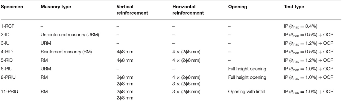
Table 3. In-plane (IP)–out-of-plane (OOP) test program on full-scale specimens.
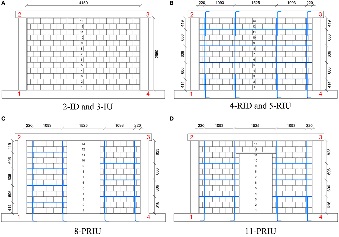
Figure 3. Fully filled frames with unreinforced masonry (A); fully filled frames with reinforced masonry (RM) (B); partially RM filled frame with opening (C); partially RM filled frame with opening and lintel (D).
Besides these eight specimens, whose results will be thoroughly described in the following, three other specimens were tested. Specimen 7-PRIU was similar to specimen 8-PRIU, i.e., partial RM infill with a full height opening, with the difference that the anchorage of the vertical reinforcement is realized both in the bottom RC beam (as for 8-PRIU) and in the top RC beam. Specimen 9-PRIU also had a partial infill with a full height opening, with the particularity that one of the two partial walls only had vertical reinforcement (three bars of 8-mm diameter at about 550-mm spacing), whereas the other only had horizontal reinforcement (four stirrups of 6-mm diameter at about 600-mm spacing). Lastly, specimen 10-P still had a partial infill with a full height opening, but one partial wall was made of URM (similarly to 6-PIU) and the other of RM (similarly to 8-PRIU). These last two walls were simply tested OOP to get information on the OOP capacity of the walls not previously damaged.
The results of these additional specimens will not be presented in detail, but some specific aspects of their behavior will be described, where relevant.
Test Setup, Instrumentation, and Procedure
The experimental setup (Figure 4) consisted of two servo-controlled hydraulic actuators placed over the beam-column nodes for applying vertical loads. The load is transferred to the columns through a self-locking device, hinged to a reaction steel beam at the top of the actuator, and connected by ball-and-socket joints to the RC frame bottom beam. An axial load of 400 kN on each column was kept constant during the IP and OOP tests. One servo-controlled hydraulic actuator is placed at the height of the top beam for applying horizontal IP cyclic displacements. Lastly, the loading system for the OOP test is made of commercial steel profiles connected to another hydraulic jack. The system allows applying four punctual forces of equal intensity at every third of the infill wall length and height, in the case of full infill walls, and two linear forces of equal intensity at every third of the infill wall height, in the case of infill walls with openings. Two linear guides on the lateral face of the top beam constrain the frame displacements in the OOP direction.
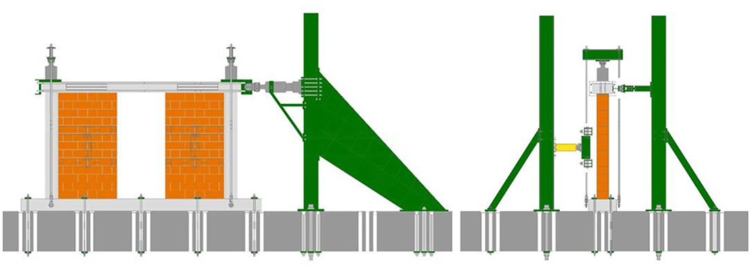
Figure 4. In-plane (left) and out-of-plane (right) test setup.
In the first phase of the test, the frame columns are preloaded to simulate the presence of upper stories. Then, horizontal cyclic displacements are applied to the upper beam with a quasi-static procedure (maximum stroke speed of < 0.5 mm/s). The displacement history consists of cyclic displacements of increasing amplitude that are repeated three times for each amplitude (Figure 5); the target displacements were defined based on the following inter-story drifts:
- ± 0.05, ± 0.1, ± 0.2, ± 0.3, ± 0.4, ± 0.5, ± 0.6, ± 0.8, ± 1.0, and ± 1.2%.
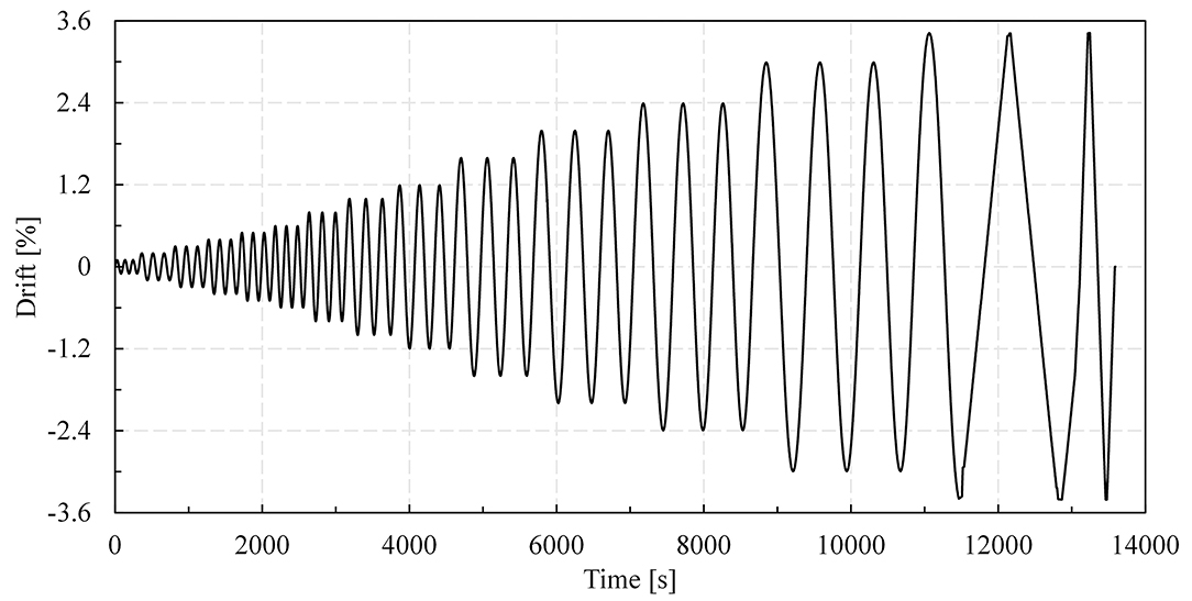
Figure 5. In-plane test protocol adopted for infilled frames (up to 1.2% drift) and bare frame.
At the end of the IP test, the specimens were brought back to null horizontal displacement, and then the OOP test was performed by applying a monotonic incremental force until the collapse of the infill.
The in-plane test on the bare frame continued up to the maximum actuator stroke, to study its elastic and plastic behavior; hence, the following top displacement cycles were added: ± 1.6, ± 2.0, ± 2.4, ± 3.2, and ± 3.4%. The three main target inter-story drifts, at which the IP tests were stopped to start the OOP tests, were identified as 0.5, 1.0, and 1.2% based on the following considerations:
- 0.5% drift corresponds to the damage limit state of fully infilled frames, according to the Italian building code [MIT (Italian Ministry of Infrastructure Transport), 2008, 2018] and EN 1998-1 [CEN (European Committee for Standardization), 2004];
- 1.0% drift has been assumed, on the basis of the experimental observations of damage propagation, as a life safety limit state for the partial infill walls; and
- 1.2% drift has been assumed, on the basis of the experimental observations of damage propagation, as a life safety limit state for the full infill walls.
The instrumentation setup was designed to measure the global and local deformation of the RC frames, the global IP deformation of infill walls and the local strain on masonry due to the infill wall–RC frame interaction, the global OOP deflection shape of infill walls, and the strain of some horizontal and vertical reinforcement bars used in the RM walls. For this purpose, 35 linear potentiometers, 15 draw wire potentiometers, and 12 strain gauges (on the reinforcement bars) were used, as shown in Figure 6.
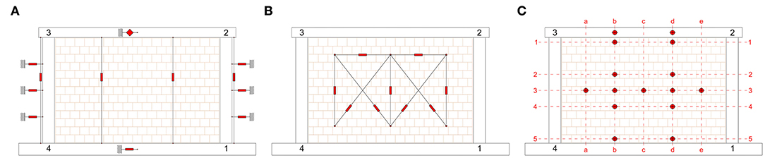
Figure 6. Linear and draw wire potentiometers measuring local and global reinforced masonry frame deformation (A); linear and draw wire potentiometers measuring global masonry in-plane deformation (B); draw wire potentiometers measuring out-of-plane masonry deflection (C).
Experimental Results
Figure 7 shows the crack patterns of the specimens with masonry infill walls at the end of the IP tests. The data acquired during the tests were used to obtain the hysteresis loops shown in Figure 8. The hysteresis loops were not completely symmetrical due to a non-symmetrical damage on the reverse loading cycles and, in two cases (3-IU and 11-PRIU), due to a sudden sliding of the bottom RC beam on the laboratory floor, which was immediately corrected during the test. However, in general, it can be seen that the test phases give comparable results, demonstrating the reliability of the tests.
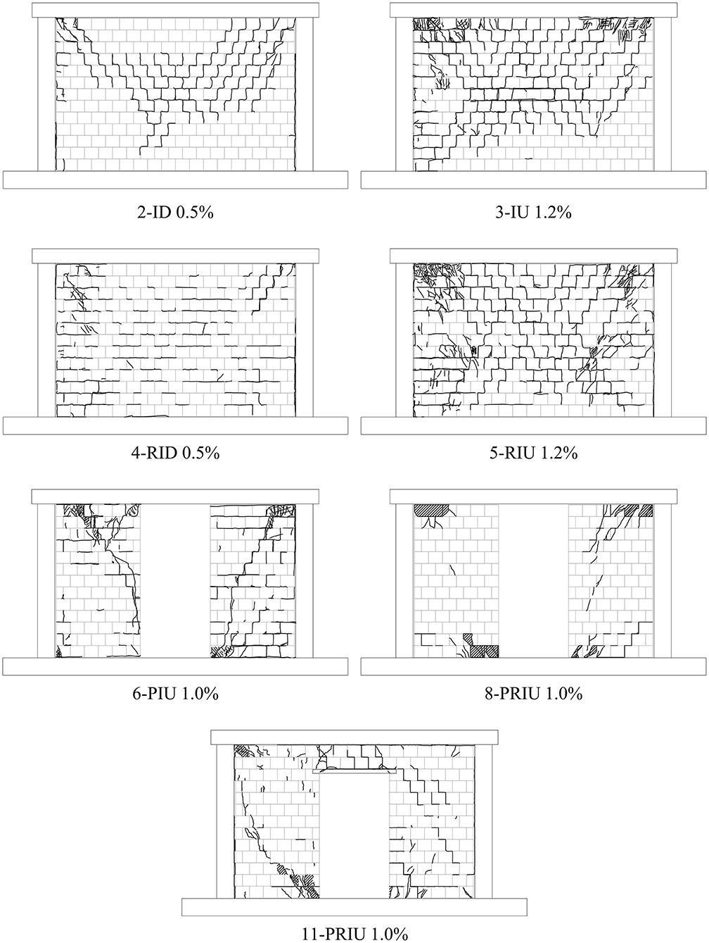
Figure 7. Crack pattern at the end of the in-plane tests.
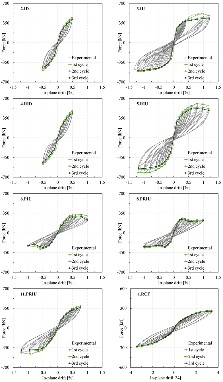
Figure 8. Hysteresis loops and envelope curves of in-plane tests.
The infill force–displacement envelope curves associated with the third IP loading cycle are shown in Figure 9A, and the associated stiffness degradation curves are shown in Figure 9B. In Figure 9A, the envelope curve obtained from the test of the bare frame (1-RCF) (Figure 10A) was subtracted from the envelope curves obtained by testing the infilled frames (Figure 10B), allowing to derive the IP behavior of the infill wall as the difference between the force–displacement envelope curve of the infilled frame and that of the bare frame [according to the procedure described in Minotto et al. (2020)]. The masonry infill wall contribution and limit states are thus derived with reference to these “subtracted” curves. Conversely, energy dissipation capacity and equivalent viscous damping ratio (Figure 11) are directly given with reference to the global specimen behavior, as in this case the direct comparison with the 1-RCF specimen highlights the differences of the infilled and bare frame specimen responses.
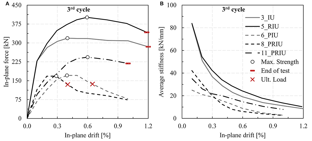
Figure 9. In-plane tests (infill contribution): load-drift envelope curves (A); stiffness degradation (B).
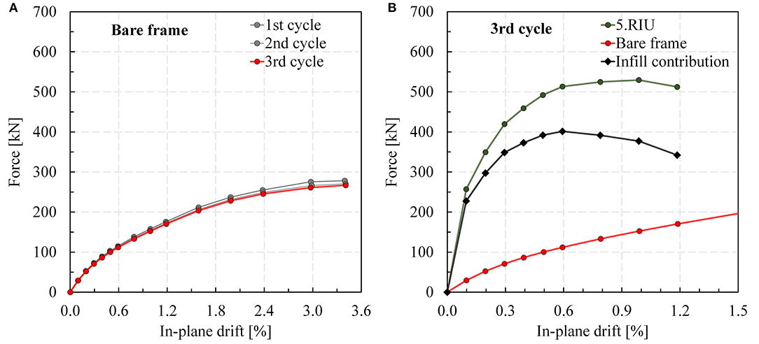
Figure 10. In-plane load-drift envelope curves of bare frame (A); infill wall contribution by subtraction (B).
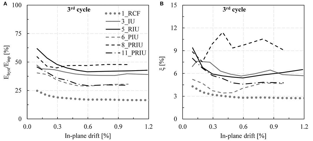
Figure 11. In-plane tests (specimens θ = 1.0–1.2%): energy dissipation capacity (Ehyst/Einp) per loading cycle (A) and equivalent viscous damping ratio (ξ) per loading cycle (B).
Lastly, Table 4 is a list, with reference to the infill contribution only, of the initial stiffness values Kinit (in-between 0 and 0.1% drift) and the load and drift values measured at characteristic limit states, corresponding to maximum strength (Fmax, θmax) and ultimate displacement possibly attained during the IP test (Fu, θu).
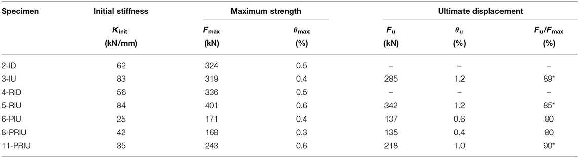
Table 4. In-plane test results (infill contribution; *ultimate condition, i.e., 20% Fmax degradation, not reached).
The data processing and presentation of OOP tests is relatively simpler. Figure 12 shows some details of the failure mechanisms, whereas Figure 13 shows the OOP force–displacement curves of all specimens. Table 5 is a list of load and deflection values measured at maximum strength (Fmax, dmax) and at ultimate deflection, conventionally set at 20% degradation of the OOP strength (Fdu, du). The presented values of deflection are those corresponding to the midspan control point, i.e., the maximum values for each tested specimen.
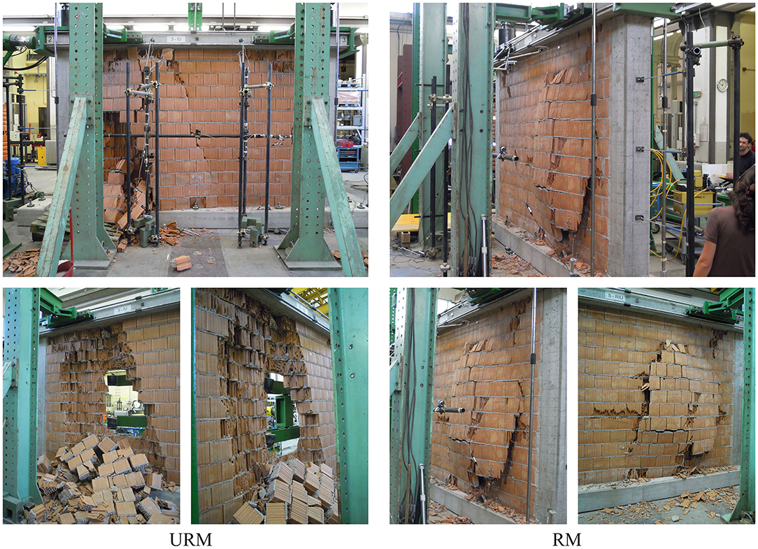
Figure 12. Expulsion of masonry portions at ultimate deflection in unreinforced masonry specimens (left); out-of-plane damage at ultimate deflection in reinforced masonry specimens (right).
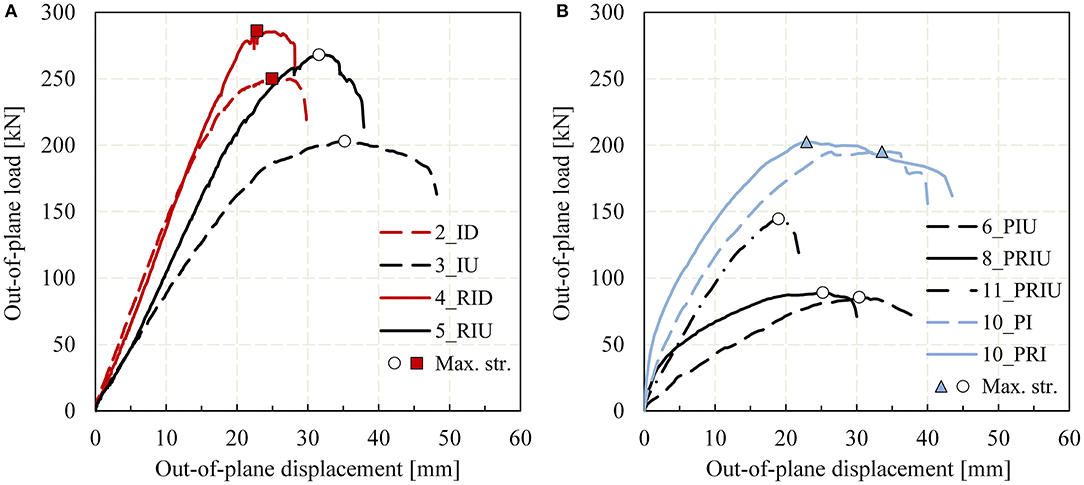
Figure 13. Out-of-plane force–displacement curves for fully filled specimens (A) and for partial infill walls (B).
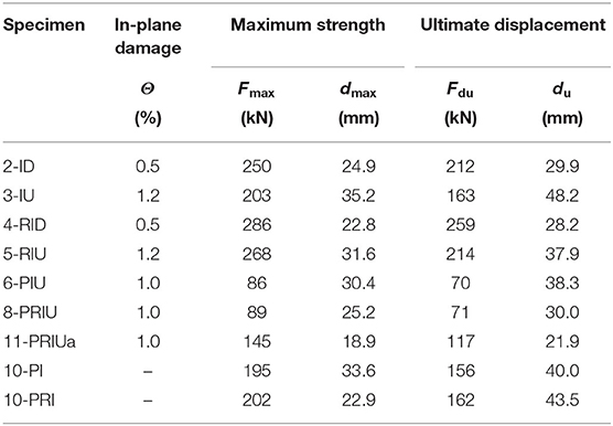
Table 5. Out-of-plane test results.
In-Plane Cyclic Tests
During the IP tests, all infilled specimens presented the first non-linearity starting from 0.1% drift, as can be seen also by the change of stiffness in the envelope curves (Figure 9B). First cracks develop at the infill masonry wall/RC frame interface. The full masonry infill walls start cracking in between 0.2 and 0.4% drift levels. Then, stepped cracks along the head and bed joints develop from the masonry corner to the wall center (Figure 7). In between 0.4 and 0.6% drift, these infill wall systems reach their maximum strength (Fmax). At this point also, the RC frame nodes start cracking (minor cracks started already at 0.2% drift). The RM infill wall system reaches an average IP maximum strength (5-RIU, 401 kN at 0.6% drift) that is 26% higher than that of the URM system (3-IU, 319 kN at 0.4% drift). In RM walls, diagonal cracks cross both the masonry joints and the units, but they have a smaller dimension and a slightly higher diffusion on the masonry surface (Figure 7).
Regarding the partial masonry infill walls (infills with openings), all three tested specimens have smaller and more variable initial stiffness than the fully filled specimens, with the highest values shown by 8-PRIU, at least up to 0.3% drift. At this point, this RM specimen (8-PRIU) reaches a maximum strength of 168 kN, whereas the URM specimen (6-PIU) reaches, at 0.4% drift, a maximum strength of 171 kN (Figure 9A). The RM specimen with the lintel (11-PRIU) reaches its maximum strength at 0.6% drift with load values that, related to the effective load-bearing area of the wall, are comparable to those of fully filled infill masonry walls (243 kN). Regarding the crack pattern, the URM specimen (6-PIU) is characterized by the sudden formation of sharp diagonal cracks along the compressed struts, starting from the RC frame nodes to the RC base beam (Figure 7). The crack pattern of the RM specimen (8-PRIU) develops more gradually, involving mainly the compressed toes close to the RC frame nodes and base beam, and leaves almost intact the central part of the walls (Figure 7). The RM specimen with lintel presents a more moderate and uniform damage pattern. At the ultimate drift, there are light diagonal cracks developing in both loading directions, but definitely smaller than those of 6-PIU, and a limited toe crushing close to the masonry corner (Figure 7).
The energy dissipation capacity of all tested specimens is greater than that of the bare RC frame, with values that, starting from 0.5% drift, are in between 40 and 50%, compared to 20% of the bare frame (Figure 11A). The equivalent viscous damping ratio as well is higher in infilled specimens than in bare RC frame, with values (starting from 0.5% drift) in between 6 and 8%, compared to 4% of the bare frame. 8-PRIU only deviates from these values, reaching higher values (Figure 11B). This might be due to the higher rotations of the two masonry panels observed during the test, with subsequent development of friction along the RC frame beam and progressive crushing of the corner units.
Results of Out-of-Plane Tests
After the cyclic in-plane test, the masonry infill walls were subjected to monotonic out-of-plane loads until collapse. All tested walls developed an arching mechanism, mainly in the vertical direction. The stiffness degradation (Figure 13) during the OOP test is mainly due to the progressive crushing of the units caused by the compressed struts developed in the arching mechanism. In the case of the full infill walls, the particular load application procedure (four-point loads) caused some local failures in the final test phases, after the attainment of the maximum OOP strength. Tests on RM specimens showed that the insertion of vertical and horizontal reinforcement bars allowed containing the OOP expulsion of masonry portions in reinforced specimens, at least until the attainment of the ultimate deflection (at 80% of maximum strength) and after (Figure 12).
The OOP strength of full RM masonry infill walls was higher than that of URM infills, particularly for higher levels of previous IP drift (Fmax of 5-RIU is 32% higher than that of 3-IU; Fmax of 4-RID is 14% higher than that of 2-ID). The strength decrease due to previous IP damage was smaller in RM walls (−6% going from 0.5 to 1.2% drift) than in URM walls (−20% going from 0.5 to 1.2% drift). Similar observations can be drawn for OOP stiffness (see Figure 13).
Partial RM infill masonry wall (8-PRIU) presented similar values of OOP strength compared to URM wall (6-PIU), although with different values of initial stiffness and ultimate deflections (see Figure 13). The URM wall (6-PIU), despite the very significant cracking during IP tests, presented a surprisingly high value of OOP strength, due to the indentation of the masonry portions separated by the crack and the subsequent activation of the arching mechanisms in this case, too. However, this most likely happened because of the specific (quasi-static) loading condition; during a real dynamic excitation, it is reasonable that the two damaged and unstable portions of masonry would collapse without developing any resisting mechanism.
Partial RM infill masonry wall with lintel (11-PRIU) presented a completely different OOP behavior, reaching values of initial stiffness and maximum strength definitely higher than those of the RM specimen without lintel (8-PRIU) (see Figure 13). The presence of the lintel, due to its coupling effect, reduces the relative rotation of the two masonry panels during the IP cyclic displacements, and this, in turn, reduces the unit damage at the toe (close to the masonry corner, at the top and bottom beams), thus also increasing the OOP capacity.
In addition to these tests, a further test (10-P) was carried out on a specimen without carrying out a previous IP test. The objective was to experimentally evaluate the maximum OOP capacity due to the activation of the arching mechanism within the masonry thickness. The OOP force–displacement curves associated with the URM and RM walls of this specimen (respectively, 10-PI and 10-PRI in Figure 13B) show values of initial stiffness, maximum strength, and ultimate deflection, which are clearly higher than those of the partial specimens previously tested IP, with and without lintel.
Effect of Reinforcement
Although the behavior of full URM masonry infill walls is already adequate due to the unit robustness and the overall masonry thickness, the positive effect of the reinforcement in the full RM masonry infill walls is evident. In particular, the IP behavior is characterized by a drift level at the attainment of the peak strength (conventionally taken as damage limit state for the masonry infill) that changes from 0.4 to 0.6% in URM and RM specimens. The RM strength is 26% higher than that of the URM specimen. The damage in RM walls is more diffused but locally less intense than in URM walls. This, in turn, improves the OOP behavior of the RM walls, for which the OOP strength is higher than that of URM infills, and particularly for higher levels of previous IP drift, as the strength degradation due to previous IP damage is smaller in RM than URM walls.
In the case of partial infills (walls with openings), omitting the case of the wall with lintel, the situation is more complex. Indeed looking at the load–displacement envelop curves, the RM specimen appears more fragile, with peak strength (hence damage limit state) reached at 0.3% drift (compared to 0.4% of the URM specimen), similar maximum strength (168 kN), and smaller ultimate displacement (0.4% drift compared to 0.65% of the URM specimen). However, this might be due also to the higher initial stiffness of the RM wall, and indeed besides the different initial stiffness, the overall shape of the IP load–drift curve in the two cases is quite similar. In the case of partial infills, in any case, the beneficial effect of the reinforcement can be seen in a definitely less critical crack pattern and less fragile crack propagation, a very high energy dissipation capacity, and better control of the OOP expulsion of the masonry walls.
Lastly, in both cases, full and partial infill walls, the presence of the reinforcement bars makes the final crack pattern less severe, still positively increasing the energy dissipation capacity and equivalent viscous damping ratio of the specimens.
As mentioned above, two other specimens (7-PRIU and 8-PRIU) with partial infill walls and a full height opening, whose results were not discussed before, were tested during the experimental campaign. The first case, 7-PRIU, had the two walls made as in 8-PRIU, except for the fact that the vertical reinforcement was anchored on both the bottom and the top RC beams. Probably due to the rigid connection to the top beam and therefore to a more intense stress transfer at the top beam–panel interface, a much more pronounced crushing of the entire upper course of the masonry panels was observed compared to that in 8-PRIU, starting from a relatively low drift level. This even caused, at 0.8% drift, the failure of one of the vertical reinforcement bars close to the RC frame node (Figure 14A). This type of damage at the top course prevents the infill wall from fully exploiting its IP capacity and, above all, does not allow developing a proper resisting mechanism when the infill wall is loaded OOP. Hence, the OOP failure occurs with an almost rigid outwards rotation of the infill panels (Figure 14B). Based on this evidence, in the prosecution of the research, top beam–infill wall connections were avoided. This was also justified by the fact that, to prevent the OOP collapse of this type of walls, it is very important to preserve the top masonry course integrity, allowing an arching mechanism to develop within the (considerable) masonry thickness.
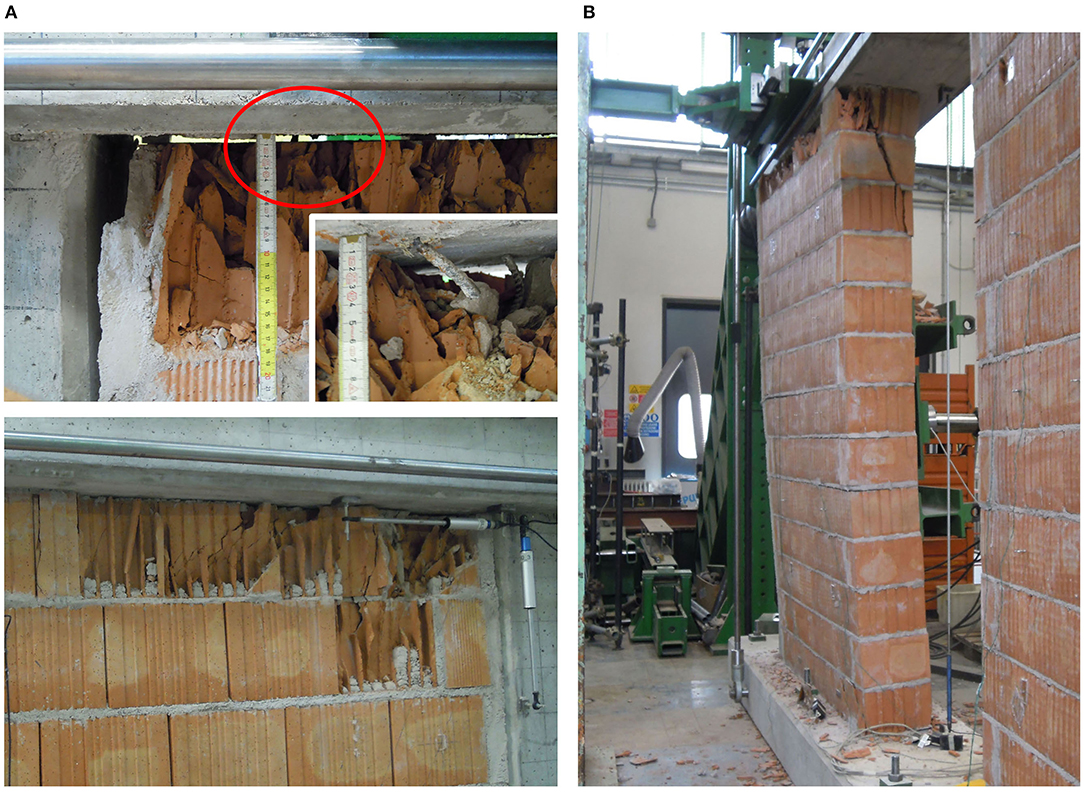
Figure 14. 7-PRIU: effect of crushing at the top course, with a view on a vertical reinforcement bar (A); effect of global overturning due to the weak top course (B).
The second case, 9-PRIU, had two different panels, one made with vertical reinforcement only (three bars of 8-mm diameter at about 550-mm spacing) and the other with horizontal reinforcement only (four stirrups of 6-mm diameter at about 600-mm spacing). The main aim for testing this specimen was understanding whether a partial reinforcement configuration, based on vertical or horizontal reinforcement only, was also effective.
This test was characterized by the premature failure of the panel with vertical reinforcement only that, at 0.4% drift, formed a sharp diagonal crack along the compressed strut, starting from the RC frame node to the RC base beam. This very fragile crack subdivided the masonry panel into two unstable triangular portions (Figures 15A,B), similarly to what happened in 6-PIU. The very asymmetrical behavior that the specimen presented starting from this moment onwards does not allow one to make a clear assessment of the behavior of the second masonry panel, with horizontal reinforcement only. In any case, partly because of the modified frame behavior, the second panel reduced the IP rotation effect observed in the previous 6-PIU and 8-PRIU specimens, and this reduced the damage level close to the masonry corners (close to the RC frame node and to the base beam), limiting the overall crack pattern (Figure 15C) and improving the general behavior of the panel with horizontal reinforcement only.
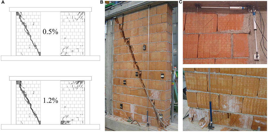
Figure 15. 9-PRIU: damage pattern at 0.5 and 1.0% drift (A); damage on the vertically reinforced wall (B); slight damage and toe crushing of the horizontally reinforced wall (C).
Effect of Openings
As reported in “Section In-plane cyclic tests” and “Section Results of out-of-plane tests,” when there is an opening in the wall, the behavior of the infill is worse than in the case of the full infill walls. In this case, in general, the behavior under IP loading is more fragile, with a trend to have less diffused, but sharper, diagonal cracks and sometimes intense toe crushing. This crack pattern is more intense and fragile in the case of URM walls (6-PIU). The stiffness of partial walls is obviously smaller than that of full infills, but the strength values of the partial walls, related to the effective load-bearing area of the panel, are less than proportional compared to those of fully filled infill walls. These drawbacks are only partly mitigated by the presence of reinforcement in the RM specimen (8-PRIU).
The OOP behavior of partial infill walls is strongly affected by the specific IP behavior. Indeed the significant damage state at 1.0% drift implies a stronger strength degradation for the masonry properties, thus the OOP capacity of 6-PIU and 8-PRIU is less than half that of a partial wall without any previous IP damage (10-P), and this strong reduction is probably higher than the corresponding reduction that could be inferred in full infill walls, from the comparison of data that we have at 0.5 and 1.2% drift. Besides that, partial masonry infill walls are less constrained than full infills; hence, it is more difficult that a plate or a horizontal arching mechanism gives a contribution to the overall OOP strength.
The coupling effect given by the presence of masonry lintels completely change the behavior of masonry infill walls with openings; this effect induces a change of crack pattern, avoiding the very fragile and strong damage undergone by the URM wall with opening but also allows less damage than the RM wall with opening. The high values of IP capacity reached by the specimen 11-PRIU, due to the simultaneous activation of both masonry panels separated by the opening (as demonstrated by the diagonal cracks oriented in both directions in each masonry panel), make it more similar to full infill walls. Following the enhancement of the IP behavior, the OOP capacity of the partial infill wall with lintel is also definitely improved.
Analytical Modeling of the OOP Capacity of Infill Walls
State of the Art and Development of a New Analytical Model
The OOP capacity of infill walls is generally expressed in terms of the maximum uniform lateral pressure qlat which causes their collapse. The first analytical solutions for the prediction of qlat were based on the flexural response of the infill panel, modeled with homogeneous isotropic material with linear elastic behavior, relying on its tensile strength (Timoshenko and Woinowsh-Krieger, 1959) or flexural strength (Haseltine et al., 1977). However, subsequent experimental studies highlighted the limits of these solutions, demonstrating that the OOP response of infill panels, in particular after their cracking, is governed by the arching mechanism, which can be modeled considering the infill panel divided into two rigid blocks that rotate about their supported ends, as shown in Figure 16A. According to this approach, the OOP capacity of the panel depends on the compressive strength of the masonry, except for possible phenomena of “snap-through” instability in the case of high OOP displacements (e.g., for infill walls with significant slenderness). The first study in this regard is that of McDowell et al. (1956) under the hypothesis of one-way behavior of a masonry strip having rigid supports at the ends. Subsequently, other researchers included in their evaluations the two-way action of the panel and the deformability of the supports (Dawe and Seah, 1989b) and also investigated the effects of degradation due to previous IP damage (Angel et al., 1994; Abrams et al., 1996). An in-depth literature review on these analytical solutions, developed for the prediction of the OOP response of infilled frames, is presented in Asteris et al. (2017), together with a discussion on the effectiveness of recent integrated IP/OOP numerical models to be used in structural analysis (which is outside the scope of this study). Furthermore, an extension of the arching mechanism solution was proposed by Hak et al. (2013) to take into account the contribution of a possible external reinforcement of the panel. Among the first experimental and analytical studies on the OOP infill capacity, that of Angel et al. (1994) is one of the most comprehensive, and its results converged, with some simplification, in the following expression proposed in FEMA-306 [FEMA (Federal Emergency Management Agency), 1998]:
where λ is a slenderness parameter dependent on the hw/tw ratio and defined in Tables 8–5 of the FEMA-306, and R1 and R2 are OOP strength reduction factors that take into account, respectively, the existing IP damage and the confining frame flexibility [for further details, please refer to FEMA (Federal Emergency Management Agency), 1998].
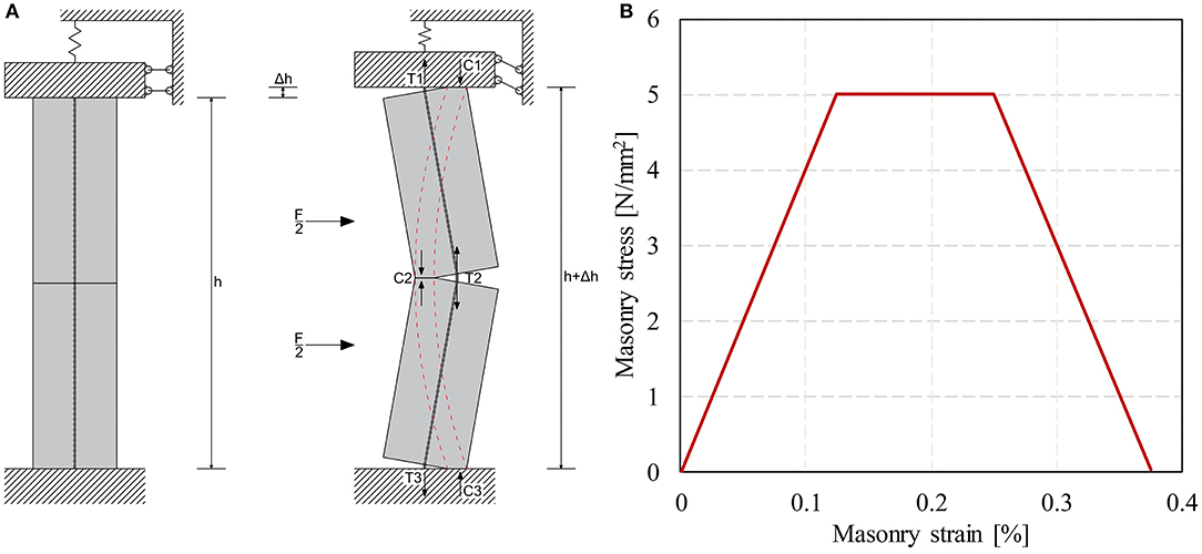
Figure 16. Static scheme of infill wall model (A); stress-strain law of masonry in compression (B).
For the verification of the OOP capacity of infill walls, EN 1996-1-1 [CEN (European Committee for Standardization), 2005] also provides a simplified formula based on the arching mechanism, although without indications about the IP/OOP interaction, whereas the current EN 1998-1 [CEN (European Committee for Standardization), 2004] is silent in this regard, and the Italian building code [MIT (Italian Ministry of Infrastructure Transport), 2018] generically refers to flexural mechanism for the verification of load-bearing masonry walls. However, the bending mechanism is inadequate to evaluate the OOP capacity of infill walls, as they are generally characterized by the absence of vertical load (besides their self-weight) and by a negligible tensile strength (especially if previously damaged); therefore, this mechanism fails to explain the significant OOP infill strengths observed in the experimental tests (as above-mentioned). In addition, the compression level in the infill wall, necessary to apply a flexural model, varies significantly with the OOP deflection of the panel. On the other hand, verification formulas based on the flexural mechanism could be adequate in the case of thin, externally reinforced/strengthened infill walls; indeed Minotto et al. (2020) recently proposed a new OOP capacity model for this type of panels based on the flexural model proposed in CNR-DT 200 [CNR (National Research Council), 2004] but which includes the contribution of the vertical load developed during the OOP response of the panel, although in a simplified way.
Therefore, given the shortcomings of the standards in this regard and the lack of widely accepted solutions, a new analytical model, based on the arching mechanism, was developed in this study in order to further investigate the OOP behavior of clay masonry infill walls, both unreinforced and reinforced. This model, which includes the non-linear behavior of masonry, the possible presence of reinforcements, and the deformability of the supports, can effectively reproduce the entire OOP capacity curve of the infill wall, predicting its experimental OOP response not only in terms of strength but also of stiffness. This represents a novelty, as the few similar analytical models available in the literature, such as those of Tumialan et al. (2003b) and Varela-Rivera et al. (2012), are based on linear modeling of the infill panel and allow predicting the ultimate OOP capacity only.
In our proposal, the infill wall is idealized as a vertical strip of unitary depth placed within linear elastic supports in vertical direction and subjected to OOP loads applied to the thirds of the infill height, consistently with the test setup (Figure 16A). To avoid overestimation of the infill capacity due to the generally adopted simplifying assumptions (such as the infinite stiffness of the RC confining elements), the proposed model takes into account the beam vertical deformation, the ratio between infill wall length and frame span, and the position of the infill wall within the frame. In particular, the average vertical stiffness Kv, avg of the upper beam used in the model was calculated as the ratio between the integral of its bending stiffness, Kv(x), over the total length of the beam, and the beam length l, as shown in Equation (2). For the calculation of Kv(x), the rotational elastic stiffness of the end supports of the beam was calibrated in order to obtain the best fit with the experimental results.
The compressive behavior of masonry was modeled by an elasto-plastic stress–strain law, which also includes a softening branch (Figure 16B), whereas the tensile strength of masonry was assumed to be zero. The rigid rotation of the two wall segments implies reaction forces and section deformations, which modify the initial geometrical configuration of the system. The OOP strength of the infill walls can therefore be calculated using an iterative procedure, imposing the balance of the masonry sections that are subjected to both the reaction forces of the frame and the OOP loads. According to this approach, the collapse of the infill wall can be due to either masonry crushing or loss of balance, allowing a reliable evaluation of the actual behavior.
Model Calibration
The experimental OOP tests were performed on masonry walls previously subjected to different levels of IP drift, hence damage. To take into account the degradation of mechanical properties of masonry due to IP damage, two independent reduction factors for the compressive strength (fm) and the elastic modulus (Em), respectively, α and β, were introduced in Equations (3) and (4). Both coefficients depend on the type of masonry (URM and RM) and on the attained drift level, according to Equations (5) and (6).
Table 6 gives the coefficients a, b, c, and d in Equations (5) and (6), obtained through regression analysis based on experimental data. Figure 17 shows the comparison between the load–deflection curves obtained with the analytical model (in red) and the experimental curves (in gray). Black squares and black dots highlight the achievement of the masonry elastic limit (at cross-section level) and the peak strength, respectively. In the case of RM, black triangles highlight the yielding of vertical bars. As can be seen, the calibrated analytical model allows one to reproduce almost perfectly the OOP load–deflection curves of the tested masonry infill walls.
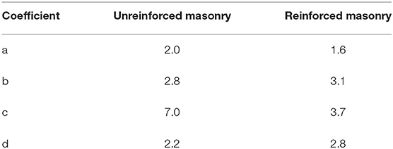
Table 6. Terms of Equations (5) and (6).
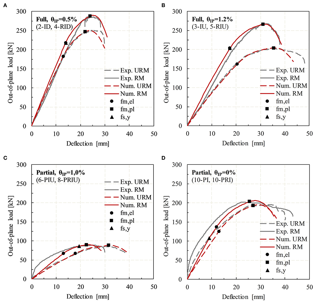
Figure 17. Comparison between experimental and numerical results: unreinforced masonry (URM) and reinforced masonry (RM) full specimens damaged at 0.5% in-plane (IP) drift (A) and 1.2% IP drift (B); URM and RM partial specimens damaged at 1.0% IP drift (C) and without previous IP damage (D).
Figure 18A shows the trend of the reduction factors α and β, which apply to the model input parameters (fm and Em) as a function of the infill IP drift. These analytical laws provide the degradation of the mechanical characteristics of the masonry due to IP damage. However, for design and verification purposes, the evaluation of the performance reduction of the infill wall by applying an overall reduction coefficient R directly to its OOP strength is more effective. In this regard, Figure 18B shows the OOP strength reductions for both URM and RM masonry infill walls tested in this experimental campaign as well as the associated analytical degradation laws obtained by calibration and based on Equation (7) and the coefficients of Table 7.
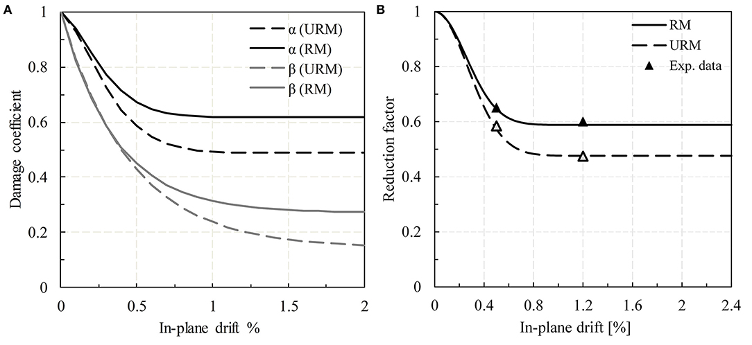
Figure 18. Damage coefficients α and β (A) and out-of-plane strength reduction factors (B) as a function of in-plane drift.
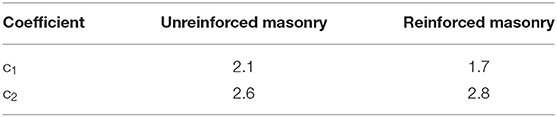
Table 7. Terms of Equation (7).
Quite recently, some researchers have proposed similar degradation laws, calibrated on not only mainly experimental (Morandi et al., 2013; Ricci et al., 2018; Minotto et al., 2020) but also numerical (Cavaleri et al., 2020) results. For comparison purposes, Figure 19 shows the various OOP strength reduction laws provided by previous authors for URM infill walls, including the one proposed in FEMA-306 [FEMA (Federal Emergency Management Agency), 1998, i.e., the R1 factor in Equation (1)]. In particular, since the slenderness of the infill wall (h/t) significantly influences its OOP behavior, these laws are presented grouped in two graphs: Figure 19A refers to slender panels (h/t ≈ 20), whereas Figure 19B refers to squat panels (h/t ≈ 9). It is worth noting that the degradation laws given by Ricci et al. (2018) and FEMA-306 are also a function of wall slenderness; therefore, they are shown in both graphs of Figure 19 with different h/t values; in addition, the law of Cavaleri et al. (2020) is calibrated on the average of numerical results referred to various slenderness values, so it was equally reported in both graphs. Clearly, due to the different type of infills, the two graphs in Figure 19 cover a different range of IP drift values (up to a representative value for the ultimate limit state of the panel). As can be seen from these comparisons: the FEMA formulation does not seem conservative enough; the robust infill walls analyzed in this study show a much lower degradation than the slender ones; in general, the various laws proposed to date for the evaluation of the infill OOP strength reduction, although quite similar in trends, show evident differences which require further investigations and experimental validations.
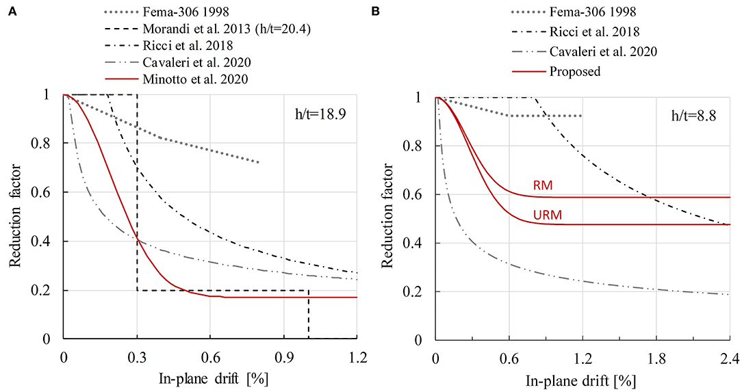
Figure 19. Comparison of the out-of-plane strength degradation laws of slender (A) and squat (B) infill walls.
Parametric Analyses and Results
Some parametric analyses, to investigate the most influential parameters on the OOP capacity of masonry infill walls, were carried out on the basis of the developed model.
First, the top beam stiffness has a significant influence on the OOP strength of the infill wall. Figure 20A shows the variation of the infill OOP maximum strength when changing the ratio between the considered stiffness (Rf) and the experimental one (Rf, exp) for a wall that has undergone a 1.2% IP drift. For low stiffness values, the OOP strength rapidly goes to zero, whereas for higher stiffness values, the OOP strength asymptotically tends to higher values. This is consistent with the smaller rotation of the masonry portion in the case of stiff constraints, which increases the lever arm of internal forces and hence the stabilizing moment, allowing better exploitation of the available masonry compressive strength.
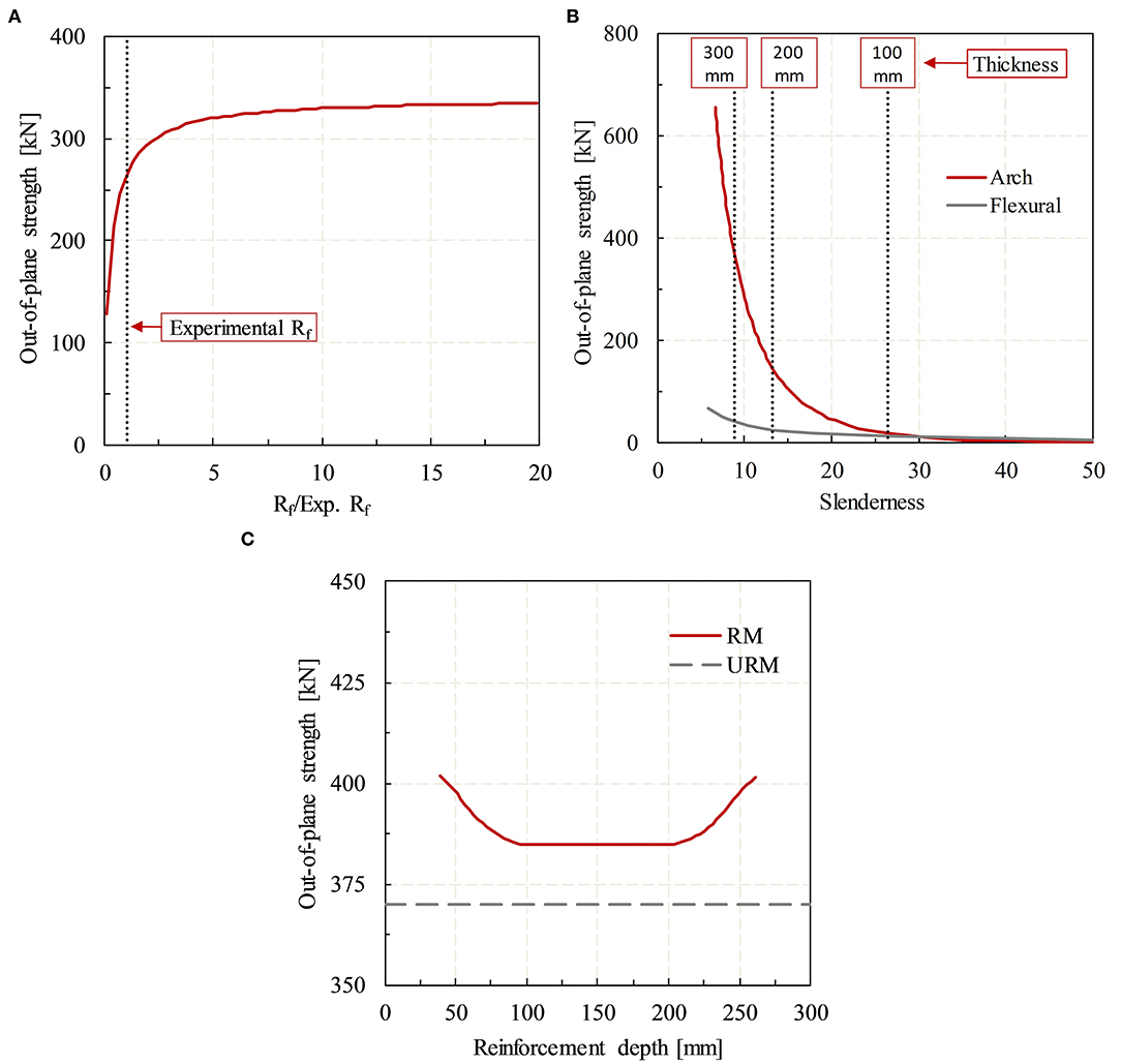
Figure 20. Infill out-of-plane maximum strength as a function of reinforced concrete beam stiffness (A), infill slenderness (B), and vertical reinforcement bar depth (C).
Another very significant parameter is, of course, the thickness of the masonry infill wall. Figure 20B shows the maximum OOP strength varying the masonry slenderness (i.e., height-to-thickness ratio, blue curve). The red curve represents the flexural strength of masonry evaluated according to MIT (Italian Ministry of Infrastructure Transport) (2018). The dotted lines highlight, for a height of the wall corresponding to that of the experimental specimens, the behavior of walls having thickness of 100, 200, and 300 mm. It can be seen that, for high slenderness, the OOP strength tends to very small values, which correspond to the flexural capacity of the wall. Clearly, for very high slenderness, the collapse might be due to local phenomena related to fragile failure of the units or shear failure; hence, the model reliability decreases as far as we try to extrapolate results related to values of slenderness very distant from the experimental ones.
Lastly, the depth of the vertical reinforcing bars within the masonry thickness was evaluated. Figure 20C shows the maximum OOP strength varying the position of the vertical bar. In this case, all the other aspects of the model coincide with the geometrical configuration of the experimental specimens, and the masonry is assumed undamaged. It must be underlined that the main aim to use a RM system for the infill walls is not increasing the masonry strength but, rather, limiting damage and avoiding OOP masonry expulsion in the case of a seismic event. Consistently with these objectives, low reinforcement percentage has been used in the experimental specimens, and vertical bars have been placed at the masonry center line. This position is the least effective under the mechanical point of view, but it is also the least expensive, as it does not require the insertion of reinforcement on both masonry sides. Figure 20C obviously confirms that the center line position is the least effective for the vertical bars; however, it also shows that, due to the very low percentage of reinforcement in the specific case, the increase in strength achievable by placing the bars outwards in the wall is very limited (about 5%).
Conclusions
From the experimental tests and numerical analyses carried out on robust clay masonry infill walls in this research, it can be drawn that:
- Considering the results in terms of general IP behavior (crack pattern, stiffness, and strength) and resulting OOP behavior and capacity after reaching various levels of previous IP damage, the overall performance of robust clay masonry infill wall systems is adequate.
- The presence of a system of vertical and horizontal reinforcement, in full masonry infill walls, slightly reduces the IP damage and increases the IP strength. This, in turn, allows obtaining higher values of OOP capacity for RM walls and smaller impact of previous IP damage on the OOP behavior (smaller degradation of the mechanical properties). In addition, the reinforcement system, both in full and partial infill walls, increases the energy dissipation capacity and the viscous damping ratio of the infills and is very effective to avoid the OOP expulsion of masonry portions, which, on the contrary, is not hindered in the case of URM infills.
- The effect of some reinforcement details, such as anchoring the vertical reinforcement to the top beam, dramatically worsen the behavior of the infill masonry system. At least in this case, where the thickness of the wall itself is already enough to provide good restraint against the OOP overturning, this type of connection is not recommended. In this research, no connection of horizontal bars to the RC frame columns was provided. The tests carried out also evidenced a bad performance of walls reinforced with vertical bars only.
- Partial masonry infill walls (infill with opening) presented a worse behavior than full infill walls. Some specific aspects resulted critical when compared to the corresponding full infills—in particular, the very fragile crack pattern of URM infills and, in general, the anticipation of the limit states. The beneficial effect of reinforcement was also reduced, although it was still evident in some respects, such as controlling the OOP collapse or improving the parameters of the cyclic behavior.
- The coupling effect given by masonry lintels to infills significantly improved the behavior in case of walls with openings, both in the IP and OOP loading conditions, at least in this case of robust masonry systems.
- Considering the results in terms of energy dissipation and equivalent viscous damping, the contribution of robust masonry infill walls to the dissipative behavior of an RC frame is very significant. Therefore, even if the ductility of the RC frame may not be fully exploited, due to the increase in stiffness caused by the presence of robust masonry infill walls, the greater dissipation capacity offered by the masonry system can be advantageous.
- An analytical model was developed based on the arching mechanism, taking into account, although in a simplified way, the RC frame deformability and the degradation of the mechanical properties of the masonry due to IP drift. This model allows estimating the actual OOP load–deflection curves very well.
- From the experimental and model results, it was possible to derive simplified degradation laws of the infill OOP strength due to IP drift to be used for design purposes. These degradation laws were compared with other proposals in the literature, highlighting the high variability between them and, consequently, the need for further investigations.
- In addition, from the parametric analyses carried out, it was possible to estimate, with reference to the infill OOP strength, the influence of the frame stiffness, the values of masonry thickness for which the arching mechanism becomes less effective in favor of a flexural resisting mechanism (slenderness >30), and the small effect of the position of the vertical reinforcement bar in this specific masonry system.
Data Availability Statement
The raw data supporting the conclusions of this article will be made available by the authors, upon reasonable request.
Author Contributions
FdP: conceptualization, methodology, writing-original draft, and supervision. MD: methodology, validation, data curation, writing-review, and editing. NV: investigation, formal analysis, data curation, and software. GG: methodology, investigation, formal analysis, and data curation. All authors contributed to the article and approved the submitted version.
Funding
The authors declare that this study received funding from Cisedil s.r.l. The funder was not involved in the study design, collection, analysis, interpretation of data, the writing of this article or the decision to submit it for publication.
Conflict of Interest
The authors declare that the research was conducted in the absence of any commercial or financial relationships that could be construed as a potential conflict of interest.
Acknowledgments
This research project was supported by Cisedil s.r.l. This work was also carried out in the framework of an activity program funded by the Presidency of the Council of Ministers Department of Civil Protection. Experimental tests were carried out at the Laboratory of Structural Materials Testing, University of Padova, Italy.
References
Abrams, D. P., Angel, R., and Uzarski, J. (1996). Out-of-plane strength of unreinforced masonry infill panels. Earthq. Spectra 12, 825–844.
Angel, R. E., Abrams, D. P., Shapiro, D., Uzarski, J., and Webster, M. (1994). Behavior of Reinforced Concrete Frames With Masonry Infills. Urbana and Champaign, IL: Technical Report, University of Illinois Engineering Experiment Station. College of Engineering. University of Illinois at Urbana-Champaign.
Anil, Ö., and Altin, S. (2007). An experimental study on reinforced concrete partially infilled frames. Eng. Struct. 29, 449–460. doi: 10.1016/j.engstruct.2006.05.011
Asteris, P., Cavaleri, L., Di Trapani, F., and Tsaris, A. (2017). Numerical modelling of out-of-plane response of infilled frames: state of the art and future challenges for the equivalent strut macromodels. Eng. Struct. 132, 110–122. doi: 10.1016/j.engstruct.2016.10.012
Bazzurro, P., Alexander, D., Clemente, P., Comerio, M., De Sortis, A., Filippou, F. C., et al. (2009). “Learning from earthquakes: the Mw 6.3 Abruzzo, Italy, earthquake of April 6, 2009,” in EERI Special Earthquake Report, Earthquake Engineering Research Institute (Oakland, CA), 43–12.
Bergami, A. V., and Nuti, C. (2015). Experimental tests and global modeling of masonry infilled frames. Earthq. Struct. 9, 281–303. doi: 10.12989/eas.2015.9.2.000
Blackard, B., Willam, K., and Sivaselvan, M. (2009). “Experimental observations of masonry infilled reinforced concrete frames with openings,” in Simposium Papers, Vol. 265, ed American Concrete Institute, 199–221.
Braga, F., Manfredi, V., Masi, A., Salvatori, A., and Vona, M. (2011). Performance of non-structural elements in RC buildings during the L'Aquila, 2009 earthquake. Bull. Earthq. Eng. 9, 307–324. doi: 10.1007/s10518-010-9205-7
Butenweg, C., Marinković, M., and Salatić, R. (2019). Experimental results of reinforced concrete frames with masonry infills under combined quasi-static in-plane and out-of-plane seismic loading. Bull. Earthq. Eng. 17, 3397–3422. doi: 10.1007/s10518-019-00602-7
Calvi, G. M., and Bolognini, D. (2001). Seismic response of reinforced concrete frames infilled with weakly reinforced masonry panels. J. Earthq. Eng. 5, 153–185. doi: 10.1080/13632460109350390
Cavaleri, L., and Di Trapani, F. (2014). Cyclic response of masonry infilled RC frames: experimental results and simplified modeling. Soil Dyn. Earthq. Eng. 65, 224–242. doi: 10.1016/j.soildyn.2014.06.016
Cavaleri, L., Zizzo, M., and Asteris, P. G. (2020). Residual out-of-plane capacity of infills damaged by in-plane cyclic loads. Eng. Struct. 209:109957. doi: 10.1016/j.engstruct.2019.109957
CEN (European Committee for Standardization). (2001a). EN 1052-1 Methods of Test for Masonry - Determination of Compressive Strength. (Brussels).
CEN (European Committee for Standardization). (2001b). 1052-2 Methods of Test for Masonry - Determination of Flexural Strength. (Brussels).
CEN (European Committee for Standardization) (2006b). EN 13412: Products and Systems for The Protection and Repair of Concrete Structures – Test Methods – Determination of modulus of Elasticity in Compression. (Brussels).
CEN (European Committee for Standardization). (2009). EN ISO 6892-1 Metallic Materials - Tensile Testing - Part 1: Method of Test at Room Temperature. (Brussels).
CEN (European Committee for Standardization). (2010). EN ISO 15630-1 Steel for the Reinforcement and Prestressing of Concrete - Test Methods - Part 1: Reinforcing Bars, Wire Rod and Wire. (Brussels).
CEN (European Committee for Standardization) (2011). EN 772-1 Methods of Test for Masonry Units Part 1: Determination of Compressive Strength. (Brussels).
CEN (European Committee for Standardization) (2004). Design of Structures for Earthquake Resistance, Part 1: General Rules, Seismic Actions and Rules for Buildings. Eurocode 8, EN 1998-1. (Brussels: CEN).
CEN (European Committee for Standardization) (2005). Design of Masonry Structures, Part 1-1: General Rules for Reinforced and Unreinforced Masonry Structures. Eurocode 6, EN 1996-1-1, (Brussels: CEN).
CEN (European Committee for Standardization) (2006a). EN 1015-11: Methods of Test for Mortar for Masonry – Part 11: Determination of Flexural and Compressive Strength of Hardened Mortar. (Brussels).
Chiozzi, A., and Miranda, E. (2017). Fragility functions for masonry infill walls with in-plane loading. Earthq. Eng. Struct. Dyn. 46, 2831–2850. doi: 10.1002/eqe.2934
CNR (National Research Council) (2004). Guide for The Design and Construction of Externally Bonded FRP Systems for Strengthening Existing Structures. CNR-DT 200. (Rome: CNR).
da Porto, F., Verlato, N., Guidi, G., and Modena, C. (2016). “The INSYSME project : innovative construction systems for earthquake resistant masonry infill walls,” in Brick and Block Masonry – Trends, Innovations and Challenges - 16th International Brick and Block Masonry Conference (Padova), 1173–1178.
da Porto, F., Guidi, G., Dalla Benetta, M., and Verlato, N. (2013). “Combined in-plane/out-of-plane experimental behaviour of reinforced and strengthened infill masonry walls,” in Proceedings of 12th Canadian Masonry Symposium (Vancouver, BC).
da Porto, F., Guidi, G., Verlato, N., and Modena, C. (2015). Effectiveness of plasters and textile reinforced mortars for strengthening clay masonry infill walls subjected to combined in-plane/out-of-plane actions / Wirksamkeit von Putz und textilbewehrtem Mörtel bei der Verstärkung von Ausfachungswänden aus Ziegel. Mauerwerk 19, 334–354. doi: 10.1002/dama.201500673
Dafnis, A., Kolsch, H., and Reimerdes, H. G. (2002). Arching in masonry walls subjected to earthquake motions. J. Struct. Eng. 128, 153–159. doi: 10.1061/(ASCE)0733-9445(2002)128:2(153)
Dawe, J. L., and Seah, C. K. (1989a). Behaviour of masonry infilled steel frames. Canad. J. Civil Eng. 16, 865–876.
Dawe, J. L., and Seah, C. K. (1989b). Out-of-plane resistance of concrete masonry infilled panels. Canad. J. Civil Eng. 16, 854–864.
De Luca, F., Verderame, G. M., Pérez-garcía, A., and Gómez-martínez, F. (2014). The structural role played by masonry infills on RC building performances after the 2011 Lorca, Spain, earthquake. Bull. Earthq. Eng. 12, 1999–2026. doi: 10.1007/s10518-013-9500-1
De Martino, G., Di Ludovio, M., Prota, A., Moroni, C., Manfredi, G., and Dolce, M. (2017). Estimation of repair costs for RC and masonry residential buildings based on damage data collected by post-earthquake visual inspection. Bull. Earthq. Eng. 15, 1681–1706. doi: 10.1007/s10518-016-0039-9
De Risi, M. T., Furtado, A., Rodrigues, H., Melo, J., Verderame, G. M., Arêde, A., et al. (2019). “Experimental analysis of Textile Reinforced Mortars strengthening strategies against the out-of-plane collapse of masonry infill walls,” in XVIII CONVEGNO ANIDIS (Ascoli Piceno).
Di Ludovico, M., Prota, A., Moroni, C., Manfredi, G., and Dolce, M. (2017a). Reconstruction process of damaged residential buildings outside historical centres after the L'Aquila earthquake: part I—light damage reconstruction. Bull. Earthq. Eng. 15, 667–692. doi: 10.1007/s10518-016-9877-8
Di Ludovico, M., Prota, A., Moroni, C., Manfredi, G., and Dolce, M. (2017b). Reconstruction process of damaged residential buildings outside historical centres after the L'Aquila earthquake: part II—heavy damage reconstruction. Bull. Earthq. Eng. 15, 693–729. doi: 10.1007/s10518-016-9979-3
Dogangün, A., Ural, A., Sezen, H., Güney, Y., and Firat, F. K. (2013). The 2011 Earthquake in Simav, Turkey and seismic damage to reinforced concrete buildings. Buildings 3, 173–190. doi: 10.3390/buildings3010173
Dolce, M., and Goretti, A. (2015). Building damage assessment after the 2009 Abruzzi earthquake. Bull. Earthq. Eng. 13, 2241–2264. doi: 10.1007/s10518-015-9723-4
Donà, M., Minotto, M., Bernardi, E., Saler, E., Verlato, N., and da Porto, F. (2019). “Macro-modelling of combined in-plane and out-of-plane seismic response of thin strengthened masonry infills,” in Proceedings of the 7th International Conference on Computational Methods in Structural Dynamics and Earthquake Engineering (Crete).
Donà, M., Minotto, M., Saler, E., Tecchio, G., and da Porto, F. (2017). Combined in-plane and out-of-plane seismic effects on masonry infills in RC frames. Ingegneria Sismica 34, 157–173.
Drysdale, R. G., and Essawy, A. S. (1988). Out of plane bending of concrete block walls. J. Struct. Eng. 114, 121–133.
El-Dakhakhni, W. W., Hamid, A. A., Hakam, Z. H. R., and Elgaaly, M. (2006). Hazard mitigation and strengthening of unreinforced masonry walls using composites. Comp. Struct. 73, 458–477. doi: 10.1016/j.compstruct.2005.02.017
FEMA (Federal Emergency Management Agency) (1998). Evaluation of Earthquake Damaged Concrete and Masonry Wall Buildings: Basic Procedures Manual. (Washington, DC: FEMA), 306.
Flanagan, R. D., and Bennett, R. M. (1999). Bidirectional behavior of structural clay tile infilled frames. J. Struct. Eng. 125, 236–244.
Fragomeli, A., Galasco, A., Graziotti, F., Guerrini, G., Kallioras, S., Magenes, G., et al. (2017). Performance of masonry buildings in the seismic sequence of Central Italy 2016 - part 1 : overview. Progettazione Sismica 8, 49–77. doi: 10.7414/PS.8.2.49-77
Furtado, A., Rodrigues, H., Arêde, A., and Varum, H. (2016). Experimental evaluation of out-of-plane capacity of masonry infill walls. Eng. Struct. 111, 48–63. doi: 10.1016/j.engstruct.2015.12.013
Gazic, G., and Sigmund, V. (2016). Cyclic testing of single-span weak frames with masonry infill. J. Croat. Assoc. Civil Eng. 68, 617–633. doi: 10.14256/JCE.1614.2016
Hak, S., Morandi, P., and Magenes, G. (2013). Damage Control of Masonry Infills in Seismic Design. Pavia: IUSS Press.
Hak, S., Morandi, P., and Magenes, G. (2014). “Out-of-plane experimental response of strong masonry infills,” in Proceedings of the 2nd European Conference on Earthquake Engineering and Seismology (Istanbul).
Haseltine, B. A., West, H. W. H., and Tutt, J. N. (1977). The resistance of brickwork to lateral loading Part 2: Design of walls to resist lateral loads. Struct. Eng. 55, 422–30.
Hermanns, L., Fraile, A., Alarcón, E., and Álvarez, R. (2014). Performance of buildings with masonry infill walls during the 2011 Lorca earthquake. Bull. Earthq. Eng. 12, 1977–1997. doi: 10.1007/s10518-013-9499-3
Ismail, N., El-Maaddawy, T., Khattak, N., Walsh, K. Q., and Ingham, J. M. (2018). “Out-of-plane behaviour of in-plane damaged masonry infills strengthened using fibre reinforced matrix,” in Proceedings of the International Masonry Society Conference (Milan), 2200–2216.
Kakaletsis, D. J., David, K. N., and Karayannis, C. G. (2011). Effectiveness of some conventional seismic retrofitting techniques for bare and infilled R/C frames. Struct. Eng. Mech. 39, 499–520. doi: 10.12989/sem.2011.39.4.499
Komaraneni, S., Rai, D. C., and Singhal, V. (2011). Seismic behavior of framed masonry panels with prior damage when subjected to out-of-plane loading. Earthq. Spectra 27, 1077–1103. doi: 10.1193/1.3651624
Koutas, L. N., and Bournas, D. A. (2019). Out-of-plane strengthening of masonry-infilled RC frames with textile-reinforced mortar jackets. J. Comp. Const. 23:04018079. doi: 10.1061/(ASCE)CC.1943-5614.0000911
Manos, G., Naxakis, D., and Soulis, V. (2015). “The dynamic and earthquake response of a two story old r/c building with masonry infills in Lixouri-Kefalonia, Greece including soil-foundation deformability,” in Proceedings of the 5th International Conference on Computational Methods in Structural Dynamics and Earthquake Engineering (Crete Island), 435–459.
Marinković, M., and Butenweg, C. (2019). Innovative decoupling system for the seismic protection of masonry infill walls in reinforced concrete frames. Eng. Struct. 197:109435. doi: 10.1016/j.engstruct.2019.109435
Martins, A., Vasconcelos, G., Fangueiro, R., and Cunha, F. (2015). Experimental assessment of an innovative strengthening material for brick masonry infills. Comp. Part B Eng. 80, 328–342. doi: 10.1016/j.compositesb.2015.06.012
Masi, A., Chiauzzi, L., Santarsiero, G., Manfredi, V, Biondi, S., Spacone, E., et al. (2017). Seismic response of RC buildings during the Mw 6.0 August 24, 2016 Central Italy earthquake: the Amatrice case study. Bull. Earthq. Eng. 17, 5631–5654. doi: 10.1007/s10518-017-0277-5
McDowell, E. L., McKee, K. E., and Sevin, E. (1956). Arching action theory of masonry walls. J. Struct. Division 82, 1–8.
Minotto, M., Verlato, N., Donà, M., and da Porto, F. (2020). Strengthening of in-plane and out-of-plane capacity of thin clay masonry infills using textile- and fibre-reinforced mortar. J. Comp. Const. 24, 1–22. doi: 10.1061/(ASCE)CC.1943-5614.0001067
MIT (Italian Ministry of Infrastructure and Transport) (2008). New Technical Standards for Constructions (Rome: MIT).
MIT (Italian Ministry of Infrastructure and Transport) (2018). Update of the Technical Standards for Constructions 2018. (Rome: MIT).
Mohammadi, M., Akrami, V., and Mohammadi-Ghazi, R. (2011). Methods to improve infilled frame ductility. J. Struct. Eng. 137, 646–653. doi: 10.1061/(ASCE)ST.1943-541X.0000322
Morandi, P., Hak, S., and Magenes, G. (2013). “Simplified out-of-plane resistance verification for slender clay masonry infills in RC frames,” in Proceedings of the XV ANIDIS - L' Ingegneria Sismica in Italia (Padova).
Morandi, P., Hak, S., and Magenes, G. (2014). “In-plane experimental response of strong masonry infills,” in Proceedings of the 9th International Masonry Conference (Guimarães).
Morandi, P., Hak, S., and Magenes, G. (2018a). Performance-based interpretation of in-plane cyclic tests on RC frames with strong masonry infills. Eng. Struct.. 156, 503–521. doi: 10.1016/j.engstruct.2017.11.058
Morandi, P., Milanesi, R. R., and Magenes, G. (2018b). Innovative solution for seismic-resistant masonry infills with sliding joints: in-plane experimental performance. Eng. Struct.. 176, 719–733. doi: 10.1016/j.engstruct.2018.09.018
Nasiri, E., and Liu, Y. (2016). “Experimental study of the effect of interfacial gaps on the in-plane behaviour of masonry infilled RC frames,” in Proceedings of the 16th International Brick and Block Masonry Conference (Padova).
Papanicolaou, C. G., Triantafillou, T. C., Papathanasiou, M., and Karlos, K. (2007). Textile reinforced mortar (TRM) versus FRP as strengthening material of URM walls: out-of-plane cyclic loading. Mater. Struct. 41, 143–157. doi: 10.1617/s11527-007-9226-0
Penna, A., Morandi, P., Rota, M., Manzini, C. F., da Porto, F., and Magenes, G. (2014). Performance of masonry buildings during the emilia 2012 earthquake. Bull. Earthq. Eng. 12, 2255–2273. doi: 10.1007/s10518-013-9496-6
Pereira, M. F. P., Pereira, M. F. N., Ferreira, J. E. D., and Lourenço, P. B. (2011). “Behavior of masonry infill panels in RC frames subjected to in plane and out of plane loads,” in 7th International Conference AMCM (Kraków).
Polyakov, S. V. (1960). “On the interaction between masonry filler walls and enclosing frame when loaded in plane of the wall,” in Translations in Earthquake Engineering, Earthquake Engineering Research Institute (Oakland), 36–42.
Preti, M., Migliorati, L., and Giuriani, E. (2015). Experimental testing of engineered masonry infill walls for post-earthquake structural damage control. Bull. Earthq. Eng. 13, 2029–2049. doi: 10.1007/s10518-014-9701-2
Ricci, P., De Luca, F., and Verderame, G. M. (2011) L'Aquila earthquake, Italy: reinforced concrete building performance. Bull. Earthq. Eng. 9, 285–305. doi: 10.1007/s10518-010-9204-8
Ricci, P., Di Domenico, M., and Verderame, G. M. (2018). Experimental investigation of the influence of slenderness ratio and of the in-plane/out-of-plane interaction on the out-of-plane strength of URM infill walls. Construct. Build. Mater. 191, 507–22. doi: 10.1016/j.conbuildmat.2018.10.011
Saatcioglu, M., Serrato, F., and Foo, S. (2005). “Seismic performance of masonry infill walls retrofitted with CFRP sheets,” in 7th International Symposium on Fiber-Reinforced Polymer (FRP) Reinforcement for Concrete Structures. 341–354.
Sagar, S. L., Singhal, V., and Rai, D. C. (2019). In-plane and out-of-plane behavior of masonry-infilled RC frames strengthened with fabric-reinforced cementitious matrix. J. Comp. Const. 23:265. doi: 10.1061/(ASCE)CC.1943-5614.0000905
Silva, L. M., Vasconcelos, G., Lourenço, P. B. B., and Akhoundi, F. (2016). “Experimental evaluation of a constructive system for earthquake-resisting masonry enclosure walls,” in Proceedings of the 16th International Brick and Block Masonry Conference (Padova).
Tsantilis, A. V., and Triantafillou, T. C. (2018). Innovative seismic isolation of infills using cellular materials at the interface with the surrounding RC frames. Eng. Struct. 155, 279–297. doi: 10.1016/j.engstruct.2017.11.025
Tu, Y.-H., Chuang, T. H., Liu, P.-M., and Yang, Y. S. (2010). Out-of-plane shaking table test on unreinforced masonry panels in RC frame. Eng. Struct. 32, 3925–3935. doi: 10.1016/j.engstruct.2010.08.030
Tumialan, J. G., Galati, N., and Nanni, A. (2003a). Fiber-reinforced polymer strengthening of unreinforced masonry walls subject to out-of-plane loads. ACI Struct. J. 100, 321–329.
Tumialan, J. G., Galati, N., and Nanni, A. (2003b). Field assessment of unreinforced masonry walls strengthened with fiber reinforced polymer laminates. J. Struct. Eng. 129, 1047–1056. doi: 10.1061/(ASCE)0733-9445(2003)129:8(1047)
UNI (Italian Committee for Standardisation) (1976). UNI 6556 Tests on Concrete - Determination of Secant Young Modulus in Compression. (Milan).
UNI (Italian Committee for Standardisation) (1986). UNI 8942-3 Clay Bricks and Blocks for Masonry - Tests Methods. (Milan).
Valluzzi, M. R., da Porto, F., Garbin, E., and Panizza, M. (2014). Out-of-plane behaviour of infill masonry panels strengthened with composite materials. Mater. Struct. 47, 2131–2145. doi: 10.1617/s11527-014-0384-6
Varela-Rivera, J., Moreno-Herrera, J., Lopez-Gutierrez, I., and Fernandez-Baqueiro, L. (2012). Out-of-plane strength of confined masonry walls. J. Struct. Eng. 138, 1331–1341. doi: 10.1061/(ASCE)ST.1943-541X.0000578
Verderame, G. M., Ricci, P., De Luca, F., Del Gaudio, C., and De Risi, M. T. (2014). Damage scenarios for RC buildings during the 2012. Emilia (Italy) earthquake. Soil Dyn. Earthq. Eng. 66, 385–400. doi: 10.1016/j.soildyn.2014.06.034
Verlato, N., Guidi, G., da Porto, F., and Modena, C. (2016). “Innovative systems for masonry infill walls based on the use of deformable joints: combined in-plane/out-of-plane tests,” in 16th International Brick and Block Masonry Conference (Padova), 1359–1366.
Vintzileou, E., Adami, C.-E., and Palieraki, V. (2016). “In-plane and out-of-plane response of a masonry infill divided into smaller wallettes,” in Proceedings of the 16th International Brick and Block Masonry Conference (Padova), 1367–1373.
Keywords: clay masonry infills, unreinforced and reinforced masonry, infills with openings, infilled RC frames, experimental tests, combined in-plane/out-of-plane behavior, analytical modeling, out-of-plane capacity
Citation: da Porto F, Donà M, Verlato N and Guidi G (2020) Experimental Testing and Numerical Modeling of Robust Unreinforced and Reinforced Clay Masonry Infill Walls, With and Without Openings. Front. Built Environ. 6:591985. doi: 10.3389/fbuil.2020.591985
Received: 05 August 2020; Accepted: 10 November 2020;
Published: 10 December 2020.
Edited by:
André Furtado, University of Porto, PortugalReviewed by:
Davorin Penava, Josip Juraj Strossmayer University of Osijek, CroatiaPanagiotis G. Asteris, School of Pedagogical & Technological Education, Greece
Liborio Cavaleri, University of Palermo, Italy
Copyright © 2020 da Porto, Donà, Verlato and Guidi. This is an open-access article distributed under the terms of the Creative Commons Attribution License (CC BY). The use, distribution or reproduction in other forums is permitted, provided the original author(s) and the copyright owner(s) are credited and that the original publication in this journal is cited, in accordance with accepted academic practice. No use, distribution or reproduction is permitted which does not comply with these terms.
*Correspondence: Marco Donà, ZG9uYV9tYXJjb0Bnemh1LmVkdS5jbg==; bWFyY28uZG9uYS4xQHVuaXBkLml0